
Synthesis and Characterization of a Conductive Polymer Blend Based on PEDOT:PSS and Its Electromagnetic Applications

 , ,
, ,
Abstract
:
1. Introduction
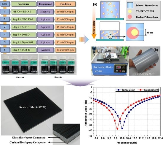
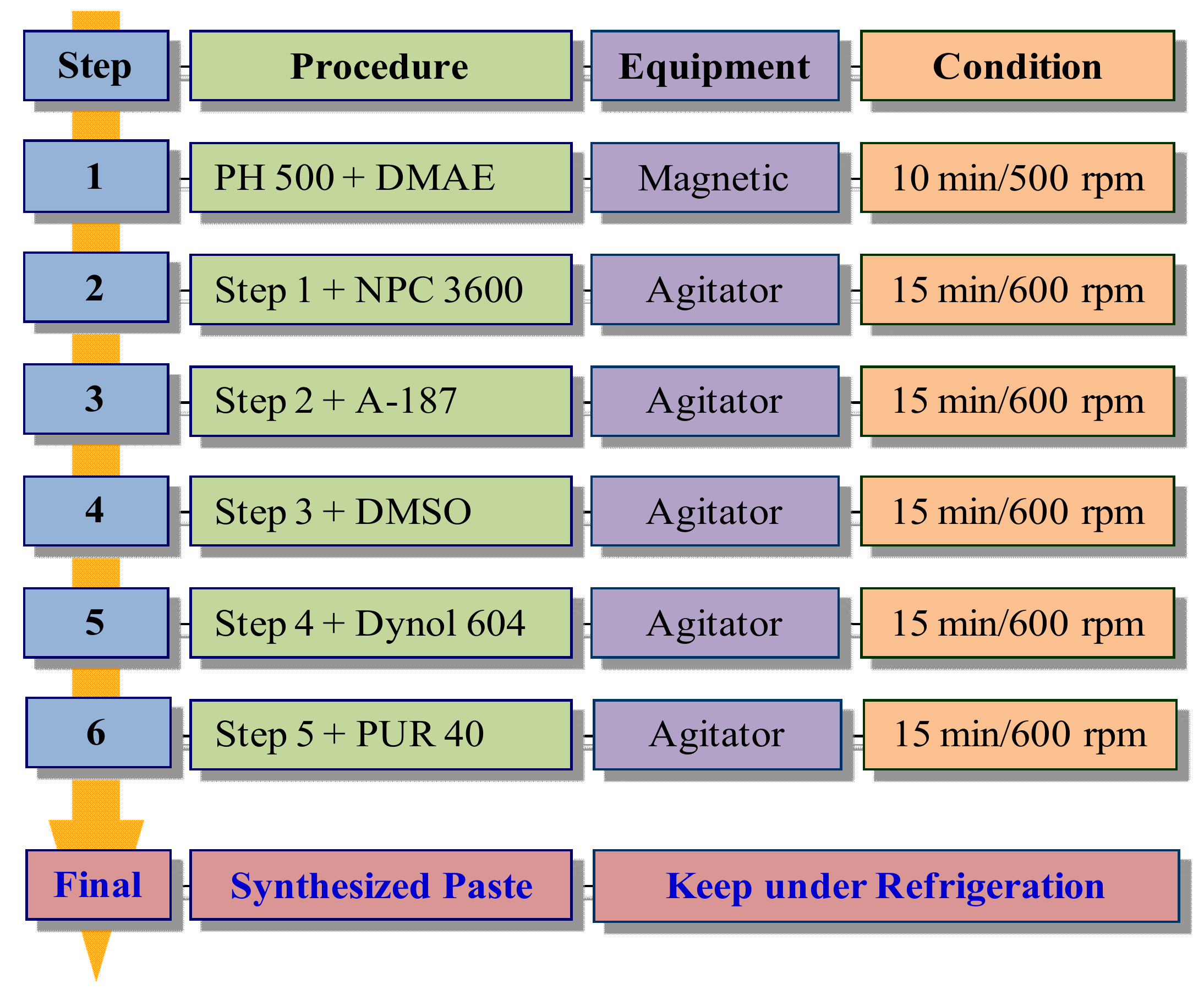
2. Synthesis
2.1. Materials for Conductive Paste
2.2. Conductive Polymer Blend Based on PEDOT:PSS–Polyurethane
3. Characterization
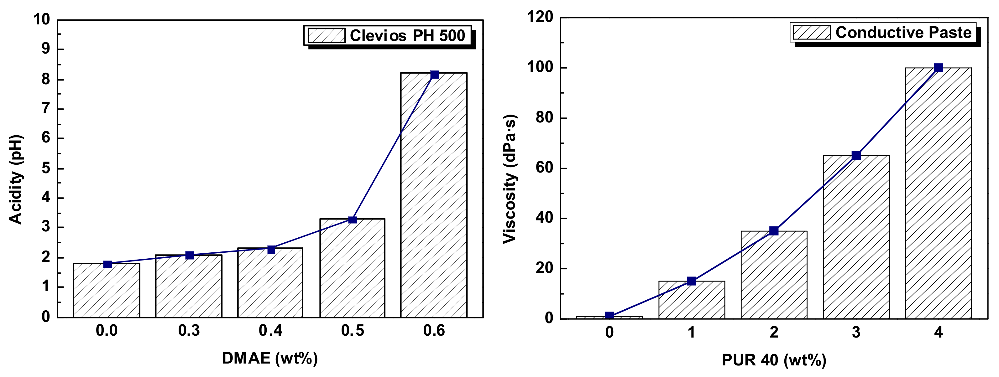
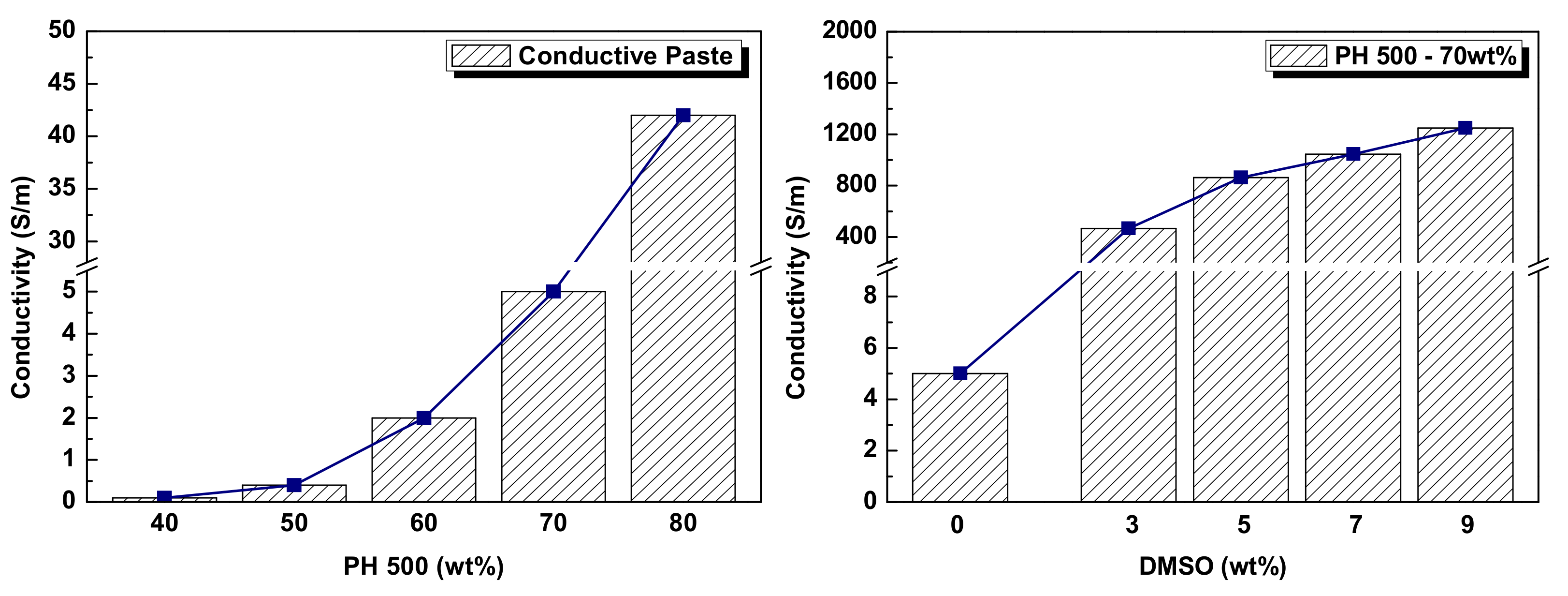
3.1. Electrical Analysis of Conductive Paste
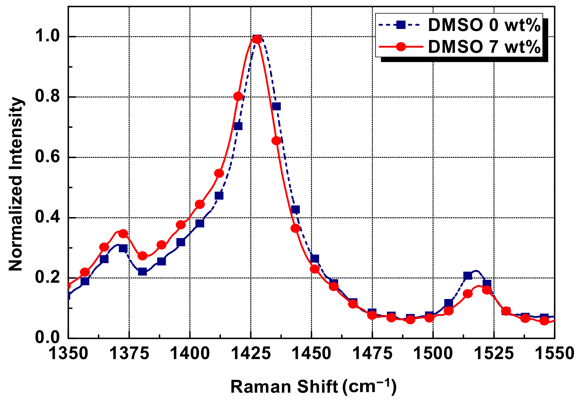
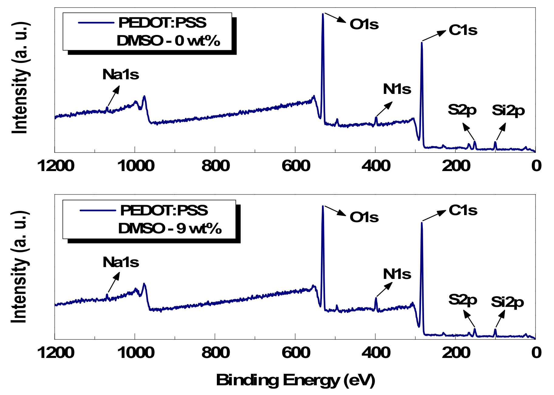
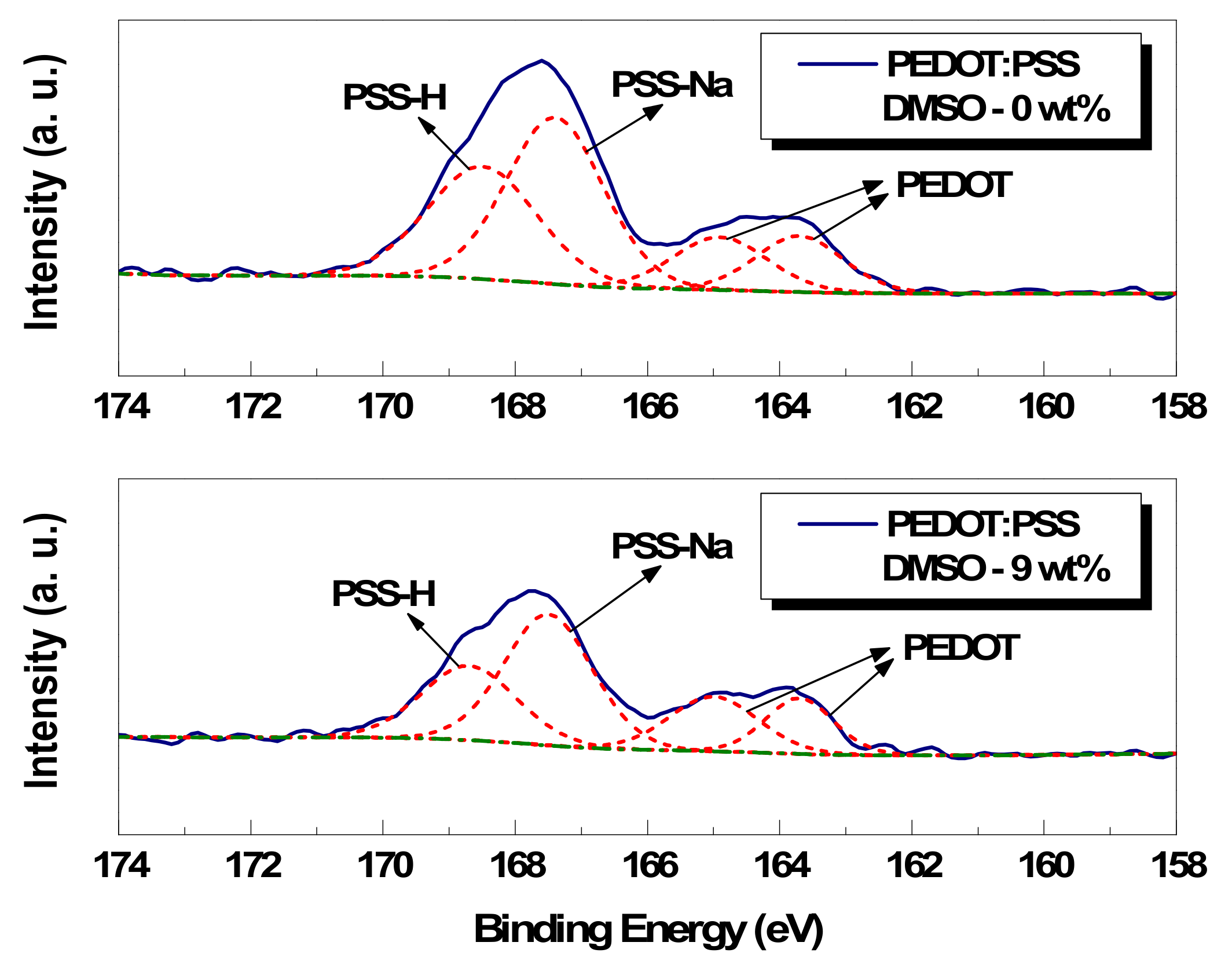
3.2. Chemical Analysis of Conductive Paste
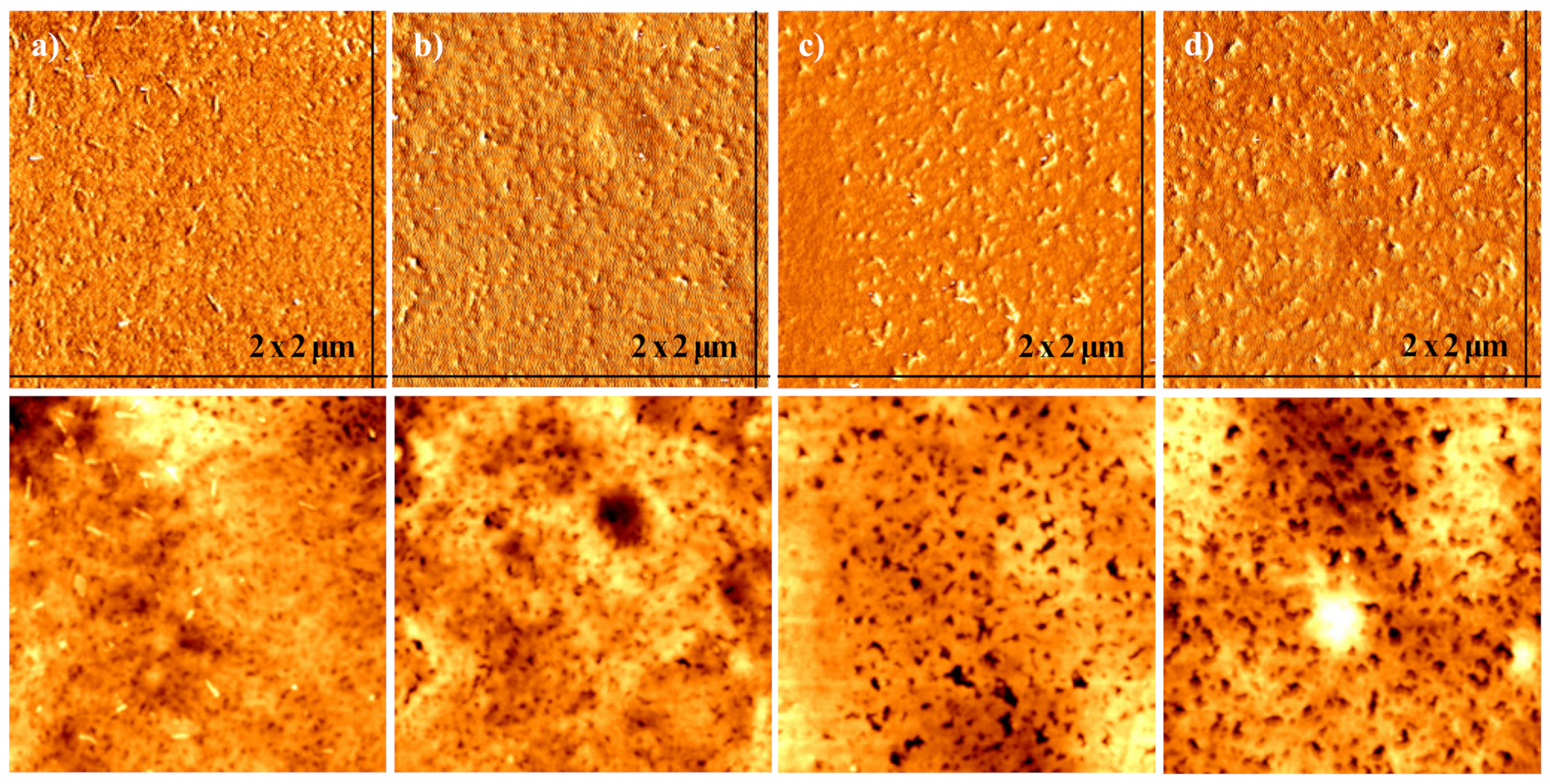
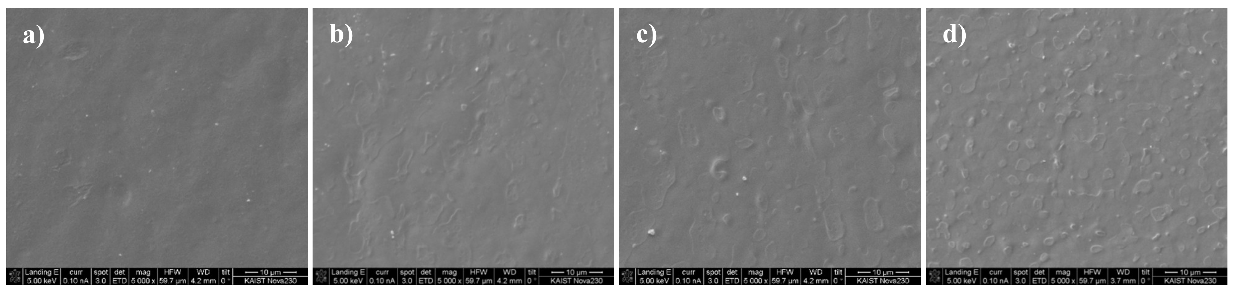
3.3. Morphological Analysis of Conductive Paste
4. Applications
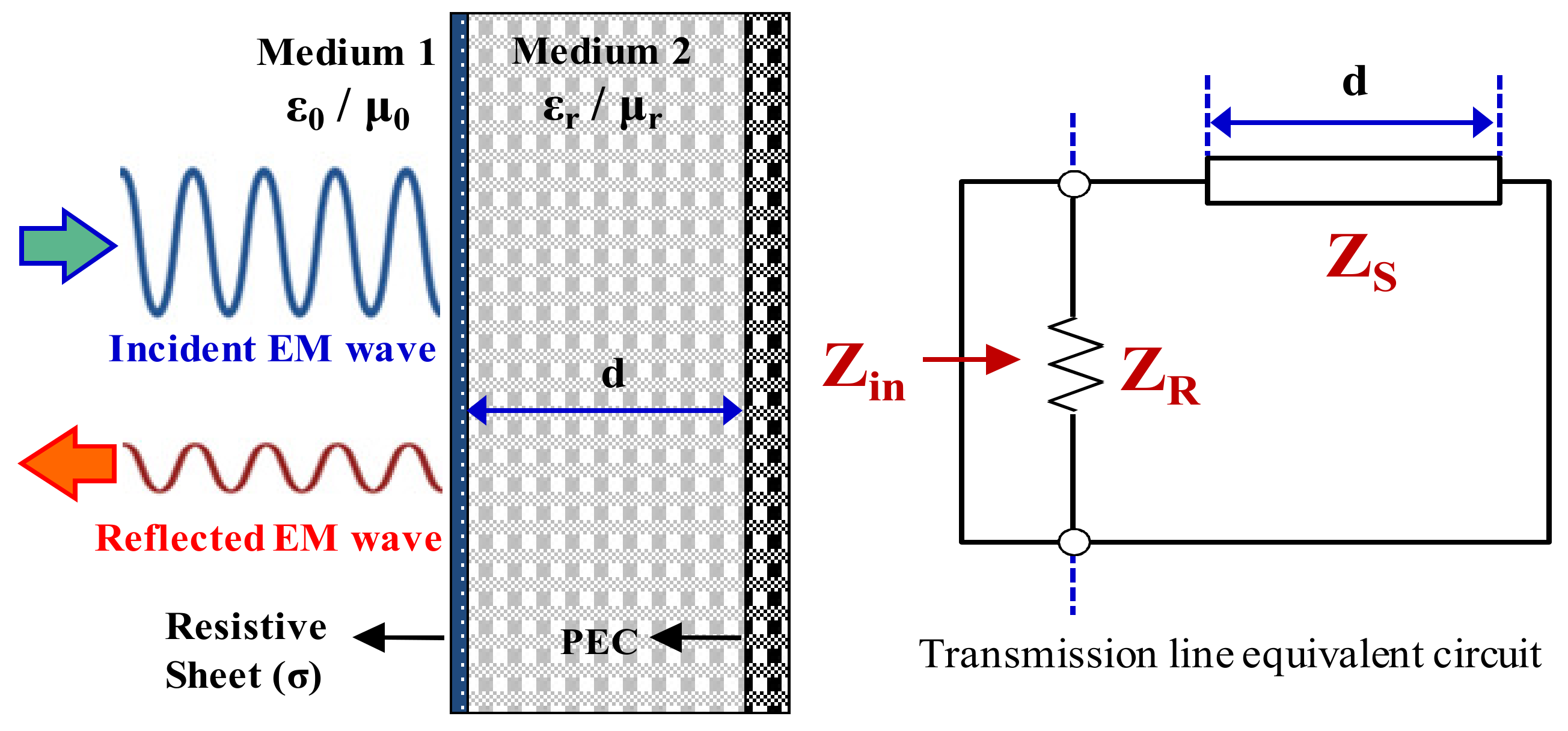
4.1. Design of EM Wave Absorber
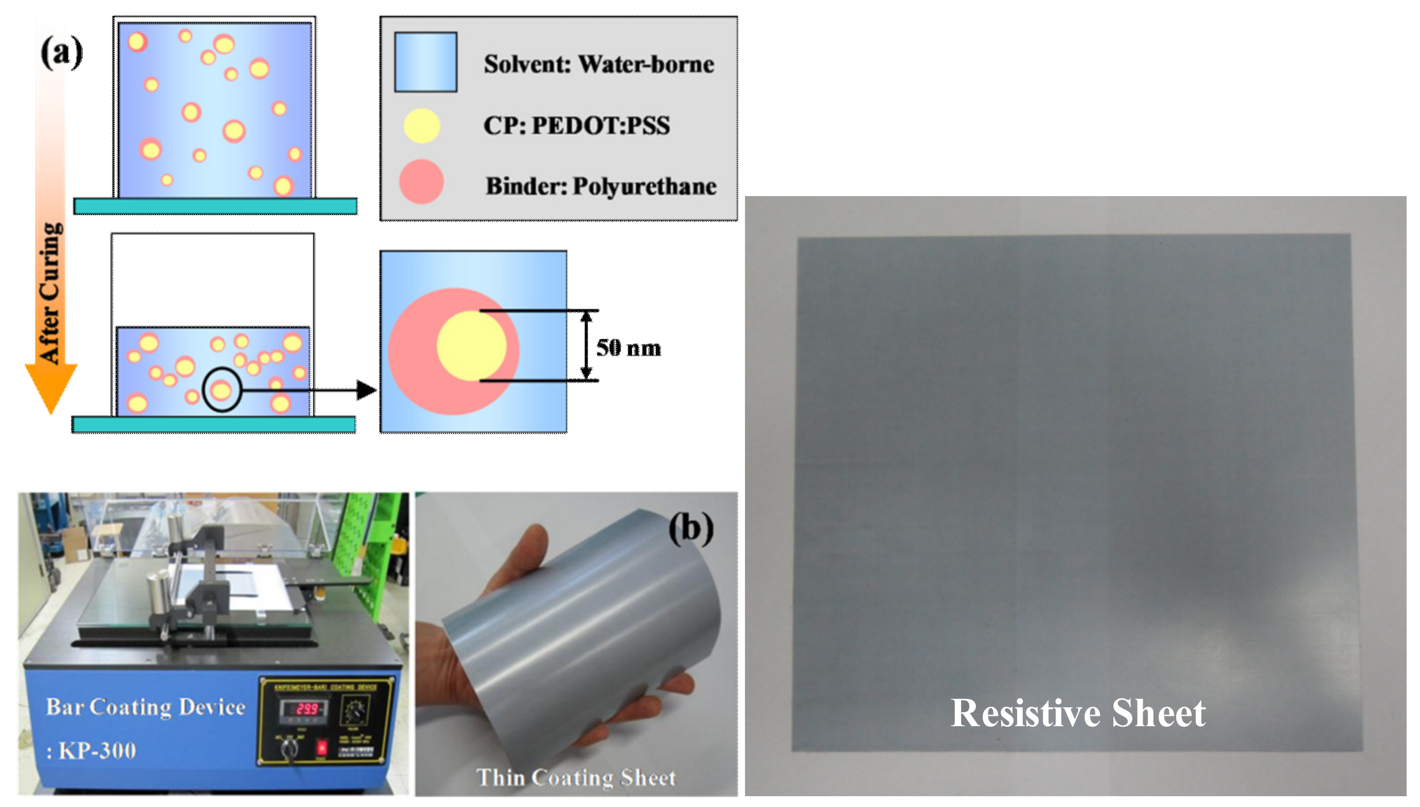
4.2. Fabrication of EM Wave Absorber
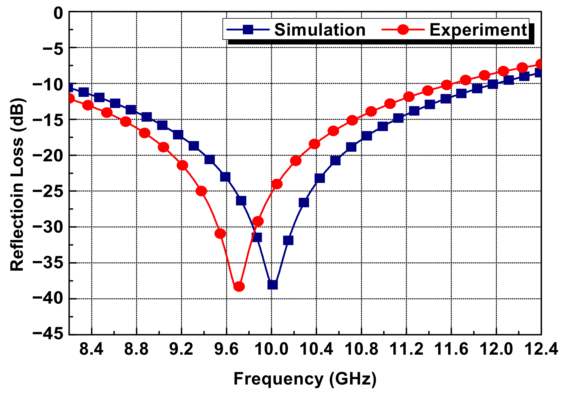
4.3. Electromagnetic Wave-Absorbing Performance
5. Discussion and Conclusions
Author Contributions
Funding
Institutional Review Board Statement
Informed Consent Statement
Data Availability Statement
Conflicts of Interest
References
- Skotheim, T.A.; Reynolds, J.R. Conjugated Polymers, 3rd ed.; CRC Press: Boca Raton, FL, USA, 2006. [Google Scholar]
- Waltman, R.J.; Bargon, J. Electrically conducting polymers: A review of the electropolymerization reaction, of the effects of chemical structure on polymer film properties, and of applications towards technology. Can. J. Chem. 1986, 64, 76–95. [Google Scholar] [CrossRef] [Green Version]
- Harun, M.H.; Saion, E.; Kassim, A.; Yahya, N.; Mahmud, E. Conjugated conducting polymers: A brief overview. J. Adv. Sci. Art. 2007, 2, 63–68. [Google Scholar]
- Groenendaal, L.; Jonas, F.; Freitag, D.; Pielartzik, H.; Reynolds, J.R. Poly(3,4-ethylenedioxythiophene) and its derivatives: Past, present, and future. Adv. Mater. 2000, 12, 481–494. [Google Scholar] [CrossRef]
- Elschner, A.; Kirchmeyer, S.; Lövenich, W.; Merker, U.; Reuter, K. PEDOT: Principles and Applications of an Intrinsically Conducting Polymer; CRC Press: Boca Raton, FL, USA, 2010. [Google Scholar]
- Yang, Y.; Deng, H.; Fu, Q. Recent progress on PEDOT:PSS based polymer blends and composites for flexible electronics and thermoelectric devices. Mater. Chem. Front. 2020, 4, 3130–3152. [Google Scholar] [CrossRef]
- Kirchmeyer, S.; Reuter, K. Scientific importance, properties and growing applications of poly(3,4-ethylenedioxythiophene). J. Mater. Chem. 2005, 15, 2077–2088. [Google Scholar] [CrossRef]
- Shahrim, N.A.A.; Ahmad, Z.; Azman, A.W.; Buys, Y.F.; Sarifuddin, N. Mechanisms for doped PEDOT:PSS electrical conductivitiy improvement. Mater. Adv. 2021, 2, 7118–7138. [Google Scholar] [CrossRef]
- Huang, J.H.; Kekuda, D.; Chu, C.W.; Ho, K.C. Electrochemical characterization of the solvent-enhanced conductivity of poly(3,4-ethylenedioxy-thiophene) and its application in polymer solar cells. J. Mater. Chem. 2009, 19, 3704–3712. [Google Scholar] [CrossRef]
- Jang, H.K.; Shin, J.H.; Kim, C.G.; Shin, S.H.; Kim, J.B. Semi-cylindrical radar absorbing structures using fiber-reinforced composites and conducting polymers in the X-band. Adv. Compos. Mater. 2000, 20, 215–230. [Google Scholar] [CrossRef]
- Truong, V.; Turner, B.D.; Muscat, R.F. Conducting Polymer based Radar Absorbing Materials. In Proceedings of the Smart Materials, Structures and Integrated Systems, Adelaide, Australia, 10–13 December 1997. [Google Scholar]
- Wong, P.T.C.; Chamber, B.; Anderson, A.P.; Wright, P.V. Large area conducting polymer composites and their use in microwave absorbing material. Electron. Lett. 1992, 28, 1651–1653. [Google Scholar] [CrossRef]
- Franchitto, M.; Faez, R.; Orlando, A.J.F. Electromagnetic Behavior of Radar Absorbing Materials based on Conducting Polymers. In Proceedings of the International Microwave and Optoelectronics Conference, Belem, Brazil, 6–10 August 2001. [Google Scholar]
- Wright, P.V.; Chambers, B.; Barnes, A. Progress in smart microwave materials and structures. Smart Mater. Struct. 2000, 9, 273–279. [Google Scholar] [CrossRef]
- Rubeziene, V.; Guzaitiene, J.B.; Abraitiene, A.; Sankauskaite, A.; Ragulis, P.; Santos, G.; Pimenta, J. Development and investigation of PEDOT:PSS composition coated fabrics intended for microwave shielding and absorption. Polymers 2021, 13, 1191. [Google Scholar] [CrossRef] [PubMed]
- Tomasino, D.V.; Wolf, M.; Farina, H.; Chiarello, G.; Feldhoff, A.; Ortenzi, M.A.; Sabatini, V. Role of doping agent degree of surlfonation and casting solvent on the electrical conductivity and morphology of PEDOT:SPAES thin films. Polymers 2021, 13, 658. [Google Scholar] [CrossRef]
- Garnett, E.; Ginley, D. Electrical and morphological properties of inkjet printed PEDOT/PSS films. Energ. J. 2005, 5, 24–29. [Google Scholar]
- Kim, J.Y.; Jung, J.H.; Lee, D.E.; Joo, J. Enhancement of electrical conductivity of poly(3,4-ethylenedioxythiophene)/poly(4-styrenesulfonate) by a change of solvents. Synth. Met. 2002, 126, 311–316. [Google Scholar] [CrossRef]
- Cruz-Cruz, I.; Reyes-Reyes, M.; Aguilar-Frutis, M.A.; Rodriguez, A.G.; López-Sandoval, R. Study of the effect of DMSO concentration on the thickness of the PSS insulating barrier in PEDOT:PSS thin films. Synth. Met. 2010, 160, 1501–1506. [Google Scholar] [CrossRef]
- Na, S.I.; Wang, G.U.; Kim, S.S.; Kim, T.W.; Oh, S.H.; Yu, B.K.; Lee, T.H.; Kim, D.Y. Evolution of nanomorphology and anisotropic conductivity in solvent-modified PEDOT:PSS films for polymeric anodes of polymer solar cells. J. Mater. Chem. 2009, 19, 9045–9053. [Google Scholar] [CrossRef]
- Rwei, S.P.; Lee, Y.H.; Shiu, J.W.; Sasikumar, R.; Shyr, U.T. Chracterization of solvent-treated PEDOT:PSS thin films with enhanced conductivities. Polymers 2019, 11, 134. [Google Scholar] [CrossRef] [Green Version]
- Wang, G.F.; Tao, X.M.; Xin, J.H.; Fei, B. Modification of conducting polymer for polymeric anodes of flexible organic light emitting diodes. Nanoscale Res. Lett. 2009, 4, 613–617. [Google Scholar] [CrossRef] [Green Version]
- Quyang, J.; Xu, Q.; Chu, C.W.; Yang, Y.; Li, G.; Shinar, J. On the mechanism of conductivity enhancement in poly(3,4-ethylendioxythiophene):poly(styrene-sulfonate) film through solvent treatment. Polymer 2004, 45, 8443–8450. [Google Scholar]
- Quyang, J.; Chu, C.W.; Chen, F.C.; Xu, Q.; Yang, Y. High-conductivity poly(3,4-ethylenedioxythiophene)-poly(styrenesulfonate) film and its application in polymer optoelectronic devices. Adv. Funct. Mater. 2005, 15, 203–208. [Google Scholar]
- Crispin, X.; Marciniak, S.; Osikowicz, W.; Zotti, G.; Gon, A.W.D.; Louwet, F.; Fahlman, M.; Groenendaal, L.; Schryver, F.D.; Salaneck, W.R. Conductivity, morphology, interfacial chemistry, and stability of poly(3,4-ethylenedioxythiophene)-poly(styrene sulfonate): A photoelectron spectroscopy study. J. Polym. Sci. Pol. Phys. 2003, 41, 2561–2583. [Google Scholar] [CrossRef]
- Greczynski, G.; Kugler, T.; Keil, M.; Osikowicz, W.; Fahlman, M.; Salaneck, W.R. Photoelectron spectroscopy of thin films of PEDOT-PSS conjugated polymer blend: A mini-review and some new results. J. Electron. Spectrosc. 2001, 121, 1–17. [Google Scholar] [CrossRef]
- Reyes-Reyes, M.; Cruz-Cruz, I.; López-Sandoval, R. Enhancement of the electrical conductivity in PEDOT:PSS films by the addition of dimethyl sulfate. J. Phys. Chem. 2010, 114, 20220–20224. [Google Scholar] [CrossRef]
- Nardes, A.M.; Janssen, R.A.J.; Kemerink, M.A. Morphological Model for the Solvent-Enhanced Conductivity of PEDOT:PSS Thin Films. Adv. Funct. Mater. 2008, 18, 865–871. [Google Scholar] [CrossRef]
- Vinoy, K.J.; Jha, R.M. Radar Absorbing Materials: From Theory to Design and Characterization; Kluwer Academic Publishers: Norwell, MA, USA, 1996. [Google Scholar]


| Category | Product Name | Characteristics |
|---|---|---|
| Conductive Material | Clevios PH 500 |
|
| Binding Material | NPC-3600 |
|
| Secondary Compound | DMAE (Dimethylaminoethanol) | - pH control agent |
| Silquest A-187 | - Coupling agent | |
| Dynol 604 | - Surface active agent | |
| DMSO (Dimethylsulfoxide) | - Conductive enhancer | |
| Tafigel PUR 40 | - Thickening agent |
| Polymer | 0 wt% DMSO | 3 wt% DMSO | 5 wt% DMSO | 9 wt% DMSO | ||||
|---|---|---|---|---|---|---|---|---|
| Binding Energy | Area Ratio | Binding Energy | Area Ratio | Binding Energy | Area Ratio | Binding Energy | Area Ratio | |
| PEDOT/PSS | 284.3 eV | 47.7% | 284.3 eV | 52.0% | 284.5 eV | 52.3% | 284.4 eV | 51.4% |
| PSS | 285.9 eV | 47.0% | 285.9 eV | 42.0% | 286.1 eV | 41.4% | 286.0 eV | 41.5% |
| PEDOT | 288.6 eV | 5.3% | 288.6 eV | 6.0% | 288.7 eV | 6.3% | 288.6 eV | 7.1% |
| Polymer | 0 wt% DMSO | 3 wt% DMSO | 5 wt% DMSO | 9 wt% DMSO | ||||
|---|---|---|---|---|---|---|---|---|
| Binding Energy | Area Ratio | Binding Energy | Area Ratio | Binding Energy | Area Ratio | Binding Energy | Area Ratio | |
| PEDOT | 163.7 eV | 12.8% | 163.8 eV | 14.8% | 163.8 eV | 15.2% | 163.9 eV | 13.9% |
| PEDOT | 164.9 eV | 13.0% | 165.0 eV | 11.6% | 165.0 eV | 14.1% | 165.0 eV | 17.8% |
| PSS-Na | 167.4 eV | 42.0% | 167.3 eV | 42.6% | 167.6 eV | 37.7% | 167.5 eV | 42.4% |
| PSS-H | 168.5 eV | 32.2% | 168.5 eV | 31.0% | 168.5 eV | 33.0% | 168.7 eV | 25.9% |
| Parameter | Value | Parameter | Value |
|---|---|---|---|
| Conductivity (CR) | 1000 S/m | Permittivity (ε′/ε″) | 4.57/0.05 |
| Substrate Size (LS) | 161 mm | Substrate Thickness (HS) | 3.5 mm |
| Sheet Thickness (HR) | 2.65 µm | Ground Thickness (HG) | 0.2 mm |
Publisher’s Note: MDPI stays neutral with regard to jurisdictional claims in published maps and institutional affiliations. |
© 2022 by the authors. Licensee MDPI, Basel, Switzerland. This article is an open access article distributed under the terms and conditions of the Creative Commons Attribution (CC BY) license (https://creativecommons.org/licenses/by/4.0/).
Share and Cite
Jang, H.-K.; Kim, J.; Park, J.-S.; Moon, J.B.; Oh, J.; Lee, W.-K.; Kang, M.-G. Synthesis and Characterization of a Conductive Polymer Blend Based on PEDOT:PSS and Its Electromagnetic Applications. Polymers 2022, 14, 393. https://doi.org/10.3390/polym14030393
Jang H-K, Kim J, Park J-S, Moon JB, Oh J, Lee W-K, Kang M-G. Synthesis and Characterization of a Conductive Polymer Blend Based on PEDOT:PSS and Its Electromagnetic Applications. Polymers. 2022; 14(3):393. https://doi.org/10.3390/polym14030393
Chicago/Turabian StyleJang, Hong-Kyu, Jinbong Kim, Ji-Sang Park, Jin Bum Moon, Jaecheol Oh, Woo-Kyoung Lee, and Min-Gyu Kang. 2022. "Synthesis and Characterization of a Conductive Polymer Blend Based on PEDOT:PSS and Its Electromagnetic Applications" Polymers 14, no. 3: 393. https://doi.org/10.3390/polym14030393
APA StyleJang, H.-K., Kim, J., Park, J.-S., Moon, J. B., Oh, J., Lee, W.-K., & Kang, M.-G. (2022). Synthesis and Characterization of a Conductive Polymer Blend Based on PEDOT:PSS and Its Electromagnetic Applications. Polymers, 14(3), 393. https://doi.org/10.3390/polym14030393