Failure-Mode Shift of Metal/Composite L-Joint with Grooved Structure under Compressive Load
Abstract
:1. Introduction
2. Specimen Manufacturing and Testing
3. Simulation Study
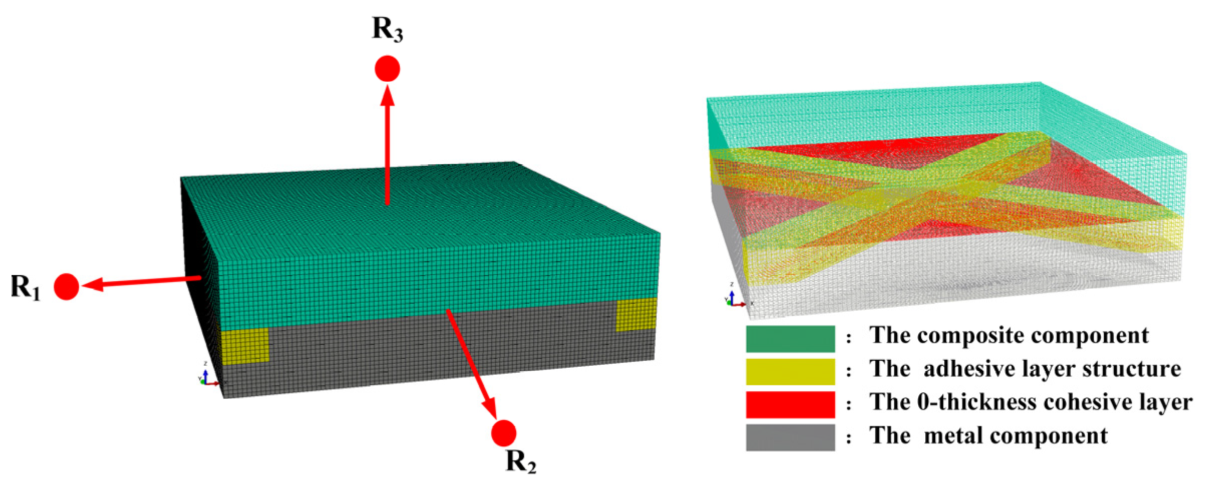
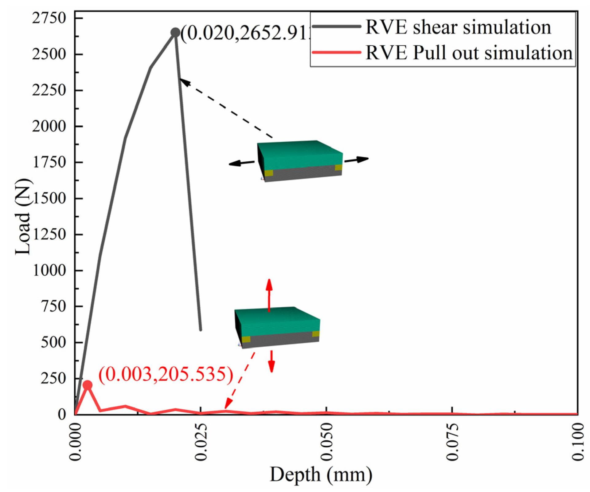
3.1. Establishment of RVE Model
3.2. Material Parameters of the Equivalent Cohesive Layer
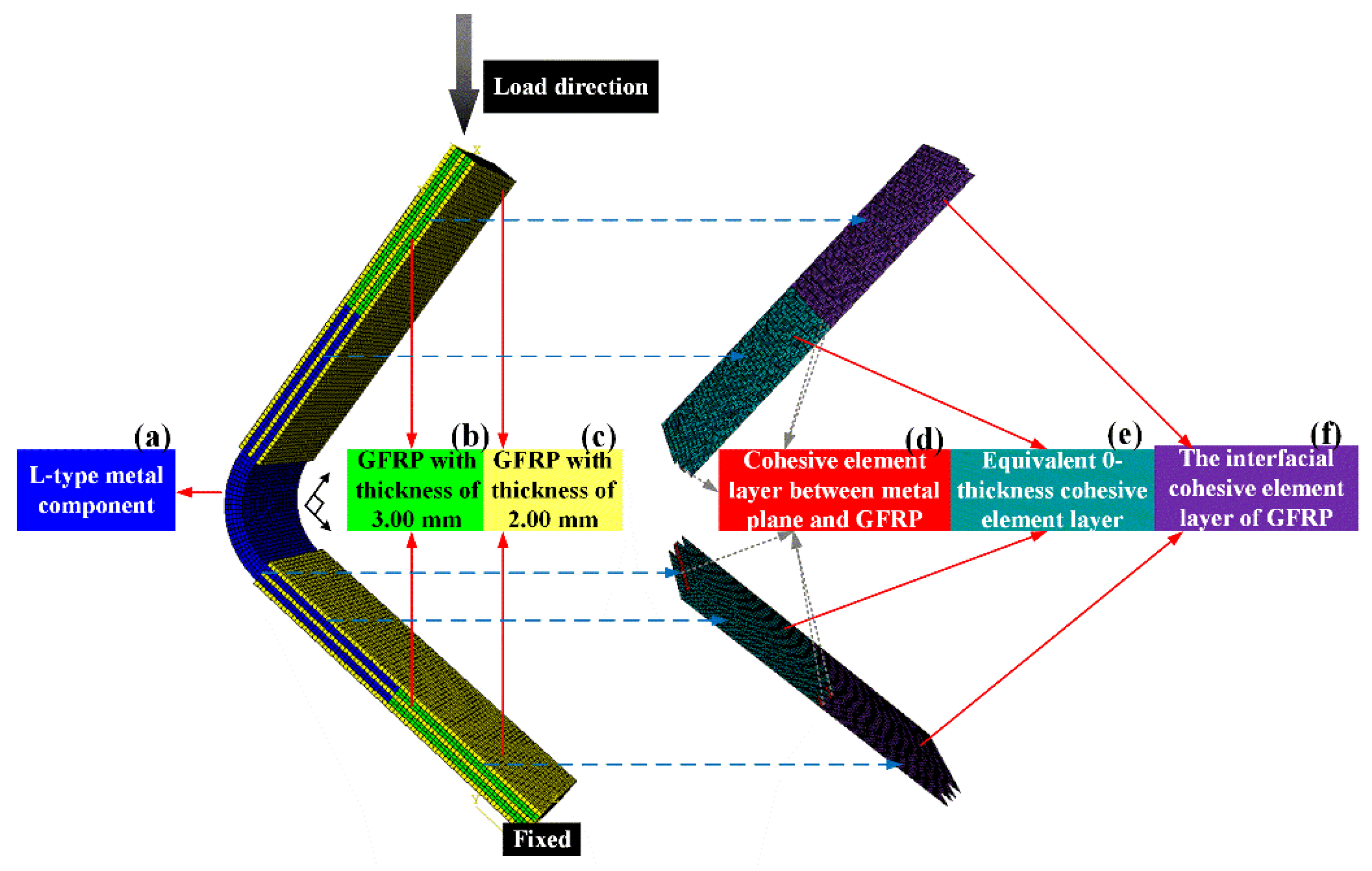
3.3. Simulation of Equivalent Metal/GFRP Joints
4. Results and Discussion
4.1. Analysis of Experimental and Simulation Results of L-Joints with Different Bonding Lengths
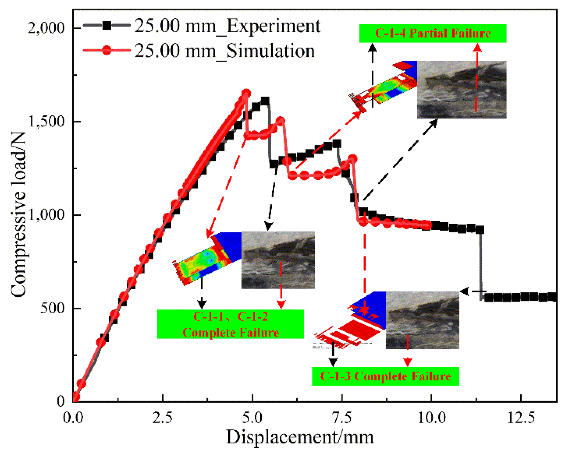
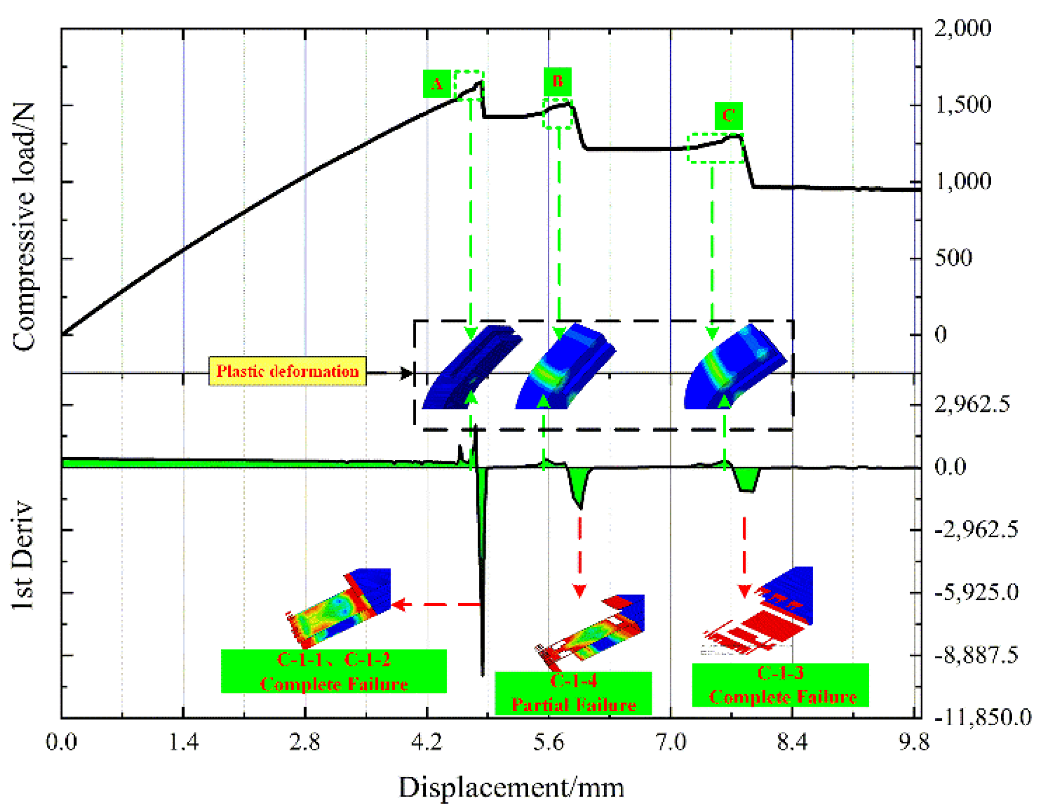
4.1.1. L-Joint with Bonding Length of 25.00 mm
4.1.2. L-Joint with Bonding Length of 40.00 mm, 55.00 mm and 70.00 mm
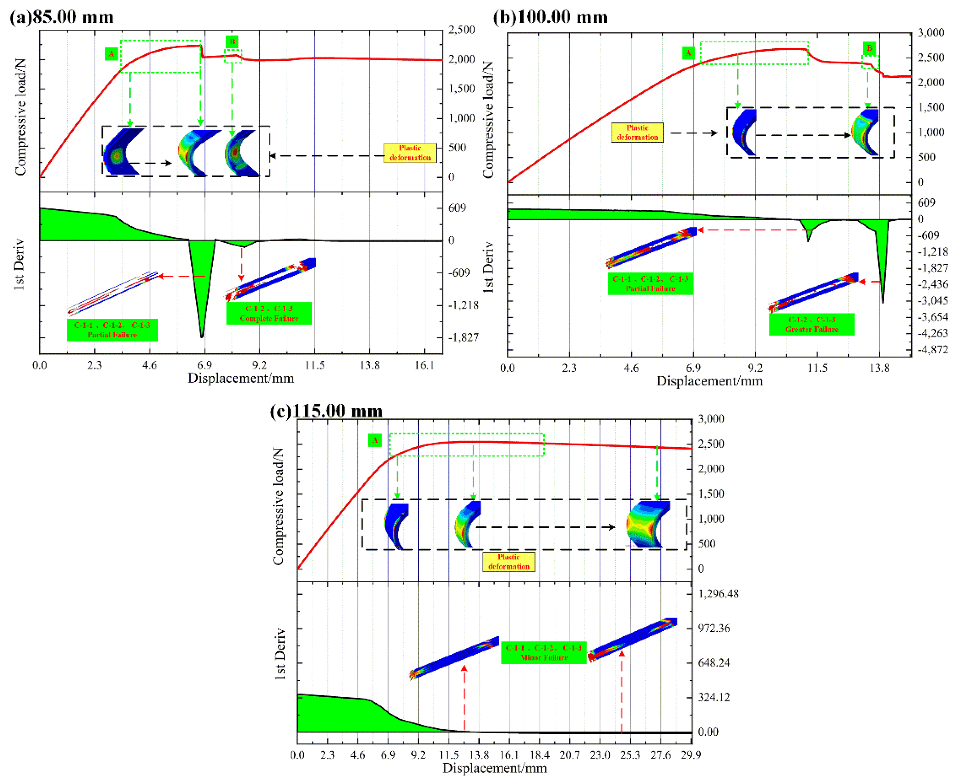
4.1.3. L-Joint with Bonding Length of 85.00 mm, 100.00 mm and 115.00 mm
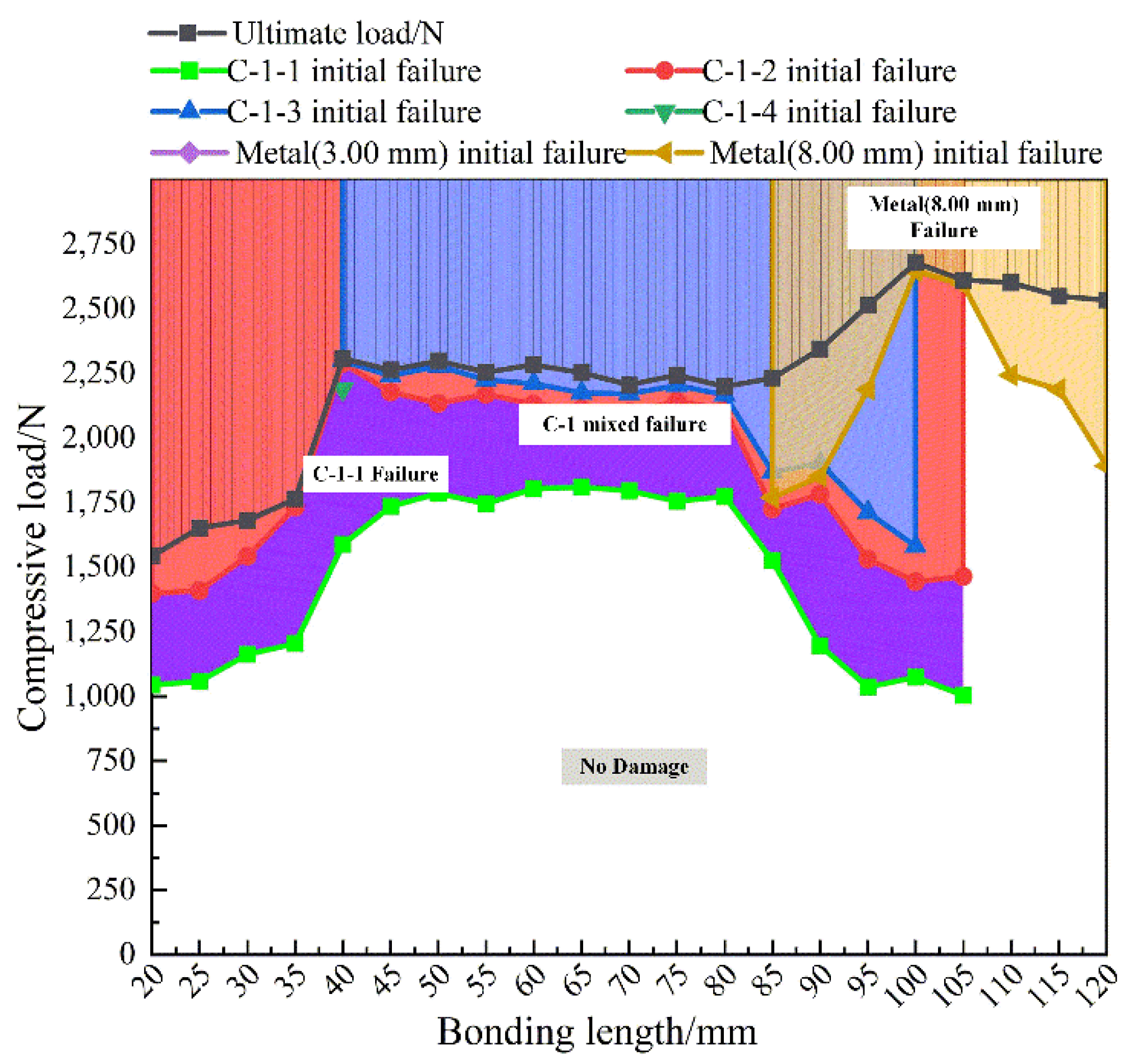
4.2. Relationship between Failure Mode and Compressive Load for L-Joints
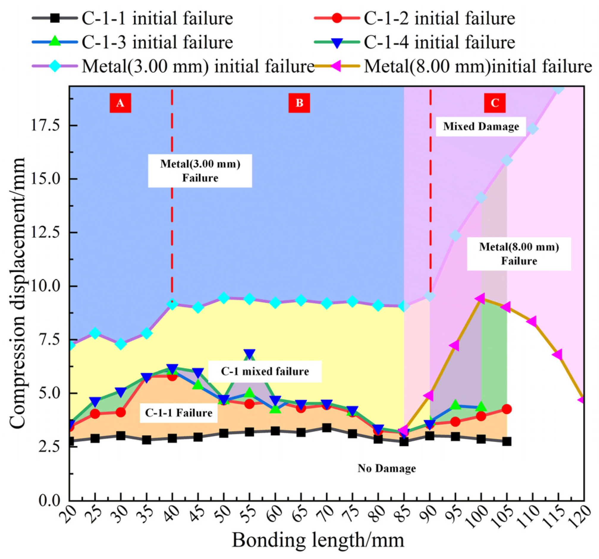
4.3. Relationship between Failure Mode and Compressive Displacement for L-Joints
5. Conclusions
- (1)
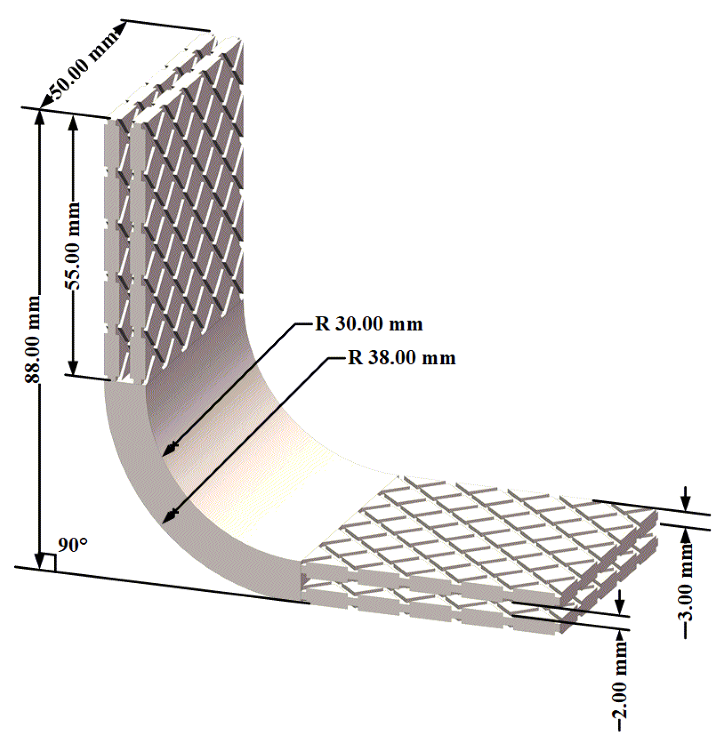
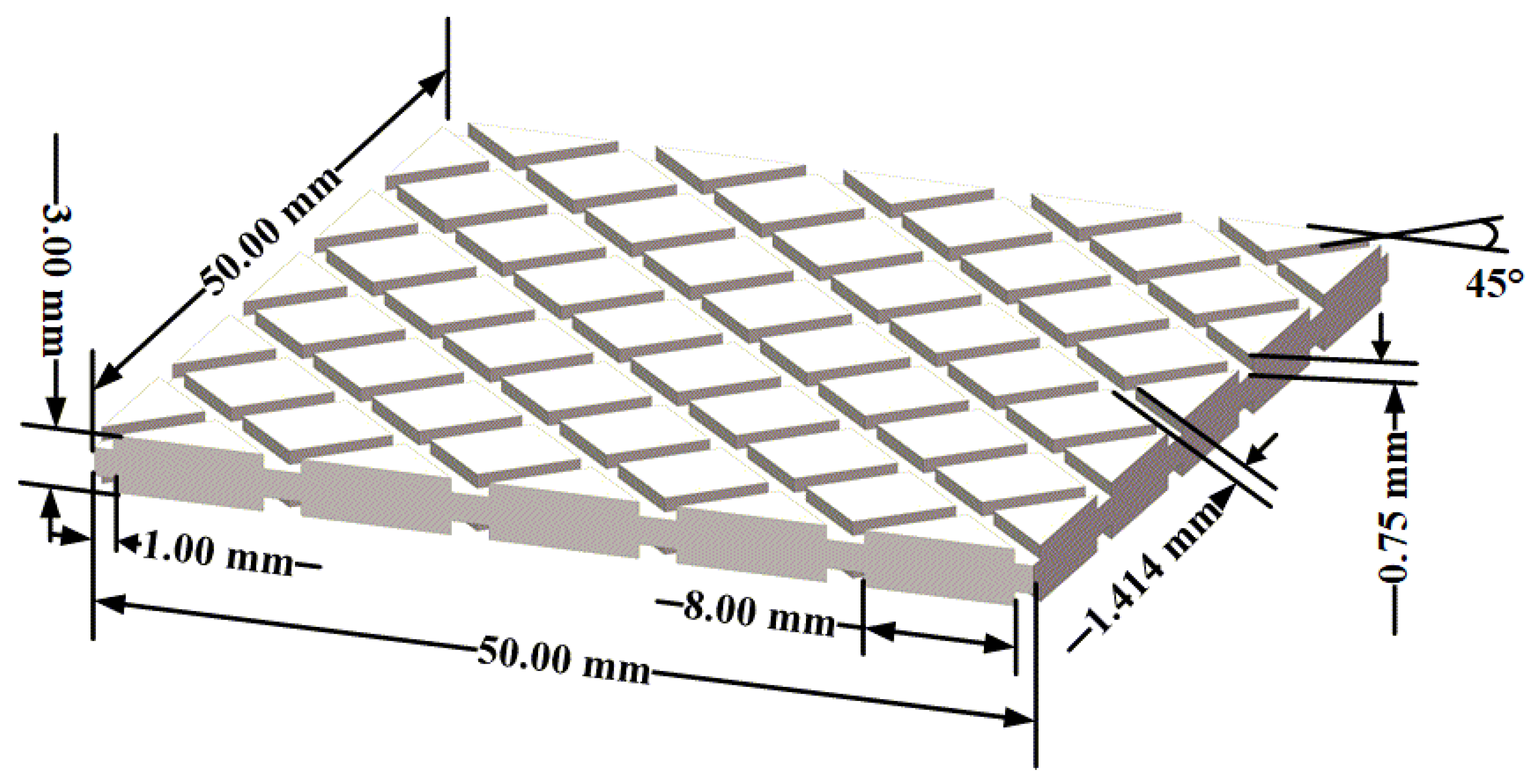
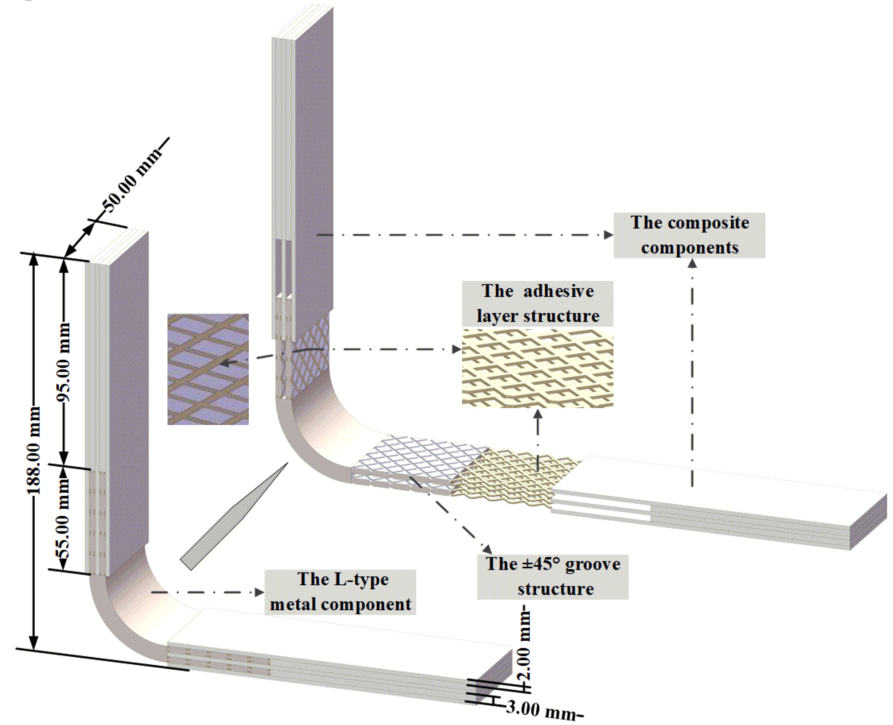
- In the simulation analysis of metal/composite L-joints, the groove structure is equivalent to a 0-thickness element layer. The applicability of the simulation method is verified by comparing the ultimate load, displacement and failure mode of the test and simulation.
- (2)
- The failure modes of L-joints with different bond lengths are analyzed, and the following conclusions are drawn: When the bonding length is 25.00 mm and 40.00 mm, C-1-1 firstly fails completely, then C-1-2 and C-1-3 fail completely, and most of thestructures of metal components and composite components are de-bonded; when the bonding length is 55.00 mm, 70.00 mm and 85.00 mm, C-1-1 fails first but not completely, while C-1-2 and C-1-3 fail completely, and Metal (3.00 mm) continues to carry the compressive load; when the bonding length is 100.00 mm and 115.00 mm, C-1 does not fail completely. At this time, the metal component bears a large bending load, and the overall structure of the metal/composite L-joint is greatly bent.
- (3)
- When the bond length is 25.00–40.00 mm, after the metal/composite L-joint fails, the metal and composite components warp due to excessive compressive displacement. When the bonding length is greater than 100.00 mm, there is no obvious separation of the metal and composite components, and the metal/composite L-joint has obvious overall bending.
- (4)
- Finally, the simulation method is used to simulate the compression of more metal/composite L-joints with different bond lengths, and the prediction graphs of failure displacement and failure mode are produced. According to the failure prediction diagram, designers can select the corresponding bonding length according to their own needs; this provides a reference for the design of metal/composite hybrid L-joints.
Author Contributions
Funding
Institutional Review Board Statement
Informed Consent Statement
Data Availability Statement
Conflicts of Interest
References
- Khosravani, M.; Weinberg, K. Experimental investigations of the environmental effects on stability and integrity of composite sandwich t-joints: Experimentelle untersuchung des umwelteinflusses auf die belastbarkeit von t-stößen in sandwich-platten. Mater. Und Werkst. 2017, 48, 753–759. [Google Scholar] [CrossRef]
- Santiuste, C.; Sánchez-Sáez, S.; Barbero, E. A comparison of progressive-failure criteria in the prediction of the dynamic bending failure of composite laminated beams. Compos. Struct. 2010, 92, 2406–2414. [Google Scholar] [CrossRef] [Green Version]
- Savin-Barcan, M.; Beznea, E.; Chirica, I. Influence of Fabrication Imperfections on Dynamic Response of a Sandwich Composite Panel of a Ship Deck Structure; Presented at IOP Conference Series: Materials Science and Engineering; IOP Publishing: Constanta, Romania, 2018; Volume 400, p. 032008. [Google Scholar]
- Mouritz, P.A.; Gellert, E.; Burchill, P.; Challis, K. Review of advanced composite structures for naval ships and submarines. Compos. Struct. 2001, 53, 21–42. [Google Scholar] [CrossRef]
- Li, H.; Tu, S.; Liu, Y.; Lu, X.; Zhu, X. Mechanical properties of l-joint with composite sandwich structure. Compos. Struct. 2019, 217, 165–174. [Google Scholar] [CrossRef]
- Khosravani, R.M.; Nasiri, S.; Weinberg, K. Prediction of fracture in sandwich-structured composite joints using case-based reasoning approach. Procedia Struct. Integr. 2018, 13, 168–173. [Google Scholar] [CrossRef]
- Shen, W.; Yan, R.; Luo, B.; Zhu, Y.; Zeng, H. Ultimate strength analysis of composite typical joints for ship structures. Compos. Struct. 2017, 171, 32–42. [Google Scholar] [CrossRef]
- Kim, J.; Park, B.; Han, Y. Evaluation of fatigue characteristics for adhesively-bonded composite stepped lap joint. Compos. Struct. 2004, 66, 69–75. [Google Scholar] [CrossRef]
- Feih, S.; Shercliff, H. Adhesive and composite failure prediction of single-l joint structures under tensile loading. Int. J. Adhes. Adhes. 2005, 25, 47–59. [Google Scholar] [CrossRef]
- Feih, S.; Shercliff, H. Composite failure prediction of single-l joint structures under bending. Compos. Part A Appl. Sci. Manuf. 2005, 36, 381–395. [Google Scholar] [CrossRef]
- Kai, Q.; Renjun, Y.; Mingen, C.; Haiyan, Z. Failure mode shift of sandwich composite l-joint for ship structures under tension load. Ocean. Eng. 2020, 214, 107863. [Google Scholar] [CrossRef]
- Zeng, H.; Yan, R.; Xu, L. Failure prediction of composite sandwich l-joint under bending. Compos. Struct. 2018, 197, 54–62. [Google Scholar] [CrossRef]
- Kinvi-Dossou, G.; Boumbimba, R.M.; Bonfoh, N.; Garzon-Hernandez, S.; Garcia-Gonzalez, D.; Gerard, P.; Arias, A. Innovative acrylic thermoplastic composites versus conventional composites: Improving the impact performances. Compos. Struct. 2019, 217, 1–13. [Google Scholar] [CrossRef]
- Zhang, J.; Xie, Q.; Xie, Y.; Zhou, L.; Wang, Z. Investigation of mechanical performances of composite bolted joints with local reinforcements. Sci. Eng. Compos. Mater. 2018, 25, 75–83. [Google Scholar] [CrossRef]
- Liu, J.Y.; Chen, X. Evaluations of the effective material properties of carbon nanotube-based composites using a nanoscale representative volume element. Mech. Mater. 2003, 35, 69–81. [Google Scholar] [CrossRef]
- Mohammadpour, E.; Awang, M.; Kakooei, S.; Akil, H.M. Modeling the tensile stress–strain response of carbon nanotube/polypropylene nanocomposites using nonlinear representative volume element. Mater. Des. 2014, 58, 36–42. [Google Scholar] [CrossRef]
- Hashin, Z. Fatigue failure criteria for unidirectional fiber composites. J. Appl. Mech. Dec. 1981, 48, 846–852. [Google Scholar] [CrossRef]
- Boufaida, Z.; Boisse, J.; André, S.; Farge, L. Mesoscopic strain field analysis in a woven composite using a spectral solver and 3d-dic measurements. Compos. Struct. 2017, 160, 604–612. [Google Scholar] [CrossRef]
- Tan, S.C. A progressive failure model for composite laminates containing openings. J. Compos. Mater. 1991, 25, 556–577. [Google Scholar] [CrossRef]
- Kang, Z.; Shi, Z.; Lei, Y.; Xie, Q.; Zhang, J. Effect of the surface morphology on the bonding performance of metal/composite hybrid structures. Int. J. Adhes. Adhes. 2021, 111, 102944. [Google Scholar] [CrossRef]
- Truong, -H.V.; Kwak, B.-S.; Roy, R.; Kweon, J.-H. Cohesive zone method for failure analysis of scarf patch-repaired composite laminates under bending load. Compos. Struct. 2019, 222, 110895. [Google Scholar] [CrossRef]
- Truong, -H.V.; Nguyen, K.-H.; Park, S.-S.; Kweon, J.-H. Failure load analysis of c-shaped composite beams using a cohesive zone model. Compos. Struct. 2018, 184, 581–590. [Google Scholar] [CrossRef]
- Nguyen, -H.K.; Ju, H.-W.; Truong, V.-H.; Kweon, J.-H. Delamination analysis of multi-angle composite curved beams using an out-of-autoclave material. Compos. Struct. 2018, 183, 320–330. [Google Scholar] [CrossRef]





| Initial Stiffness (MPa/mm) | Interlaminar Strength (MPa) | Fracture Toughness (J/mm2) | ||||||
|---|---|---|---|---|---|---|---|---|
| Kn | Kt | Ks | N | T | S | GIC | GIIC | GIIIC |
| 5811 | 5811 | 5811 | 2.05 | 26.53 | 26.53 | 0.085 | 2.65 | 2.65 |
| Failure Mode | Failure Criterion | Material Degradation Criterion |
|---|---|---|
| Fiber tensile failure | ||
| Fiber compression failure | ||
| Matrix tensile failure | ||
| Matrix compression failure | ||
| Tensile delamination failure | ||
| Compression delamination failure |
| Bonding Length | Ultimate Load/N | Displacement Corresponding to Ultimate Load/mm | ||||
|---|---|---|---|---|---|---|
| Experiment | Simulation | Deviation Ratio/% | Experiment | Simulation | Deviation Ratio/% | |
| 40.00 mm | 2166.25 | 2308.64 | 6.57 | 6.95 | 6.34 | 8.78 |
| 55.00 mm | 2075.22 | 2255.98 | 8.71 | 6.41 | 5.38 | 16.06 |
| 70.00 mm | 2071.91 | 2206.83 | 6.51 | 6.42 | 6.10 | 4.95 |
| Bonding Length | Ultimate Load/N | Displacement Corresponding to Ultimate Load/mm | ||||
|---|---|---|---|---|---|---|
| Experiment | Simulation | Deviation Ratio/% | Experiment | Simulation | Deviation Ratio/% | |
| 85.00 mm | 2050.47 | 2232.69 | 9.89 | 7.35 | 6.76 | 8.03 |
| 100.00 mm | 2615.07 | 2677.64 | 2.39 | 11.56 | 10.83 | 6.31 |
| 115.00 mm | 2422.13 | 2547.18 | 5.16 | 16.57 | 14.82 | 10.56 |
| Failure Structure | C-1-1 | C-1-2 | C-1-3 | C-1-4 | Metal (8.00 mm) | Ultimate Load |
|---|---|---|---|---|---|---|
| Bonding length 25.00 mm | 1058.38 N | 1409.94 N | 1652.02 N | |||
| Bonding length 40.00 mm | 1588.23 N | 2290.35 N | 2300.11 N | 2190.23 N | 2308.61 N | |
| Bonding length 55.00 mm | 1746.51 N | 2169.06 N | 2224.84 N | 2255.95 N | ||
| Bonding length 70.00 mm | 1796.48 N | 2101.12 N | 2172.15 N | 2206.80 N | ||
| Bonding length 85.00 mm | 1525.68 N | 1725.89 N | 1868.06 N | 1770.53 N | 2232.63 N | |
| Bonding length 100.00 mm | 1075.14 N | 1444.15 N | 1581.67 N | 2647.89 N | 2679.46 N | |
| Bonding length 115.00 mm | 2188.98 N | 2548.96 N |
| Failure Structure | C-1-1 | C-1-2 | C-1-3 | C-1-4 | Metal (3.00 mm) | Metal (8.00 mm) |
|---|---|---|---|---|---|---|
| Bonding length 25.00 mm | 2.89 mm | 4.04 mm | 8.03 mm | 6.12 mm | 8.03 mm | |
| 4.48 mm | 4.48 mm | |||||
| Bonding length 40.00 mm | 6.40 mm | 6.40 mm | 6.40 mm | 6.40 mm | 9.16 mm | |
| 8.61 mm | 8.61 mm | 9.16 mm | ||||
| Bonding length 55.00 mm | 5.79 mm | 5.79 mm | 5.79 mm | 7.00 mm | ||
| 7.00 mm | 7.00 mm | |||||
| Bonding length 70.00 mm | 6.32 mm | 6.32 mm | 6.32 mm | 6.32 mm | ||
| 10.21 mm | ||||||
| Bonding length 85.00 mm | 7.35 mm | 7.35 mm | 7.35 mm | 9.07 mm | ||
| 9.07 mm | 9.07 mm | |||||
| Bonding length 100.00 mm | 12.00 mm | 12.00 mm | 12.00 mm | 14.14 mm | ||
| Bonding length 115.00 mm | 12.45 mm |
Publisher’s Note: MDPI stays neutral with regard to jurisdictional claims in published maps and institutional affiliations. |
© 2022 by the authors. Licensee MDPI, Basel, Switzerland. This article is an open access article distributed under the terms and conditions of the Creative Commons Attribution (CC BY) license (https://creativecommons.org/licenses/by/4.0/).
Share and Cite
Kang, Z.; Liu, Z.; Lei, Y.; Zhang, J. Failure-Mode Shift of Metal/Composite L-Joint with Grooved Structure under Compressive Load. Polymers 2022, 14, 1051. https://doi.org/10.3390/polym14051051
Kang Z, Liu Z, Lei Y, Zhang J. Failure-Mode Shift of Metal/Composite L-Joint with Grooved Structure under Compressive Load. Polymers. 2022; 14(5):1051. https://doi.org/10.3390/polym14051051
Chicago/Turabian StyleKang, Zhenhang, Zhu Liu, Yongpeng Lei, and Jifeng Zhang. 2022. "Failure-Mode Shift of Metal/Composite L-Joint with Grooved Structure under Compressive Load" Polymers 14, no. 5: 1051. https://doi.org/10.3390/polym14051051
APA StyleKang, Z., Liu, Z., Lei, Y., & Zhang, J. (2022). Failure-Mode Shift of Metal/Composite L-Joint with Grooved Structure under Compressive Load. Polymers, 14(5), 1051. https://doi.org/10.3390/polym14051051


