

Service Life Prediction of Type-IV Composite CNG Cylinder under the Influence of Drivers’ Refueling Habits—A Numerical Study


Abstract
:1. Introduction
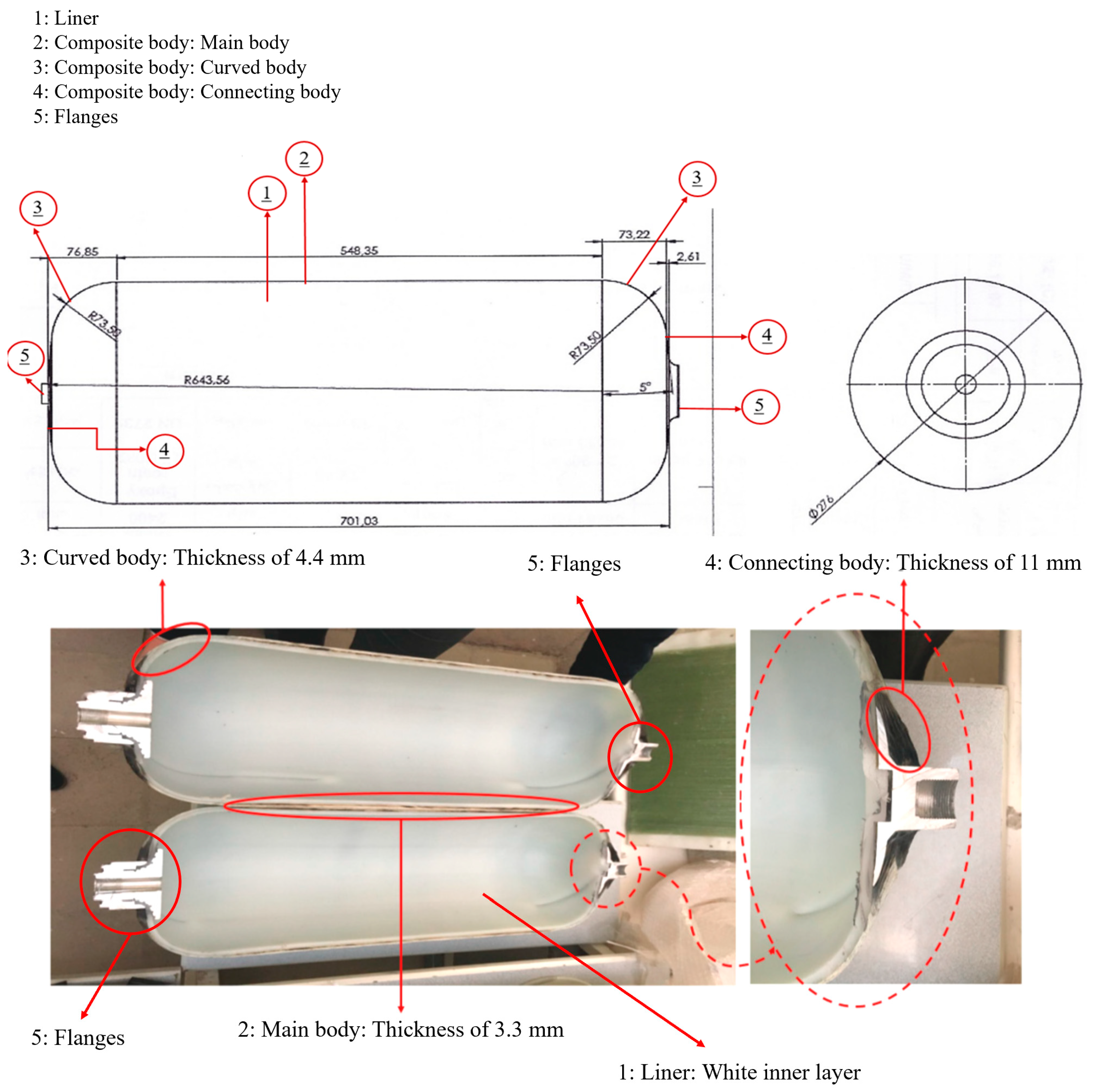
2. Methodology
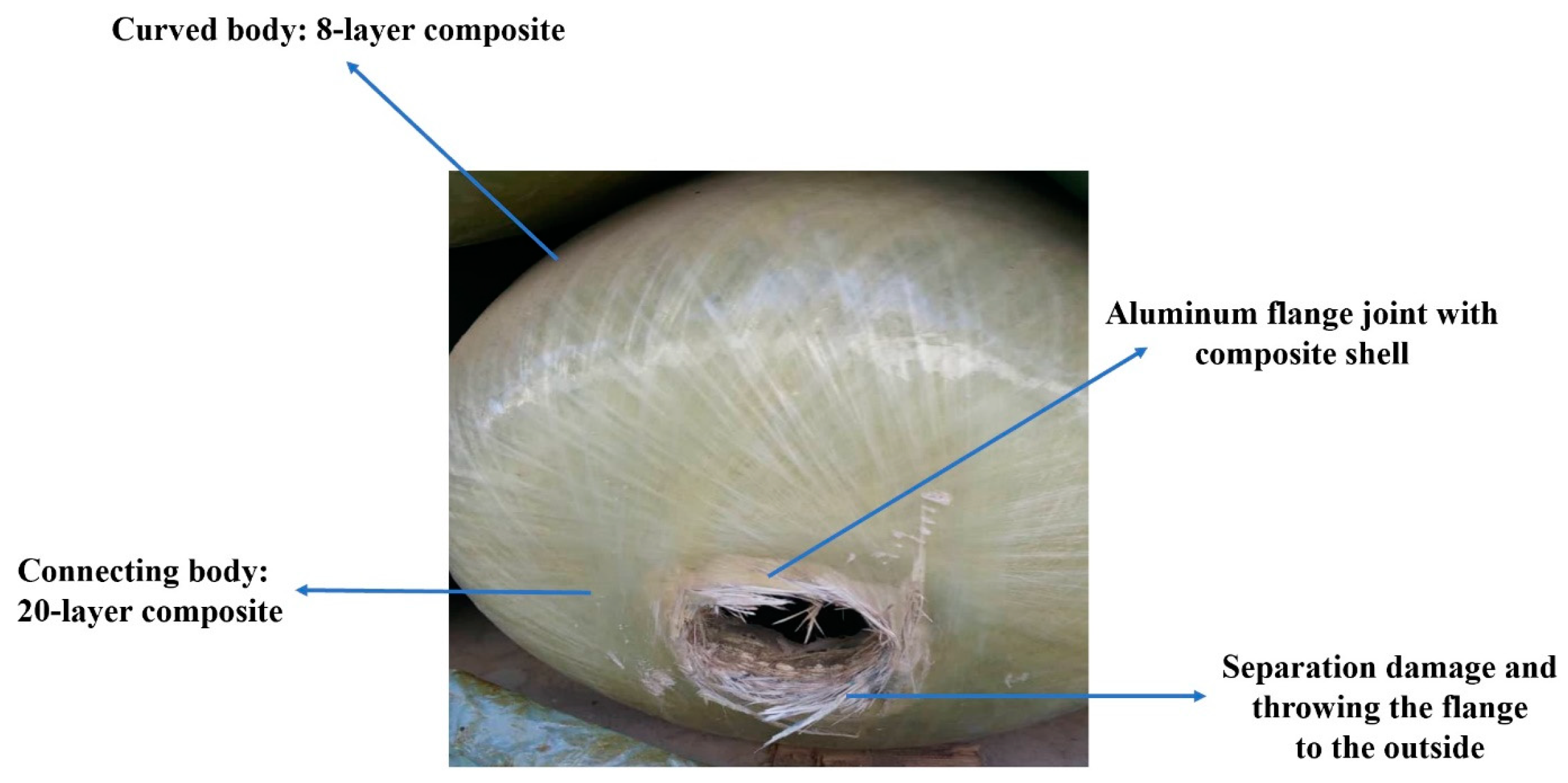
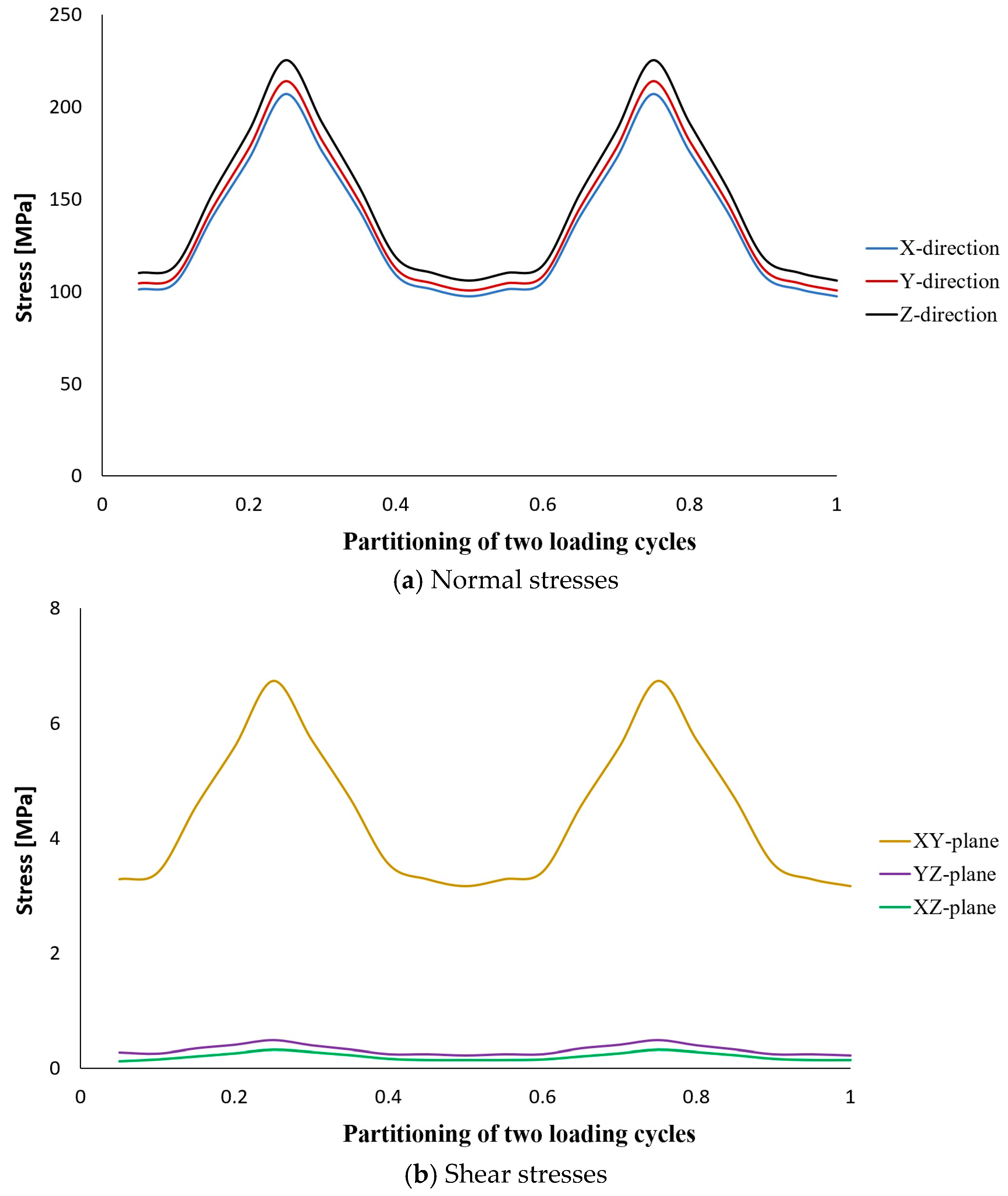
3. Numerical Analysis
4. Results and Discussion
5. Conclusions
- An increase in the load ratio assuming the maximum loading is constant does not have a negative effect on the fatigue life of the tank, and assuming the mean stress is static and constant, the range of dynamic loading changes is reduced.
- Based on the fatigue calculations and the number of loading cycles to failure for the composite material, it can be concluded that the worst condition, the lowest fatigue life, is related to the condition mentioned in the tank strength measurement standard.
- If the service life of the CNG tank is considered based on the mileage of the car, then the behavior of the driver in the refueling process can reduce the service lifetime of the tank by 78% and have significant negative effects.
- It is suggested that the designers of CNG tanks should consider more about using the standards, and sometimes some recommendations are needed to add to the standards and even update the old versions.
- The most important advice to car drivers is to refuel when the CNG tank is completely empty.
Author Contributions
Funding
Institutional Review Board Statement
Informed Consent Statement
Data Availability Statement
Acknowledgments
Conflicts of Interest
References
- Gehandler, J.; Lönnermark, A. CNG vehicle containers exposed to local fires. 2019. [Google Scholar]
- Ou, K.; Zheng, J.; Zhao, Y. Investigation on on-board high-pressure composite tanks subjected to localized and engulfing fire. In Pressure Vessels and Piping Conference; American Society of Mechanical Engineers: New York, NY, USA, 2012; Volume 55089, pp. 201–208. [Google Scholar] [CrossRef]
- Han, B.H.; Yoon, D.J.; Park, C.S.; Lee, Y.S. Impact source location on composite CNG storage tank using acoustic emission energy based signal mapping method. J. Korean Soc. Nondestruct. Test. 2016, 36, 391–398. [Google Scholar] [CrossRef]
- Glisic, B.; Inaudi, D. Health monitoring of full composite CNG tanks using long-gauge fiber optic sensors. In Smart Structures and Materials 2004: Smart Sensor Technology and Measurement Systems; SPIE: San Diego, USA, 2004; Volume 5384, pp. 44–53. [Google Scholar] [CrossRef]
- Saferna, A.; Saferna, P.; Kuczyński, S.; Łaciak, M.; Szurlej, A.; Włodek, T. Thermodynamic Analysis of CNG Fast Filling Process of Composite Cylinder Type IV. Energies 2021, 14, 5568. [Google Scholar] [CrossRef]
- Kim, E.S.; Choi, S.K. Risk analysis of CNG composite pressure vessel via computer-aided method and fractography. Eng. Fail. Anal. 2013, 27, 84–98. [Google Scholar] [CrossRef]
- Kim, E.S.; Kim, J.H.; Moon, B.S.; Goh, J.M. Study on the Structural Safety Evaluation for Pressure Vessel of the CNG Vehicle Using FEM. Adv. Mater. Res. 2012, 569, 598–602. [Google Scholar] [CrossRef]
- Chauhan, G.S.; Awasthi, A. Design and Analysis of high pressure composite vessels. Int. J. Latest Eng. Manag. Res. 2018, 3, 96–102. [Google Scholar]
- Nouri, M.; Ashenai-Ghasemi, F.; Rahimi-Sherbaf, G.; Kashyzadeh, K.R. Experimental and numerical study of the static performance of a hoop-wrapped CNG composite cylinder considering its variable wall thickness and polymer liner. Mech. Compos. Mater. 2020, 56, 339–352. [Google Scholar] [CrossRef]
- Seyedi, S.M.; Naddaf Oskouei, A.; Sayah Badkhor, M. Experimental, numerical and Optimization study of Composite Tanks with Non-Metallic Primer (CNG Fourth Type). Modares Mech. Eng. 2020, 20, 1789–1800. [Google Scholar]
- Nouri, M.; Ashenai-Ghasemi, F.; Rahimi-Sherbaf, G.; Kashyzadeh, K.R. Numerical simulation of CNG fuel tank behavior made of epoxy/glass composite in design mode considering constant and variable thicknesses under burst pressure test. Iran. J. Manuf. Eng. 2021, 8, 20–30. [Google Scholar]
- Debondue, E. Glass composite offers benefits for CNG tanks. Reinf. Plast. 2011, 55, 32–35. [Google Scholar] [CrossRef]
- Kashyzadeh, K.R.; Rahimian Koloor, S.S.; Omidi Bidgoli, M.; Petrů, M.; Amiri Asfarjani, A. An optimum fatigue design of polymer composite compressed natural gas tank using hybrid finite element-response surface methods. Polymers 2021, 13, 483. [Google Scholar] [CrossRef] [PubMed]
- Nouri, M.; Ashenai-Ghasemi, F.; Rahimi-Sherbaf, G.; Kashyzadeh, K.R. Fatigue analysis of a type-IV CNG composite cylinder with variable wall-thickness and polyethylene liner. Mech. Compos. Mater. 2023. [Google Scholar]
- ISO 11439:2000; Gas Cylinders—High Pressure Cylinders for the On-Board Storage of Natural Gas as a Fuel for Automotive Vehicles. 1st ed. International Organization for Standardization: Geneva, Switzerland, 15 September 2000.
- Fawaz, Z.; Ellyin, F. Fatigue failure model for fibre-reinforced materials under general loading conditions. J. Compos. Mater. 1994, 28, 1432–1451. [Google Scholar] [CrossRef]


| Name | Minimum Load (bar) | Maximum Load (bar) | Mean Value (bar) | Loading Ratio |
|---|---|---|---|---|
| SL | 20 | 200 | 110 | 0.1 |
| DB-1 | 38 | 200 | 119 | 0.19 |
| DB-2 | 56 | 200 | 128 | 0.28 |
| DB-3 | 74 | 200 | 137 | 0.37 |
| DB-4 | 92 | 200 | 146 | 0.46 |
| Loading Mode | SL | DB-1 | DB-2 | DB-3 | DB-4 |
|---|---|---|---|---|---|
| Service life of type-IV CNG tank (km) | 4,340,000 | 3,566,000 | 2,703,000 | 1,824,600 | 934,000 |
| Reduction compared to the standard mode (%) | 00.00 | 17.83 | 37.72 | 57.96 | 78.48 |
Disclaimer/Publisher’s Note: The statements, opinions and data contained in all publications are solely those of the individual author(s) and contributor(s) and not of MDPI and/or the editor(s). MDPI and/or the editor(s) disclaim responsibility for any injury to people or property resulting from any ideas, methods, instructions or products referred to in the content. |
© 2023 by the authors. Licensee MDPI, Basel, Switzerland. This article is an open access article distributed under the terms and conditions of the Creative Commons Attribution (CC BY) license (https://creativecommons.org/licenses/by/4.0/).
Share and Cite
Reza Kashyzadeh, K.; Marusin, A.V. Service Life Prediction of Type-IV Composite CNG Cylinder under the Influence of Drivers’ Refueling Habits—A Numerical Study. Polymers 2023, 15, 2480. https://doi.org/10.3390/polym15112480
Reza Kashyzadeh K, Marusin AV. Service Life Prediction of Type-IV Composite CNG Cylinder under the Influence of Drivers’ Refueling Habits—A Numerical Study. Polymers. 2023; 15(11):2480. https://doi.org/10.3390/polym15112480
Chicago/Turabian StyleReza Kashyzadeh, Kazem, and Aleksandr Vyacheslavovich Marusin. 2023. "Service Life Prediction of Type-IV Composite CNG Cylinder under the Influence of Drivers’ Refueling Habits—A Numerical Study" Polymers 15, no. 11: 2480. https://doi.org/10.3390/polym15112480
APA StyleReza Kashyzadeh, K., & Marusin, A. V. (2023). Service Life Prediction of Type-IV Composite CNG Cylinder under the Influence of Drivers’ Refueling Habits—A Numerical Study. Polymers, 15(11), 2480. https://doi.org/10.3390/polym15112480