
Fluorine-Containing, Self-Assembled Graft Copolymer for Tuning the Hydrophilicity and Antifouling Properties of PVDF Ultrafiltration Membranes

Abstract
:1. Introduction
2. Materials and Methods
2.1. Materials
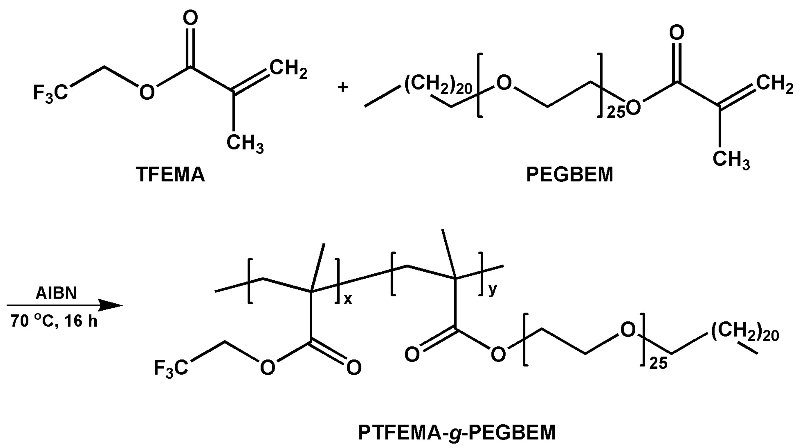
2.2. Synthesis of the PTF Graft Copolymer
2.3. Preparation of UF Membranes
2.4. Characterization of the PTF Graft Copolymer
2.5. Characterization of the PVDF UF Membranes
2.5.1. Morphology and Microstructure
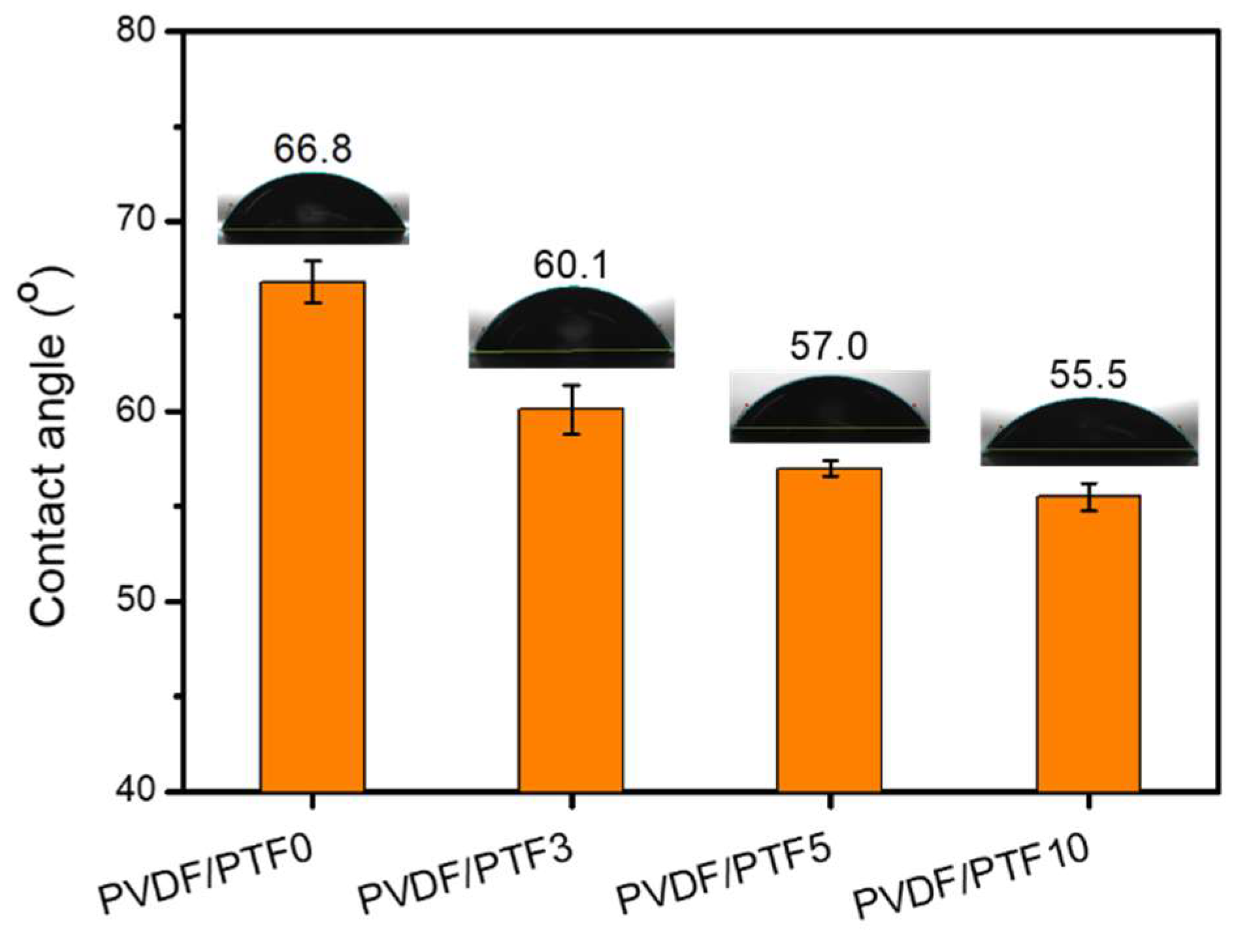
2.5.2. Hydrophilicity of the Membranes’ Surface
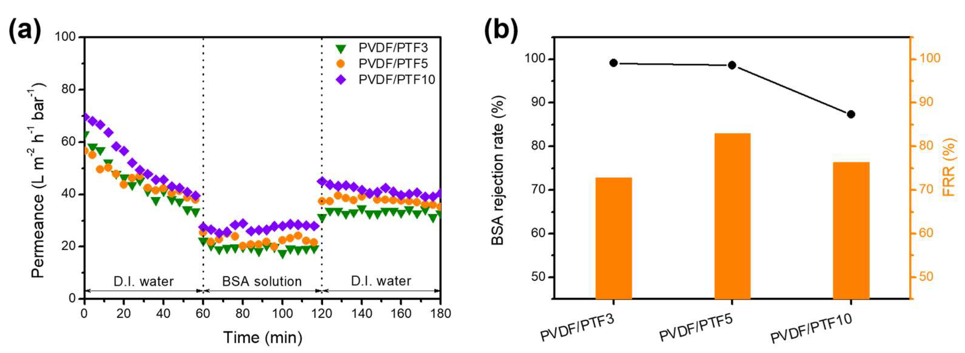
2.5.3. Permeation and Separation Performance
2.5.4. Antifouling Performance
3. Results and Discussion
3.1. Synthesis of the PTF Graft Copolymer
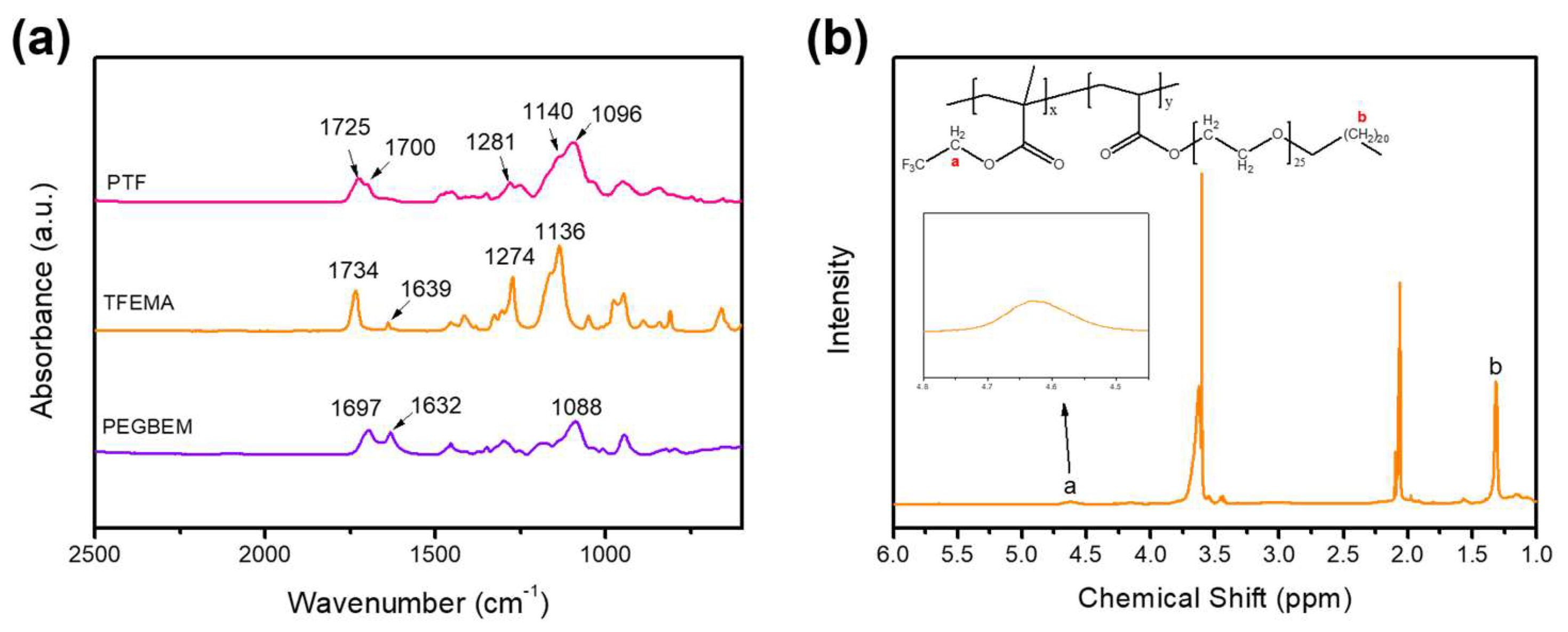
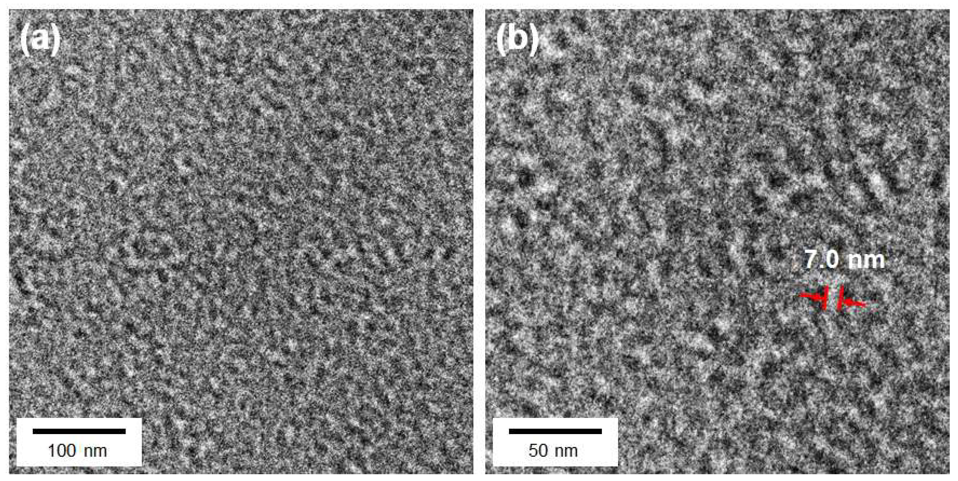
3.2. Structure and Morphology of the PTF Graft Copolymer
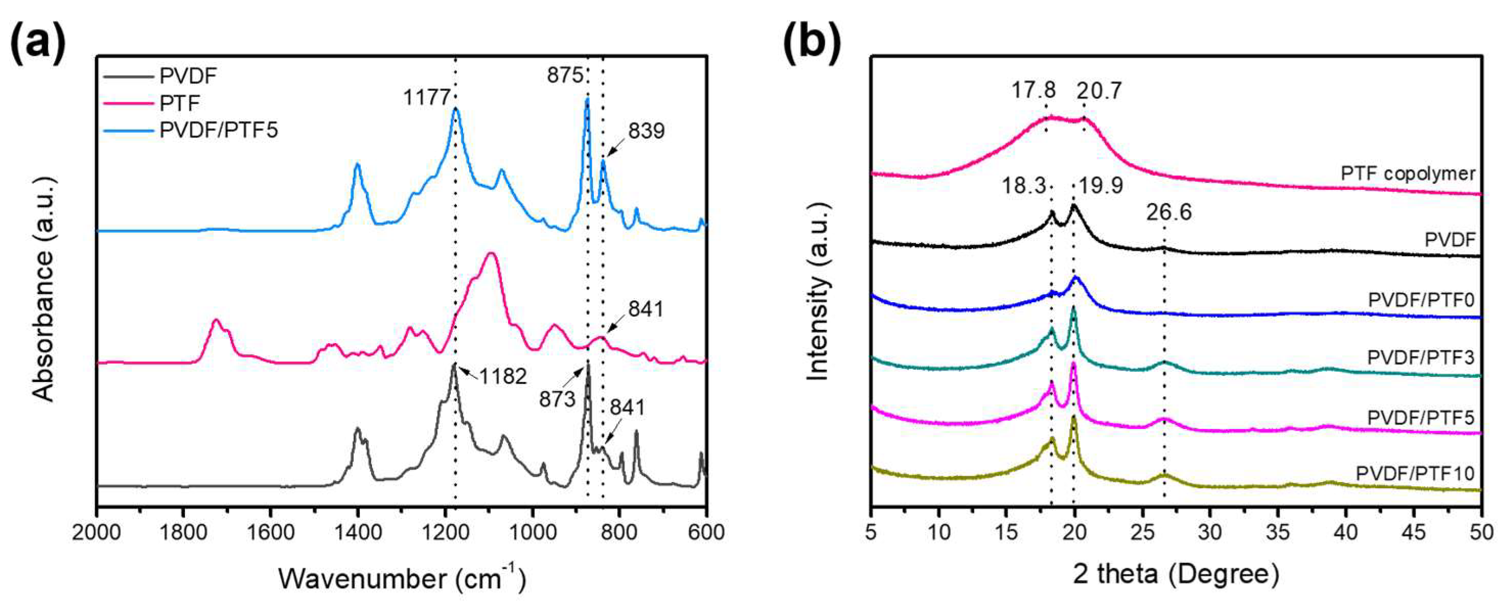
3.3. Preparation and Properties of PVDF/PTF Membranes
3.4. Permeation and Antifouling Properties of the PVDF/PTF Membranes
4. Conclusions
Supplementary Materials
Author Contributions
Funding
Institutional Review Board Statement
Data Availability Statement
Conflicts of Interest
References
- De Guzman, M.R.; Andra, C.K.A.; Ang, M.B.M.Y.; Dizon, G.V.C.; Caparanga, A.R.; Huang, S.-H.; Lee, K.-R. Increased performance and antifouling of mixed-matrix membranes of cellulose acetate with hydrophilic nanoparticles of polydopamine-sulfobetaine methacrylate for oil-water separation. J. Membr. Sci. 2021, 620, 118881. [Google Scholar] [CrossRef]
- Amid, M.; Nabian, N.; Delavar, M. Fabrication of polycarbonate ultrafiltration mixed matrix membranes including modified halloysite nanotubes and graphene oxide nanosheets for olive oil/water emulsion separation. Sep. Purif. Technol. 2020, 251, 117332. [Google Scholar] [CrossRef]
- Samari, M.; Zinadini, S.; Zinatizadeh, A.A.; Jafarzadeh, M.; Gholami, F. A new antifouling metal-organic framework based UF membrane for oil-water separation: A comparative study on the effect of MOF (UiO-66-NH2) ligand modification. Korean J. Chem. Eng. 2022, 39, 3092–3101. [Google Scholar] [CrossRef]
- Ahmad, T.; Guria, C.; Mandal, A. Optimal synthesis of high fouling-resistant PVC-based ultrafiltration membranes with tunable surface pore size distribution and ultralow water contact angle for the treatment of oily wastewater. Sep. Purif. Technol. 2021, 257, 117829. [Google Scholar] [CrossRef]
- Mansor, E.S.; Ali, E.A.; Shaban, A. Tight ultrafiltration polyethersulfone membrane for cheese whey wastewater treatment. Chem. Eng. J. 2021, 407, 127175. [Google Scholar] [CrossRef]
- Yang, M.; Lotfikatouli, S.; Chen, Y.; Li, T.; Ma, H.; Mao, X.; Hsiao, B.S. Nanostructured all-cellulose membranes for efficient ultrafiltration of wastewater. J. Membr. Sci. 2022, 650, 120422. [Google Scholar] [CrossRef]
- Ahsan, A.; Jamil, F.; Rashad, M.A.; Hussain, M.; Inayat, A.; Akhter, P.; Al-Muhtaseb, A.a.H.; Lin, K.-Y.A.; Park, Y. Wastewater from the textile industry: Review of the technologies for wastewater treatment and reuse. Korean J. Chem. Eng. 2023, 40, 2060–2081. [Google Scholar] [CrossRef]
- Zou, D.; Chen, X.; Drioli, E.; Ke, X.; Qiu, M.; Fan, Y. Facile co-sintering process to fabricate sustainable antifouling silver nanoparticles (AgNPs)-enhanced tight ceramic ultrafiltration membranes for protein separation. J. Membr. Sci. 2020, 593, 117402. [Google Scholar] [CrossRef]
- Zhao, J.; Wang, Q.; Yang, J.; Li, Y.; Liu, Z.; Zhang, L.; Zhao, Y.; Zhang, S.; Chen, L. Comb-shaped amphiphilic triblock copolymers blend PVDF membranes overcome the permeability-selectivity trade-off for protein separation. Sep. Purif. Technol. 2020, 239, 116596. [Google Scholar] [CrossRef]
- Ye, Q.; Wang, R.; Chen, C.; Chen, B.; Zhu, X. High-flux pH-responsive ultrafiltration membrane for efficient nanoparticle fractionation. ACS Appl. Mater. Interfaces 2021, 13, 56575–56583. [Google Scholar] [CrossRef]
- Liu, X.; Yuan, H.; Wang, C.; Zhang, S.; Zhang, L.; Liu, X.; Liu, F.; Zhu, X.; Rohani, S.; Ching, C. A novel PVDF/PFSA-g-GO ultrafiltration membrane with enhanced permeation and antifouling performances. Sep. Purif. Technol. 2020, 233, 116038. [Google Scholar] [CrossRef]
- Cheng, K.; Zhang, N.; Yang, N.; Hou, S.; Ma, J.; Zhang, L.; Sun, Y.; Jiang, B. Rapid and robust modification of PVDF ultrafiltration membranes with enhanced permselectivity, antifouling and antibacterial performance. Sep. Purif. Technol. 2021, 262, 118316. [Google Scholar] [CrossRef]
- Fu, W.; Pei, T.; Mao, Y.; Li, G.; Zhao, Y.; Chen, L. Highly hydrophilic poly (vinylidene fluoride) ultrafiltration membranes modified by poly (N-acryloyl glycinamide) hydrogel based on multi-hydrogen bond self-assembly for reducing protein fouling. J. Membr. Sci. 2019, 572, 453–463. [Google Scholar] [CrossRef]
- Alkhouzaam, A.; Qiblawey, H. Novel polysulfone ultrafiltration membranes incorporating polydopamine functionalized graphene oxide with enhanced flux and fouling resistance. J. Membr. Sci. 2021, 620, 118900. [Google Scholar] [CrossRef]
- Zeng, Q.; Wan, Z.; Jiang, Y.; Fortner, J. Enhanced polysulfone ultrafiltration membrane performance through fullerol addition: A study towards optimization. Chem. Eng. J. 2022, 431, 134071. [Google Scholar] [CrossRef]
- Johari, N.A.; Yusof, N.; Lau, W.J.; Abdullah, N.; Salleh, W.N.W.; Jaafar, J.; Aziz, F.; Ismail, A.F. Polyethersulfone ultrafiltration membrane incorporated with ferric-based metal-organic framework for textile wastewater treatment. Sep. Purif. Technol. 2021, 270, 118819. [Google Scholar] [CrossRef]
- Zhang, B.; Wang, W.; Zhu, L.; Li, N.; Chen, X.; Tian, J.; Zhang, X. Simultaneously enhanced permeability and anti-fouling performance of polyethersulfone ultrafiltration membranes by structural control and mixed carbon quantum dots. J. Membr. Sci. 2022, 641, 119931. [Google Scholar] [CrossRef]
- Hosseini, S.M.; Banijamali, M.S.; Farahani, S.K.; Bandehali, S. Enhancing antifouling and separation characteristics of carbon nanofiber embedded poly ether sulfone nanofiltration membrane. Korean J. Chem. Eng. 2022, 39, 2491–2498. [Google Scholar] [CrossRef]
- Sui, Y.; Wang, Z.; Gao, X.; Gao, C. Antifouling PVDF ultrafiltration membranes incorporating PVDF-g-PHEMA additive via atom transfer radical graft polymerizations. J. Membr. Sci. 2012, 413–414, 38–47. [Google Scholar] [CrossRef]
- Zhang, Z.; Zhao, Y.; Luo, X.; Feng, S.; Wu, L. Preparation of a heparin-like functionalized tannic acid-coated polyethersulfone ultrafiltration membrane for hemodialysis by a simple surface modification method. Appl. Surf. Sci. 2022, 572, 151440. [Google Scholar] [CrossRef]
- Revanur, R.; McCloskey, B.; Breitenkamp, K.; Freeman, B.D.; Emrick, T. Reactive amphiphilic graft copolymer coatings applied to poly (vinylidene fluoride) ultrafiltration membranes. Macromolecules 2007, 40, 3624–3630. [Google Scholar] [CrossRef]
- Ganj, M.; Asadollahi, M.; Mousavi, S.A.; Bastani, D.; Aghaeifard, F. Surface modification of polysulfone ultrafiltration membranes by free radical graft polymerization of acrylic acid using response surface methodology. J. Polym. Res. 2019, 26, 231. [Google Scholar] [CrossRef]
- Salimi, P.; Aroujalian, A.; Iranshahi, D. Graft copolymerization of zwitterionic monomer on the polyethersulfone membrane surface by corona air plasma for separation of oily wastewater. Sep. Purif. Technol. 2021, 258, 117939. [Google Scholar] [CrossRef]
- Park, M.S.; Park, B.J.; Kim, N.U.; Park, J.T.; Kim, J.H. Ultrafiltration membranes based on hybrids of an amphiphilic graft copolymer and titanium isopropoxide. J. Appl. Polym. Sci. 2018, 135, 45932. [Google Scholar] [CrossRef]
- Park, B.J.; Kim, N.U.; Ryu, D.Y.; Kim, J.H. P (VDF-co-CTFE)-g-P2VP amphiphilic graft copolymers: Synthesis, structure, and permeation properties. Polym. Adv. Technol. 2019, 30, 2707–2720. [Google Scholar] [CrossRef]
- Bera, A.; Kumar, C.U.; Parui, P.; Jewrajka, S.K. Stimuli responsive and low fouling ultrafiltration membranes from blends of polyvinylidene fluoride and designed library of amphiphilic poly (methyl methacrylate) containing copolymers. J. Membr. Sci. 2015, 481, 137–147. [Google Scholar] [CrossRef]
- Saini, B.; Vaghani, D.; Khuntia, S.; Sinha, M.K.; Patel, A.; Pindoria, R. A novel stimuli-responsive and fouling resistant PVDF ultrafiltration membrane prepared by using amphiphilic copolymer of poly (vinylidene fluoride) and Poly (2-N-morpholino) ethyl methacrylate. J. Membr. Sci. 2020, 603, 118047. [Google Scholar] [CrossRef]
- Wei, Z.; Ling, H.; Junyan, L.; Gang, C.; Na, W. Preparation and properties of core-shell nanosilica/poly(methyl methacrylate-butyl acrylate-2,2,2-trifluoroethyl methacrylate) latex. J. Appl. Polym. Sci. 2011, 120, 1152–1161. [Google Scholar] [CrossRef]
- Park, C.H.; Lee, J.H.; Jung, J.P.; Jung, B.; Kim, J.H. A highly selective PEGBEM-g-POEM comb copolymer membrane for CO2/N2 separation. J. Membr. Sci. 2015, 492, 452–460. [Google Scholar] [CrossRef]
- Moon, S.J.; Min, H.J.; Lee, C.S.; Kang, D.R.; Kim, J.H. Adhesive, free-standing, partially fluorinated comb copolymer electrolyte films for solid flexible supercapacitors. Chem. Eng. J. 2022, 429, 132240. [Google Scholar] [CrossRef]
- Goswami, K.G.; Mete, S.; Chaudhury, S.S.; Sar, P.; Ksendzov, E.; Mukhopadhyay, C.D.; Kostjuk, S.V.; De, P. Self-assembly of amphiphilic copolymers with sequence-controlled alternating hydrophilic–hydrophobic pendant side chains. ACS Appl. Polym. Mater. 2020, 2, 2035–2045. [Google Scholar] [CrossRef]
- Su, L.Y.; Huang, H.H.; Lin, Y.C.; Chen, G.L.; Chen, W.C.; Chen, W.; Wang, L.; Chueh, C.C. Enhancing Long-Term Thermal Stability of Non-Fullerene Organic Solar Cells Using Self-Assembly Amphiphilic Dendritic Block Copolymer Interlayers. Adv. Funct. Mater. 2021, 31, 2005753. [Google Scholar] [CrossRef]
- Lu, C.; Chiang, S.W.; Du, H.; Li, J.; Gan, L.; Zhang, X.; Chu, X.; Yao, Y.; Li, B.; Kang, F. Thermal conductivity of electrospinning chain-aligned polyethylene oxide (PEO). Polymer 2017, 115, 52–59. [Google Scholar] [CrossRef]
- Li, J.; Meng, Q.; Li, W.; Zhang, Z. Influence of crystalline properties on the dielectric and energy storage properties of poly(vinylidene fluoride). J. Appl. Polym. Sci. 2011, 122, 1659–1668. [Google Scholar] [CrossRef]
- Barrau, S.; Ferri, A.; Da Costa, A.; Defebvin, J.; Leroy, S.; Desfeux, R.; Lefebvre, J.M. Nanoscale Investigations of alpha- and gamma-Crystal Phases in PVDF-Based Nanocomposites. ACS Appl. Mater. Interfaces 2018, 10, 13092–13099. [Google Scholar] [CrossRef]
- Cai, X.; Lei, T.; Sun, D.; Lin, L. A critical analysis of the α, β and γ phases in poly(vinylidene fluoride) using FTIR. RSC Adv. 2017, 7, 15382–15389. [Google Scholar] [CrossRef]
- Almaie, S.; Vatanpour, V.; Rasoulifard, M.H.; Dorraji, M.S.S. Novel negatively-charged amphiphilic copolymers of PVDF-g-PAMPS and PVDF-g-PAA to improve permeability and fouling resistance of PVDF UF membrane. React. Funct. Polym. 2022, 179, 105386. [Google Scholar] [CrossRef]
- Liu, L.; Huang, L.; Shi, M.; Li, W.; Xing, W. Amphiphilic PVDF-g-PDMAPMA ultrafiltration membrane with enhanced hydrophilicity and antifouling properties. J. Appl. Polym. Sci. 2019, 136, 48049. [Google Scholar] [CrossRef]
- Koh, J.K.; Kim, Y.W.; Ahn, S.H.; Min, B.R.; Kim, J.H. Antifouling poly (vinylidene fluoride) ultrafiltration membranes containing amphiphilic comb polymer additive. J. Polym. Sci. Part B Polym. Phys. 2010, 48, 183–189. [Google Scholar] [CrossRef]
- Cuperus, F.; Bargeman, D.; Smolders, C. Permporometry: The determination of the size distribution of active pores in UF membranes. J. Membr. Sci. 1992, 71, 57–67. [Google Scholar] [CrossRef]
- Agarwal, C.; Das, S.; Pandey, A.K. Study on pore size distributions of microporous polymer membranes having different physical architecture using capillary flow porometry. Mater. Today Chem. 2022, 23, 100652. [Google Scholar] [CrossRef]
- Yong, M.; Zhang, Y.; Sun, S.; Liu, W. Properties of polyvinyl chloride (PVC) ultrafiltration membrane improved by lignin: Hydrophilicity and antifouling. J. Membr. Sci. 2019, 575, 50–59. [Google Scholar] [CrossRef]
- Abdollahi, E.; Heidari, A.; Mohammadi, T.; Asadi, A.A.; Tofighy, M.A. Application of Mg-Al LDH nanoparticles to enhance flux, hydrophilicity and antifouling properties of PVDF ultrafiltration membrane: Experimental and modeling studies. Sep. Purif. Technol. 2021, 257, 117931. [Google Scholar] [CrossRef]
- Roy, S.; Bhalani, D.V.; Jewrajka, S.K. Surface segregation of segmented amphiphilic copolymer of poly (dimethylsiloxane) and poly (ethylene glycol) on poly (vinylidene fluoride) blend membrane for oil–water emulsion separation. Sep. Purif. Technol. 2020, 232, 115940. [Google Scholar] [CrossRef]
- Hashim, N.A.; Liu, F.; Li, K. A simplified method for preparation of hydrophilic PVDF membranes from an amphiphilic graft copolymer. J. Membr. Sci. 2009, 345, 134–141. [Google Scholar] [CrossRef]
- Park, S.-H.; Ahn, Y.; Jang, M.; Kim, H.-J.; Cho, K.Y.; Hwang, S.S.; Lee, J.-H.; Baek, K.-Y. Effects of methacrylate based amphiphilic block copolymer additives on ultra filtration PVDF membrane formation. Sep. Purif. Technol. 2018, 202, 34–44. [Google Scholar] [CrossRef]
- Shen, J.; Zhang, Q.; Yin, Q.; Cui, Z.; Li, W.; Xing, W. Fabrication and characterization of amphiphilic PVDF copolymer ultrafiltration membrane with high anti-fouling property. J. Membr. Sci. 2017, 521, 95–103. [Google Scholar] [CrossRef]
- Zhao, J.; Han, H.; Wang, Q.; Yan, C.; Li, D.; Yang, J.; Feng, X.; Yang, N.; Zhao, Y.; Chen, L. Hydrophilic and anti-fouling PVDF blend ultrafiltration membranes using polyacryloylmorpholine-based triblock copolymers as amphiphilic modifiers. React. Funct. Polym. 2019, 139, 92–101. [Google Scholar] [CrossRef]


| Membrane | PVDF (g) | PEG (g) | PTF (g) | THF (mL) | DMF (mL) |
|---|---|---|---|---|---|
| PVDF/PTF0 | 0.85 | 0.15 | - | 2.28 | 2.28 |
| PVDF/PTF3 | 0.82 | 0.15 | 0.03 | 2.28 | 2.28 |
| PVDF/PTF5 | 0.80 | 0.15 | 0.05 | 2.28 | 2.28 |
| PVDF/PTF10 | 0.75 | 0.15 | 0.1 | 2.28 | 2.28 |
| Membrane | Mean Flow Pore Size (nm) | Smallest Pore Size (nm) |
|---|---|---|
| PVDF/PTF3 | 55.5 | 39.1 |
| PVDF/PTF5 | 60.5 | 39.3 |
| PVDF/PTF10 | 73.1 | 42.0 |
| Membrane | 1st Water Permeance (L m−2 h−1 bar−1) | BSA Permeance (L m−2 h−1 bar−1) | 2nd Water Permeance (L m−2 h−1 bar−1) | BSA Rejection (%) | FRR (%) |
|---|---|---|---|---|---|
| PVDF/PTF3 | 44.7 | 19.3 | 32.6 | 99.1 | 72.9 |
| PVDF/PTF5 | 45.4 | 21.9 | 37.7 | 98.6 | 83.0 |
| PVDF/PTF10 | 54.1 | 26.7 | 41.3 | 87.3 | 76.4 |
| Membrane | Increase in Modifier Content (%) | Relative Increase in Percentage Flux (%) | Relative Increase in Percentage BSA Rejection (%) | Relative Increase in Percentage FRR (%) | Type of Filtration Test | Reference |
|---|---|---|---|---|---|---|
| PVDF/PVDF-g-PAA | 6.6 | 14.7 | 0.2 | 6.7 | Dead-end | [37] |
| PVDF/PVDF-g-PDMAPMA | 4.7 | 36.1 | 0.5 | 3.4 | Cross-flow | [38] |
| PVDF/PMMA-b-PPEGMA | 2.0 | 6.1 | - | 3.8 | Cross-flow | [46] |
| PVDF/PTF | 2.6 | 15.6 | −0.5 | 13.9 | Cross-flow | This work |
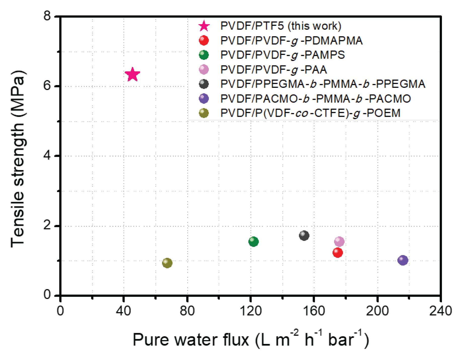
| Membrane | Pure Water Flux (L m−2 h−1 bar−1) | BSA Rejection (%) | Tensile Strength (MPa) | Elongation at Break (%) | Type of Filtration Test | Reference |
|---|---|---|---|---|---|---|
| PVDF/PPEGMA-b-PMMA-b-PPEGMA | 154 | 100 | 1.72 | - | Cross-flow | [9] |
| PVDF/PVDF-g-PAMPS | 122 | 98.5 | 1.55 | 120 | Dead-end | [37] |
| PVDF/PVDF-g-PAA | 176 | 98.0 | 1.55 | 100.8 | Dead-end | [37] |
| PVDF/PVDF-g-PDMAPMA | 175 | 94.3 | 1.22 | 31.5 | Cross-flow | [38] |
| PVDF/P(VDF-co-CTFE)-g-POEM | 67.4 | 99.0 | 0.92 | 93.7 | Dead-end | [39] |
| PVDF/PACMO-b-PMMA-b-PACMO | 216 | 98.9 | 1.0 | 7.8 | Cross-flow | [48] |
| PVDF/PTF5 | 45.4 | 98.6 | 6.34 | 47.8 | Cross-flow | This work |
Disclaimer/Publisher’s Note: The statements, opinions and data contained in all publications are solely those of the individual author(s) and contributor(s) and not of MDPI and/or the editor(s). MDPI and/or the editor(s) disclaim responsibility for any injury to people or property resulting from any ideas, methods, instructions or products referred to in the content. |
© 2023 by the authors. Licensee MDPI, Basel, Switzerland. This article is an open access article distributed under the terms and conditions of the Creative Commons Attribution (CC BY) license (https://creativecommons.org/licenses/by/4.0/).
Share and Cite
Moon, S.J.; Kim, Y.J.; Kang, D.R.; Lee, S.Y.; Kim, J.H. Fluorine-Containing, Self-Assembled Graft Copolymer for Tuning the Hydrophilicity and Antifouling Properties of PVDF Ultrafiltration Membranes. Polymers 2023, 15, 3623. https://doi.org/10.3390/polym15173623
Moon SJ, Kim YJ, Kang DR, Lee SY, Kim JH. Fluorine-Containing, Self-Assembled Graft Copolymer for Tuning the Hydrophilicity and Antifouling Properties of PVDF Ultrafiltration Membranes. Polymers. 2023; 15(17):3623. https://doi.org/10.3390/polym15173623
Chicago/Turabian StyleMoon, Seung Jae, Young Jun Kim, Du Ru Kang, So Youn Lee, and Jong Hak Kim. 2023. "Fluorine-Containing, Self-Assembled Graft Copolymer for Tuning the Hydrophilicity and Antifouling Properties of PVDF Ultrafiltration Membranes" Polymers 15, no. 17: 3623. https://doi.org/10.3390/polym15173623