1. Introduction
A common practice to evaluate polymers for their suitability in engineering applications is to quantify their mechanical properties such as elastic modulus and yield strength using coupon specimens. This approach has also been adopted for investigating the influence of chemical solvents on the mechanical properties, especially for resisting the environmental stress cracking (ESC) e.g., [
1,
2]. However, due to the long duration required for the specimen treatment in order to saturate the chemical solvents in the specimens, and the possibility of mass loss due to material dissolved in the chemical solvents, specimens used in the mechanical testing are usually not fully saturated with the chemical solvents, nor are the chemical solvents distributed uniformly in the specimens. As a result, clear conclusions could not be drawn from the testing in order to characterize the influence of chemical solvents on ESC resistance of polymers.
This paper is concerned with failure of chlorinated poly(vinyl chloride) (CPVC) pipe caused by the exposure to chemical solvents. Primer and acetone were used as the chemical solvents in the study. The former is a commercial product that has been widely used to clean and soften CPVC pipe surface before joining in a solvent welding process [
3], and is a mixture of acetone, methyl ethyl ketone (MEK), cyclohexanone (CYH) and tetrahydrofuran (THF) [
4] with acetone as the major component. Although the primer has been used for many years, some people are still concerned about its use in joining CPVC pipes, as some solvents in the primer were suspected to be responsible for the ductility decrease of the pipe [
5].
Since primer is used to soften surface layer of CPVC pipe before the joining, primer acts as a plasticizer [
6], and thus it has been suspected that the use of primer may introduce ESC in the CPVC pipe. However, the role of primer on the CPVC pipe failures has attracted little attention so far, even though ESC in CPVC pipe has been reported in the literature [
7,
8].
For acetone, it has been included in a recently updated list of chemicals which could cause cracking during CPVC pipe installation at freezing temperatures [
9]. Although such a list is mainly for the purpose of precaution, it also motivated us to clarify the role of acetone on the crack generation in CPVC pipe. Moreover, the lack of specific details for the cause of cracking could lead to uncertainty on the guidance for the proper practice of joining CPVC pipe, resulting in a significant variation in the actual service life of the pipe from the designed service life of 50 years.
It should be noted that in an early study by Yue [
10], suitable chemical solvents for solvent welding have been suggested to be the solvents that can dissolve the polymer to form a surface layer of gel of highly mobile molecular chains, and do not need to be rapidly diffused into the polymer. Although plenty of studies have supported such an idea [
1,
11,
12], none of the studies considered possible issues generated by the presence of excessive chemical solvents that could be left on the pipe surface but not later covered by adhesives to bond with a matching surface. At present, it is not clear whether the presence of such a surface could have any adverse effect on the strength and integrity of the bonded pipe assembly. The study presented here was designed to examine the mechanical performance of CPVC that has been in touch with primer or acetone, either to form a soft layer on the surface or to diffuse through the whole thickness, to elucidate the influence of the exposure on the mechanical properties of CPVC.
This study is part of a project for development of a new method to quantify mechanical performance of CPVC pipe joints, especially after the solvent welding process. This paper is to examine the mechanical properties for CPVC and its pipe products after exposure to either primer or acetone, and to compare the mechanical properties with those for virgin specimens, i.e., without any exposure to the chemical solvents.
3. Results and Discussion
Figure 3 summarizes the percentage of weight gain for the dog-bone specimens as a function of drying time after the immersion either in acetone for 40 min,
Figure 3a, or in primer for 10 min,
Figure 3b. As shown in these figures, initial amount of acetone absorbed in the specimens was more than twice of the amount of primer. However, after the air-dry process, the residual acetone left in the specimens was about 2 wt% of the virgin specimens, much less than the residual primer of around 9 wt%, even though the maximum drying time for the specimens immersed in acetone was less than half of the drying time for the specimens immersed in primer. Note that each point in
Figure 3 represents the average value from at least three specimens. Error bars were also included in
Figure 3 to indicate the range from minimum to maximum values, but the ranges were smaller than the size of the markers for the average values, except the second point from the left in
Figure 3b.
Figure 4 summarizes mechanical test results for dog-bone specimens.
Figure 4a,c present the typical engineering stress-stroke curves for specimens with different drying time (as shown by the numbers in each figure), after immersion in acetone and primer, respectively, and
Figure 4b,d the corresponding average values for yield stress and fracture stroke, each from two specimens, as functions of drying time, including values for the virgin specimens as a reference. Data in
Figure 4 suggest a general trend that yield stress increases and fracture stroke decreases with the increase of drying time. However, after a given air drying period, specimens immersed in acetone showed higher yield stress than specimens treated in primer, filled squares in
Figure 4b,d, respectively, and both yield stress values were lower than the yield stress for virgin specimens. As shown in
Figure 3, difference of the yield stresses was because both acetone and primer acted as plasticizers for CPVC. With a lower plasticizer content, drop of the yield stress for the dog-bone specimens was smaller. In addition, after air dry for 984 h, yield stress in
Figure 4b was higher than the corresponding value in
Figure 4d after air dry for 2230 h. This also suggests that acetone was much easier than primer to remove from CPVC. This is consistent with the change of weight gain shown in
Figure 3. That is, residual acetone content was much lower than residual primer content, even though the former was after a shorter air-dry period. Unfilled circles in
Figure 4b,d also suggest that ductility change in terms of stroke for the onset of fracture showed the opposite trend to that for yield stress. That is, comparing fracture stroke for specimens treated in primer after air dry of 2230 h,
Figure 4d, with those treated in acetone after air dry of 984 h,
Figure 4b, the former was larger than the latter even after a longer drying period, and both were larger than that for the virgin specimens (about 2.5 mm). This trend could also be explained by the plasticizer effect and the higher residual primer content than the acetone content.
In addition to the trends for yield stress and fracture stroke in
Figure 4b,d, engineering stress-stroke curves shown in
Figure 4a,c also indicate that with a short drying time, i.e., less than 6 h in
Figure 4a and 312 h in
Figure 4c for specimens immersed in acetone and primer, respectively, these curves do not show any peak stress. This suggests that these specimens deformed uniformly through the whole gauge section till the end of test without fracture, and that residual acetone and primer in the specimens were sufficient to act as a plasticizer to allow large deformation without crack initiation. Therefore, degradation was not introduced to CPVC by immersion in these chemical solvents. Note that all mechanical tests, except the curve with drying time of 312 h in
Figure 4c, were stopped when the stroke reached 10 mm. Therefore, specimens after drying periods of 2.5, 6 and 23 h in
Figure 4a, and 96 and 312 h in
Figure 4c did not fracture at the end of the tests.
Figure 5 presents typical engineering stress-stroke curves for pipe ring specimens after either the full immersion treatment (FI),
Figure 5a, or through the local contact (LC) on the inner surface,
Figure 5b. ‘A’ in the curve labels in
Figure 5 stands for acetone, ‘P’ primer, and ‘0.5′ and ‘2.5′ time in hours for full immersion and local contact, respectively. For example, the curve labelled as ‘FI-P-0.5′ in
Figure 5a was from a specimen after full immersion in primer for 0.5 h. Note that as mentioned earlier, all pipe ring specimens were air dried for 10.5 days prior to the mechanical testing, to be consistent with one of the drying periods used in the previous study [
13].
Figure 5 also includes a reference curve (using a dashed line) which was from a virgin specimen without any treatment.
Figure 5a suggests that after the immersion-and-air dry process, the pipe ring specimens treated in primer (FI-P-0.5) had a much lower yield stress than that for the virgin specimens, consistent with the results reported previously [
13]. However, for the pipe ring specimens treated in acetone and then air dried for 10.5 days, as shown by the curve FI-A-0.5 in
Figure 5a, yielding could occur at the same stress level as the virgin specimens, though ductility in terms of fracture stroke was reduced. The possibility of recovery of the maximum stress to the level for the virgin specimens also suggests that acetone could easily be removed from CPVC, and that the air dry for 10.5 days was sufficient to reduce the acetone content in the pipe ring specimen to a negligible level, to avoid its effect on the yield stress of the material, though a detailed investigation using a large number of specimens would be needed to determine the critical drying time needed after the immersion treatment in acetone to reach a full recovery of the yield stress for the specimens.
The corresponding pipe ring specimens treated through local contact with acetone and then air dried for 10.5 days, as shown by LC-A-2.5 in
Figure 5b, also showed the same yield stress level as that for the virgin specimens. However, the corresponding specimens treated in primer and then air dried for 10.5 days, i.e., either FI-P-0.5 in
Figure 5a or LC-P-2.5 in
Figure 5b, the peak stress was much lower than that for the virgin specimens. As the curve for LC-P-2.5 in
Figure 5b shows a sudden drop of the engineering stress while the curve was following the path of load increase of the virgin specimen, and the specimen fractured in a brittle manner, the LC-P-2.5 specimen was fractured before yielding could be generated. Although the change from a ductile, post-yield fracture for the virgin specimens, to the brittle, prior-to-yield fracture after the treatment in primer could be interpreted as a ductile-brittle transition, it needs to be pointed out that the specimens with the ‘local-contact’ treatment could not be fully saturated with the primer on the cross section where the local contact with primer was made. Rather, primer was partially absorbed on the cross section and thus, the cross section had a two-layered structure in which only the layer close to the inner surface contained primer [
13]. In view of such a two-layered structure on the cross section, rather than referring this change of fracture behavior as a ductile–brittle transition, other possible reasons for its occurrence, such as the interaction between the relatively soft, low strength inner layer and the stiff, high strength outer layer, should be considered. Only after these reasons are ruled out could we consider this phenomenon as a ductile-brittle transition. Note that both plots in
Figure 5b for specimens after the local contact treatment also indicate that after the drying period of 10.5 days, initial slope of the engineering stress-stroke curves became similar to that for the virgin specimens, suggesting that after air dry of 10.5 days, the inner layer in both LC-P-2.5 and LC-A-2.5 has gained sufficient stiffness to show little effect of the residual chemical solvents on the overall specimen stiffness.
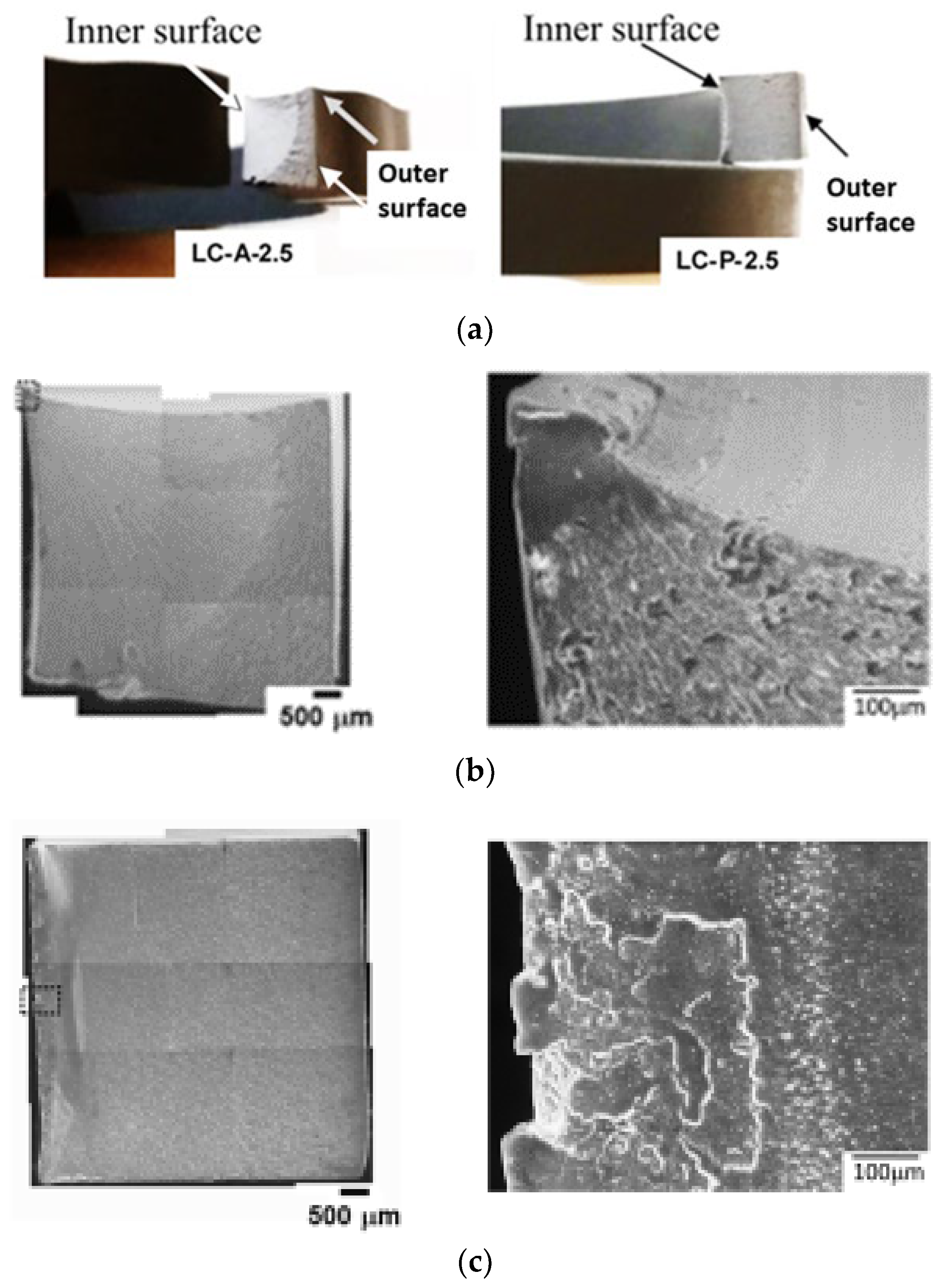
To further investigate the fracture behavior of the pipe ring specimens treated through local contact with either primer or acetone on the inner surface, fracture behaviors of these specimens were inspected microscopically, as presented in
Figure 6.
Figure 6a presents optical photographs, showing the overall fracture surfaces before the SEM examination. The left photograph in
Figure 6a was from a post-tested LC-A-2.5 specimen, showing a fan-shaped area that was generated from a corner near the inner surface, and the right photograph from LC-P-2.5, showing a narrow band along the vertical direction, generated across the edge along the inner surface.
The corresponding SEM micrographs for
Figure 6a are shown in
Figure 6b for LC-A-2.5, and
Figure 6c for LC-P-2.5. Left micrographs in
Figure 6b,c are composite micrographs, by combining many SEM micrographs at the same magnification to show the overall fracture surfaces. SEM micrographs of relatively high magnification for the regions boxed in the left composite micrographs using dash lines, are presented on the right of
Figure 6b,c, depicting the flat crack initiation zones which do not show any sign of crack initiation from a dominant defect. This is an indication of ESC [
14]. Since crack initiation in LC-A-2.5 started after the yielding, but that in LC-P-2.5 before, as indicated by the relative stroke position for the sudden stress drop with respect to the stroke for the maximum stress, the region where crack was initiated in the former was smooth while that in the latter consisted of multiple flat regions with slightly different elevations.
Another difference between
Figure 6b,c is the extent of stable crack growth before the transition to relatively fast crack growth. The left, composite micrograph in
Figure 6b shows that the crack started from a corner of the cross section near the inner surface, which grew in a stable manner to form a fan shape with area covering more than half of the cross section before the fast growth. The corresponding micrograph in
Figure 6c, on the other hand, shows crack initiation along the edge adjacent to the inner surface, which led to fracture through a relatively fast crack growth, resulting in a sudden stress drop shown by the curve of LC-P-2.5 in
Figure 5b. Features on the fracture surfaces to indicate ductile and brittle behaviors and the transition from stable to fast crack growth have been well documented in Ref. [
15]
Note that the fan-shaped region shown in the left micrograph of
Figure 6b is consistent with the observation reported previously, i.e., Figure 9a in ref. [
13] for dry (virgin) specimens. This suggested that after a drying period of 10.5 days, LC-A-2.5 could fracture in a manner similar to the virgin specimens.
For LC-P-2.5, the absorption of primer through the inner surface (i.e., the left edge on the cross section of
Figure 6c) resulted in a left part of the cross section with a reduced yield stress. Although
Figure 4d suggests that decrease of yield stress could be accompanied by the increase of fracture ductility, the fracture surface shown in
Figure 6c suggests that crack started from the region of low yield stress. Therefore, it is speculated that the high fracture ductility of the region has been suppressed by the adjacent region that has high yield stress and low fracture ductility. Growth of the crack to the adjacent region of high yield stress and low ductility resulted in the brittle fracture. Godart and Leevers [
16] discussed possible fracture scenarios in a bi-layered polymer structure. However, the discussion was focused on the crack initiation in the thin, brittle layer, and crack growth into the tough substrate to result in a brittle fracture, rather than the ductile fracture for the pure substrate without the thin, brittle layer. To our knowledge, the scenario of crack initiation from the region of low yield stress and high ductility has not been investigated in the past. We speculate that ductility of the low yield-stress layer is suppressed due to its bonding to the high strength and stiff substrate. Therefore, the overall fracture behavior is brittle, as shown by the LC-P-2.5 specimens. However, such a speculation needs to be verified in a future study.
Results from the pipe ring specimens presented in
Figure 6 also suggest that after the exposure to primer, the specimens show a bigger reduction in strength and ductility than those exposed to acetone. Therefore, if excessive amount of primer was applied in the solvent welding process, to result in primer on some inner surface of the pipe which was not covered by adhesives, there could be an adverse effect on the mechanical properties of the CPVC pipe. In other words, primer applied in solvent welding process could actually reduce the load-carrying capability of the CPVC pipe. Although in the bonding assembly, reduction in the mechanical performance of CPVC could be offset by the load-carrying enhancement from the matching counterpart, such an offset benefit does not exist for the CPVC pipe section that is in contact with the excessive primer and is not part of the bonding assembly. This scenario could not be avoided, especially in an environment of low temperature or in a welding process that needs a relatively long time to complete, resulting in decrease of strength and ductility of CPVC. This could lead to generation of micro-cracks from the inner surface of the pipe, especially for pipes with a relatively high residual stress [
17] or made of CPVC resin of relatively low molecular weight. These micro-cracks could evolve over time to cause premature pipe failure.


