
Novel Polymer Composites for Lead-Free Shielding Applications

 , ,
, ,
Abstract
1. Introduction
2. Materials and Methods
2.1. Materials
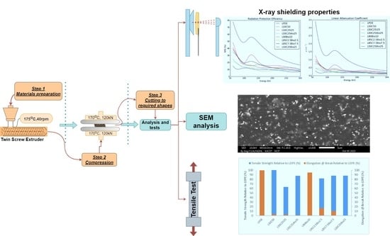
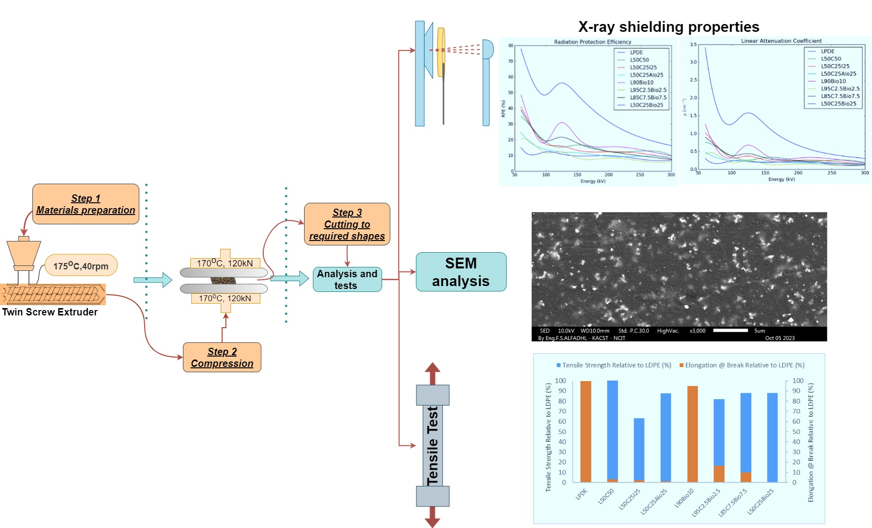
2.2. Methodology
- Weighing the materials: Utilize an electrical balance (Sartorius Analytical, Karlsruhe, Germany) with an accuracy of ±0.0001 g to weigh the samples.
- Mixing Process:
- 1.
- Use an internal mixer (Internal mixer 350 S, Brabender, Duisburg, Germany) set at 175 °C.
- 2.
- Begin mixing LDPE alone.
- 3.
- Gradually increase the rotation speed from 40 RPM to achieve the best mixing results, increasing in 5 RPM increments.
- 4.
- Introduce fillers gradually after reaching maximum speed.
- 5.
- Continue mixing for 10 min.
- Rolling the Mixture:
- 6.
- Employ a two-roll mill (Prep-Mill, Brabender, Duisburg, Germany) set at 170 °C and 30 RPM.
- 7.
- Roll the mixture for 2–5 min.
- 8.
- Allow the mixture to cool.
- Shaping and Pressing:
- 9.
- Cut the mixture into pieces in preparation for the pressing machine (P400 PM, Collin, Germany).
- 10.
- Use a stainless-steel frame measuring 100 × 100 × 2 mm3 to shape the sample.
- 11.
- Press the sample at 170 °C, starting at 30 kN and gradually increasing up to 120 kN over 10 min.
- 12.
- Let the sample cool at room temperature.
- Preparing Testing Samples:
- 13.
- Cut the sample into required shapes for testing, such as discs for shielding and dumbbell shapes for tensile and other tests.
3. Characterization
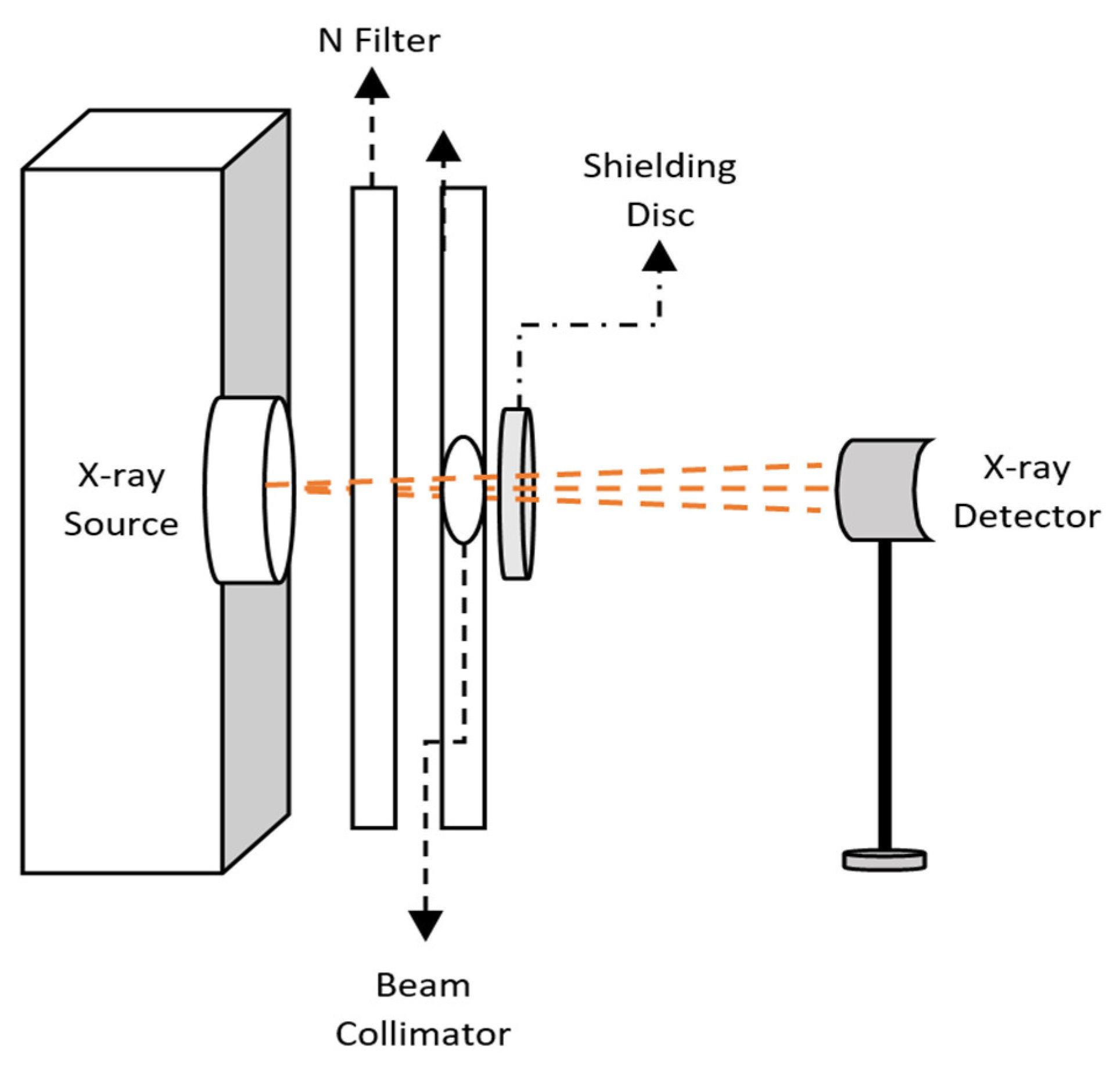
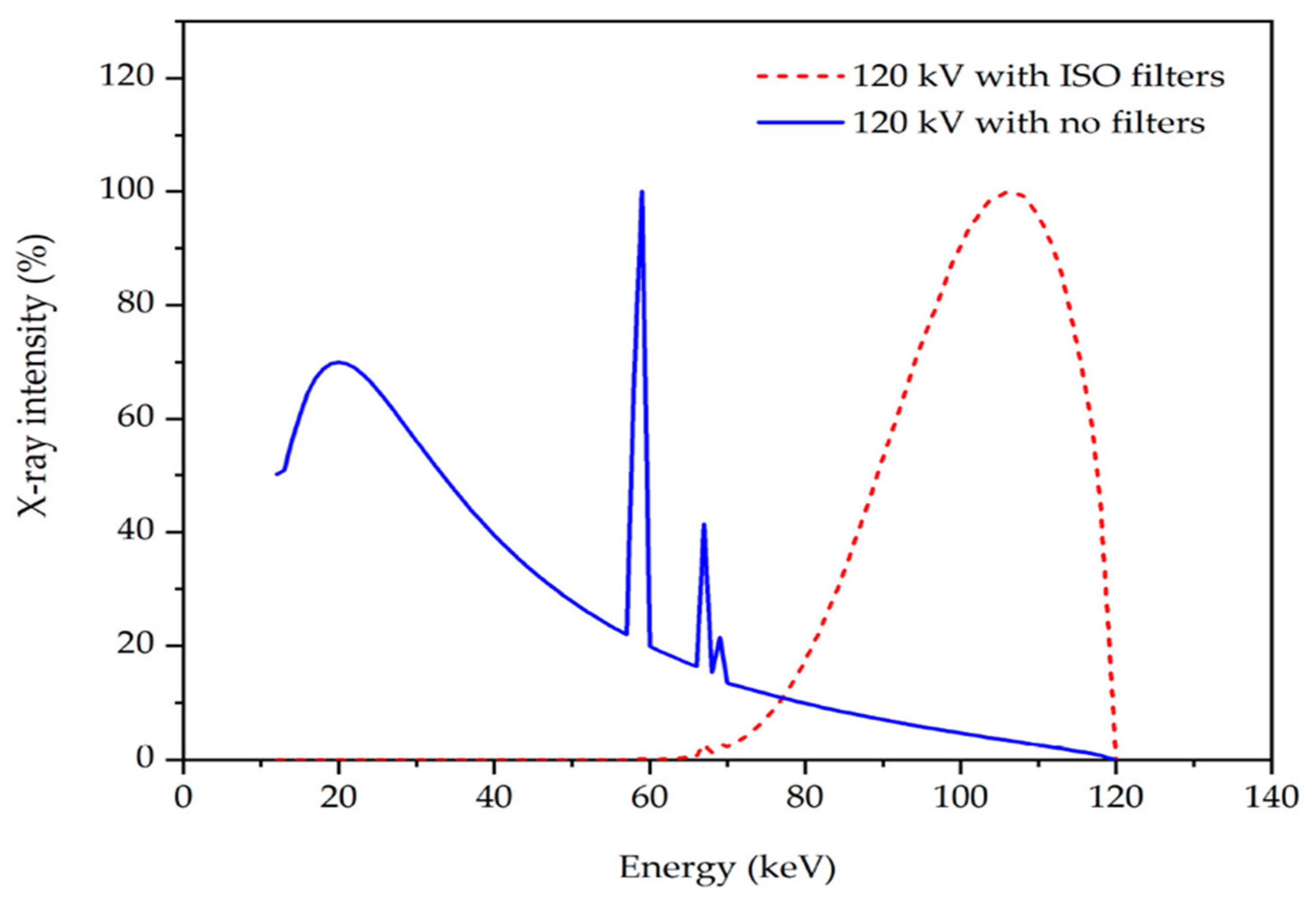
3.1. X-ray Test
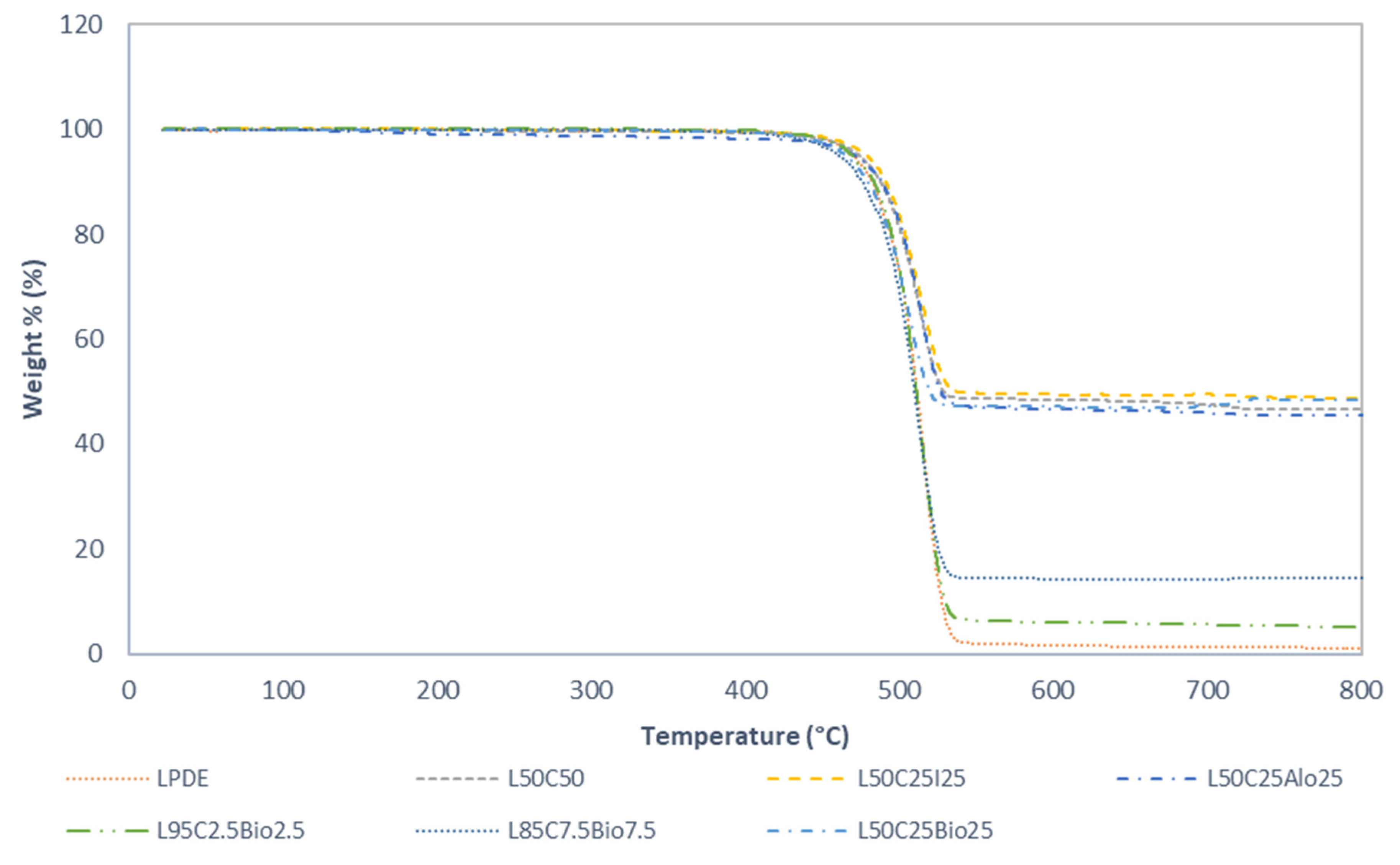
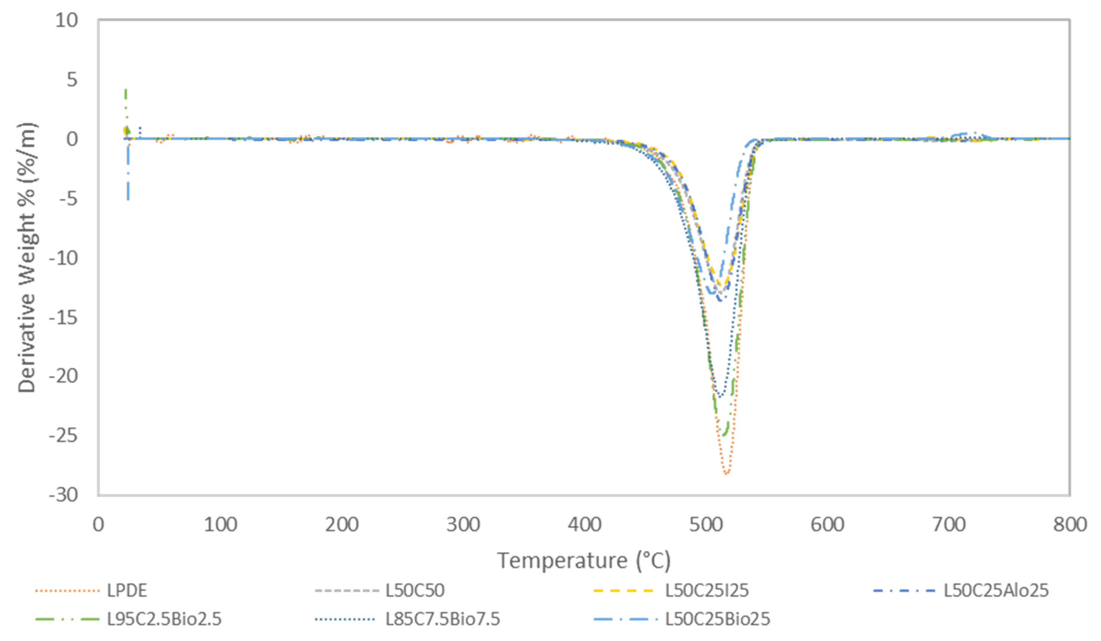
3.2. Thermal Analysis by TGA and DTG
3.3. Tensile Testing
3.4. Density Measurement
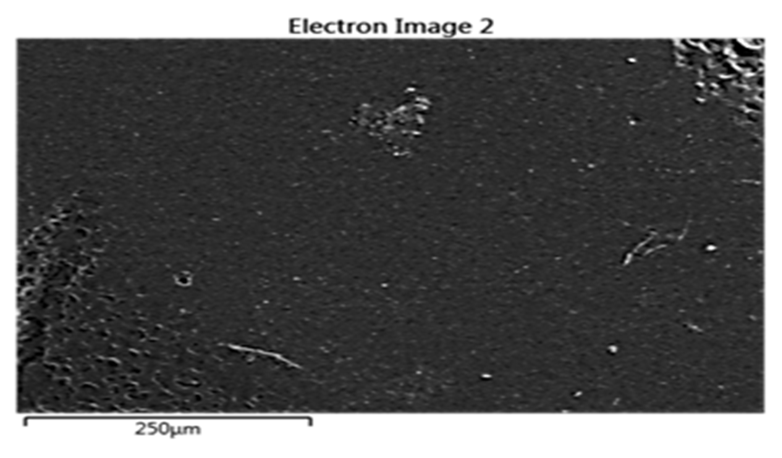
3.5. Scanning Electron Microscopy (SEM) and Energy Dispersive X-ray Spectroscopy (EDS)
Analysis by FTIR Spectroscopy
4. Results and Discussion
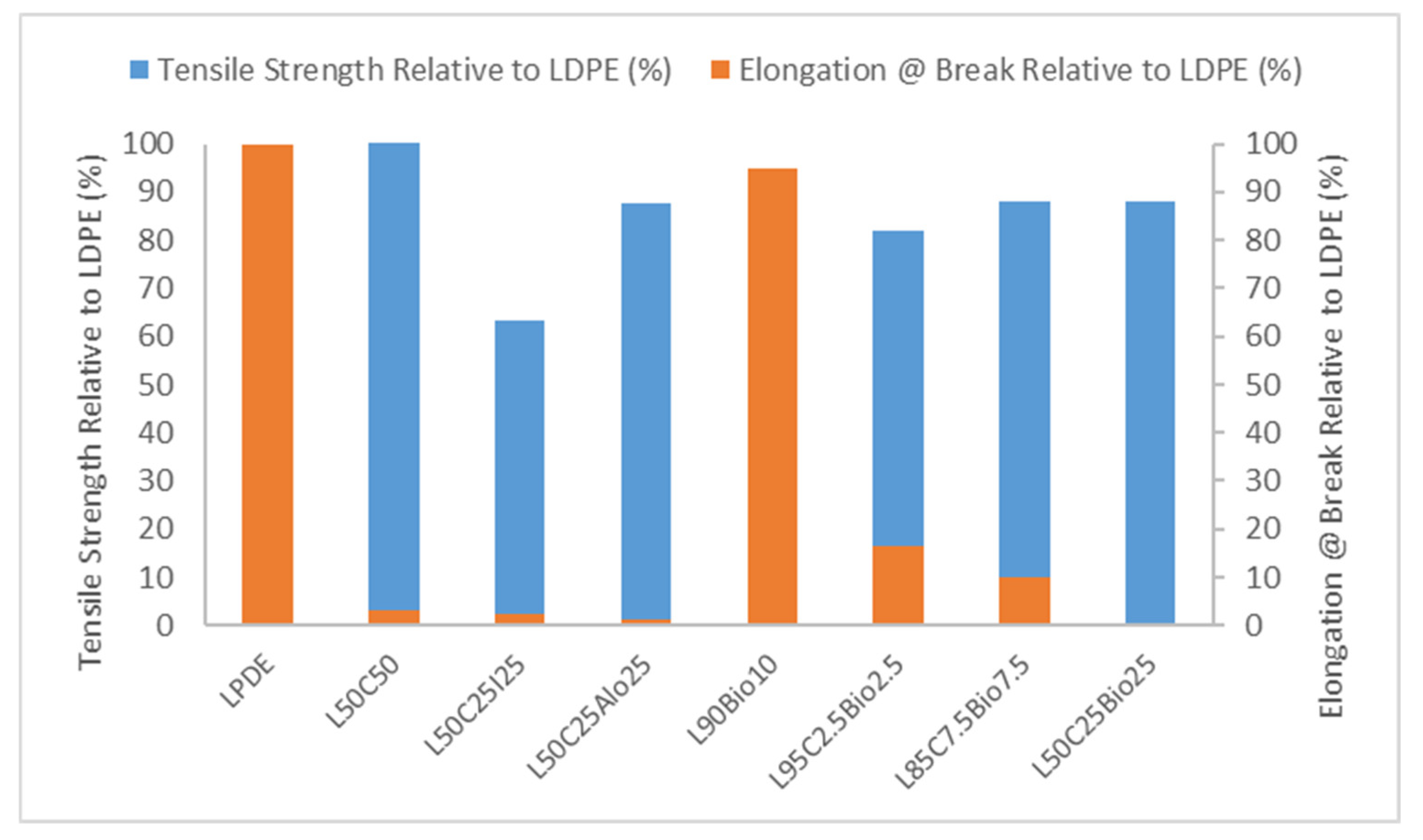
4.1. Tensile Test
4.2. Thermal Analysis by TGA and DTGA
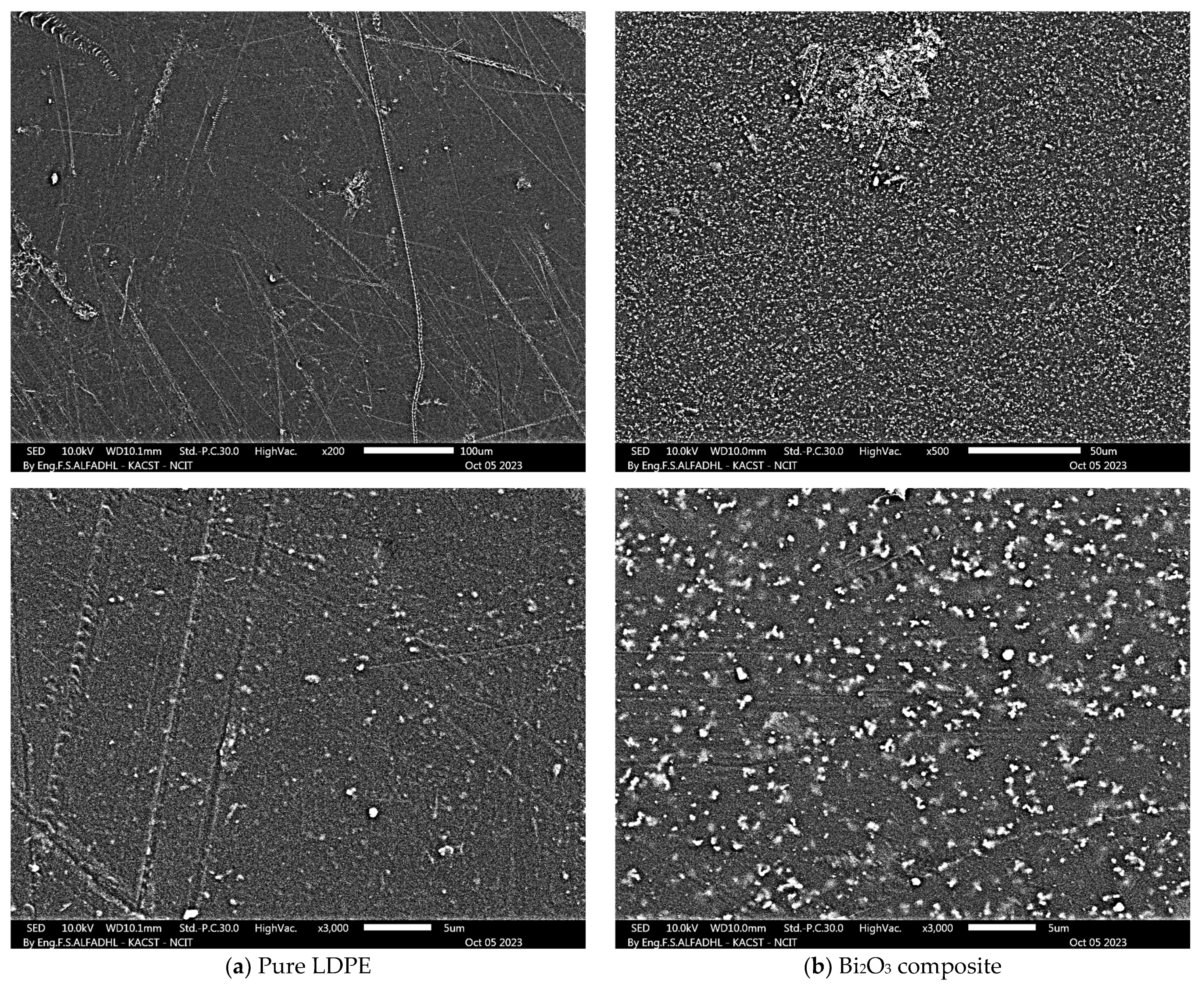
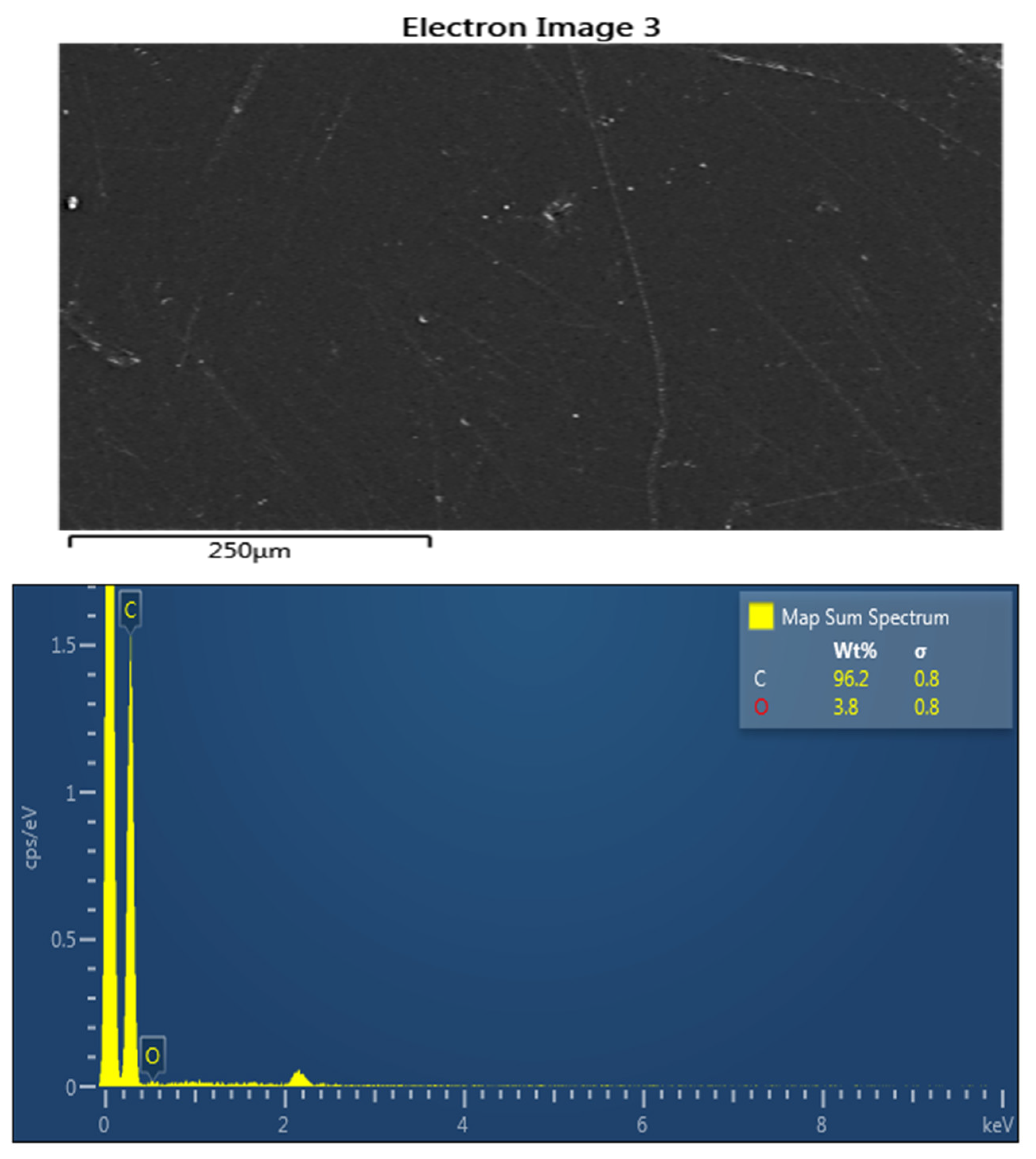
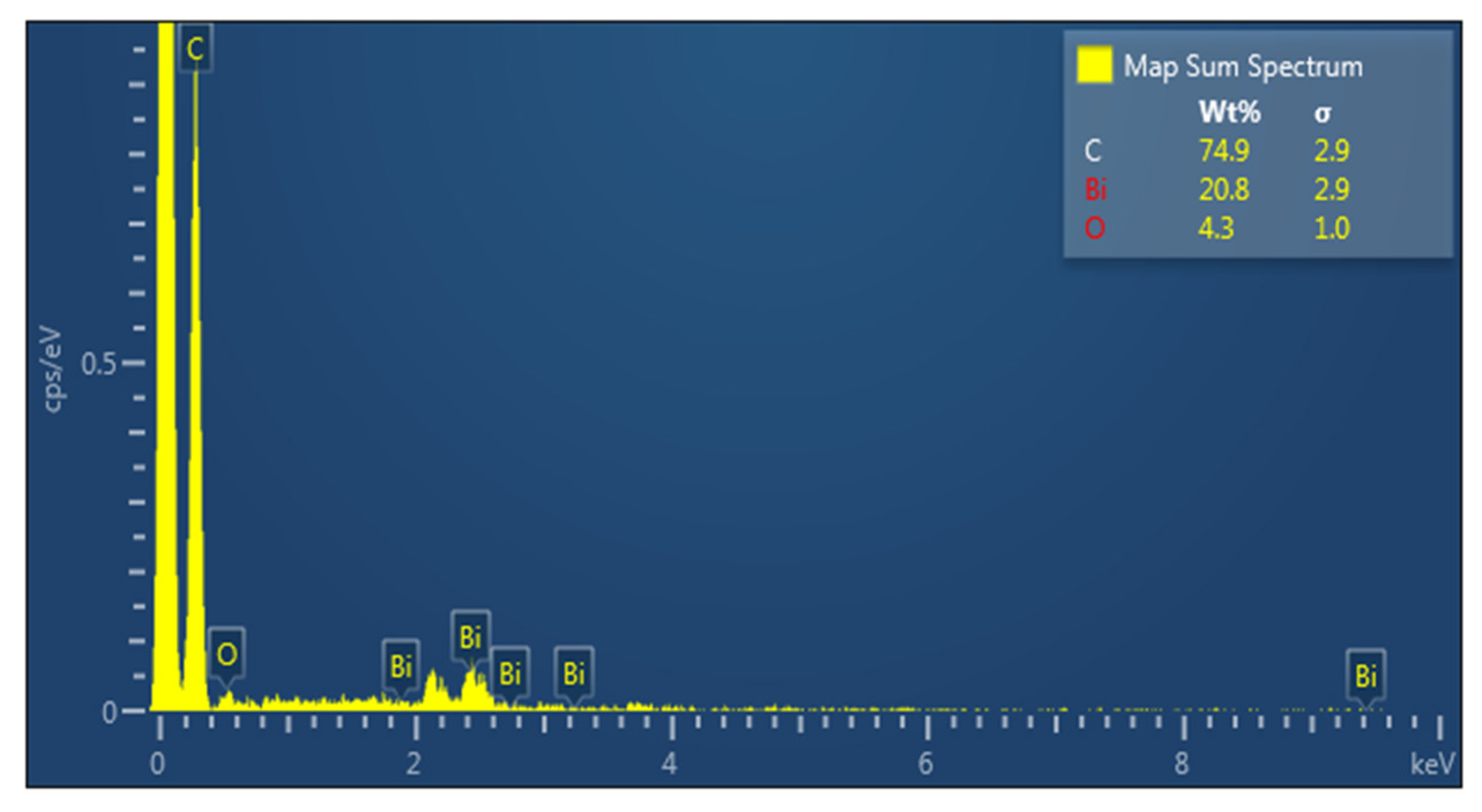
4.3. SEM and EDS Analysis
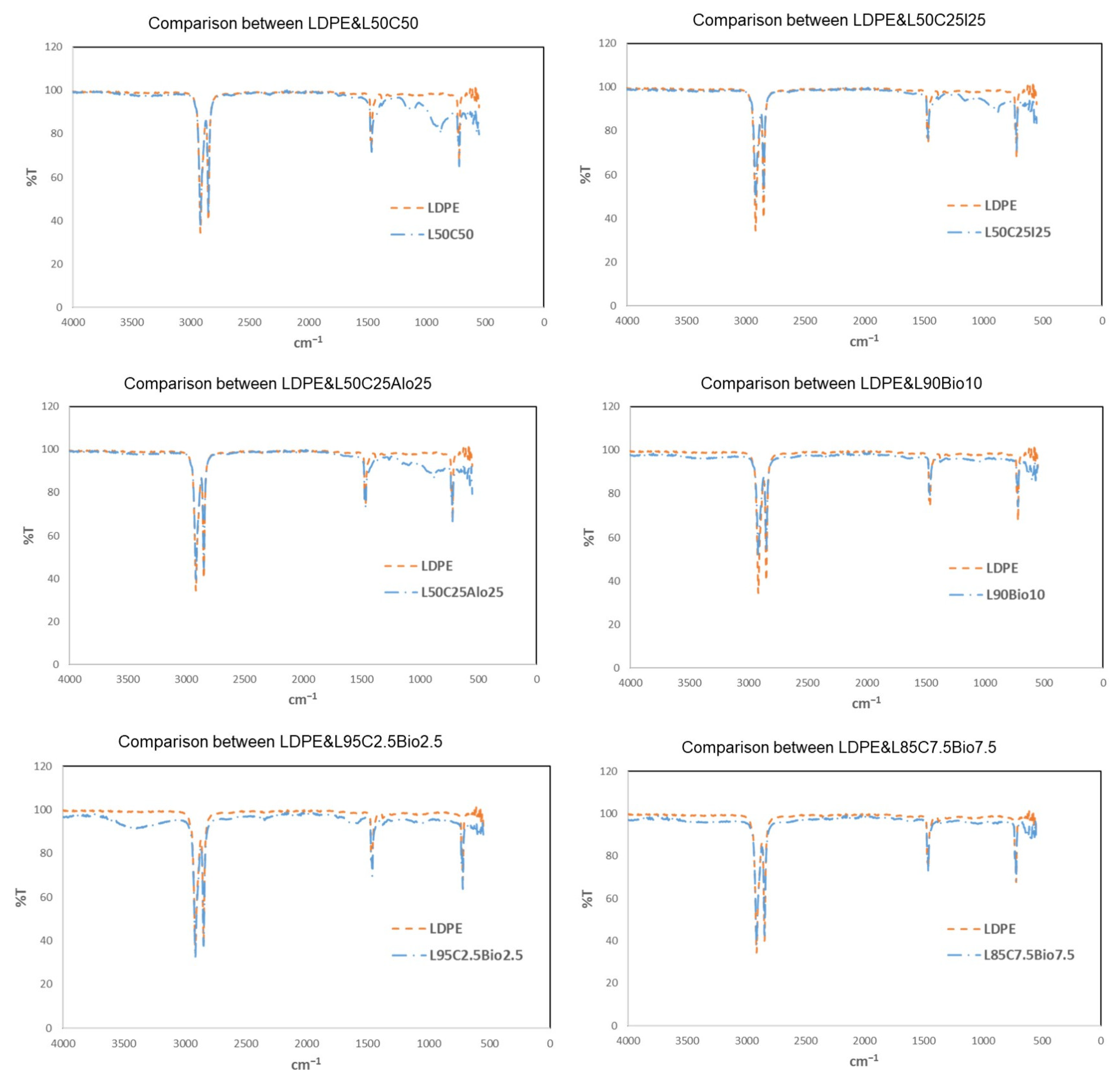
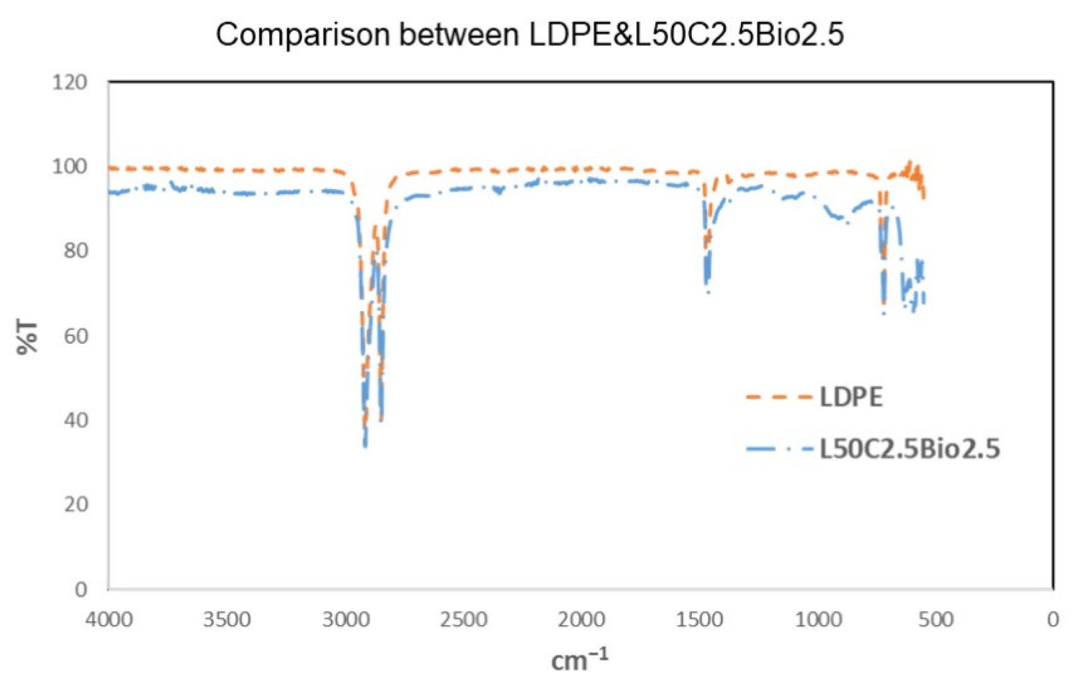
4.4. Fourier Transform Infrared Spectroscopy (FTIR)
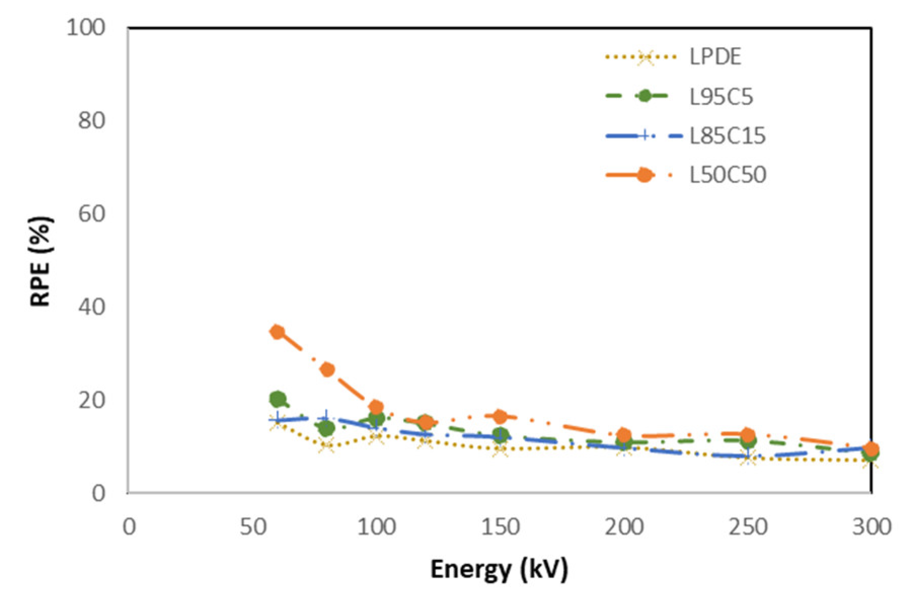
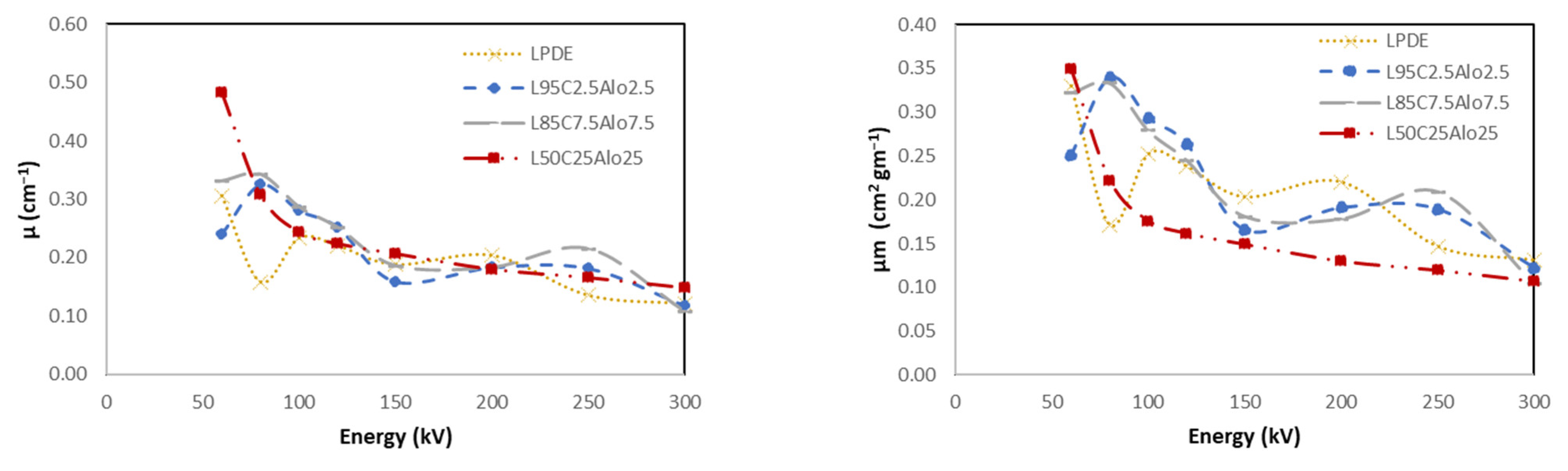
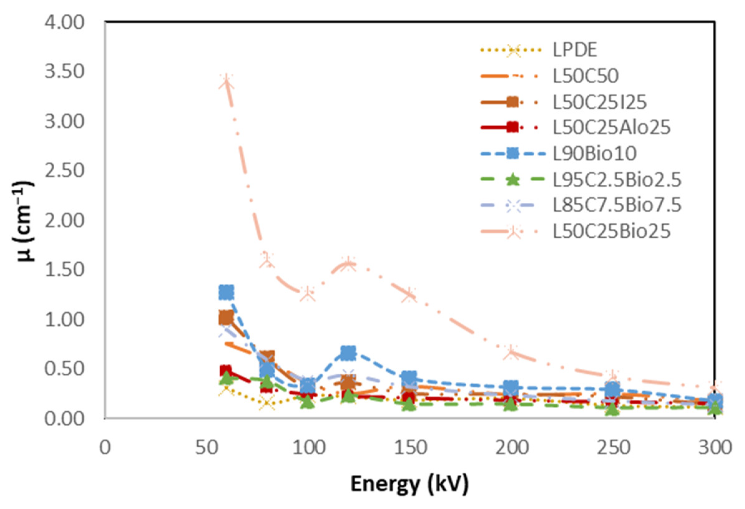
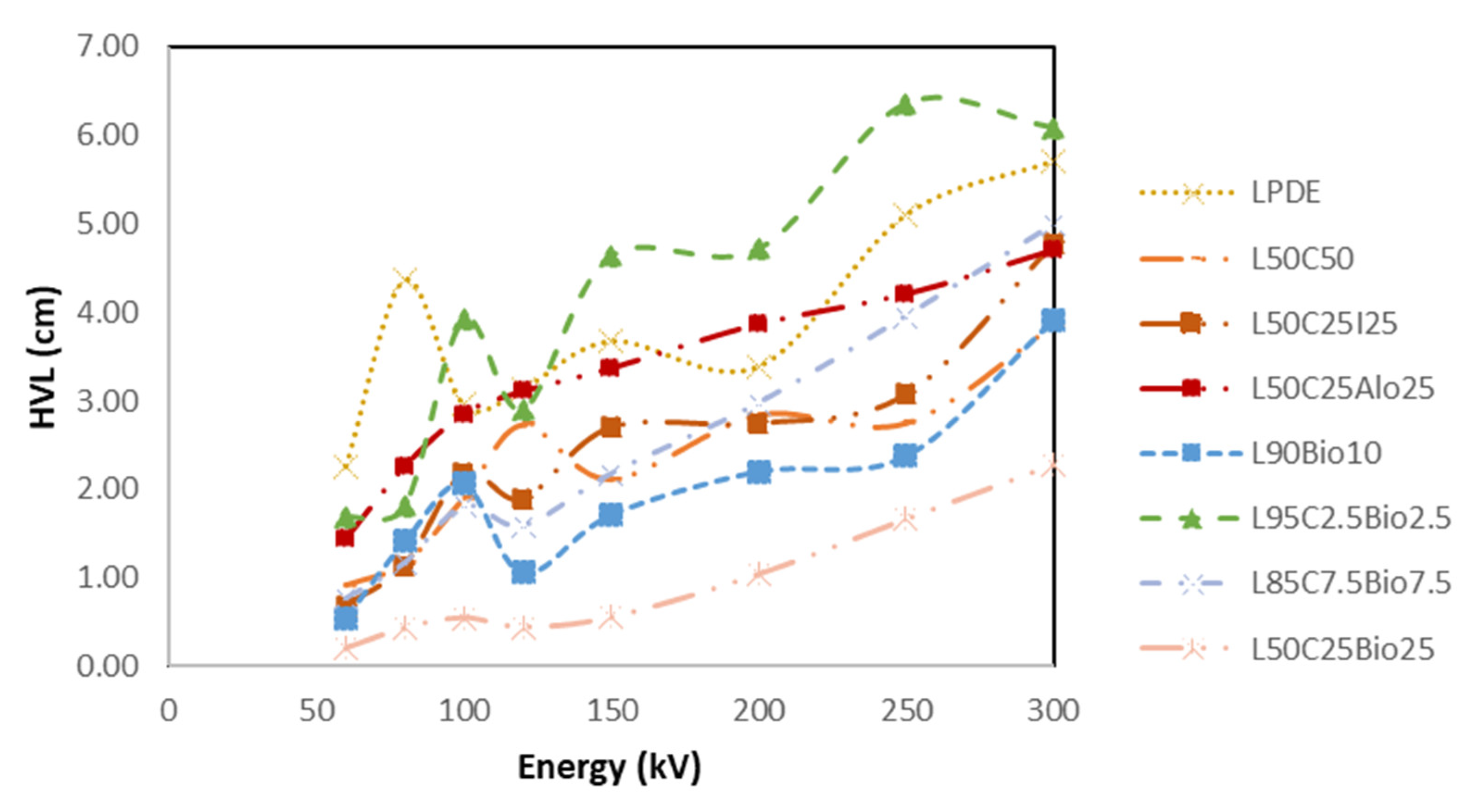
4.5. X-ray Shielding Properties
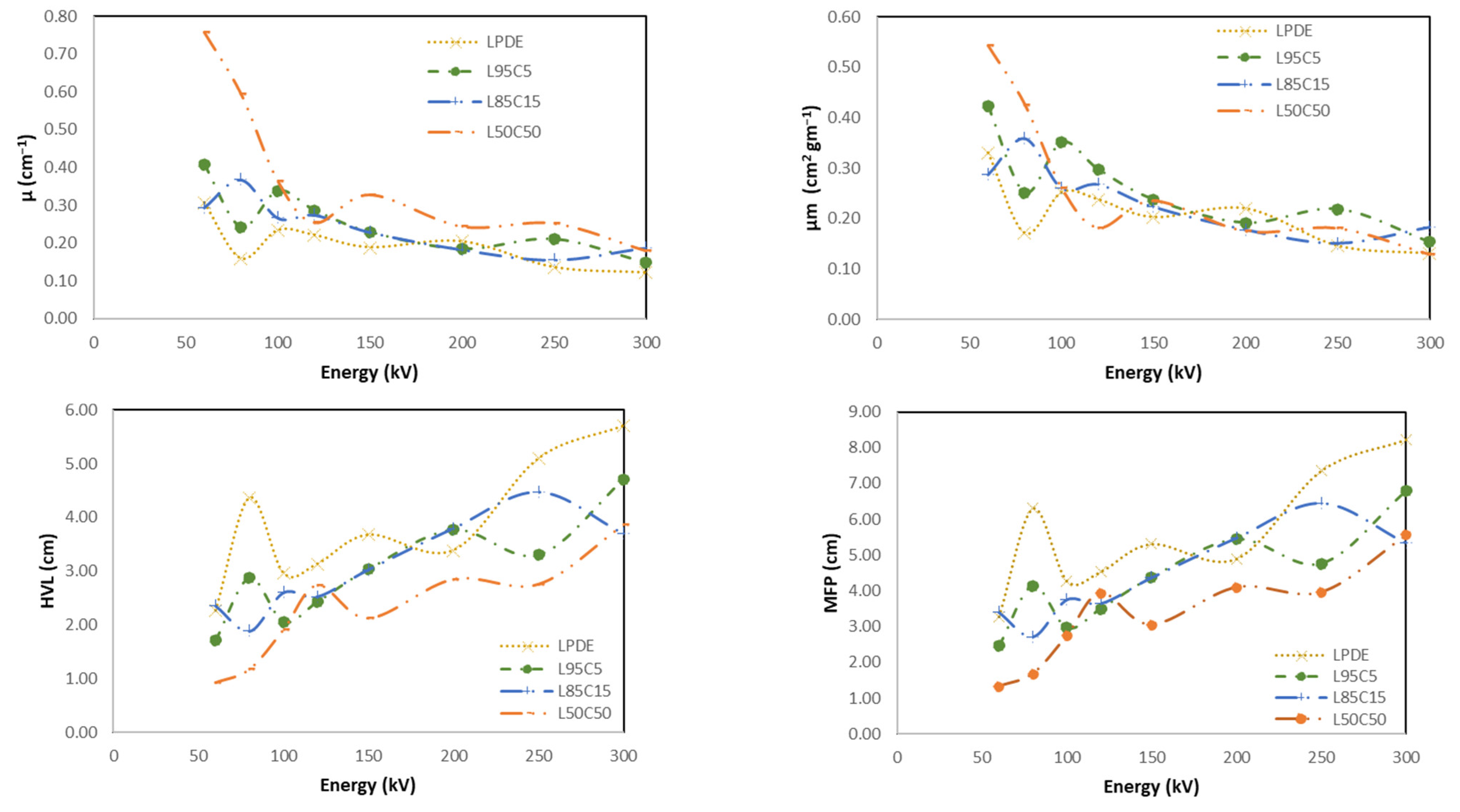
4.5.1. LDPE with Cement
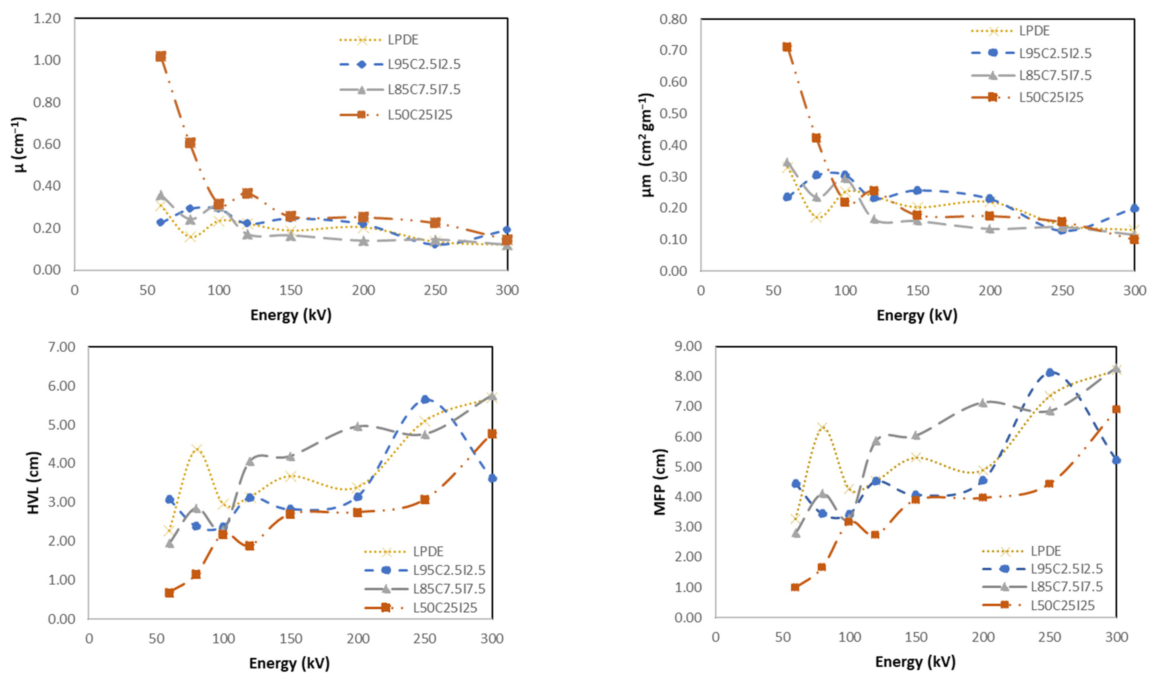
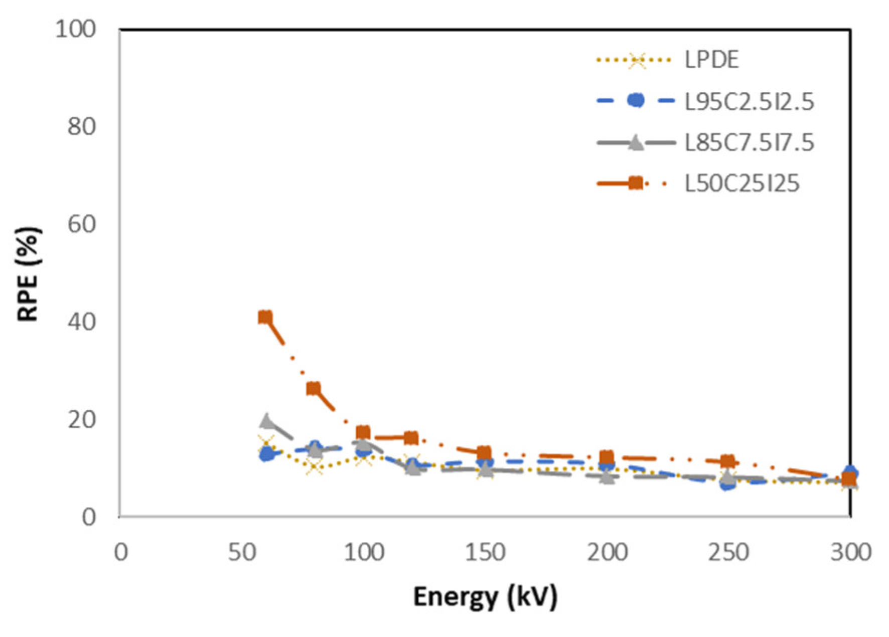
4.5.2. LDPE with Cement and Fe2O3
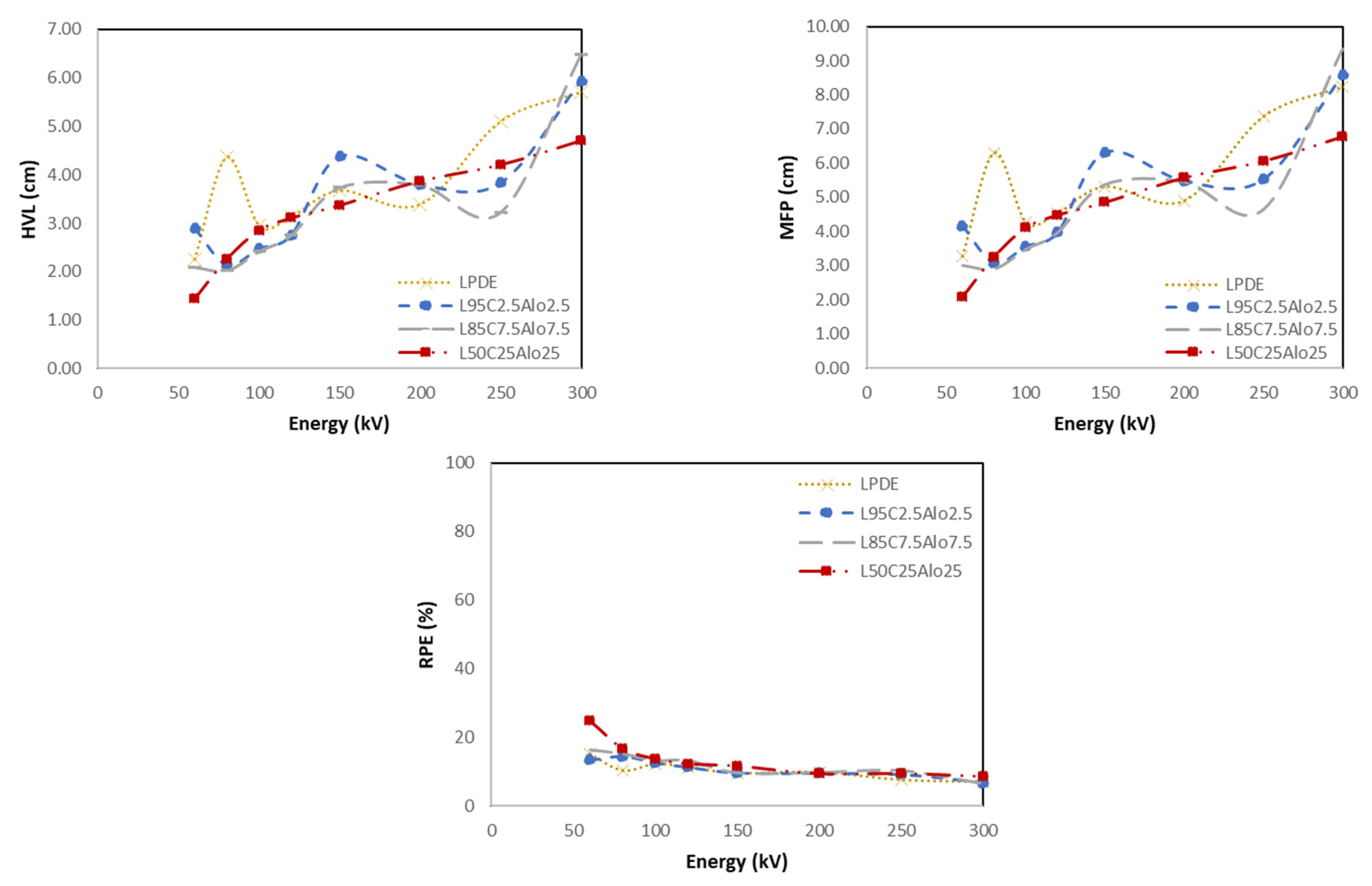
4.5.3. LDPE with Cement and Al2O3
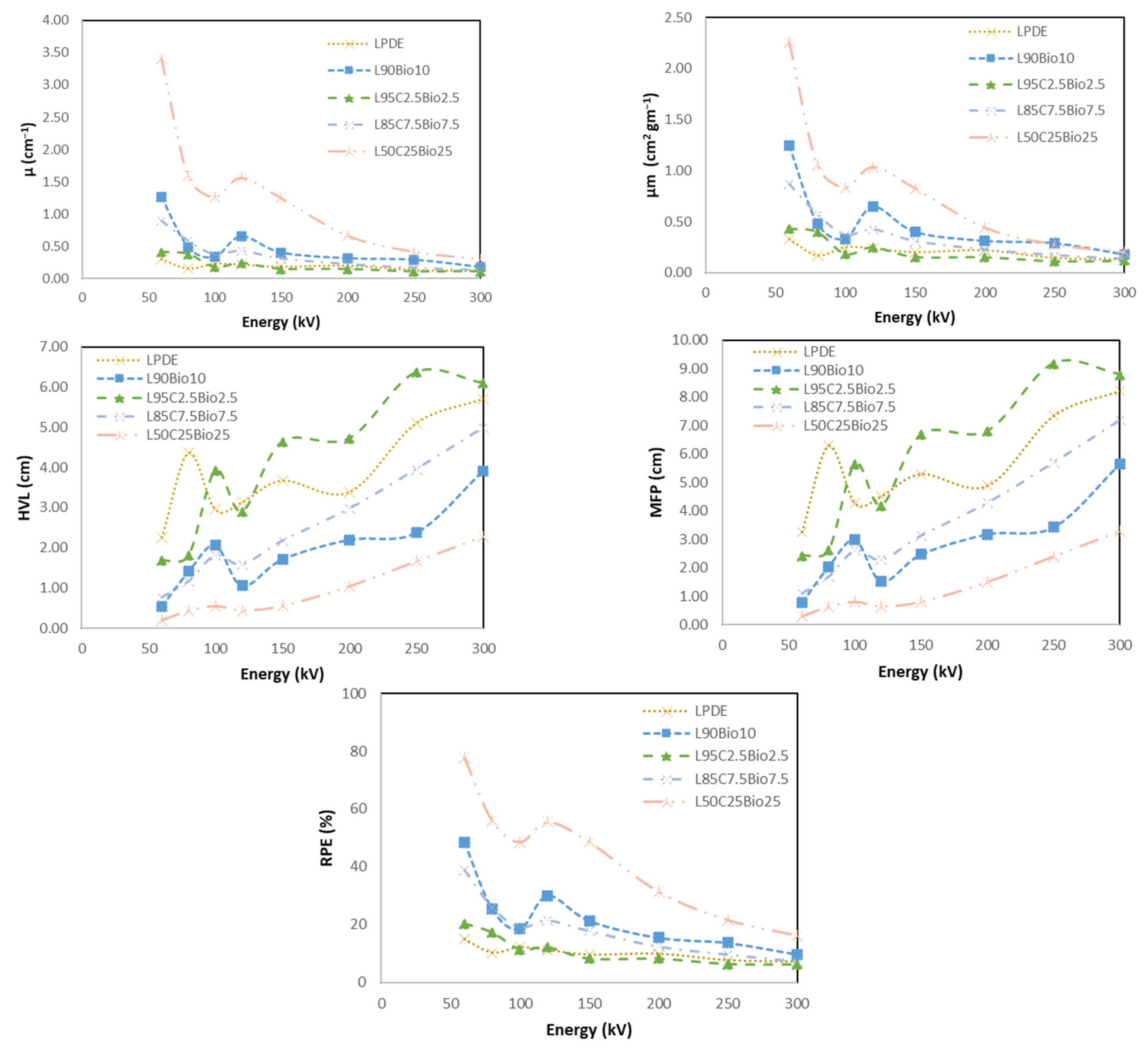
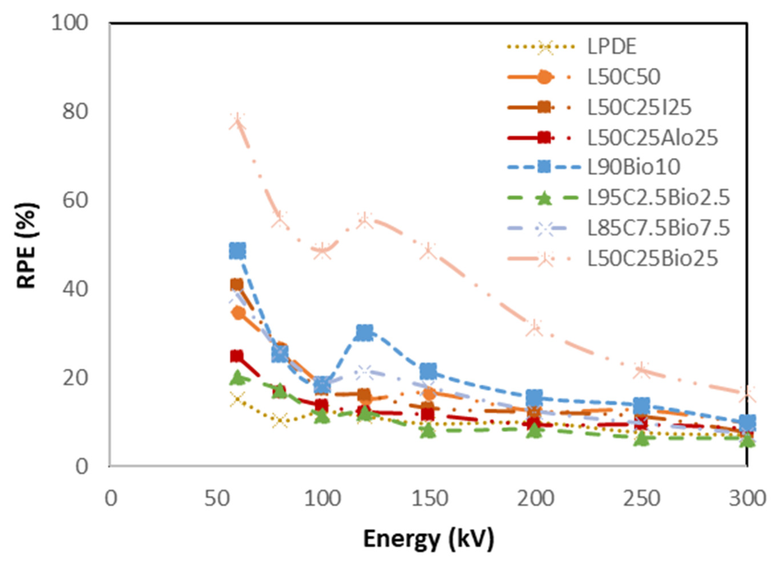
4.5.4. Bismuth Composite
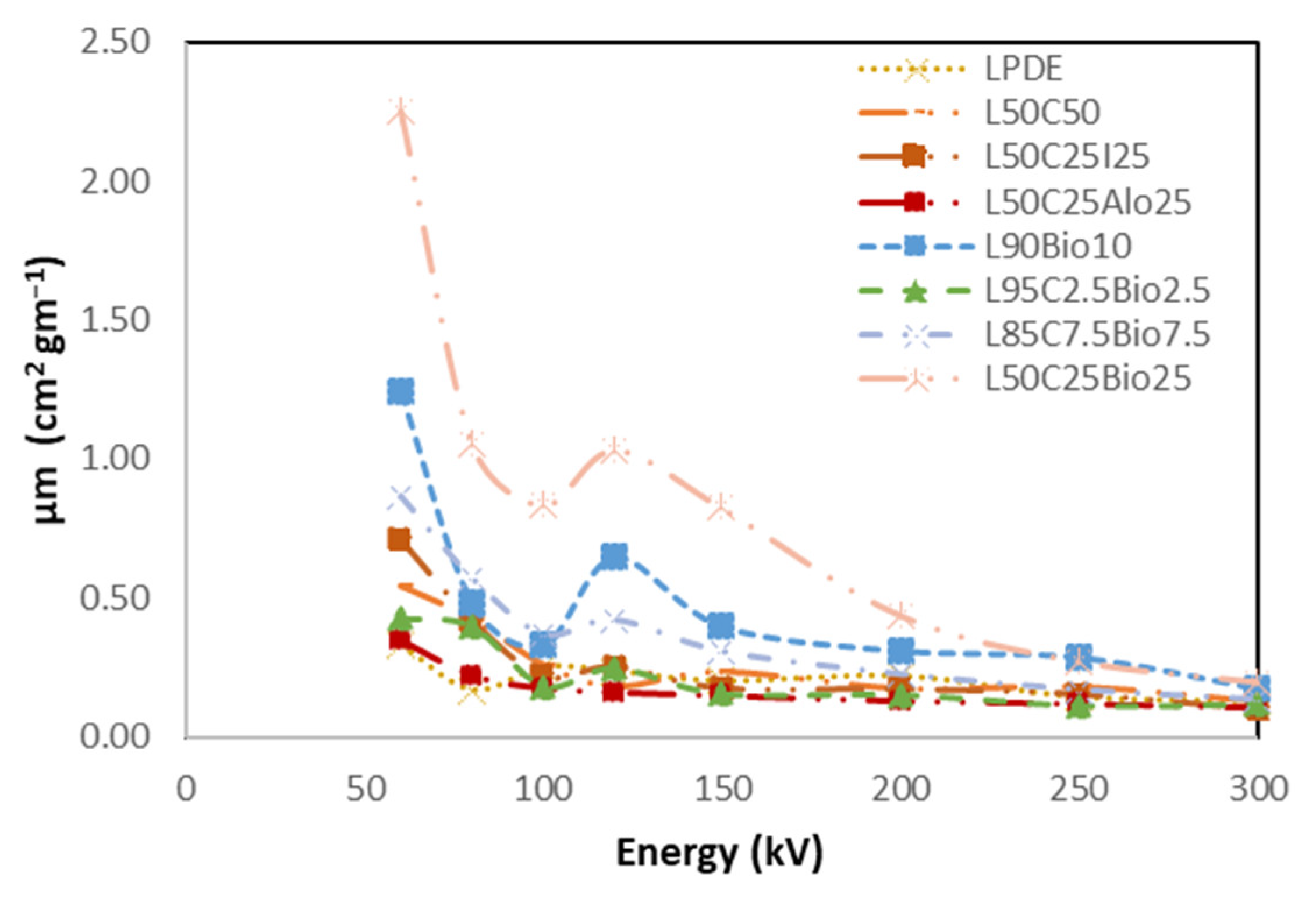
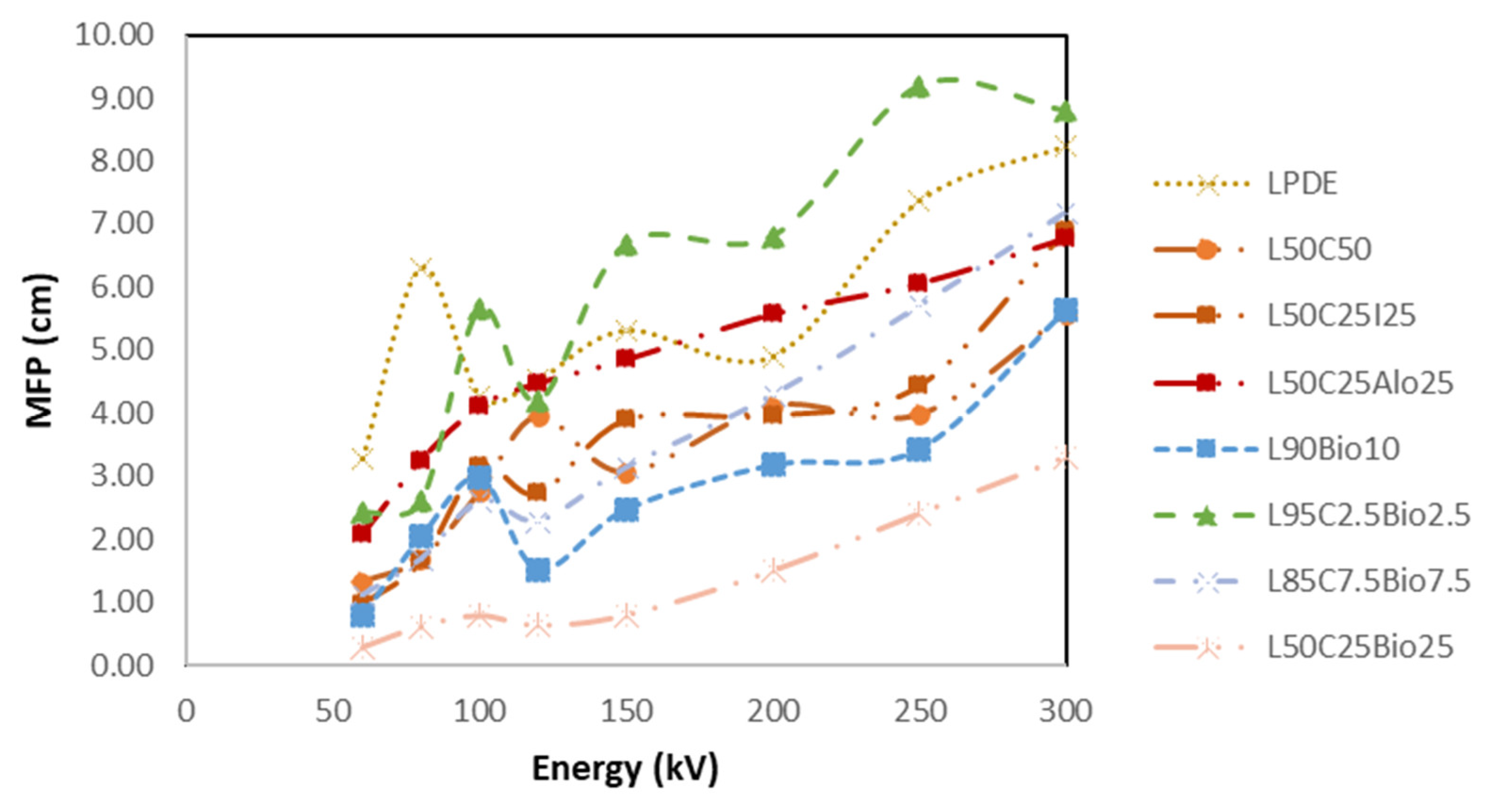
4.5.5. High Shielding Efficiency Composite
5. Conclusions
Author Contributions
Funding
Institutional Review Board Statement
Data Availability Statement
Acknowledgments
Conflicts of Interest
Correction Statement
References
- Olukotun, S.F.; Gbenu, S.T.; Oyedotun, K.O.; Fasakin, O.; Sayyed, M.I.; Akindoyin, G.O.; Shittu, H.O.; Fasasi, M.K.; Khandaker, M.U.; Osman, H.; et al. Fabrication and Characterization of Clay-Polyethylene Composite Opted for Shielding of Ionizing Radiation. Crystals 2021, 11, 1068. [Google Scholar] [CrossRef]
- Li, Z.; Zhou, W.; Zhang, X.; Gao, Y.; Guo, S. High-efficiency, flexibility and lead-free X-ray shielding multilayered polymer composites: Layered structure design and shielding mechanism. Sci. Rep. 2021, 11, 4384. [Google Scholar] [CrossRef] [PubMed]
- Nambiar, S.; Yeow, J.T. Polymer-composite materials for radiation protection. ACS Appl. Mater. Interfaces 2012, 4, 5717–5726. [Google Scholar] [CrossRef] [PubMed]
- Okafor, C.E.; Okonkwo, U.C.; Okokpujie, I.P. Trends in reinforced composite design for ionizing radiation shielding applications: A review. J. Mater. Sci. 2021, 56, 11631–11655. [Google Scholar] [CrossRef]
- Alyousef, H.; Tijani, S.A.; Alsuhybani, M.S.; Alotaibi, W.M.; Alotaibi, B.M.; Alotiby, M.F. The use of low-density polyethylene-molybdenum oxide polymer composites as radiation shielding laminates in dental radiology physical structures. J. Appl. Polym. Sci. 2023, 140, e54701. [Google Scholar] [CrossRef]
- Harish, V.; Nagaiah, N.; Prabhu, T.N.; Varughese, K.T. Preparation and characterization of lead monoxide filled unsaturated polyester based polymer composites for gamma radiation shielding applications. J. Appl. Polym. Sci. 2009, 112, 1503–1508. [Google Scholar] [CrossRef]
- Nambiar, S.; Osei, E.K.; Yeow, T.W. Polymer nanocomposite-based shielding against diagnostic X-rays. J. Appl. Polym. Sci. 2012, 127, 4939–4946. [Google Scholar] [CrossRef]
- Alavian, H.; Tavakoli-Anbaran, H. Comparative study of mass attenuation coefficients for LDPE/metal oxide composites by Monte Carlo simulations. Eur. Phys. J. Plus 2020, 135, 82. [Google Scholar] [CrossRef]
- Almurayshid, M.; Alssalim, Y.; Aksouh, F.; Almsalam, R.; ALQahtani, M.; Sayyed, M.I.; Almasoud, F. Development of New Lead-Free Composite Materials as Potential Radiation Shields. Materials 2021, 14, 4957. [Google Scholar] [CrossRef]
- Alshahri, S.; Alsuhybani, M.; Alosime, E.; Almurayshid, M.; Alrwais, A.; Alotaibi, S. LDPE/Bismuth Oxide Nanocomposite: Preparation, Characterization and Application in X-ray Shielding. Polymers 2021, 13, 3081. [Google Scholar] [CrossRef]
- Sayyed, M.I.; Almurayshid, M.; Almasoud, F.I.; Alyahyawi, A.R.; Yasmin, S.; Elsafi, M. Developed a New Radiation Shielding Absorber Composed of Waste Marble, Polyester, PbCO3, and CdO to Reduce Waste Marble Considering Environmental Safety. Materials 2022, 15, 8371. [Google Scholar] [CrossRef] [PubMed]
- Gbenebor, O.; Osabumwenre, F.; Adeosun, S. Structural, Mechanical and Thermal Properties of Low Density Polyethyline Biomass Composite: Effects of Particle Size. Kufa J. Eng. 2021, 11, 68–84. [Google Scholar] [CrossRef]
- Elmeniawy, M.; Mansour, A.; Hamdy, A.; Saber, D. Mechanical properties and corrosion behavior of sugarcane Bagasse fiber reinforced Low Density Polyethylene composites. Egypt. Int. J. Eng. Sci. Technol. 2021, 36, 63–71. [Google Scholar] [CrossRef]
- Azeko, S.T.; Arthur, E.K.; Minh, D.P.; Lyczko, N.; Nzihou, A.; Soboyejo, W.O. Mechanical and Thermal Properties of Sustainable Composite Building Materials Produced by the Reprocessing of Low-Density Polyethylene, Biochar, Calcium Phosphate, and Phosphogypsum Wastes. J. Mater. Civ. Eng. 2022, 34, 04021457. [Google Scholar] [CrossRef]
- ISO 4037-1:2019; Radiological Protection—X and Gamma Reference Radiation for Calibrating Dosemeters and Doserate Meters and for Determining Their Response as a Function of Photon Energy—Part 1: Radiation Characteristics and Production Methods. ISO: Geneva, Switzerland, 2019; ISC, 17, 17.240.
- Bai, E.-L. Tensile properties of a flexible polymer-cement composite containing portland cement and vae emulsion. Ceramics Silikaty 2019, 64, 92–99. [Google Scholar] [CrossRef]
- Sabri, J.H.; Aalsarraf; Mahdi, K.H. A Comparative Study for Micro and Nano shield of (PbO) composite for gamma Radiation. Energy Procedia 2019, 157, 802–814. [Google Scholar] [CrossRef]
- Gulmine, J.V.; Janissek, P.R.; Heise, H.M.; Akcelrud, L. Polyethylene characterization by FTIR. Polym. Test. 2002, 21, 557–563. [Google Scholar] [CrossRef]
- Abdelsattar, D.E.; El-Demerdash, S.H.; Zaki, E.G.; Dhmees, A.S.; Azab, M.A.; Elsaeed, S.M.; Kandil, U.F.; Naguib, H.M. Effect of Polymer Waste Mix Filler on Polymer Concrete Composites. ACS Omega 2023, 8, 39730–39738. [Google Scholar] [CrossRef] [PubMed]
- Cherkashina, N.I.; Pavlenko, A.V. Synthesis of Polymer Composite Based on Polyimide and Bi12SiO20 Sillenite. Polym.-Plast. Technol. Eng. 2018, 57, 1923–1931. [Google Scholar] [CrossRef]
- Roy, P.; Surekha, P.; Raman, R.; Rajagopal, C. Investigating the role of metal oxidation state on the degradation behaviour of LDPE. Polym. Degrad. Stab. 2009, 94, 1033–1039. [Google Scholar] [CrossRef]
- Gupta, R.; Badel, B.; Gupta, P.; Bucknall, D.G.; Flynn, D.; Pancholi, K. Flexible Low-Density Polyethylene–BaTiO3 Nanoparticle Composites for Monitoring Leakage Current in High-Tension Equipment. ACS Appl. Nano Mater. 2021, 4, 2413–2422. [Google Scholar] [CrossRef]


| No. | Sample Code | LDPE (%) | Cement (%) | Fe2O3 (%) | Al2O3 (%) | Bi2O3 (%) |
|---|---|---|---|---|---|---|
| 1 | LDPE | 100 | X | X | X | X |
| 2 | L95C5 | 95 | 5 | X | X | X |
| 3 | L85C15 | 85 | 15 | X | X | X |
| 4 | L50C50 | 50 | 50 | X | X | X |
| 5 | L95C2.5I2.5 | 95 | 2.5 | 2.5 | X | X |
| 6 | L85C7.5I7.5 | 85 | 7.5 | 7.5 | X | X |
| 7 | L50C25I25 | 50 | 25 | 25 | X | X |
| 8 | L95C2.5Alo2.5 | 95 | 2.5 | X | 2.5 | X |
| 9 | L85C7.5Alo7.5 | 85 | 7.5 | X | 7.5 | X |
| 10 | L50C25Alo25 | 50 | 25 | X | 25 | X |
| 11 | L90Bio10 | 90 | X | X | X | 10 |
| 12 | L95C2.5Bio2.5 | 95 | 2.5 | X | X | 2.5 |
| 13 | L85C7.5Bio7.5 | 85 | 7.5 | X | X | 7.5 |
| 14 | L50C25Bio25 | 50 | 25 | X | X | 25 |
| Shortened Name | Tube Potential (kV) | Effective Energy (keV) | Additional Filtration Thickness | |||
|---|---|---|---|---|---|---|
| mm Pb | mm Sn | mm Cu | mm Al | |||
| N-60 | 60 | 47.9 | - | - | 0.631 | 3.912 |
| N-80 | 80 | 65.2 | - | - | 1.980 | 3.8 |
| N-100 | 100 | 83.3 | - | - | 5.027 | 3.920 |
| N-120 | 120 | 100 | - | 1.013 | 5.027 | 3.950 |
| N-150 | 150 | 118 | - | 2.605 | - | 3.903 |
| N-200 | 200 | 165 | 1.028 | 3.004 | 2.032 | 3.901 |
| N-250 | 250 | 207 | 3.099 | 2.062 | - | 3.925 |
| N-300 | 300 | 248 | 5.152 | 3.016 | - | 3.929 |
| Sample Code | Tensile Strength (MPa) | Elongation at Break (%) | Tensile Strength Relative to LDPE (%) | Elongation at Break Relative to LDPE (%) |
|---|---|---|---|---|
| LPDE | 15.08 ± 0.59 | 350.17 ± 11.59 | 100.00 | 100.00 |
| L50C50 | 16.39 ± 0.34 | 11.34 ± 1.93 | 108.69 | 3.24 |
| L50C25I25 | 9.55 ± 0.18 | 7.88 ± 1.86 | 63.33 | 2.25 |
| L50C25Alo25 | 13.24 ± 0.27 | 4.68 ± 0.44 | 87.80 | 1.34 |
| L90Bio10 | 14.15 ± 0.53 | 332.74 ± 4.94 | 93.83 | 95.02 |
| L95C2.5Bio2.5 | 12.34 ± 0.83 | 57.45 ± 2.15 | 81.83 | 16.41 |
| L85C7.5Bio7.5 | 13.3 ± 0.3 | 35.45 ± 4.29 | 88.20 | 10.12 |
| L50C25Bio25 | 13.3 ± 0.17 | 14.58 ± 1.88 | 88.20 | 4.16 |
| No. | Sample Code | LDPE (%) | Cement (%) | Bi2O3 (%) |
|---|---|---|---|---|
| 1 | L90Bio10 | 90 | X | 10 |
| 2 | L95C2.5Bio2.5 | 95 | 2.5 | 2.5 |
| 3 | L85C7.5Bio7.5 | 85 | 7.5 | 7.5 |
| 4 | L50C25Bio25 | 50 | 25 | 25 |
Disclaimer/Publisher’s Note: The statements, opinions and data contained in all publications are solely those of the individual author(s) and contributor(s) and not of MDPI and/or the editor(s). MDPI and/or the editor(s) disclaim responsibility for any injury to people or property resulting from any ideas, methods, instructions or products referred to in the content. |
© 2024 by the authors. Licensee MDPI, Basel, Switzerland. This article is an open access article distributed under the terms and conditions of the Creative Commons Attribution (CC BY) license (https://creativecommons.org/licenses/by/4.0/).
Share and Cite
Baamer, M.A.; Alshahri, S.; Basfar, A.A.; Alsuhybani, M.; Alrwais, A. Novel Polymer Composites for Lead-Free Shielding Applications. Polymers 2024, 16, 1020. https://doi.org/10.3390/polym16071020
Baamer MA, Alshahri S, Basfar AA, Alsuhybani M, Alrwais A. Novel Polymer Composites for Lead-Free Shielding Applications. Polymers. 2024; 16(7):1020. https://doi.org/10.3390/polym16071020
Chicago/Turabian StyleBaamer, Mazen A., Saad Alshahri, Ahmed A. Basfar, Mohammed Alsuhybani, and Alhanouf Alrwais. 2024. "Novel Polymer Composites for Lead-Free Shielding Applications" Polymers 16, no. 7: 1020. https://doi.org/10.3390/polym16071020
APA StyleBaamer, M. A., Alshahri, S., Basfar, A. A., Alsuhybani, M., & Alrwais, A. (2024). Novel Polymer Composites for Lead-Free Shielding Applications. Polymers, 16(7), 1020. https://doi.org/10.3390/polym16071020