Article

Design and Test of Intelligent Farm Machinery Operation Control Platform for Unmanned Farms

1
College of Engineering/Guangdong Laboratory for Lingnan Modern Agriculture, South China Agricultural University, Guangzhou 510642, China
2
Anhui Zhongke Intelligent Sense Industrial Technology Research Institute, Anhui 241002, China
*
Author to whom correspondence should be addressed.
Agronomy 2024, 14(4), 804; https://doi.org/10.3390/agronomy14040804
Submission received: 24 February 2024 / Revised: 28 March 2024 / Accepted: 9 April 2024 / Published: 12 April 2024
(This article belongs to the Section Precision and Digital Agriculture)

Abstract

:
The unmanned farm control platform is of great significance in promoting the supervision of farm production with less manpower or autonomous operation of farm machinery and the construction of farm informatization. Addressing the existing control platform for farm location information acquisition is time-consuming, labor-intensive, and lacks the whole process control of multiple types of farm machinery. In this paper, we propose an Internet of Things (IoT) control scheme for intelligent farm machinery operation of unmanned farms and design the access standards for multiple types of farm machinery, as well as realize the remote control of intelligent farm machinery operation by constructing a remote control model. A high-precision map construction method is designed to improve the DeepLabV3+ algorithm to identify fields and roads. The control models of path planning, remote task, remote control, and safety system are built to achieve the remote control of intelligent agricultural machinery operation. The proposed technology is implemented in the platform integration and application tests are carried out. The error of the constructed high-precision map is less than 3 cm, the completeness rate of the automatic boundary extraction rate is 96.71%, and the correctness rate is 95.63%, which can be used to obtain the boundary instead of manual labeling or on-site point picking. The use of the platform for the simultaneous control of three farm machinery operations reduces the number of people in operation and production and reduces the professional requirements of the personnel, which will promote the management of the entire farm by one person or even by no one in the future.

1. Introduction

Industrialization and urbanization continue to accelerate. According to data from the Seventh National Population Census, in 2020, the proportion of the elderly population aged 60 and over, as well as 65 and over, in China’s rural areas relative to the total rural population was 23.81% and 17.72%, respectively. China’s urbanization rate of the resident population has risen from 17.92% in 1978 to 64.72% in 2021. Consequently, the proportion of individuals employed in primary industries has declined from 70.53% to 22.87%. The decline in the rural labor force and the aging of the workforce have raised concerns regarding “who will farm and how to farm” [1]. The development of smart agriculture provides technical support to alleviate labor shortages [2,3,4,5,6,7]. As a significant facet of smart agriculture, unmanned farms achieve the integration of information perception, quantitative decision-making, intelligent control, precise inputs, and personalized services throughout the agricultural production process [8,9,10,11,12,13,14,15]. The remote control platform of unmanned farms realizes remote transmission, with cloud management and intelligent analysis of online monitoring data, providing crucial data support for fault diagnosis and real-time early warning, significantly improving the management efficiency of agricultural machinery while reducing production costs [16].
Presently, several research efforts and practical applications are dedicated to developing an unmanned farm control platform for comprehensive monitoring and intelligent scheduling of farm production activities. Kaloxylos et al. [17] proposed an architecture comprising a cloud management system and a local management system. They found that 88% of respondents believed such a system could reduce their operational costs, and 90% found it easy to use. Fountas et al. [18] examined farm management information systems (FMIS) from academic and business perspectives, identifying common issues and solutions. Feng Minkang et al. [19] established an unmanned farm control platform to facilitate task allocation and remote supervision of farm machinery operations. Lu Bang et al. [20] designed a platform for online path planning of high-precision maps, remote control of farm machinery, and operation monitoring for tractor rapeseed sowing, achieving a maximum map plane accuracy error of 3.23 cm. Chen Huailin et al. [21] developed an FMIS interaction strategy by considering user, operational, environmental, and equipment contexts, and aligning them with FMIS tasks. Li Han et al. [22] created a multi-machine navigation service platform through WEBGIS, offering an efficient solution for multi-machine operation path planning and task allocation. Liu Zhenyu et al. [23] devised a platform for scheduling and operating agricultural machines, enabling intelligent scheduling according to supply and demand, as well as monitoring the entire process. Wang Chunshan et al. [24] proposed a layered management platform architecture to enhance system scalability. Lv Yacong [25] crafted a highly cohesive and low-coupling intelligent agricultural vehicle monitoring system using microservices architecture to improve scalability and responsiveness.
The aforementioned technology research primarily focuses on field data collection and collation, as well as agricultural machinery geographic location and operation data collection and collation, and furthermore agricultural machinery scheduling and information sharing. However, manual collection of field and road boundary information is both time-consuming and costly. Moreover, while certain aspects of operations such as ploughing, planting, management, and harvesting are often controlled, there is limited research on unmanned farm control platforms encompassing the entire process of intelligent farm machinery operation. Given the aforementioned status quo, the objectives of this study are as follows: (1) To establish an Internet of Things (IoT) platform for the operation and control of various types of intelligent farm machinery; (2) to employ machine learning algorithms for comprehensive identification of farm roads and fields and to construct high-precision maps; and (3) to facilitate real-time data interactions with farm machinery to achieve remote supervision of the operational processes. The research contents and innovations of this paper encompass the following: (1) Design of the control platform architecture for intelligent farm machinery operation; (2) establishment of an efficient, high-precision, and diversified information fusion digital map of the farm; and (3) development of a remote control methodology for intelligent farm machinery throughout the entire process of ploughing, planting, management, and harvesting.

2. Materials and Methods

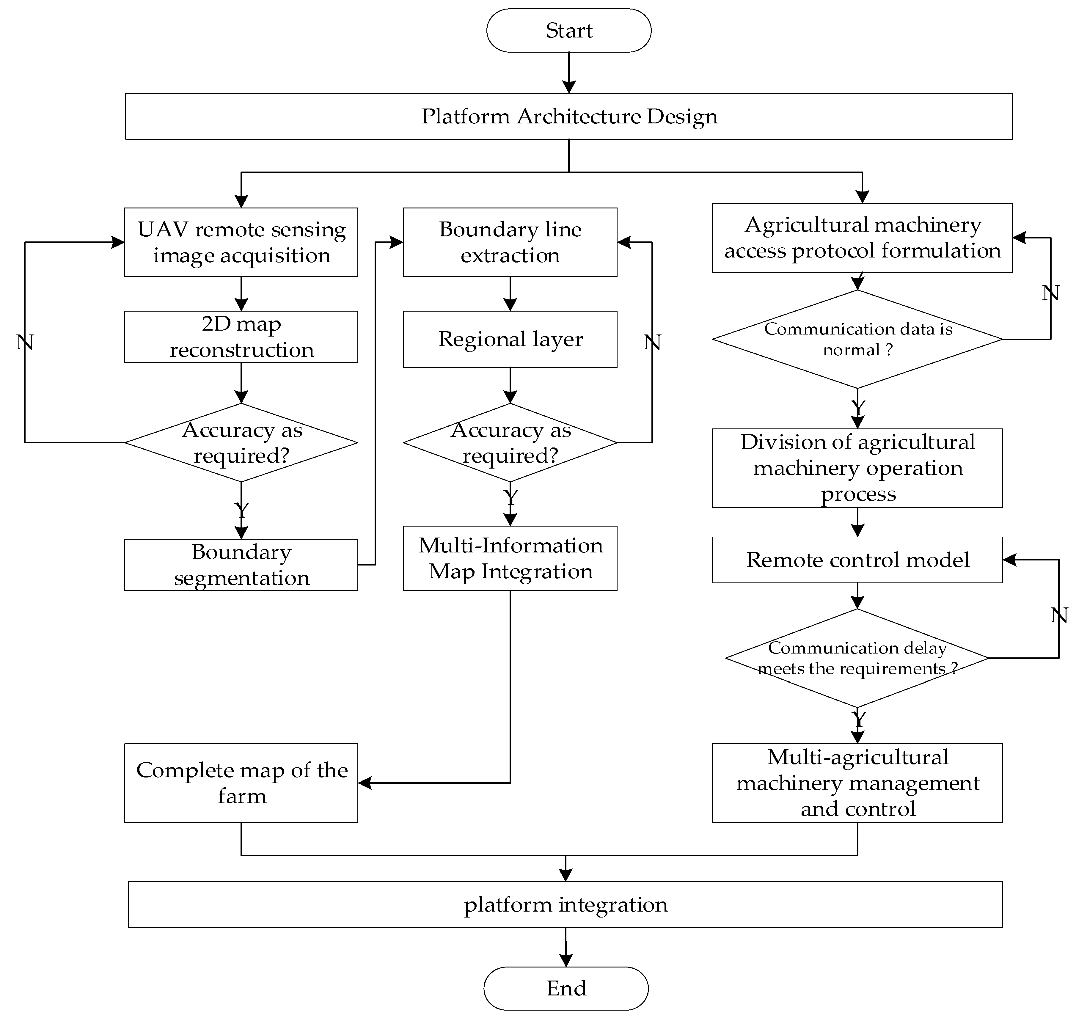
2.1. Technical Routes

The research technology pathway outlined in Figure 1 encompasses platform design, high-precision map construction, and remote control of intelligent farm machinery operations. By acquiring farm images, the construction of a high-precision map for the farm entails identifying farmland and roads to derive layers and integrate diverse information into the map. This completed high-precision farm map serves the purpose of information collection and visualization concerning farm machinery operations. Moreover, access standards for various types of farm machinery are established to enable remote control of intelligent farm machinery operations through the development of a remote control model.

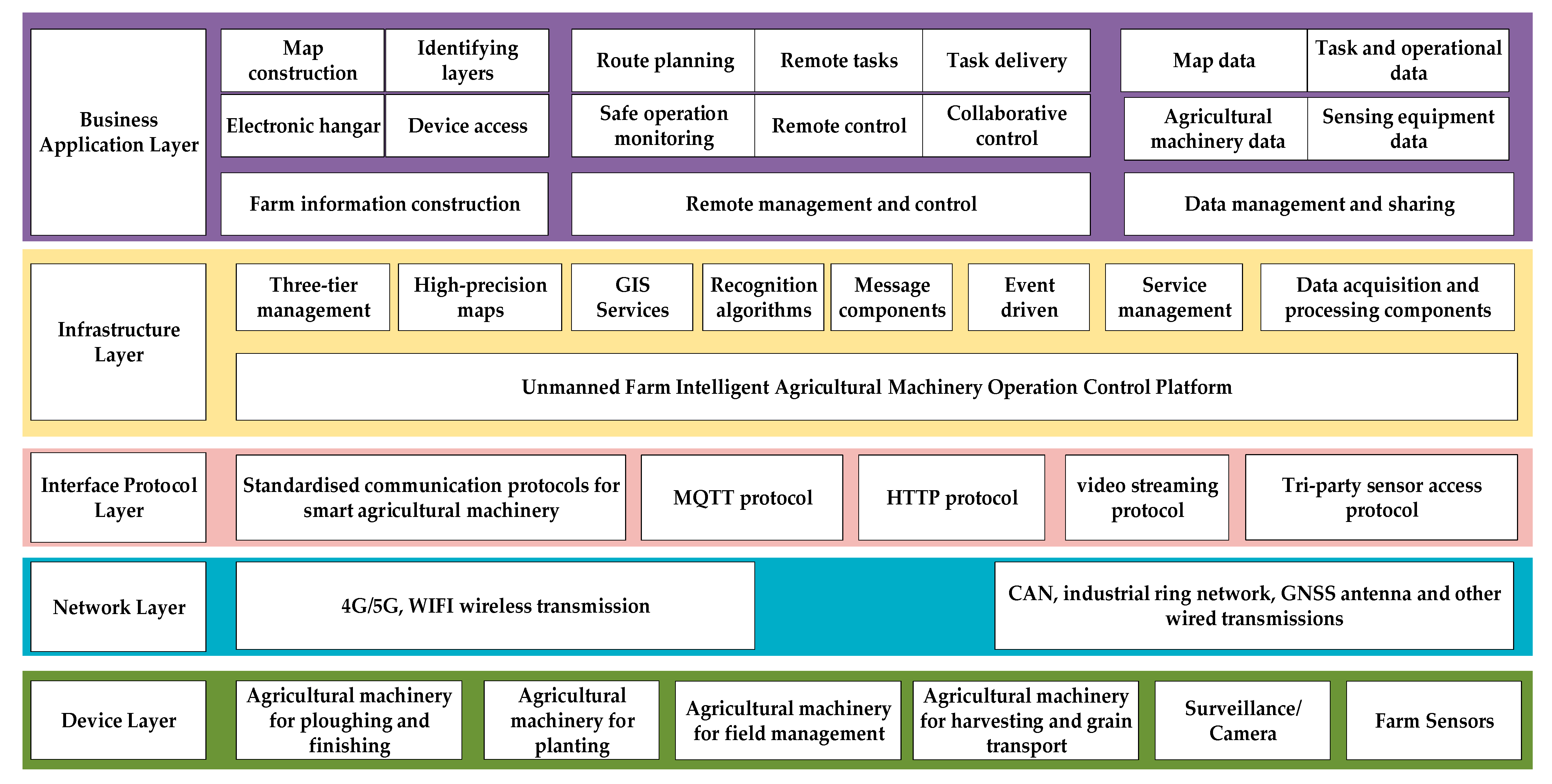
2.2. Platform Infrastructure

In this paper, the design of the platform architecture begins with a focus on farm machinery operation services. Based on the specific requirements of farm operations and the intelligent control processes involved, the overall architecture of the platform is delineated, as depicted in Figure 2. This architecture comprises the device layer, the network layer, the interface protocol layer, the basic platform layer, and the business application layer.
The equipment layer comprises intelligent farm machinery or equipment, serving as the primary component throughout the entire agricultural production process in unmanned farms. It constitutes the central element in production operations within unmanned farms, encompassing monitoring and sensors as key components.
The network layer serves as the conduit for data transmission between intelligent farm machinery, devices, and platforms, facilitating communication of data between the equipment layer and higher-level data.
The interface protocol layer facilitates the structured storage of various types of intelligent farm machinery and orchestrates the collection, control, and attribute binding of data through the specification of integration protocols for intelligent farm machinery, devices, and communication data. The use of the MQTT (Message Queuing Telemetry Transport) protocol enables communication between integrated display and control terminals and the platform. This protocol is particularly suited for scenarios with constrained hardware storage or limited network bandwidth, offering features such as long connections and real-time capabilities, making it highly suitable for real-time control environments and actuators [26,27].
The basic platform layer constitutes an unmanned farm intelligent agricultural machinery operation control platform, which is structurally designed with considerations for both management and technology aspects. The management aspect involves the design of a “three-level” management mode for hierarchically overseeing multiple farms. On the other hand, the technical design encompasses network architecture, map construction, remote control, data collection and processing, and service management. The platform adopts the B/S network architecture (Browser/Server) to integrate high-precision maps, GIS (Geographic Information System) services, and recognition algorithms for farm map construction. Remote control functionality is achieved through the implementation of message components and event drivers for diverse command control and module processing. Furthermore, the platform is configured with multiple services and facilitates their discovery.
The business application layer involves the realization of business processes and core functions as per practical requirements. These functions encompass farm information construction, remote control, data management, and sharing. The focal point of the unmanned farm intelligent machinery operation control platform is the intelligent farm machinery. Map construction facilitates accurate visualization of areas and aids in location determination for the transfer and operation of farm machinery in the field. The electronic hangar serves as a digital repository for intelligent farm machinery. Equipment management provides requisite data support to ascertain the operational readiness of farm machinery and the suitability of prevailing conditions. Remote control functionality enables the remote execution of tasks, task assignment, safety, and operational monitoring, as well as collaborative management and control. Data management and sharing entail the classification and management of various farm data segments and their sharing over the Internet.

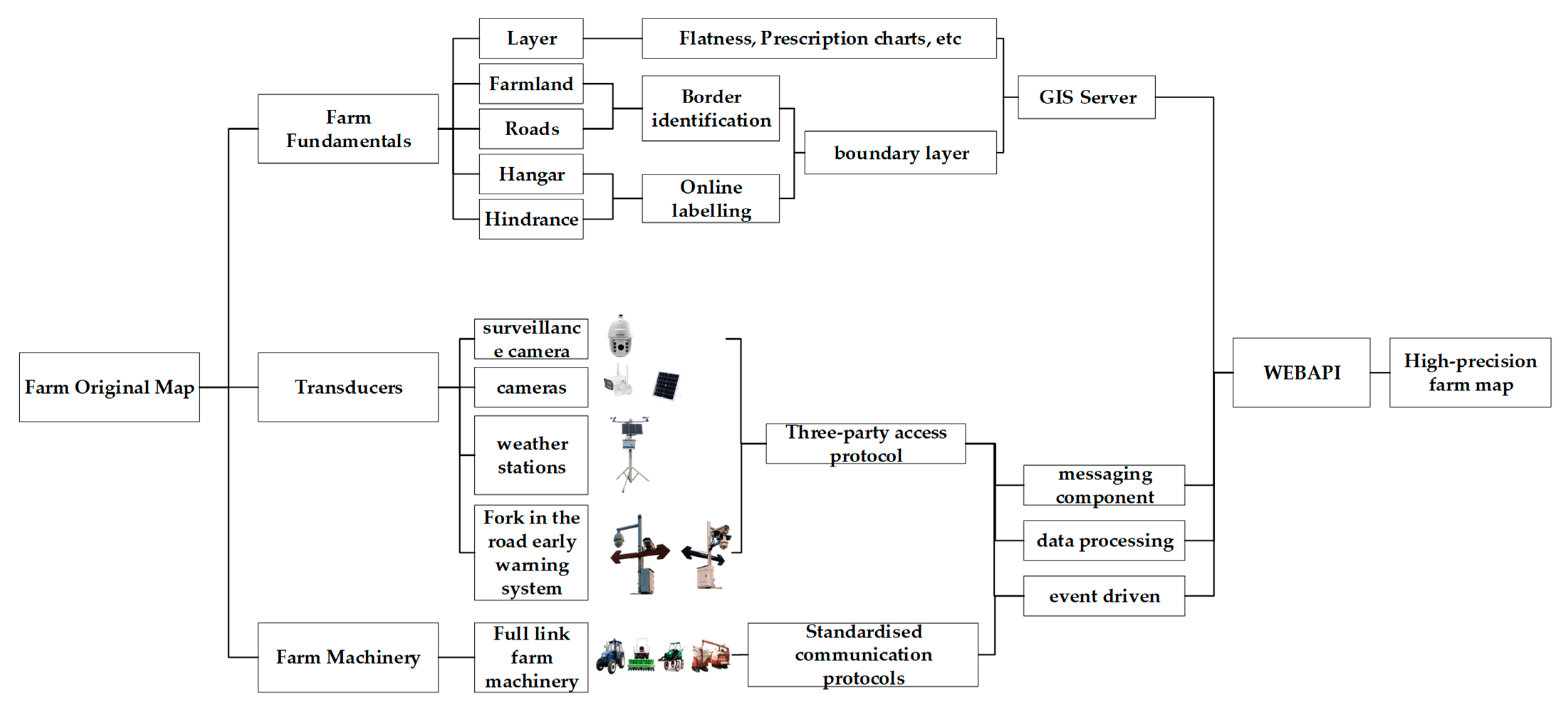
2.3. High-Precision Map Construction

Farmland maps utilized by drones require enhanced positioning accuracy and reliability [28,29,30]. By employing high-precision maps, key farm information can be identified or annotated, thereby facilitating efficient and precise marking and data collection for various elements such as farm fields, roads, equipment positioning, obstacles, hangar areas, and waypoints for intelligent farm machinery path planning.

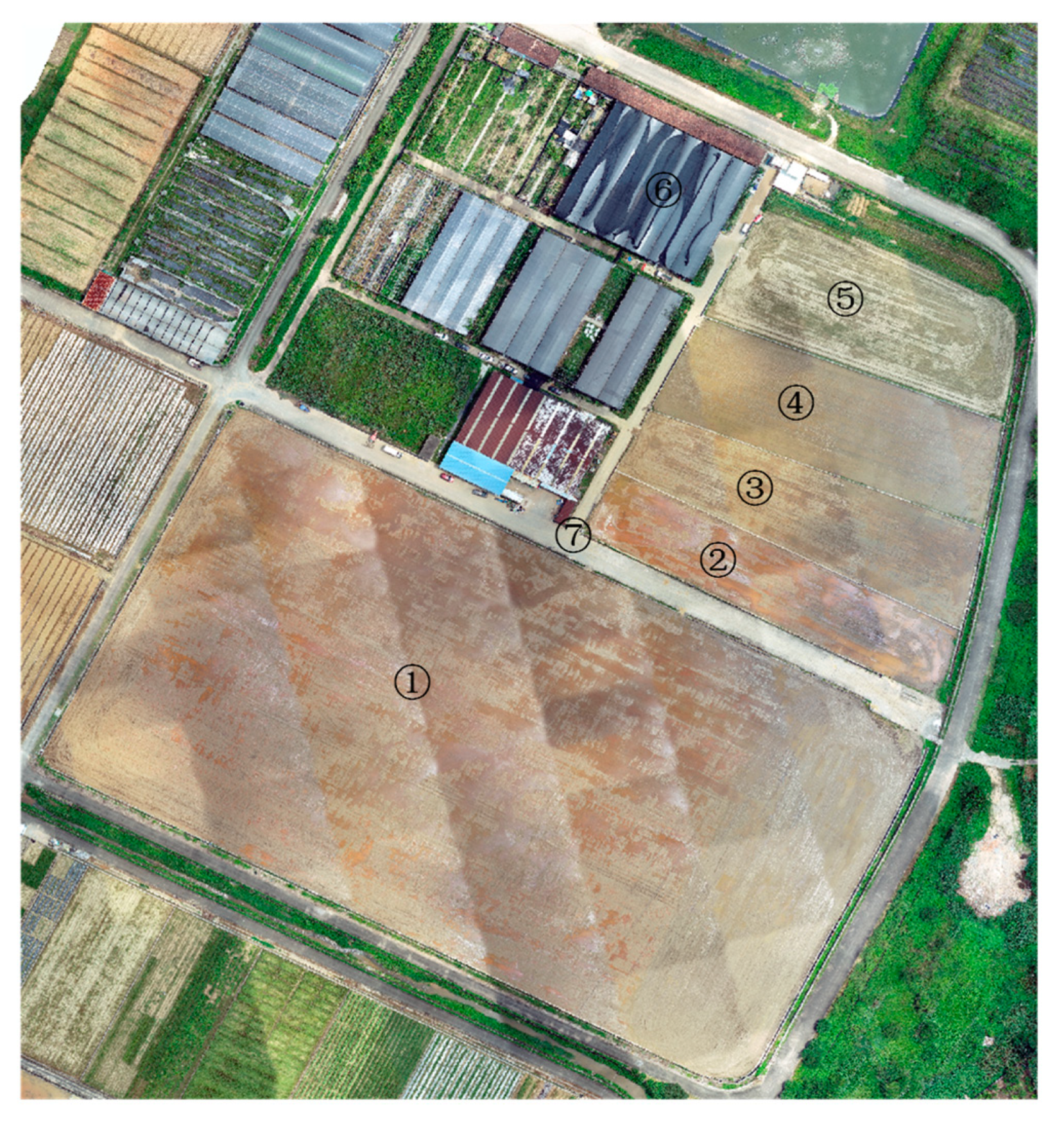
2.3.1. Farm Image Acquisition and Original Map Construction

A small multi-rotor high-precision aerial survey UAV is employed for farm image collection, involving the following steps: (1) Selection of the farm area and formulation of the flight route; (2) configuration of flight parameters, including flight altitude, sampling distance, flight speed, heading overlap rate, bypass overlap rate, and the time interval for capturing images, aimed at enhancing image quality and model training efficacy; (3) utilization of collected image data for 2D reconstruction; (4) verification of reconstruction results and rectification of any anomalous outcomes or artifacts; and (5) acquisition of reconstructed RGB and TIF map images.
Given the typically large size of the output map image files, which can lead to slow upload speeds and laggy zoom-in and zoom-out displays, a map image raster pyramid is constructed to enhance user experience. This construction involves loading lower-resolution layer data from the pyramid when zooming out and higher-resolution layer data when zooming in, ensuring uninterrupted performance regardless of the displayed area size and thereby accelerating map display speed. ArcGIS Server is utilized to deploy online map service technology, generating image link addresses for cloud-based retrieval, eliminating the need for direct image file uploads, and further enhancing upload speeds. The process of map construction and publication entails: (1) Adding map image files to ArcMap software, selecting the nearest pixel method as the resampling technique, and constructing the raster pyramid; (2) sharing the completed map image files as an online service, specifying the server address folder and assigning names to image files; (3) selecting the WMS (Web Map Service) service and uploading image files to generate map image link addresses for the WMS service; and (4) employing WEBAPI to call the map image links for layer fitting and display with aerial imagery, thereby generating farm maps and enabling online zoom-in operations to extract farm positioning, distance, and area information.

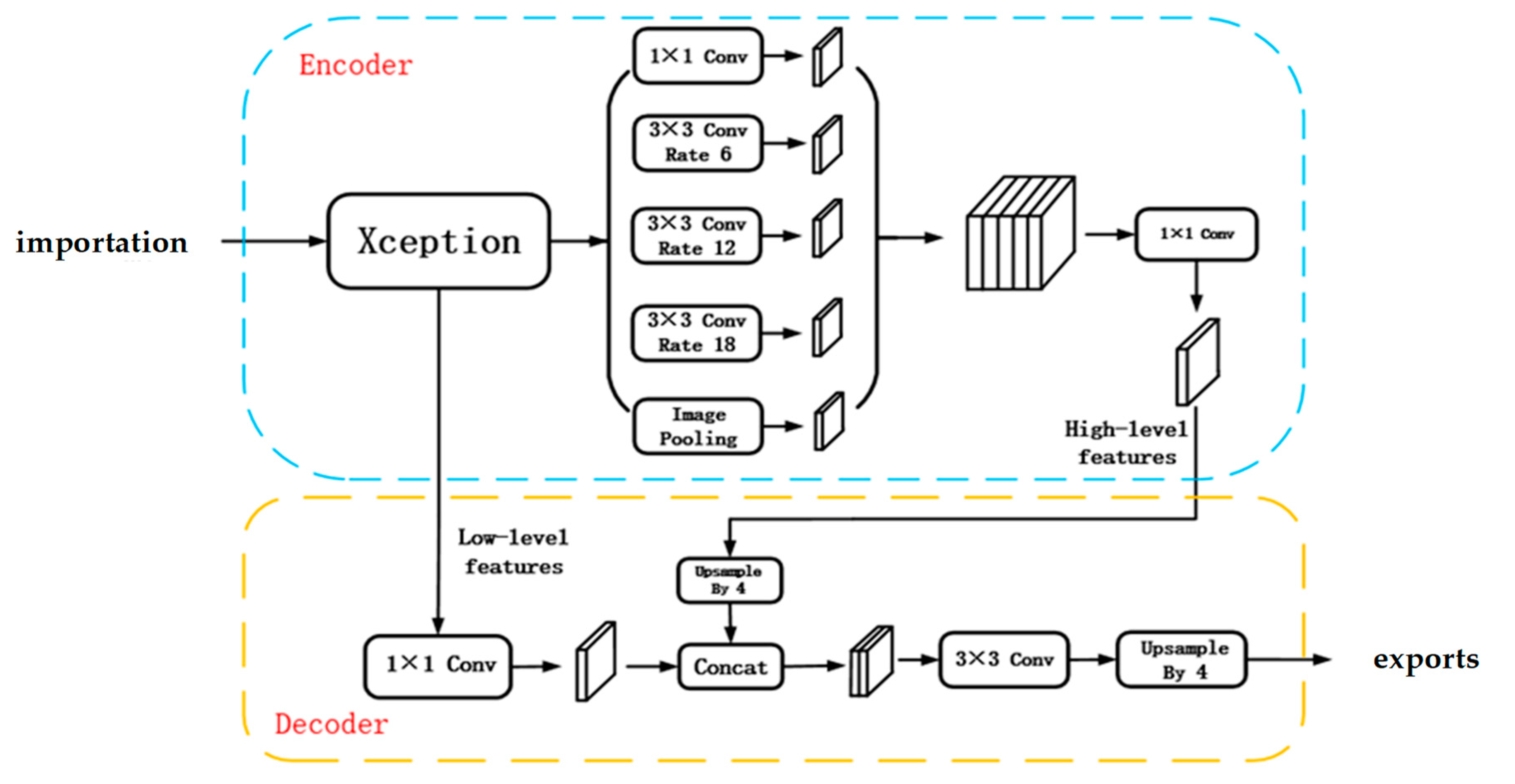
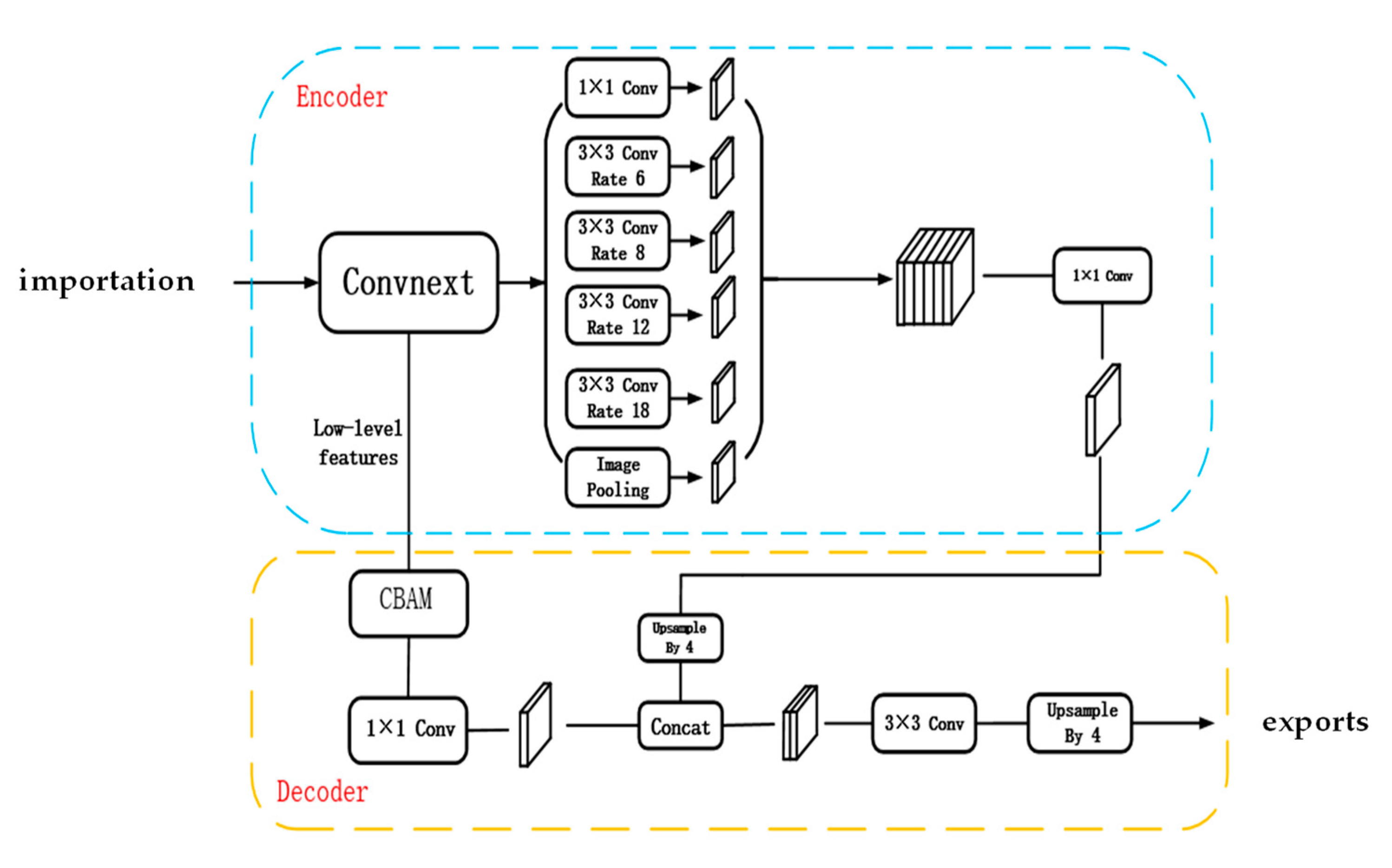
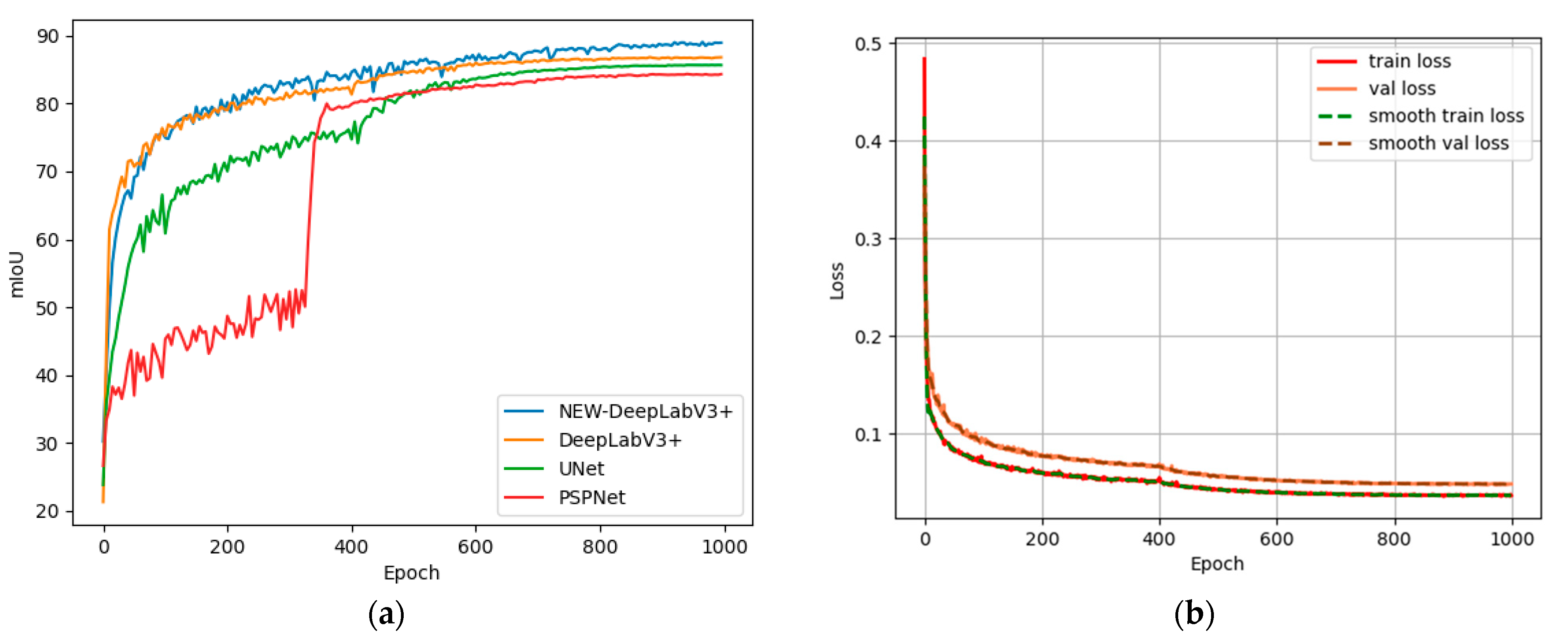
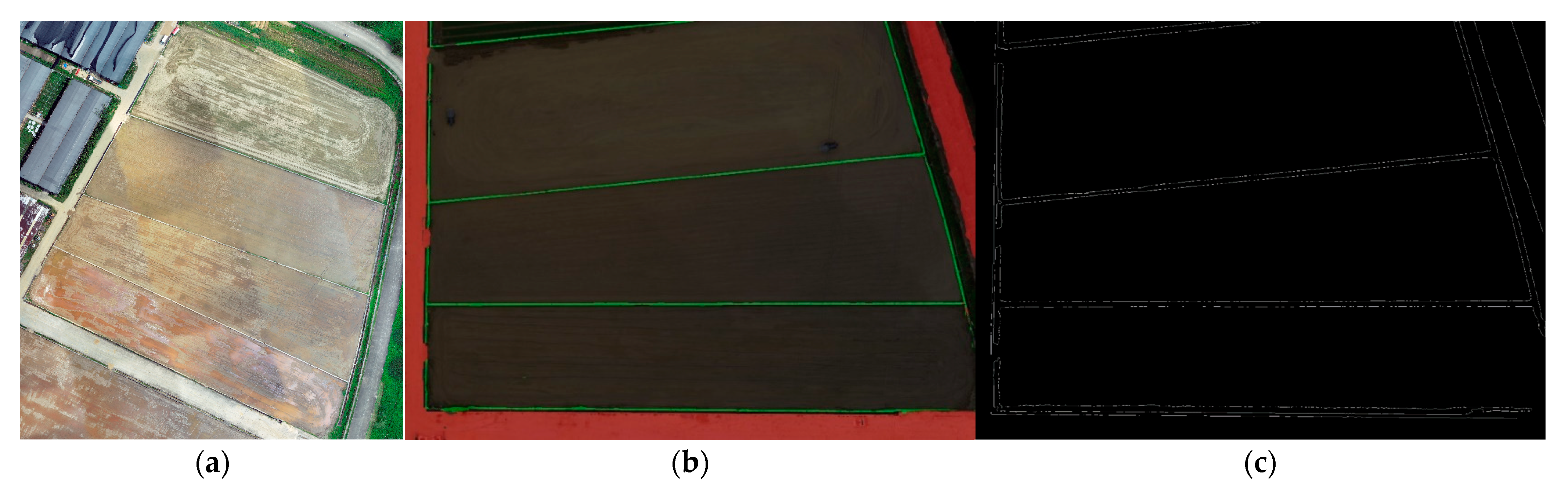
2.3.2. Identification of Field and Road Boundaries

In the process of unmanned farm development, the accurate and rapid acquisition of farmland boundary information and machine-tillage road locations is crucial for realizing the unmanned and precise operation of intelligent farm machinery, as well as for accurate farmland management. Presently, handheld RTK (real-time kinematic) methods are commonly employed to acquire farmland boundary and machine-tillage road information. However, with the increase in the number of farm plots, the manual workload has significantly escalated.
To address the need for accurate and swift acquisition of farm field and machine track boundary information, this paper proposes an enhanced UAV remote sensing image segmentation algorithm for field and machine track boundary segmentation utilizing DeepLabV3+. DeepLabV3+ is a semantic segmentation model that combines Encoder and Decoder components [31]. The Encoder utilizes the Xception backbone network and deep features extracted by Atrous Spatial Pyramid Pooling (ASPP) [32]. These features are then fed into the Decoder through upsampling, where they are fused with the original shallow feature map. Subsequently, upsampling is employed to restore the fused feature map to its original size [33]. The original structure of the DeepLabV3+ network is illustrated in Figure 3.
By enhancing the DeepLabV3+ algorithm, this study aims to mitigate the issues of incomplete boundary segmentation, adhesion, and breakage commonly observed in the traditional DeepLabV3+. The improvement of the DeepLabV3+ algorithm involves four key aspects:
(1)
Replacement of the backbone network
The ConvNeXt network is utilized in place of the conventional Res-Net (Residual Network) backbone network. In the ConvNeXt network, the convolution kernel size is increased from 3 × 3 to 7 × 7. It is observed that the learning capability of the network is positively correlated with the size of the convolution kernel, with the 7 × 7 kernel exhibiting the strongest learning ability. Additionally, the ReLU (Rectified Linear Unit) activation function in the ConvNeXt network is replaced by the GELU (Gaussian Error Linear Unit) activation function. This substitution leads to smoother gradients at 0, while also introducing negative values to the value domain range, thereby accelerating the convergence speed of the network.
(2)
Introduction of the CBAM attention mechanism
The CBAM mechanism is incorporated to mitigate feature loss. This mechanism involves spatial pooling and maximum pooling of the feature map to obtain two sets of 1 × 1 × C channels. Subsequently, these channels undergo processing by an MLP (Multilayer Perceptron) neural network. The results of this processing are then subjected to element-wise addition operation and activation by the sigmoid function to obtain the output results. The expression for channel attention processing is as follows:
M c F = σ M L P A v g P o o l F + M L P M a x P o o l F = σ ( W 1 W 0 F a v g c + W 1 ( W 0 ( F m a x c ) ) )
Following the channel attention processing of the feature maps, the results undergo pooling once for maximum pooling and once for average pooling. Subsequently, these results are concatenated by channel. The final weight coefficients are obtained after passing through a 7 × 7 convolutional layer and activation using a sigmoid function. This process can be expressed as follows:
M s F = σ f 7 × 7 A v g P o o l F ;   M a x P o o l F = σ ( f 7 × 7 ( [ F a v g s ; F m a x s ] ) )
where σ represents the sigmoid operation, and 7 × 7 denotes the size of the convolution kernel.
(3)
Improvement of ASPP
The primary aim of this study is to enhance model performance by modifying the parallel branch within the ASPP module. An additional branch with an expansion rate of 8 is introduced alongside the original ASPP module. Features extracted from each channel are fused using cascade operations, allowing for better consideration of subtle small-scale features and overall features through convolutions with varying expansion rates.
(4)
Hybrid Loss Function
The loss function characterizes the degree of disparity between the network’s predicted values and the actual values. In this paper, a hybrid loss function is proposed, which combines the Dice Loss and cross-entropy loss functions. This approach aims to address issues such as positive and negative category imbalance and gradient descent saturation during training. The expression for the hybrid loss function is as follows:
L o s s = L o s s d i c e   +   λ L o s s f o c a l   =   C     C = 0 C 1 T P ( c ) T P c + α F N c + β F P ( c )     λ 1 N C = 0 C 1 n = 1 N g n ( c ) ( 1 P n ( c ) ) 2 l n P n ( c )
where N is the total number of samples and C is the total number of labeling categories. TP(c) = n = 1 N g n ( c ) P n ( c ) , FN(c) = n = 1 N ( 1 P n ( c ) ) g n ( c ) , FP(c) =   n = 1 N P n ( c ) ( 1 g n ( c ) . P n ( c ) denotes whether category c is predicted at pixel location n, and g n ( c ) denotes whether the true category at pixel location n is category c. TP(c) represents the true positive rate of category c, FN(c) is the false negative rate of category c, and FP(c) is the false positive rate of category c. Parameters α and β in this model are both set to 1, and λ denotes the weight between L o s s f o c a l and L o s s d i c e . Different sizes are assigned based on the performance of the validation set; in this paper, we set λ = 1. The network structure of the improved DeepLabV3+ algorithm is depicted in Figure 4.
After performing semantic segmentation using the enhanced DeepLabV3+ segmentation algorithm, the semantic segmentation results undergo optimization through threshold segmentation and morphological processing via blob analysis. Subsequently, the Hough transform is employed to extract the boundary lines of the farmland and the machinery path. The obtained boundary lines are extended to fit any broken segments, and finally, the generated boundary layer information is integrated with the high-precision farm map.

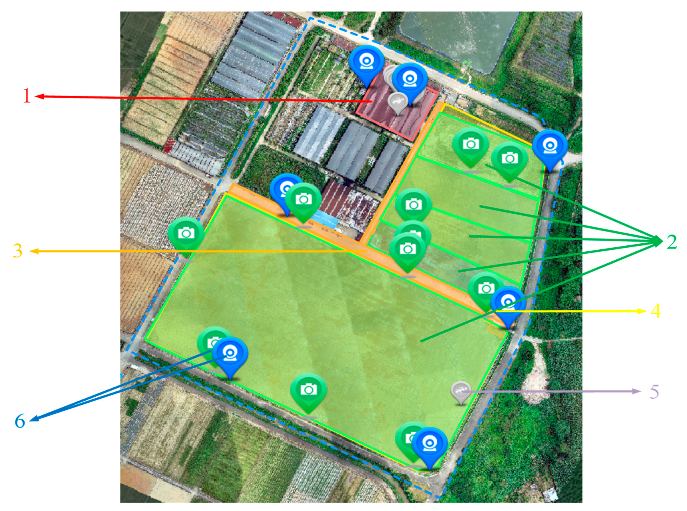
2.3.3. Farm Information Map Integration

To create a clearer and more intuitive representation of farm information, various data about the farm are integrated into a single map. The farm map information is categorized into three basic elements: the farm itself, the equipment, and the farm machinery, as illustrated in Figure 5. The basic element information is integrated with the platform through layers, while equipment points are obtained online via high-precision maps and data retrieval through third-party protocols. For intelligent farm machinery, standardized communication protocols are utilized to access and display information such as machinery location, online status, and operation trajectory on the map.

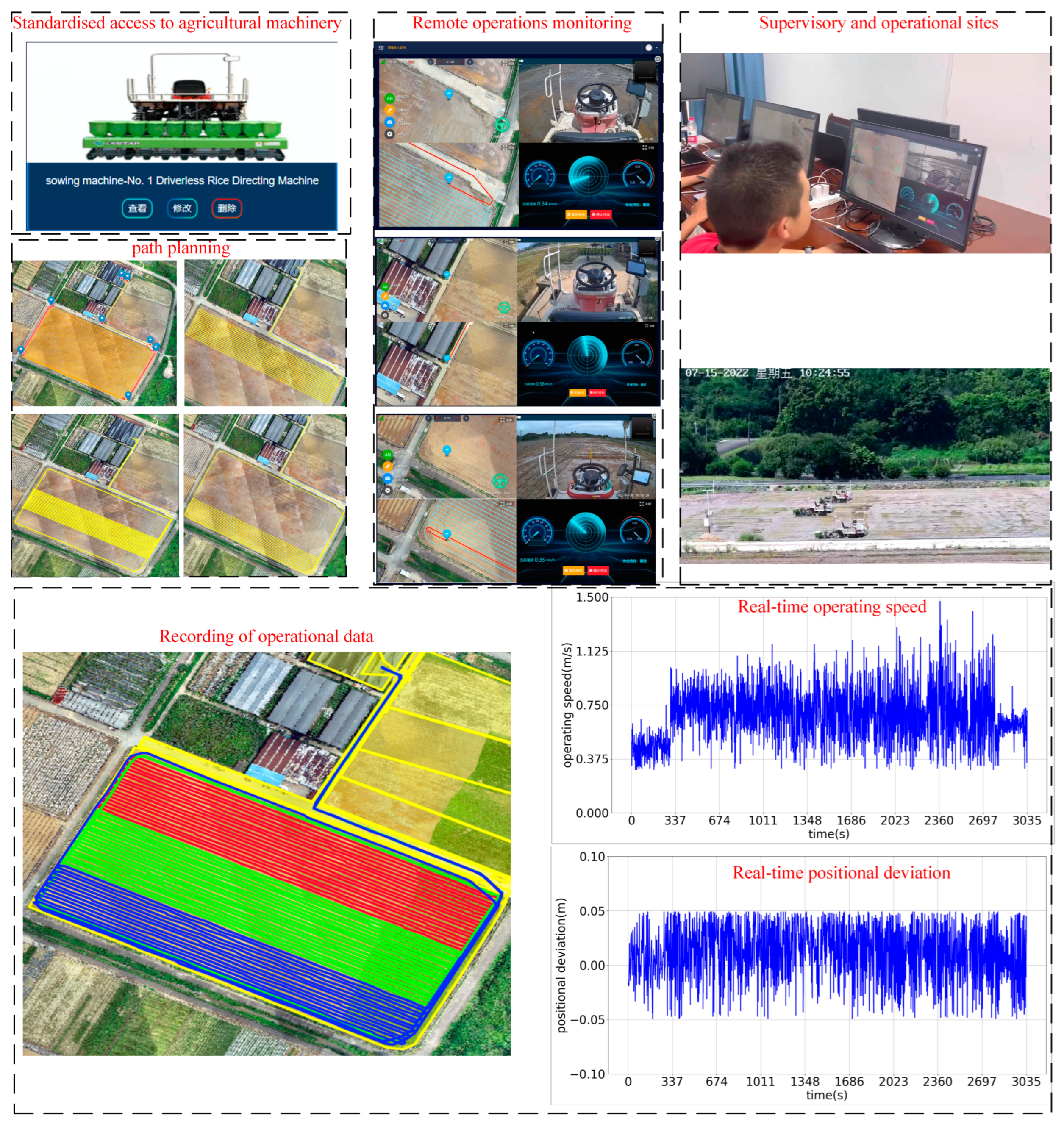
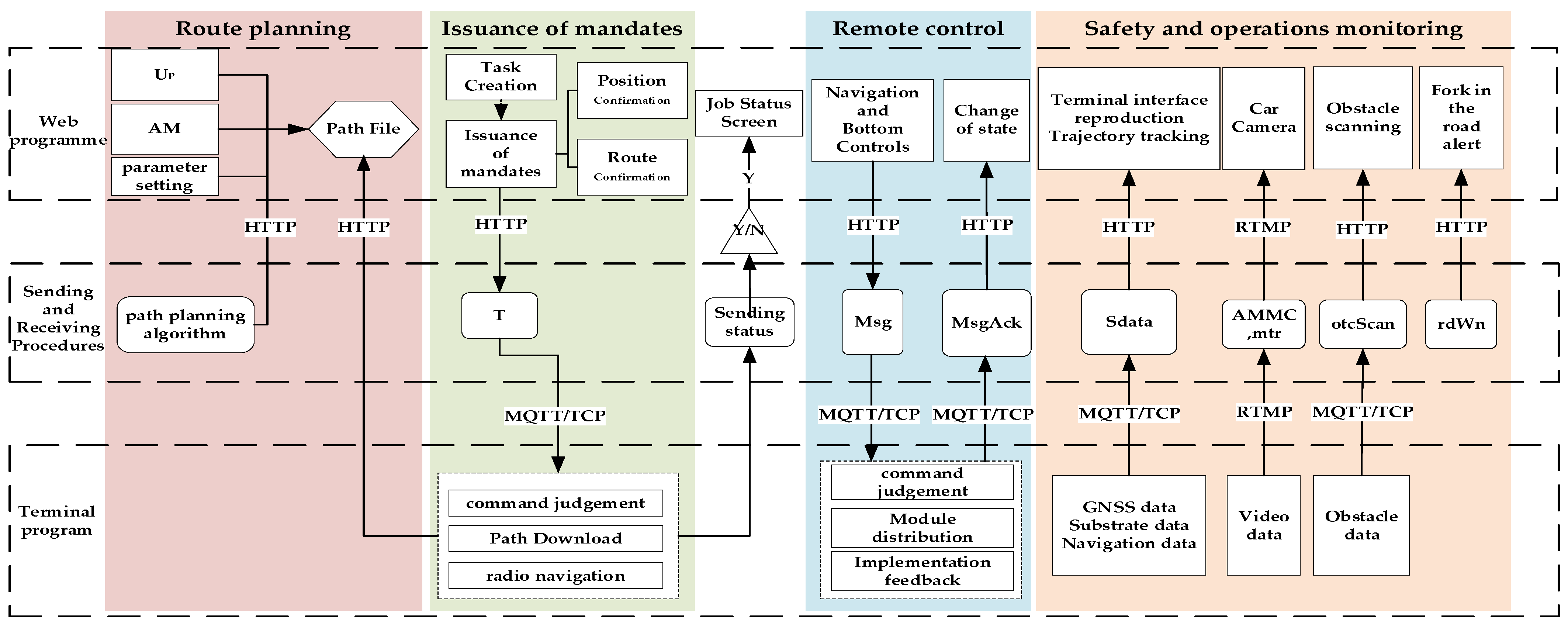
2.4. Remote Management and Control

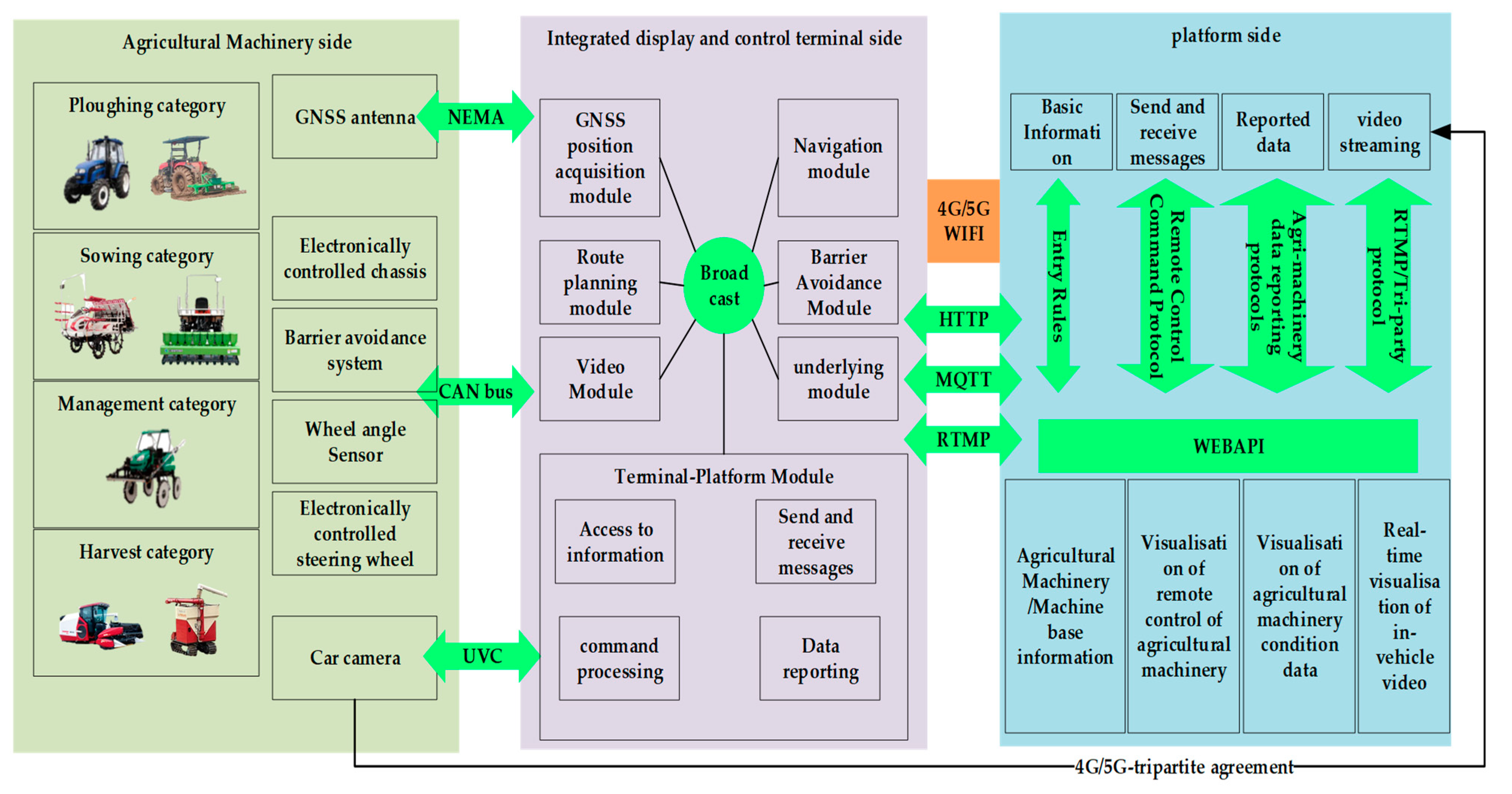
2.4.1. Standardized Access for Smart Farm Machinery

To enable the expandability, convenience, and practicality of accessing intelligent agricultural machines across different platforms, standardized docking protocols for cultivation, planting, management, and harvesting are formulated. A “three-level” protocol stack is devised for the intelligent farm machine, integrated display and control terminal, and platform, facilitating standardized access to the platform for information data reporting and command control of farm machine components and terminal modules. Based on the structural composition of intelligent agricultural machines and the one-to-one relationship between the integrated display and control terminal and the agricultural machine, the standard access relationship is divided into three categories: agricultural machine end and display/control terminal, agricultural machine end and platform end, and display/control terminal and platform end. The access protocol is further categorized into communication protocol and data protocol. The communication protocol determines the communication mode between different relationships, while the data protocol establishes communication data integration specifications. The standardized access design of intelligent farm machinery is depicted in Figure 6.
In Figure 6, concerning the relationship between the agricultural machine end and the display/control terminal, the NEMA (National Electrical Manufacturers Association) protocol is utilized to parse satellite signals for obtaining location information. The CAN bus is employed to receive information from the underlying modules of the agricultural machine as well as for command and control purposes. Additionally, the UVC (USB Video Class) protocol facilitates access to video and image data from the vehicle-mounted camera. For the relationship between the agricultural machine terminal and the platform terminal, a standardized integrated camera is directly connected to the platform. Regarding the relationship between the display/control terminal and the platform terminal, the HTTP protocol is utilized for file downloads and interface calls. The MQTT protocol is employed for message subscription and release between the display/control terminal and the platform terminal. Furthermore, the RTMP (Real-Time Messaging Protocol) is utilized for accessing video streams. Among the aforementioned protocols, the CAN bus, HTTP protocol, MQTT protocol, and broadcasting fall under communication protocols, while the NEMA protocol, UVC protocol, entry rules, remote control command protocol, agricultural machine data reporting protocol, and video streaming three-way protocol pertain to data structure protocols.

2.4.2. Remote Management and Control Model

(1)
Path Planning
The path planning design encompasses map point collection, inputting agricultural machine information, setting algorithm parameters, calling algorithms, visualizing the correction of erroneous points, and storing path files. Map point collection is accomplished through high-precision maps to gather data and establish data collections of boundary points and transport points:
U P = P b c , P m t , l P b c > 0 , l P m t 0
where P b c represents the collection of field boundary points and P m t represents the collection of transport points; l P b c denotes the length of the collection of field boundary points; and l P m t denotes the length of the collection of transport points. Constructing the input farm object A M ,
A M = { S N , t y p e O P , w i d O P , c a p O P , s p e e d R , o i l O P , o i l U O P , t u r n T , O P T , l o c M , r , l }
where SN denotes the terminal serial number to which the farm machine is bound, t y p e O P denotes the operation type, w i d O P denotes the operation width, c a p O P denotes the operation capability, s p e e d R denotes the road speed, o i l O P denotes the fuel consumption during operation, o i l U O P denotes the non-operation fuel consumption, t u r n T denotes the turnaround time, O P T denotes the day during which the farm machine operates, l o c M denotes the position of the farm machine, r denotes the turnaround radius, and l denotes the distance from the control point of the farm machine to the end of the machine w i d O P ,     r ,     l , which is utilized solely for path planning. The path planning algorithm parameter settings include path type, turning mode, whether to close the loop, and whether to group.
(2)
Remote Task
The remote task is devised to transmit the path file to the designated intelligent farm machine. To ensure the uniqueness of the intelligent farm machine’s ID, the serial number of the integrated display and control terminal is utilized as a variable to generate the message subject. The task-sending process design comprises task creation, security confirmation, path file transmission, downloading and activation of the intelligent farm machine path, and message feedback. The task object is constructed following the requirements of agricultural machine operation:
T = { t k I D , f a r , f l d , t k T p , A M , r o u t e , c t T i m e , s t a }   and   f a r f l d , A M , r o u t e ,   f l d & t k T p r o u t e
where t k I D denotes the task sequence number, f a r denotes the farm, f i e l d denotes the field, t k T p denotes the task type, A M denotes the farm machine object, r o u t e denotes the path file, c t T i m e denotes the creation time, and s t a denotes the task status. Constraints are imposed on the field, farm machine, and path; the farm determines the selection of the field, farm machine, and path; and the field and the type of operation determine the selection of the path. The command message data object Msg and feedback message data object are constructed according to the task object and farm machine object M s g A c k ,
M s g = m s g I D , S N , t k I D , c m d C d , l i n k , e p t , S N A M , t k I D T
M s g A c k = m s g I D , r e s I D , S N , t k I D , c m d C d , r e s F l a g , e p t , r e s I D M s g , S N A M , t k I D T , r e s F l a g { 1,2 }
where m s g I D denotes a message sequence number, c m d C d denotes an instruction code, l i n k denotes a path link, e p t denotes the content of the message description, r e s I D denotes a feedback message sequence number, and r e s F l a g denotes the result of message execution, with 1 indicating success and 2 indicating failure.
(3)
Remote Control
Remote control is divided into the control of the intelligent agricultural machinery navigation and the bottom, using the implementation of the control of different modules, taking the value of the definition of the design of Table 1.
(4)
Safety system
Intelligent farm machinery operation safety and operation quality monitoring is an important part of remote control. The establishment of agricultural machinery reporting data objects to monitor the status of agricultural machinery:
S d a t a = d a t a I D , S N , c l t T i m e , d v c S t a , t k I D , c h s , G N S S , a t c , S N A M , t k I D T
where dataID denotes the packet sequence number, cltTime denotes the acquisition time, d v c S t a denotes the navigation status of farm machinery, c h s denotes the underlying data, GNSS denotes the GNSS position data, and a t c denotes the navigation data. Integration of farm multi-intelligent devices to monitor the environmental safety and operation quality of smart farm machine operations and construction of environmental data objects E v t is
E v t = { m t r , A M M C , r d W n , o t c S c a n }
where m t r denotes farm monitoring data; A M M C denotes video data from the onboard camera of the farm machine to view the forward direction environment, the cockpit environment, and the effect of the operation of the farm machine; r d W n denotes turnoff blind zone warning data, which provides early warning information for the smart farm machine when it shifts on the road; and o t c S c a n denotes obstacle scanning data of the smart farm machine, which performs obstacle scanning for the smart farm machine’s forward direction, at a distance that can be customized.
Through the data model design results of path planning, remote task, remote control, and safety system, the three-part remote control model comprising the web end, transceiver end, and intelligent farm machinery terminal is constructed, as illustrated in Figure 7.

2.4.3. Multi-Agricultural Machinery Management and Control

There are various types of intelligent farm machines on the farm, and multiple types of operation tasks occur simultaneously. Additionally, there are constraints on the order of agricultural tasks and operational conditions between different operation types. Therefore, operation types are categorized based on agricultural tasks, and their sequence and interval times are determined. The fulfillment of operation conditions is assessed using data from farm sensing equipment. Online tasks are then established for different types of agricultural tasks, with their starting times set accordingly. Concurrently, the safety and operation processes are controlled by establishing a collaborative network of multiple farm machines based on the logical model of remote control. During operations, to oversee various types or multiple scenarios involving intelligent farm machinery, a multi-agricultural machinery cooperative network is established based on the remote control logical model. This enables simultaneous control of agricultural machinery operation safety and processes. Cooperative control of multiple types of agricultural machines primarily achieves unified control of operating agricultural machines. It also allows for the display of operation statuses and distributions of all agricultural machines through a single interface, facilitating monitoring of safety and operations.
The management and control process is designed as follows: (1) Create a plowing, planting, management, and harvesting type operation task T s = { T 1 , T 2 , , T n } . (2) Select multiple tasks T k ( T k ϵ T s ) to join the collaborative group network, acquire task data, and issue tasks. (3) According to the acquired task data, display the field area, planned path, and location of farm machinery of all tasks in the high-precision map visualization. (4) Establish unique farm machine message topics and use different values of c m d C d ( c m d C d M s g ) to achieve remote control of farm machines in the network, and monitor safe operations based on S d a t a and E v t object data.

2.5. Experimental Area and Materials

The test site selected was the Zengcheng Teaching and Research Base of South China Agricultural University (SCAU), comprising four high-standard farmlands, concrete mechanized plowing paths, and agricultural machinery storage facilities, covering an area of approximately 80 acres, as depicted in Figure 8.
(1)
High-precision map construction test materials
The high-precision map construction process includes farm image acquisition and original map construction, boundary recognition of fields and roads, and farm information map integration. In the construction process, the materials used are shown in Table 2.
To verify the accuracy of the map, an accuracy comparison was conducted using RTK field collection and map collection to validate the point information. For field collection, the Huasi i70 intelligent RTK was selected, with its main parameters shown in Table 3.
(2)
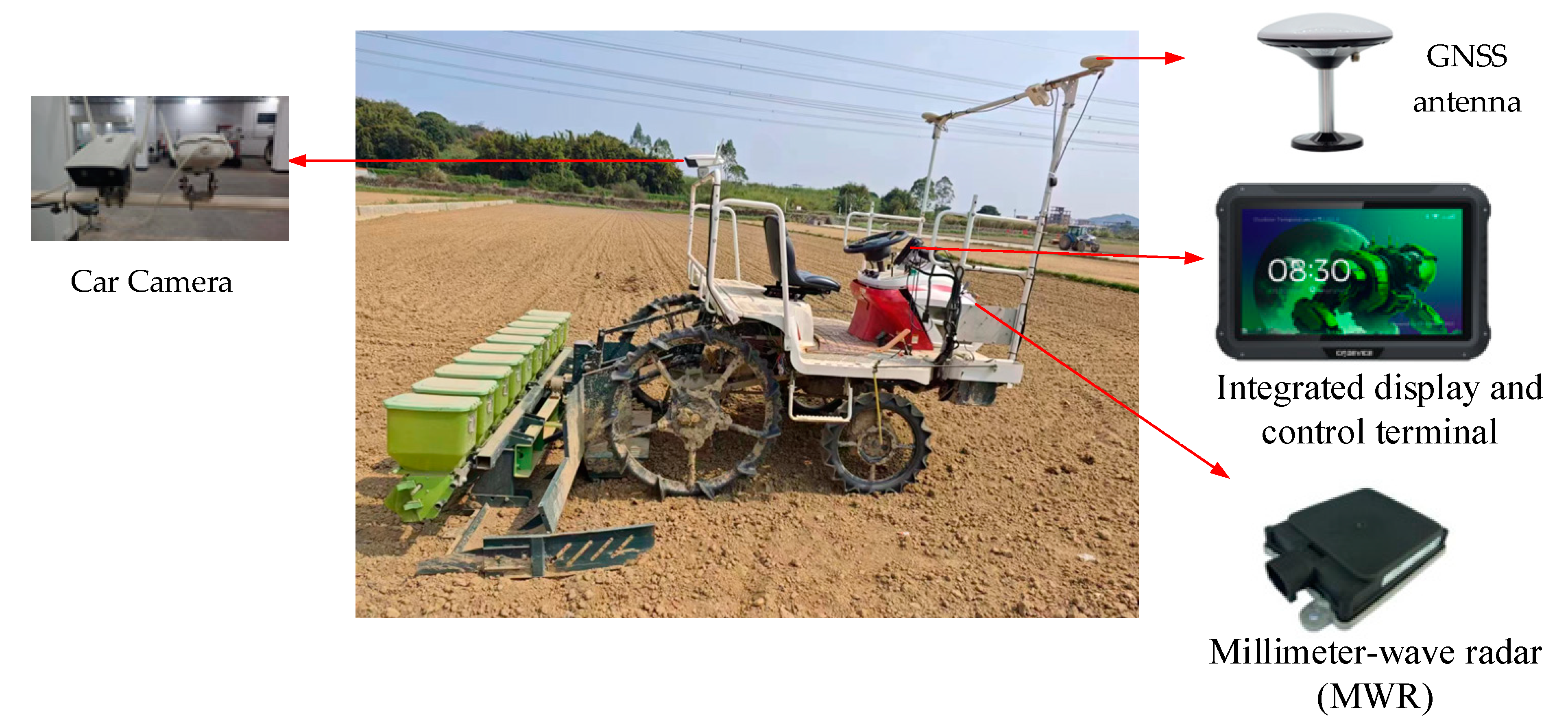
Remote Control Test Materials
The rice directing machines comprised three sets of Seydal Star2BDXZ-10SCA (20) self-propelled rice hole directing machines equipped with self-developed unmanned systems, as depicted in Figure 9. These agricultural machines are equipped with GNSS (Global Navigation Satellite System) antennas, electronically controlled steering wheels, wheel angle sensors, electronically controlled chassis, obstacle avoidance systems, on-board cameras, and integrated display and control terminals. They feature wire-controlled clutch, implement, throttle, and gear systems, with the steering control equipped with electronically controlled steering wheels and wheel angle sensors. The unmanned system consists of an integrated display control terminal and GNSS antenna. The display and control terminal integrates a high-precision BeiDou positioning module, providing a positioning accuracy of ±1 cm, while the controller’s linear navigation control accuracy is ±2.5 cm. Additionally, it integrates a 4G communication module. Each live broadcasting machine is equipped with a millimeter-wave obstacle avoidance radar, with a dynamically adjustable scanning range. Moreover, it is installed with front and rear onboard cameras, enabling remote monitoring of cockpit status and operational effects through the wireless network.
To enable remote control, a computer, tablet, or mobile phone with network communication capability is utilized. The platform’s link address is accessed through a web browser, and the unmanned farm in Zengcheng is selected to remotely control the operation of agricultural machinery.

2.6. Experimental Design

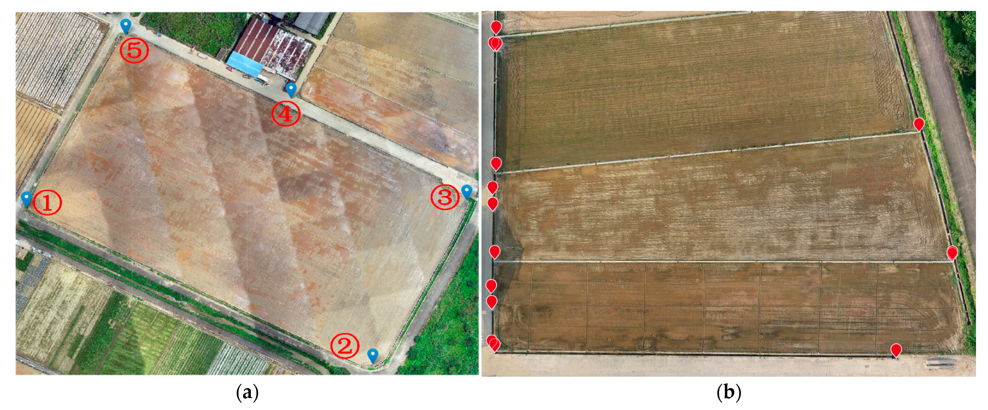
2.6.1. High-Precision Map Construction Test

For the improved recognition algorithm, performance verification tests and application tests were designed. The UAV was employed to partition the farm map in clear weather. The flight parameter settings included a flight altitude set to 100 m, with a ground sampling distance (GSD) capable of reaching 2.74 cm. The flight speed was set to 8 km/h, with a heading overlap rate and bypass overlap rate of 70%, and a time interval for taking pictures of 2 s. The images captured during the flight were imported into DJI Zhitu software to establish a two-dimensional creation task. The output coordinate system used was the WGS 84 geodetic coordinate system. The sampled data was spliced to obtain the farm map, and the reconstructed farm map was employed to crop the remote sensing image of the farm using OpenCV. Each small image block was set to a size of 512 × 512 pixels to construct the dataset. The semantic segmentation model was trained with 4000 images under the same parameters, and the model performance was tested with 1000 images. Evaluation metrics such as mean intersection over union ratio (mIoU), mean pixel accuracy (MPA), and training loss function were selected to assess the performance of the network. mIoU represents the ratio of intersection and union of the standard image and the manually annotated image computed by the network prediction. MPA denotes the number of pixels correctly discriminated as class I but incorrectly discriminated as class II. The calculation formulas are as follows:
m I o U = 1 k + 1 n = 0 k P n n m = 0 k P m n + m = 0 k P m n P m m
M P A = 1 k + 1 i = 0 k P i i j = 0 k P i j
where k denotes the number of categories. P m n denotes the number of false-negative examples. K + 1 denotes that the number of categories contains a class of background. P n n denotes the number of pixels of true examples. P n m denotes the number of pixels of false-positive examples. P i i denotes the number of pixels that are accurately discriminated as class i. P i j denotes the amount of pixels that are correctly discriminated as class i, but are incorrectly discriminated as class j. P j i denotes the amount of pixels that are correctly discriminated as class j, but are incorrectly discriminated as class i. In this study, a hybrid loss function combining the cross-entropy loss function and the Dice Loss loss function is chosen.
After verifying the improved recognition algorithm, image data are collected from the test area according to the aforementioned dataset construction method, and the dataset is generated. The improved semantic segmentation model is then applied to predict the small image blocks after cropping. Finally, the small modules are spliced together, and boundary lines are extracted to generate the farm road and field recognition layer. The existing equipment and farm machinery in the farm are accessed and integrated on the map. The accuracy of the completed map is verified by selecting the 5 points shown in Figure 10a. The coordinate system used for GPS positioning in this paper is the WGS-84 geodetic coordinate system, and the planar projection used is the “Gauss-Kruger” projection, which transforms the collected point information into a spatial Cartesian coordinate system for comparison. Fifteen feature points, such as the vertices of parcels 2–4 and the inflection points of the ploughing road, were selected for accuracy verification, as shown in Figure 10b. The manual point information was then compared with the extracted information, and the extraction results of the experimental area were evaluated using the indicators of boundary extraction completeness (COR) and accuracy (COM). The calculation formulas were as follows:
C O R = T P T P + F P
C O M = T P T P + F N
where FP is the length of the correct linear region (number of pixel points) that was extracted, FN is the length of the region that was not extracted, and TP is the length of the correctly extracted road region.

2.6.2. Remote Control Experiment

Verification tests and application tests were designed for the remote control method. Communication tests were conducted using the integrated display and control terminal, and the frequency of data interaction for standardized access to agricultural machinery information was verified and tested. The path planning accuracy test involved formulating paths using a platform and testing the position display accuracy on the machine plowing path using an unmanned live machine. Additionally, the real-time data interaction of the remote control and safety system during the operation of agricultural machinery was verified.
Upon verifying the feasibility of the remote control method, the platform was designed to control the “3-machine simultaneous operation” application test in the test area. A large field with an area of 50 acres in plot 1 was selected as the operation field, and three unmanned broadcasting machines were used as the control objects. Path planning requirements for three sets of agricultural machinery were established from the hangar to the road transport to plot 1. The field operation was divided into three non-interfering pieces with full-coverage paths. Path planning parameters were designed as outlined in Table 4. Tasks were sent through the platform to achieve the simultaneous operation of the three sets of agricultural machinery in the remote control test.

3. Results

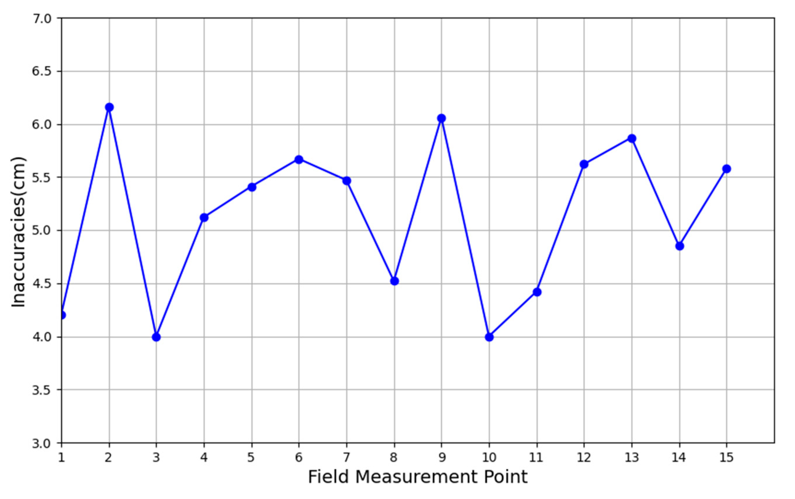
3.1. High-Precision Map Construction Results

The comparison with other mainstream recognition algorithms is depicted in Figure 11. In Figure 11a, the algorithm proposed in this paper demonstrates a 4.64% higher mIoU value compared to the PSPNet algorithm, a 3.28% higher mIoU value relative to the UNet algorithm, and a 3.15% higher mIoU value compared to the original DeepLabV3+ algorithm. The training loss curves are illustrated in Figure 11b, where the solid line graph represents the training loss curve for the model’s training set described in this study, and the dashed line represents the loss curve for the test set. From the loss function curve in Figure 11b, it can be observed that during the pre-training period, the loss rate decreases rapidly and exhibits a continuous oscillation phase. As the number of training iterations increases, the loss rate gradually decreases and approaches convergence, indicating the stabilization of the model.
A comparison of the recognition results with the original DeepLabV3+ algorithm for roads, concrete ridges, and earthen field plowing is shown in Table 5. The MPA is improved by 3.8 percentage points compared to the original DeepLabV3+ model.
The recognition results of farmland and the mechanic road are depicted in Figure 11, with the splicing results presented in Figure 12b. For the segmentation outcomes, farmland and road boundary line information is extracted using blob analysis and Hough transform. Semantic segmentation results are further optimized through threshold segmentation and morphological processing to eliminate noise patches caused by interfering field information, with the optimization results showcased in Figure 12c.
The verification of the accuracy of the acquired raw maps is shown in Table 6. The maximum error of the five points is 3.2 cm, and the average error of the five points is 2.98 cm. The error of the points of the high-precision map constructed by UAV is less than 3 cm.
The result of accuracy verification of the recognition results after recognition using the 15 feature points selected above is shown in Figure 13. The error range of the 15 target points selected for the concrete ridges and roads falls between 4–7 cm, with the maximum deviation being 6.16 cm and the average absolute error being 5.15 cm.
The recognition results were analyzed using completeness and accuracy rates. The completeness rate of the boundary line extraction for the concrete ridge and road is 96.71%, with a correct extraction rate of 95.63%. These findings indicate that the boundary recognition algorithm can achieve precise and complete extraction of the boundaries of the farm machinist’s road and farmland with high accuracy.
In conclusion, the accuracy of high-precision maps and the accuracy of recognition meet the needs of unmanned agricultural machine operations. Utilizing the recognition algorithm, the field and road area layers are generated, and obstacles are collected in the high-precision map to generate the area layer for hangar boundary points. These layers are then released as an online service and integrated into the farm map. Completion of access for sensing equipment and intelligent farm machinery results in the generation of the overall farm map. The construction of the platform map is depicted in Figure 14.

3.2. Remote Management Test Results

Using the amount of data received by the platform to test the frequency of reporting data from agricultural machines, the terminal connects to the MQTT server and sets the message publishing level QoS to 0. It then pushes 100 pieces of data to the platform using reporting frequencies of 0.5 Hz, 1 Hz, and 2 Hz, respectively, and evaluates them according to the packet loss rate, data correctness rate, and real-time performance. The results are shown in Table 7.
As shown in Table 7, at reporting frequencies of 0.5 Hz and 1 Hz, the packet loss rate and data correctness are optimal. However, at 1 Hz frequency, real-time performance is higher, indicating more intensive data transmission over time. Conversely, using a 2 Hz reporting frequency resulted in packet loss and data correctness issues. The analysis suggests that packet loss may stem from the QoS level settings. Increasing QoS levels from low to high improves message reliability but also increases transmission complexity, making it less suitable for high-frequency scenarios. Additionally, the decrease in data correctness may be attributed to inconsistencies in terminal information acquisition and data reporting at different frequencies, leading to inaccurate data readings. Based on this analysis, it is concluded that a reporting frequency of 1 Hz for agricultural machinery aligns better with the operational requirements of intelligent agricultural machinery.
The validation of the path planning results is shown in Table 8. The relative error of the trajectory of agricultural machinery operation on the high-precision map is around 2 cm.
For the update of farm machinery trajectories, control instructions, and real-time video validation, the validation results are presented in Table 9. Trajectory updates occur at a rate of 1 s per point, dependent on the frequency of data reported by the farm machine. Sending control command messages and receiving feedback takes only 0.28 s.
In summary, the communication, path error, and real-time verification of agricultural machines meet the requirements of remote control of agricultural machines. According to the platform architecture design, the platform integrates the corresponding functions. The results of the field operation control test conducted on smart agricultural machines using the platform are depicted in Figure 15. They are integrated into the platform as described in the appeal. Following the remote control process, the steps of farm machine access, path planning, remote task execution, and safety monitoring are carried out sequentially, and records of completed operations are tallied.
For the completion of operations, path tracking, error calculation, filtering of traps, and averaging of large data fluctuations, statistical analysis was performed on various parameters, including the average speed of agricultural machinery during operation and completion time. The statistical results are presented in Table 10.
During the test, one person successfully conducted the control operation of three farm machinery operations. The entire process, including path planning, remote task assignment, remote control, and safety system monitoring of intelligent farm machinery operations, was achieved with high real-time performance and visual supervision through remote access.

4. Discuss

4.1. Analysis of Results

The results of high-precision map construction are analyzed for comparison based on recognition accuracy and acquisition efficiency. In the performance verification results, the mean pixel accuracy (MPA) is 95.31% and the mean intersection over union (mIoU) is 88.96%. Additionally, the extraction completeness rate is 96.71%, and the extraction correctness rate is 95.63% in the application experiments. Currently, manual labeling methods are primarily used for farmland identification, often relying on agricultural experts’ accumulated experience and relevant theoretical knowledge. For instance, Wang Yuli et al. [33] employed software tools like ArcGIS and ENVI to manually decode and analyze multispectral images of cultivated land in the Xinjiang region, generating maps through layer overlay. Although simpler to operate, manual annotation methods for farmland identification suffer from lower accuracy and efficiency. Ming Dongping et al. [34] utilized spatial statistics and threshold segmentation methods to extract farmland from remote sensing images, achieving an overall accuracy of 84.15% and enhancing the efficiency and automation of farmland extraction. However, simple machine vision approaches require high-quality remote sensing images and lack generality and robustness. Ji Xusheng [35] accomplished the rapid and accurate acquisition of small field boundaries through edge detection and morphological processing of farmland, achieving a farmland-matching completion rate of 85%. Meanwhile, Liu Dong et al. [36] proposed a farmland boundary identification method based on the normalized vegetation index, utilizing threshold segmentation and the Canny operator edge detection method to achieve effective segmentation of farmland boundaries. Deng Hong et al. [37] introduced a deep learning-based semantic segmentation algorithm for UAV water field images, enhancing the segmentation accuracy by improving the DeepLabV3+ network. After testing, they obtained a mIoU of up to 85.90%. Compared to existing research results, the method proposed in this paper demonstrates high efficiency and accuracy in farmland and road recognition. It can potentially replace manual parcel and road annotation methods, leading to reduced labor costs and investment.
In the process of conducting remote control application tests, the effectiveness of remote control is analyzed based on labor cost considerations. Presently, traditional operations of intelligent farm machinery entail pre-operation preparations, on-site supervision during operations, and post-operation data analysis. Pre-operation tasks involve collecting point information on the farm for path planning and debugging machinery data. During operations, technicians are required to operate integrated display and control terminals on-site to issue tasks, initiate operations, and monitor machinery status. After completion, data is then copied and analyzed. In the “Three rice seeders simultaneous operation” test scenario, only one person is required to manage machinery operations. In contrast, traditional supervision methods for intelligent machinery operations require three individuals to oversee three machines simultaneously, necessitating more personnel with advanced skills such as field point collection and unmanned system operation. Traditional methods of acquiring agricultural machinery operation information are limited and less comprehensive, while the concentrated visualization of operation information enhances supervision quality and data acquisition efficiency compared to conventional methods. Consequently, the approach presented in this paper reduces the need for multiple participants, lowers technical skill requirements for controllers, and enhances the quality of control over intelligent agricultural machinery operations.

4.2. Platform Comparison

The unmanned farm intelligent farm machinery operation control platform proposed in this paper aims to provide precise services for intelligent farm machinery operations, offering three distinct advantages over existing control platforms. Firstly, it offers rapidly constructed and highly available high-precision maps that facilitate online point collection and diversified information visualization [19]. Compared to existing high-precision map geographic information annotation methods, which often rely on manual map annotation or on-site point collection, the approach presented in this paper leverages machine learning algorithms to efficiently identify fields and roads utilized in agricultural machinery operations, generating boundary layers to achieve platform integration. The completeness and correctness of the recognition results are verified through experiments, enhancing the efficiency of data collection.
Secondly, it incorporates remote control technology for the entire chain of intelligent agricultural machinery operations [38,39,40]. While current control platforms primarily focus on specific types of farm machinery or segments of the machinery control process, this paper establishes protocol unification across the entire machinery chain by developing communication protocols for farm machinery, terminals, and platforms. This approach provides users with convenient access to farm machinery and enhances the richness of operation information supervision. Existing platforms typically offer limited services for the entire process of intelligent farm machinery operation and lack comprehensive supervision of operational information. In contrast, this paper comprehensively addresses the operational services of farm machinery before, during, and after operations, not only reducing labor costs but also significantly improving supervision quality.
Finally, the platform architecture proposed in this paper can better serve agricultural machinery operations. From a software perspective, the platform presented herein demonstrates superior performance, addressing the issue of slow uploading and loading of traditional maps through optimized map uploading methods. The remote control validation test illustrates the platform’s high real-time communication capability. Moreover, it exhibits robust security features, leveraging GateWay gateway, SpringSecurity, OAuth2, and farm unique ID to generate tokens, ensuring data security. From the user’s standpoint, the platform offers high usability. The construction of high-precision farm maps and remote control tests verify the platform’s ability to visualize farm information and farm machinery operations effectively. Additionally, it achieves functional division for the process of farm machinery operations, thereby reducing users’ technical difficulties in utilization. Regarding application services, the platform has been implemented in 30 unmanned farms since its inception. Users’ evaluations of map construction and operation control are positive, with a high level of acceptance for the control functionalities.

5. Conclusions

In this paper, we propose a control platform for intelligent farm machinery operations, focusing on an unmanned farm as an implementation scenario. This platform enables remote control of farm machinery equipped with unmanned systems. To simplify implementation complexity and enhance platform scalability, we adopt a layered platform architecture tailored to the needs and processes of farm machine operations. Our platform utilizes UAV recognition integration to achieve high-precision and efficient construction of farm maps. Field tests confirm map construction errors of less than 3 cm and field/road recognition errors of 5.15 cm, validating the feasibility of the map application. We introduce a remote control method for intelligent farm machinery operation, alongside a “three-level” protocol stack for standardized access to multiple farm machinery types, facilitating remote control throughout the operational process. Field test results demonstrate that our method reduces the number of personnel involved in production compared to traditional methods, while also lowering technical requirements and simplifying operation procedures, thereby enhancing control quality and positively contributing to unmanned farm realization.
The application of our intelligent farm machinery operation control platform offers two key benefits to unmanned farms. Firstly, the high-precision map serves as the foundation for smooth operation implementation. Users can leverage the platform to construct detailed maps reflecting the farm’s actual conditions accurately, including fields, roads, and integrated sensing information, thereby improving information acquisition efficiency. Secondly, our platform considers the entire agricultural machinery operation process and implements functional division, enabling one-button management of farm machinery within the farm, streamlining operation procedures and reducing labor costs.
Our proposed control method, rooted in the study of agricultural machines equipped with unmanned systems, offers modularity for access by intelligent robots and drones in unmanned farms. By analyzing the operation processes of different production equipment, we develop remote control methods and formulate standardized access protocols to control other highly intelligent production equipment on the farm. Looking ahead, we envision the unmanned farm control platform evolving towards smarter functionalities, integrating the latest technology to cater to personalized and refined agricultural production needs, as well as managing complex agricultural machinery operation scenarios. Future work will focus on researching multi-type intelligent equipment control methods and cooperative operation scheduling methods.

Author Contributions

Conceptualization, M.Y., P.W., X.L. and L.Y.; methodology, M.Y., P.W., L.Y. and L.H.; software, M.Y., P.W., L.Y., Z.M., D.F. and Y.D.; validation, M.Y., P.W., L.Y., S.L. and C.L.; formal analysis, M.Y., P.W. and L.Y.; investigation, M.Y., P.W., Z.M. and S.L.; resources, L.H., X.L., J.H. and P.W.; data curation, M.Y., P.W., L.H., J.H. and L.Y.; writing—original draft preparation, M.Y., P.W. and L.Y.; writing—review and editing, M.Y., P.W., L.H., X.L. and J.H.; visualization, M.Y., P.W., H.H., D.F. and Z.M.; supervision, X.L., L.H., J.H. and P.W.; project administration, L.H.; funding acquisition, X.L., L.H. and J.H. All authors have read and agreed to the published version of the manuscript.

Funding

This research was funded by the National Key Research and Development Program of China (Grant No.2022YFD200150502), the Science and Technology Planning Project of Guangdong Province (Grant No.2023B0202010023), and the project of Specialized Discipline of Specific Universities (Grant No.2023B10564002).

Data Availability Statement

The data that support this study will be shared upon reasonable request to the corresponding author.

Acknowledgments

We would like to thank our partners at the Zengcheng Teaching Base of South China Agricultural University and Anhui Zhongke Intelligent Sense Industrial Technology Research Institute.

Conflicts of Interest

The authors declare no conflicts of interest.

References

  1. Luo, X.W.; Liao, J.; Zang, Y.; Ou, Y.G.; Wang, P. Developing from Mechanized to Smart Agricultural Production in China. Strateg. Study CAE 2022, 24, 46–54. [Google Scholar] [CrossRef]
  2. Zhao, C.J.; Fan, B.B.; Li, J.; Feng, Q.C. Agricultural Robots: Technology Progress, Challenges and Trends. Smart Agric. 2023, 5, 1–15. [Google Scholar]
  3. Zhou, X.S.; Fan, S.G. Solving the Problem of “Who Will Grow Grain”: The Foundation and Path of Comprehensively Promoting Agricultural Mechanization. Acad. J. Zhongzhou 2023, 45, 54–60. [Google Scholar]
  4. Wu, Y.H.; Wang, H.S.; Zhou, R.Z.; Zhu, N.; Zhang, X.W. Regional differences and convergence characteristics of comprehensive development level of agricultural mechanization. J. Chin. Agric. Mech. 2024, 45, 311–319. [Google Scholar] [CrossRef]
  5. Chu, B.Q.; Li, C.F.; Ding, L.; Guo, Z.Y.; Wang, S.Y.; Sun, W.J.; Jin, W.Y.; He, Y. Nondestructive and Rapid Determination of Carbohydrate and Protein in T. obliquus Based on Hyperspectral Imaging Technology. Spectrosc. Spectr. Anal. 2023, 43, 3732–3741. [Google Scholar]
  6. Sun, J.L.; Li, D.H.; Xu, S.W.; Wu, W.B.; Yang, Y.P. Development Strategy of Agricultural Big Data and Information Infrastructure. Strateg. Study CAE 2021, 23, 10–18. [Google Scholar] [CrossRef]
  7. Wang, J.F. Research on Development Situation of Big Data Application in the Era of Smart Agriculture. J. Tech. Econ. Manag. 2020, 41, 124–128. [Google Scholar]
  8. Zhao, B.; Zhang, W.P.; Yuan, Y.W.; Wang, F.Z.; Zhou, L.M.; Niu, K. Research Progress in Information Technology for Agricultural Equipment Maintenance and Operation Service Management. Trans. Chin. Soc. Agric. Mach. 2023, 54, 1–26. [Google Scholar]
  9. Yin, Y.X.; Meng, Z.J.; Zhao, C.J.; Wang, H.; Wen, C.K.; Chen, J.P.; Li, L.W.; Du, J.W.; Wang, P.; An, X.F.; et al. State-of-the-art and Prospect of Research on Key Technical for Unmanned Farms of Field Corp. Smart Agric. 2022, 4, 1–25. [Google Scholar]
  10. Luo, X.W.; Hu, L.; He, J.; Zhang, Z.G.; Zhou, Z.Y.; Zhang, W.Y.; Liao, J.; Huang, P.K. Key technologies and practice of unmanned farm in China. Trans. Chin. Soc. Agric. Eng. 2024, 40, 1–16. [Google Scholar]
  11. Dou, H.J.; Chen, Z.Y.; Zhai, C.Y.; Zou, W.; Song, J.; Feng, F.; Zhang, Y.L.; Wang, X. Research Progress on Autonomous Navigation Technology for Orchard Intelligent Equipment. Trans. Chin. Soc. Agric. Mach. 2024, accepted. [Google Scholar]
  12. Lan, Y.B.; Zhao, D.N.; Zhang, Y.F.; Zhu, J.K. Exploration and development prospect of eco-unmanned farm modes. Trans. Chin. Soc. Agric. Eng. 2021, 37, 312–327. [Google Scholar]
  13. Qian, Z.J.; Jin, C.Q.; Liu, Z.; Yang, T.X. Development status and trends of intelligent control technology in unmanned farms. J. Intell. Agric. Mech. 2023, 4, 1–13. [Google Scholar]
  14. Cui, K.; Feng, X. The application logic, practice scenarios, and promotion suggestions of intelligent agricultural machinery equipment towards agriculture 4.0. Res. Agric. Mod. 2022, 43, 578–586. [Google Scholar]
  15. Li, D.L.; Li, Z. System Analysis and Development Prospect of Unmanned Farming. Trans. Chin. Soc. Agric. Mach. 2020, 51, 1–12. [Google Scholar]
  16. Luo, X.W.; Liao, J.; Hu, L.; Zhou, Z.Y.; Zhang, Z.G.; Zang, Y.; Wang, P.; He, J. Research progress of intelligent agricultural machinery and practice of unmanned farm in China. J. South China Agric. Univ. 2021, 42, 8–17+5. [Google Scholar]
  17. Kaloxylos, A.; Groumas, A.; Sarris, V.; Katsikas, L.; Magdalinos, P.; Antoniou, E.; Politopoulou, E.; Wolfert, S.; Brewster, C.; Eigenmann, R.; et al. A cloud-based Farm Management System: Architecture and implementation. Comput. Electron. Agric. 2014, 100, 168–179. [Google Scholar] [CrossRef]
  18. Fountas, S.; Carli, G.; Sørensen, C.G.; Tsiropoulos, Z.; Cavalaris, C.; Vatsanidou, A.; Liakos, B.; Canavari, M.; Wiebensohen, J.; Tisserye, B. Farm management information systems: Current situation and future perspectives. Comput. Electron. Agric. 2015, 115, 40–50. [Google Scholar] [CrossRef]
  19. Feng, M.K.; Gong, Z.F.; Xu, J.; Wu, X.J.; Lin, L.J.; Xu, J.Y.; Li, X.Y.; Wang, Z. Design and Implementation of Intelligent Control Platform for Unmanned Farms. Agric. Technol. 2022, 42, 52–55. [Google Scholar]
  20. Lu, B.; Dong, W.J.; Ding, Y.C.; Sun, Y.; Li, H.P.; Zhang, C.Y. An Rapeseed Unmanned Seeding System Based on Cloud-Terminal High Precision Maps. Smart Agric. 2023, 5, 33–44. [Google Scholar]
  21. Chen, H.L.; Li, W.X.; Du, X.T.; Zhang, W.L. Interaction Design of Intelligent Agricultural Machinery Management and Control System Based on Context-awareness. Packag. Eng. 2023, 44, 123–130. [Google Scholar]
  22. Li, H.; Zhong, T.; Zhang, K.Y.; Wang, Y.; Zhang, M. Design of Agricultural Machinery Multi-machine Cooperative Navigation Service Platform Based on WebGIS. Trans. Chin. Soc. Agric. Mach. 2022, 53, 28–35. [Google Scholar]
  23. Liu, Z.Y.; Liang, J.P. Design and application of precision scheduling and efficient operation platform for agricultural machinery based on BDS. J. Chin. Agric. Mech. 2018, 39, 97–102. [Google Scholar] [CrossRef]
  24. Wang, C.S.; Zhang, F.; Teng, G.F.; Matthew, E.T.; Wang, K.J.; Wang, B. Design and implementation of smart agricultural machinery management platform. J. Chin. Agric. Mech. 2018, 39, 61–68. [Google Scholar] [CrossRef]
  25. Lv, Y.C. Design and Implementation of Intelligent Agricultural Machinery Data Management Application System Based on Microservice Architectur. Master’s Thesis, Chongqing University of Posts and Telecommunications, Chongqing, China, 2019. [Google Scholar]
  26. Jia, F.; Xiong, G.; Zhu, F.H.; Tian, B.; Han, S.S.; Chen, S.C. Research and implementation of industrial Internet of things communication system based on MQTT. Chin. J. Intell. Sci. Technol. 2019, 1, 249–259. [Google Scholar]
  27. Chen, W.Y.; Gao, J.; Yang, H. Design and implementation of Internet of Things communication system based on MQTT protocol. J. Xi’an Univ. Posts Telecommun. 2020, 25, 26–32. [Google Scholar]
  28. Tsolakis, N.; Bechtsis, D.; Bochtis, D. AgROS: A robot operating system based emulation tool for agricultural robotics. Agronomy 2019, 9, 403. [Google Scholar] [CrossRef]
  29. Jensen, K.; Larsen, M.; Nielsen, H.S.; Larsen, B.L.; Olsen, S.K.; Jørgensen, N.R. Towards an Open Software Platform for Field Robots in Precision Agriculture. Robotics 2014, 3, 207–234. [Google Scholar] [CrossRef]
  30. Jo, K.; Kim, C.; Sunwoo, M. Simultaneous localization and map change update for the high definition map-based autonomous driving car. Sensors 2018, 18, 3145. [Google Scholar] [CrossRef]
  31. Chollet, F. Xception: Deep Learning with Depthwise Separable Convolutions. arXiv 2016, arXiv:1610.02357. [Google Scholar]
  32. Li, W.; Liu, K. Confidence-Aware Object Detection Based on MobileNetv2 for Autonomous Driving. Sensors 2021, 21, 2380. [Google Scholar] [CrossRef] [PubMed]
  33. Wang, B.L.; Ma, Z. Visual Interpretation TM Image Land Use Classification by Applied the Software of ENVI. Mod. Surv. Mapp. 2011, 34, 11–13. [Google Scholar]
  34. Ming, D.P.; Qiu, Y.F.; Zhou, W. Application of Spatial Statistics in Remote Sensing Pattern Classification—An Example of Object-Oriented Farmland Extraction from Remote Sensing Images. Acta Geogr. Sin. 2016, 45, 825–833. [Google Scholar]
  35. Ji, X.S. Delineation of Farmland Boundaries and Estimation of Aboveground Biomass in Rice Using High Resolution Satellite Imagery. Master’s Thesis, Nanjing Agricultural University, Nanjing, China, 2019. [Google Scholar]
  36. Liu, D.; Ou, Y.A.; Chen, C.; Li, Y.B. Farmland boundary recognition method based on NDVI. Jiangsu Agric. Sci. 2022, 50, 196–201. [Google Scholar]
  37. Deng, H.; Yang, Y.T.; Liu, Z.P.; Liu, M.H.; Chen, X.F.; Liu, X. Semantic segmentation of paddy image by UAV based on deep learning. J. Chin. Agric. Mech. 2021, 42, 165–172. [Google Scholar]
  38. Wu, C.; Chen, Y.; Yang, W.Z.; Yang, L.L.; Qiao, P.; Ma, Q.; Zhai, W.X.; Li, D.; Zhang, X.Q.; Wan, C.F.; et al. Construction of big data system of agricultural machinery based on BeiDou. Trans. Chin. Soc. Agric. Eng. 2022, 38, 1–8. [Google Scholar]
  39. Wu, C.C.; Cai, Y.P.; Luo, M.J.; Su, H.H.; Ding, L.J. Time-windows Based Temporal and Spatial Scheduling Model for Agricultural Machinery Resources. Trans. Chin. Soc. Agric. Mach. 2013, 44, 237–241+231. [Google Scholar]
  40. Wu, L.C.; Li, Q.L.; Yuan, D.G.; Sun, L.L.; Yang, S.B. Big Data Analysis of Diesel Engine Coolant Temperature Distribution under Actual Operating Conditions of Agricultural Machinery with Internet of Vehicles. Agric. Eng. 2023, 13, 102–107. [Google Scholar]
Figure 1. Technical route.
Agronomy 14 00804 g001
Figure 2. Overall platform architecture.
Agronomy 14 00804 g002
Figure 3. DeepLabV3 + network structure.
Agronomy 14 00804 g003
Figure 4. Network architecture diagram of the improved DeepLabV3+.
Agronomy 14 00804 g004
Figure 5. Farm information map integration.
Agronomy 14 00804 g005
Figure 6. Standardized access to smart farm machinery data.
Agronomy 14 00804 g006
Figure 7. Remote control model.
Agronomy 14 00804 g007
Figure 8. Test zone. Note: 1–5. Field 1–Field 5. 6. Hanger 7. Roads.
Agronomy 14 00804 g008
Figure 9. Unmanned driving rice direct seeding machine.
Agronomy 14 00804 g009
Figure 10. Feature point selection. (a) Map accuracy verification point. (b) Identification accuracy verification point position.
Agronomy 14 00804 g010
Figure 11. Comparative test results. (a) mIoU index of different image segmentation algorithms. (b) Improved semantic segmentation model training loss curve.
Agronomy 14 00804 g011
Figure 12. Results of the identification of the boundaries of agricultural land and mechanized tracks. (a) Original image; (b) semantic segmentation results; (c) boundary line of farmland machine-travelled tracks.
Agronomy 14 00804 g012
Figure 13. Recognition result accuracy validation.
Agronomy 14 00804 g013
Figure 14. Constructed map of unmanned farms. Note: 1. Hangars. 2. Fields. 3. Roads. 4. Obstacles. 5. Farm machinery. 6. Sensors.
Agronomy 14 00804 g014
Figure 15. Application test process. Note: In the Remote operations monitoring page, the Chinese on the top left indicates the path information, diagnosis and maintenance, speed and system settings of the navigation interface of the integrated display and control terminal, the Chinese on the top is the received GNSS signal, and the following is the area that has been operated. The Chinese buttons at the bottom right indicate the control of the agricultural machine to start and stop operation.
Agronomy 14 00804 g015
Table 1. Command code definition.
The   Value   of   c m d C d Meaning
1Self-inspection of operations
2Execution
3Emergency stop
4Stopping the job
5Setting initial master–slave job parameters
6Job Delivery
7Stop navigation
8Start navigation
9One-touch ignition
10One-touch ignition off
11Master notifies slave of arrival at the designated point
12The slave notifies the master that it has arrived at the designated point
13Master notifies slave to return
14Apparatus start
15Machine stop
16Emergency stop cancellation
17Machine height adjustment
Table 2. Map building materials.
ProcedureResource RequirementParameters/VersionsFunction
Farm Image Acquisition and Original Map ConstructionDJI Elf 4-RTK drone with remote controlCamera lens:
FOV 84°; 8.8 mm/24 mm
image resolution:
4864 × 3648 (4:3)
5472 × 3648 (3:2)
Photo format: JPEG
Maximum flight speed:
50 km/h (positioning mode)
58 km/h (Attitude Mode)
position accuracy:
perpendicular1.5 cm + 1 pp (RMS);
level 1 cm + 1 pp (RMS)
Acquisition of farm image data
Mapping software and map serversDJI Terra (version: 3.6.6)
ArcGIS Server (version: 10.2)
Image stitching and map services
Identification of field and road boundariesFarm Map Image DatasetSmall image blocks of 512 × 512 pixelsProvide samples for model training
Dirt, concrete, and road boundary data setsLabel map generated with Labelme annotationProvide boundary datasets for model training
Model Training HostCPU: Intel i9-10980XE
GPU: NVIDIA RTX3090 AERO
RAM: 32 G
CUDA: 11.3
operating system: Ubuntu 20.04
Provide a test environment for model training and running
Farm Information Map IntegrationWEBGIS ServiceOpenLayers (version:7.4.0)
Leaflet (version:1.9.4)
ArcGIS API for js (version:3.17)
Front-end maps, layers, and function calls
Farm Elements LayerVector layers in tif, shp, and other formatsProviding visual annotation of different types of geographic information on farms
Note: 1 ppm indicates that the measurement error increases by 1 mm for every 1 km increase in distance between the mobile station and the base station.
Table 3. i70 Intelligent RTK Technical Parameter Table.
DesignationIntelligent RTK i70
Data Update Rate1 Hz, 2 Hz, 5 Hz, 10 Hz
Communication InterfaceUHF antenna interface/RS232/USB and other interfaces
Static AccuracyHorizontal accuracy: 2.5 mm + 1 ppm
High-range accuracy: 5.0 mm + 1 ppm
Dynamic AccuracyHorizontal accuracy: 8 mm + 1 ppm
High-range accuracy: 15 mm + 1 ppm
Note: 1 ppm indicates that the measurement error increases by 1 mm for every 1 km increase in distance between the mobile station and the base station.
Table 4. Route planning data entry.
CategoriesData
U P Field   boundary   point   P b c = { A , B , C , D }
Road   transport   point   l P m t = 6
AM Operating   width   w i d O P   =   2.5   m
Turning   radius   r   =   1.4   m
Distance   from   the   end   of   the   machine   l = 1.32 m
Algorithmic parameterPath type: Full-coverage proctor work
Turning mode: Bulb-shaped
Whether to seal the circle: Yes
Whether grouping: Yes, 3 groups
Table 5. MPA indices by category.
Algorithmic ModelRoads Concrete RidgesEarth RidgesMPA
DeepLabV3+96.1388.6284.6591.51
Improvements to DeepLabV3+98.3693.7190.4595.31
Table 6. High-precision map accuracy verification.
PointRTK Coordinates/xyTitle 3 High-Precision Map Coordinates/xyTolerance/cm
12571374.215, 462724.5982571374.192, 462724.6183.05
22571269.245, 462938.6512571269.221, 462938.6682.94
32571381.101, 462990.6382571381.081, 462990.6562.69
42571489.807, 462785.1932571489.785, 462785.2143.04
52571450.663, 462886.9022571450.638, 462886.9223.20
Table 7. Data reporting frequency test.
Reporting Frequency/HzReceive Data Volume/PacketPacket Loss Rate/%Data Correctness/% Real-Time/s
0.510001002
110001001
2955960.5
Table 8. Route planning validation.
Agricultural MachineryNavigation Average Tracking Error/cmAverage Trajectory and Path Error/cmRelative Error/cm
Vehicle 13.35.52.2
Vehicle 24.06.12.1
Vehicle 33.14.32.2
Table 9. Real-time analysis.
CategoriesData ProtocolsCommunication ProtocolsTime/s
trajectory updatesagricultural machine reporting data protocolMQTT1
control commandsremote control command protocolMQTT0.28
car camerafluorite EZOPEN protocolHTTP1.2
Table 10. Data statistics.
CategoriesVehicle 1Vehicle 2Vehicle 3
Degree of completion of operations/%100%100%100%
Average navigation error/cm3.84.64.8
Average operation speed/m/s0.650.580.63
Completion time/h2.2 h2.5 h2.4 h
Disclaimer/Publisher’s Note: The statements, opinions and data contained in all publications are solely those of the individual author(s) and contributor(s) and not of MDPI and/or the editor(s). MDPI and/or the editor(s) disclaim responsibility for any injury to people or property resulting from any ideas, methods, instructions or products referred to in the content.

