Article

Thermodynamic and Economic Analyses of a Novel Cooling, Heating and Power Tri-Generation System with Carbon Capture

by
Linbo Yan
1,*,
Ziyue Jia
1,
Yang Liu
2,
Cong Geng
1,* and
Boshu He
1
1
Institute of Combustion and Thermal System, School of Mechanical, Electronic and Control Engineering, Beijing Jiaotong University, Beijing 100044, China
2
State Key Laboratory for Geomechanics and Deep Underground Engineering, China University of Mining and Technology, Xuzhou 221116, China
*
Authors to whom correspondence should be addressed.
Atmosphere 2024, 15(7), 836; https://doi.org/10.3390/atmos15070836
Submission received: 11 June 2024 / Revised: 11 July 2024 / Accepted: 11 July 2024 / Published: 15 July 2024
(This article belongs to the Special Issue Advances in CO2 Capture and Absorption)

Abstract

:
The combined cooling, heating, and power (CCHP) system has attracted increasing attention due to its potential outstanding performance in thermodynamics, economics, and the environment. However, the conventional CCHP systems are carbon-intensive. To solve this issue, a low-carbon-emission CCHP system (LC-CCHP) is firstly proposed in this work by integrating a sorption-enhanced steam methane reforming (SE-SMR) process. In the LC-CCHP system, CO2 is continuously captured by the calcium loop so that low-carbon energy can be generated. Then, the LC-CCHP system thermodynamic model, mainly consisting of a dual fluidized bed reactor which includes the SE-SMR reactor and a CaCO3 calcination reactor, a hydrogen gas turbine, a CO2 reheater, and a lithium bromide absorption chiller, is built. To prove that the LC-CCHP model is reliable, the system major sub-unit model predictions are compared against data from the literature in terms of thermodynamics and economics. Finally, the effects of reforming temperature (Tref), the steam-to-carbon mole ratio (S/C), the calcium-to-carbon mole ratio (RCC), the equivalent ratio for gas turbine (RAE), and the hydrogen separation ratio (Sfg) on total energy efficiency ( η t e n ), total exergy efficiency ( η t e x ), and carbon capture capability ( R c m ) are detected. It is found that the minimum exergy efficiency of 64.5% exists at the calciner unit, while the maximum exergy efficiency of 78.7% appears at the gas turbine unit. The maximum energy efficiency and coefficient of performance of the absorption chiller are 0.52 and 1.33, respectively. When T r e f = 600 °C, S / C = 4.0 , R C C = 7.62 , R A E = 1.20 , and S f g = 0.27 , the η t e n , η t e x , and R c m of the system can be ~61%, ~68%, and ~96%, and the average specific cost of the system is 0.024 USD/kWh, which is advanced compared with the parallel CCHP systems.

1. Introduction

Nowadays, fossil fuels still dominate the global energy structure [1]. With the fast development of the economy, huge energy consumption inevitably discharges large amounts of greenhouse gas, CO2, into the atmosphere. With the advent of fear surrounding climate change, reducing carbon emissions and improving energy efficiency have become urgent issues [2]. As one promising solution to this issue, the combined cooling, heating, and power (CCHP) system has attracted increasing attention for its potentially outstanding performance in thermodynamics, economics, and the environment [3,4], thanks to the cascade energy utilization scheme [5,6]. A novel thermochemical system with solar energy storage was proposed by Wang et al. [7]. The system combined refrigeration, heat supplementation, and electricity generation. It converted concentrated sunlight into thermal energy to drive steam methane reforming (SMR), and a fuel cell was used to generate electricity. The depleted gas was used as a heat source for an absorption lithium bromide chiller. The system’s total energy efficiency and exergy efficiency were expected to be 80.30% and 55.33%. The average price of the system product was 0.122 USD/kWh. A CCHP system with an integrated dual-effect absorption refrigerant/heat pump was reported by Wang et al. [8]. They indicated that the highest energy efficiency of the system was 92.98% during summer operation. In winter, the lithium bromide absorption chiller changed its operating mode and exported hot domestic water to users, resulting in a total energy utilization factor of 146.30%. A CCHP system with mixed natural gas and biomass gas as fuel was studied by Ji et al. [9]. The performance of the system was analyzed with the semi-isolated green energy model. It was found that increasing the biomass gas portion could reduce carbon emissions, but increased the system cost. A CCHP system based on biomass combustion was proposed by Wang et al. [10]. The energy, exergy, economics, and environmental performance of the system were studied by Aspen HYSYS. It was found that the system energy and exergy efficiencies could reach 51.93% and 38.78%. A novel CCHP with multiple energy storage systems was proposed by Jiang et al. [11]. The system allowed flexible release of the heating load, cooling load, and power load so as to meet the diverse user demand. The performance of the system was found to be improved compared with conventional ones.
Although the CCHP systems have many advantages, most natural-gas-driven CCHP systems still suffer from intensive carbon emissions, and their energy efficiency can be further improved by configuration optimization [12]. A CCHP system using solid oxide fuel cells, gas turbines, and transcritical CO2 power/refrigeration cycles as the energy output island was proposed by Liu et al. [13]. The system electric and exergetic efficiencies were expected to be 62.65% and 62.27%, respectively. The tri-generation cost of per unit exergy is 0.85 USD/kWh. The CCHP structure and operating strategy was optimized by Ghersi et al. [14]. It was found that the hybrid chiller CCHP based on the proposed electric load following strategy was able to lower the fuel consumption by 34.45 GWh/year, lower the annual cost by 430.6 thousand USD/year, and lower the annual carbon dioxide emission by 8370 t/year. A CCHP system with steam turbine was presented by Mahmood et al. [15]. It was found that the system could reduce CO2 emissions by 24.91%, fuel consumption by 15.83%, and operating costs by 35.34% in comparison with the conventional power generation systems. Song et al. [16] developed a way to optimize the CCHP configuration and operation strategy synergistically. The results showed that the optimized CCHP system could reduce CO2 emissions by 33.72% compared to the traditional separate system (SP) throughout the year. Although carbon emissions were reduced to a certain extent with these studies, these emission reduction strategies failed to achieve a high carbon capture rate with low energy consumption, which was not beneficial to the overall system’s economics. It is therefore necessary to find a more efficient carbon capture scheme for the CCHP system.
The application of the sorption-enhanced steam methane reforming (SE-SMR) process allows for efficient carbon capture by absorbing CO2 in situ [17,18]. Zare et al. [19] designed a low-carbon hydrogen-generation system based on SMR and chemical looping combustion. In total, 295.3 kW electricity, 40.3 kg/h H2, and 597 kW heat were produced, and about 75% of the generated CO2 was captured. Giuliano et al. [20] reviewed recent research on SE-SMR based on nickel and calcium looping, and indicated that the favorable operating condition was 650 °C and 101.3 kPa; furthermore, highly pure H2 (more than 95 vol%) was obtained. The effects of several synthesized Ni-NiAl2O4 catalysts and CaO-calcium aluminate sorbents in a packed-bed reactor were studied by García-Lario et al. [21]. It was found that the optimal steam-to-carbon mole ratio for the SE-SMR was 4. The reactor performed well when the mass ratio of the catalyst to sorbent was between 1.6 and 6.2. A small SE-SMR dual-bubbling fluidized bed reactor system with bed material circulating between the two reactors was designed by Meyer et al. [22]. The produced hydrogen mole fraction was 94%, and the CO2 sorption capacity was 14 kg CO2/100 kg sorbent. A novel SE-SMR process in a dual fluidized bed reformer with the Ni catalyst and CaO/CaCO3 as bed materials was tested by Yan et al. [23]. The methane conversion rate was close to 100%, and the CO2 capture ratio was about 96.4%. The techno-economic performance of six different SE-SMR processes for large-scale blue and carbon-negative hydrogen production was studied by Yan et al. [24]. The levelized costs of different energy products from the systems were obtained and compared. Different SE-SMR processes integrated with different carbon capture technologies were investigated by Yan et al. [25]. The cold gas efficiencies and carbon capture efficiencies of different system configurations were obtained and analyzed comprehensively.
From literature review, it is known that although the CCHP system has a potentially outstanding performance in thermodynamics, economics, and the environment, the conventional CCHP systems still suffer intensive carbon emissions and suboptimal efficiency. Although some novel CCHP systems have been proposed, the efficiency, economics, and carbon emission performance of these new systems can still be further improved. Considering the advantage of SE-SMR process and the calcium looping technology for carbon capture, a novel low carbon CCHP (LC-CCHP) system integrating the SE-SMR process is proposed. The calcium-looping-based SE-SMR technology is integrated in the LC-CCHP system, so that carbon can be continuously captured with a slight energy penalty. The system is assessed in terms of thermodynamics and economics using Aspen Plus v11 software [26]. Methane is first reformed in a dual fluidized bed reactor with a Ni-based catalyst and Ca-based adsorbents. Most of the obtained hydrogen-rich gas is burnt in gas turbines to generate electricity, which is more environmentally friendly. In addition, a small portion of hydrogen-rich gas is burnt to heat the circulating CO2 gas. The high-temperature exhaust gas then works as a heater for the reformer and the lithium bromide absorption chiller. In comparison with parallel CCHP systems, the LC-CCHP system has the following advantages:
(1)
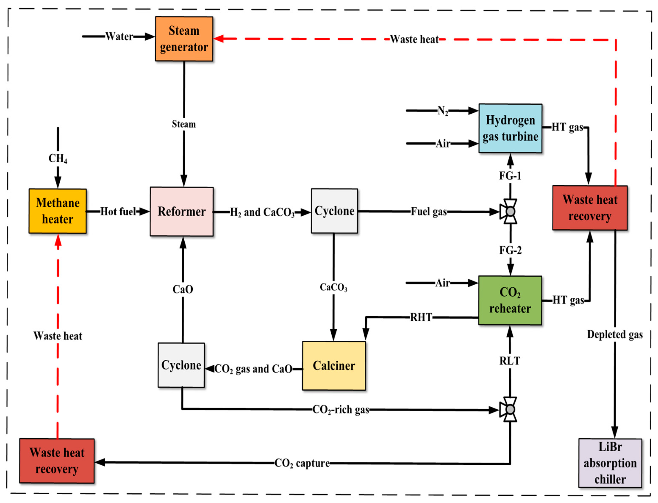
The energy penalty for CO2 capture is small. This is because calcium looping in the dual fluidized bed reactor is utilized, and the heat consumption for the calcination reaction and the heat release for the carbonation reaction can be balanced in theory.
(2)
No additional heat source is required. This is because a CO2 reheater is designed to heat the circulating CO2 flow via burning a small portion of the hydrogen-rich gas generated by the system.
(3)
Highly pure CO2 can be generated as a by-product. Circulating CO2 is used as a heat carrier for the calcination process; thus, the produced CO2 is nearly pure and can be commercially used for other purposes.

2. Modeling Methods

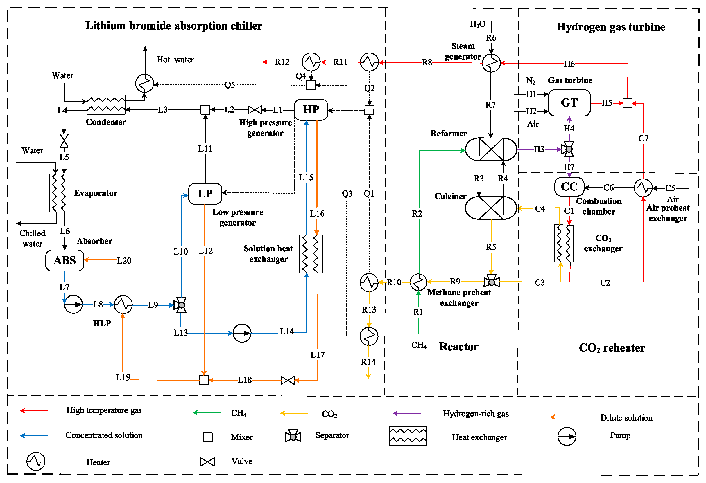
2.1. General Description

The proposed LC-CCHP system is depicted in Figure 1. It mainly consists of a hydrogen gas turbine, a dual fluidized bed reactor, a CO2 reheater, a lithium bromide absorption chiller, and some ancillary components. Obeying the energy cascaded utilization principle, the system key operation parameters are designed and listed in Table 1. The operation parameters of the chiller unit are given in Table 2.
Methane at 25 °C and 101.3 kPa is preheated in the methane heater (MEH) before entering the reactor. Meanwhile, water is converted into high-temperature steam in the steam generator (SG). Then, methane and steam are injected into the reformer and react with the bed material at 600 °C. The SE-SMR takes place in a fluidized bed reactor where the Ni-based catalyst serves as part of the bed material. With the catalytic effect, the reformation temperature and pressure can be low, while the reformation rate can be very high. To capture CO2 efficiently with CaO, the reaction temperature cannot be high according to the Le Chatelier principle. Based on the above consideration and the literature review [21], a temperature of 600 °C is proper and is selected as the reformation temperature. The sorbent (CaO)-to-catalyst (Ni) mass ratio is about 6.0 according to the literature [21]. After separation with the cyclone, the bed material flows into the calciner reactor, where CaCO3 is calcinated at a high temperature to regenerate CaO, which circulates back to the reformer. Part of the high-temperature CO2 is used as a byproduct after heat recovery, while the left provides heat required for the calciner.
The hydrogen-rich fuel gas from the cyclone is further split. A large portion of hydrogen-rich fuel gas (FG-1) flows into the gas turbine, while the left fuel gas (FG-2) flows into the CO2 reheater to produce high-temperature flue gas, which is used to supply heat to the calciner. The steam generator is heated by high-temperature gas from the hydrogen gas turbine and the CO2 reheater. Then, the waste heat is recovered by the lithium bromide absorption chiller.
To simplify the system modeling, a number of assumptions are considered:
(1)
The system operates under steady-state conditions.
(2)
The mole fractions of O2 and N2 in air are 21% and 79%.
(3)
The system piping and material loss is ignored in the conveying process.
(4)
Pressure is constant in the condenser and the evaporator.
(5)
The pump efficiency is assumed to be 0.85.
(6)
The isotropic and mechanical efficiencies of turbine are 0.85 and 0.95.

2.2. Exergy Analyses Methodology

The maximum reversible work carried out when the system thermodynamic states reach equilibrium with the ambient environment is called exergy [27,28]. It is a metric of the energy quality [29,30]. The exergy balance equation for the proposed system and the system sub-units can be calculated as follows [31]:
E X i n + W i n + E X i n Q = E X o u t + W o u t + E X o u t Q + L o s s
where E X i n and E X o u t refer to the inlet and outlet exergy flows of the material streams calculated by Equation (2) [32]; W i n and W o u t are the inlet and outlet exergy flow of the power or work streams; E X i n Q and E X o u t Q denote the inlet and outlet exergy flows of the heat streams; L o s s denotes the system’s exergy loss.
E X = E X p h + E X c h
where E X p h is the physical exergy; E X c h is the chemical exergy, and can be calculated as follows [33]:
E X c h = x i E X i c h + R T 0 x i ln x i
where x i represents the mole fraction of species i in the gas mixture; E X i c h indicates the standard chemical exergy of species i. The total power output and efficiencies can be calculated as follows:
W o u t = W G T W A C W P U M P 1 W P U M P 2
η e n = W O U T m · L H V f u e l
η t e n = W o u t + Q o u t + Q C o o l m · L H V f u e l
η e x = W o u t E X f u e l + E w a t e r i n + E a i r
η t e x = W o u t + E C o o l + Q o u t E X f u e l + E w a t e r i n + E a i r
where W G T , W A C , W P U M P 1 , and W P U M P 2 denote the power production from the gas turbine, power consumed by the air compressor, and the power consumed by the circulating pumps, respectively; η e n , η t e n , η e x , and η t e x mean the system power generation efficiency, system total efficiency, system power generation exergy efficiency, and system total exergy efficiency, respectively.

2.3. Economic Analyses Methodology

Besides the thermodynamic analyses, economic analyses are also essential for the assessment of the proposed LC-CCHP system. The total investment cost (TIC) and the operation and maintenance (O&M) cost are considered in the economic analyses. O&M consists of the variable O&M (VOM) and the fixed O&M (FOM) [34]. The economic model, assumptions, and calculation results are listed in Table 3, Table 4 and Table 5. To make sure that the prices can be added directly, all the costs have been adjusted to the 2024 level [35].
Parameter β in Table 3 is calculated by Equation (9).
β = { i [ 1 ( 1 + i ) N ] }
where i denotes the yearly interest rate; N denotes the system lifetime. The personal operation labor cost is considered to be USD 11,634.2 per year in China [35].

3. Modeling and Validation

A thermodynamic model is developed with Aspen Plus [26] to assess the performance of the system, and sensitivity analysis is carried out. The RK-SOAVE method is selected for the power generation unit [19]. Meanwhile, the ELECNRTL method is selected for the lithium bromide absorption chiller. Attention is focused on the SE-SMR reactor, the hydrogen gas turbine, and the lithium bromide absorption chiller. The overall system flow sheet is shown in Figure 2. To validate the system modeling methodology, the results from the SE-SMR unit, the hydrogen gas turbine, and the lithium bromide absorption chiller are compared against the results reported from the literature [21,41,43,44,45].

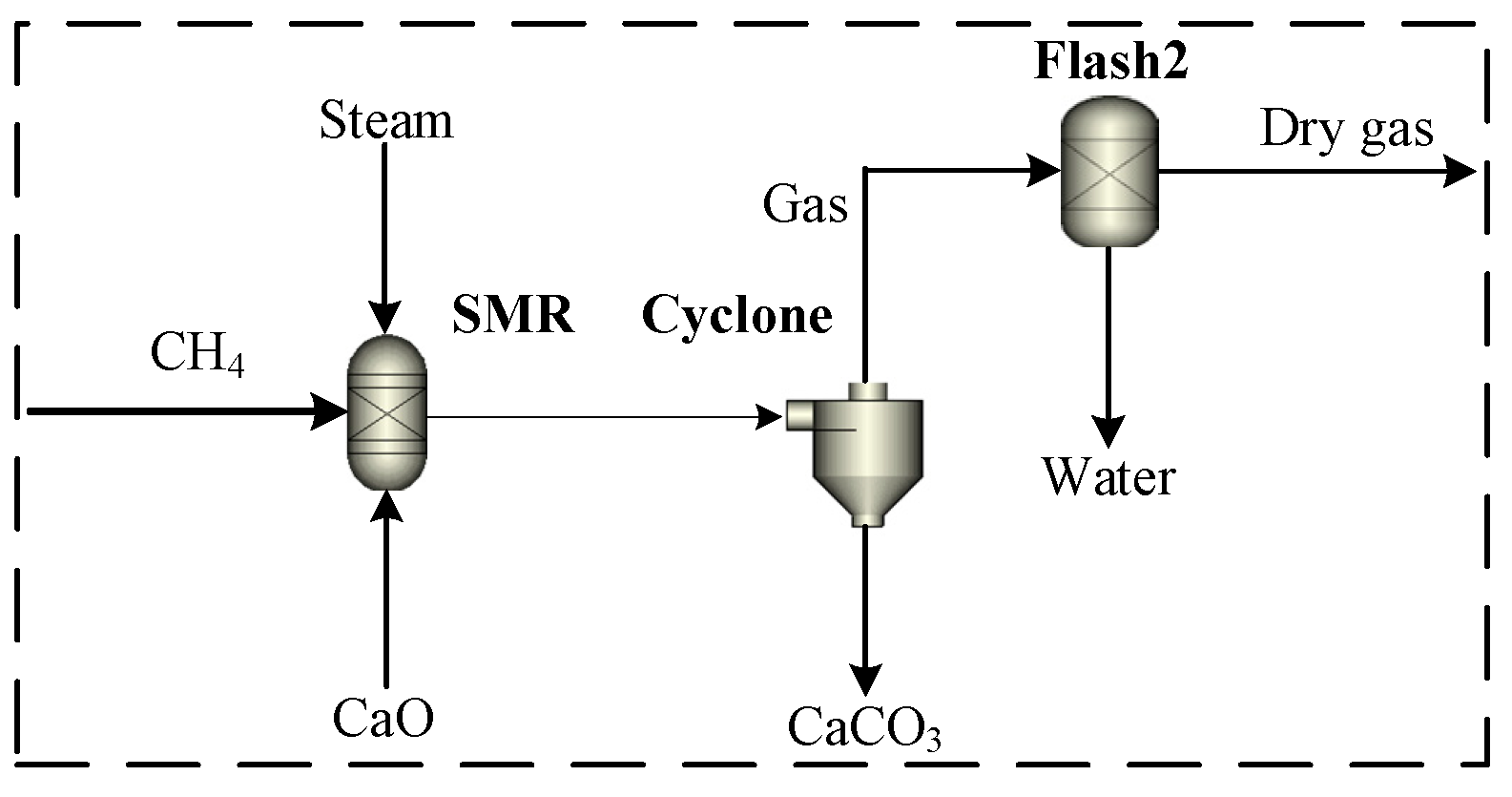
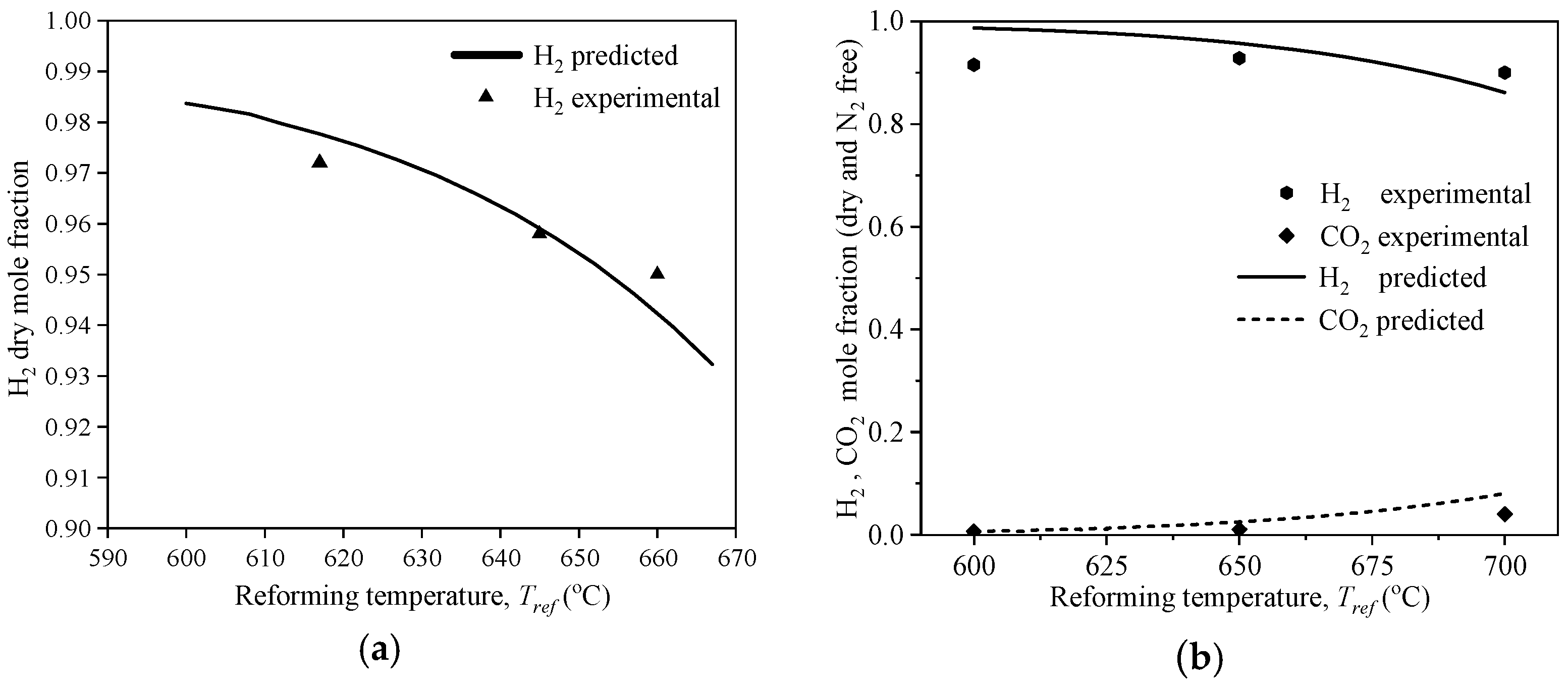
3.1. Sub-Model Validation for Sorption-Enhanced Steam Methane Reforming (SE-SMR)

The SE-SMR thermodynamic flow sheet is depicted in Figure 3. Methane and steam are injected into the reformer and reacted at 600 °C. The steam-to-carbon mole ratio is about 5.0. The SE-SMR model is validated against data reported in Ref. [43] and Ref. [21] at the same operating conditions as shown in Figure 4a,b. It can be seen that the predicted H2 and CO2 mole fractions in the dry syngas closely match the results of the experiment.

3.2. Sub-Model Validation for the Hydrogen Gas Turbine

The hydrogen gas turbine model flow sheet is depicted in Figure 5. High-pressure syngas and pure nitrogen are mixed and oxidized by air in the combustion chamber. The compressed air is partially injected into the burner as the oxidizer, while the left is cooled and injected into the turbine to adjust the medium temperature [44]. The main component of the high-pressure fuel gas is H2, with additional components including CH4, CO, CO2, and steam. The high-pressure fuel gas is mixed with N2 and burnt in the combustion chamber. The results predicted by the hydrogen gas turbine unit are compared against the reported data in Ref. [45], as listed in Table 6. The maximum deviation is 2.60%.

3.3. Sub-Model Validation for the Lithium Bromide Absorption Chiller

The lithium bromide absorption refrigeration unit in Aspen Plus is shown in Figure 6. It mainly consists of a high-pressure generator (GEN-HP) and a low-pressure generator (GEN-LP). The high-temperature flue gas (HT gas) and the CO2-rich flue gas are first cooled to 200 °C to provide heat for the high-pressure generator, in which the dilute lithium bromide solution at a higher pressure is vaporized. The vapor stream flows through the heat exchanger to supply heat to the low-pressure generator where a part of dilute lithium bromide solution is also vaporized. All of the steam sequentially passes through a condenser, a valve, and an evaporator to generate cold water. The concentrated lithium bromide solution then absorbs low-pressure vapor into the absorber to regenerate the dilute lithium bromide solution. Water at ambient temperature is used to cool the heat exchanger in the condenser and absorber unit. The results predicted from the lithium bromide absorption refrigeration unit are compared with the data reported in Refs. [46,47], as listed in Table 7. It can be seen that the maximum deviation is 2.99%.

3.4. Economic Model Validation

To make sure that the economic methodology is reliable and accurate, the economic predictions for the main components are compared against data reported in the literature [36,37,38,39], as shown in Table 8. It can be seen that the model predictions agree well with the literature data.

4. Results and Discussion

4.1. Sensitivity Analyses

The effects of five parameters including the SE-SMR reaction temperature ( T r e f ), steam-to-carbon mole ratio ( S / C ), calcium-to-carbon mass ratio ( R C C ), air equivalent ratio for GT ( R A E ), and the hydrogen fuel gas separation rate for the CO2 reheater ( S f g ) on the system performance are detected. The variation ranges of the system key operating parameters including T r e f , S / C , R C C , R A E , and S f g in the simulations are 580–665 °C, 2.0–6.0, 4–11, 1.0–1.8, and 0.267–0.300, respectively. The mole ratio of the captured CO2 to methane, R c m , is used as a criterion to assess the carbon capture capability of the system. It can be calculated as follows:
R c m = n ˙ C O 2 n ˙ C H 4
where n ˙ C H 4 is the mole flow rate of methane; n ˙ C O 2 is the mole flow rate of CO2 output from the entire system. The combustion temperature of GT was regulated by controlling the air equivalent ratio of GT. It is defined as RAE, and can be calculated as follows:
R A E = n ˙ a i r 2 · n ˙ C H 4 · ( 1 S f g ) / 0.21
where n ˙ C H 4 is the mole flow rate of methane; n ˙ a i r is the mole flow rate of air supplied to the gas turbine.
To assess the effects of key operating parameters on the system performance, sensitivity analysis is used. The baseline conditions are set as Tref = 600 °C, S/C = 5, RCC = 4.93, RAE = 1.20, and Sfg = 0.21, and their effects on the system energy efficiency (ηen), total energy efficiency (ηten), exergy efficiency (ηex), total exergy efficiency (ηtex), and carbon capture capability (Rcm) are shown in Figure 7. Note that ηen and ηex only consider the pure electric power of the system, while ηten and ηtex consider the waste heat recovery of the system besides the electric power.
In Figure 7a, it can be seen that the effect of T r e f on the system efficiency is slight, but the effect of T r e f on the carbon capture capability is obvious. η t e n and η t e x are around 90% and 60% in the given range of operating parameters. When T r e f is over 600 °C, R c m begin to drastically reduce with increments of T r e f . Figure 7b shows that η t e n , η t e x , η e x , and R c m descend as R c c ascends, while η e n ascends as R c c descends. Figure 7c shows that η t e n and η t e x decrease with increments of S / C , while η e n , η e x , and R c m present an opposite variation trend, because the SE-SMR reaction can be promoted with increments of S / C . Figure 7d indicates that T G T , η t e n , and η t e x all rise as R A E increases in the range of 1.0 to 1.3. However, in the range of 1.3 to 1.8, T G T decreases with increments of R A E . Figure 7e shows that η e n and η e x tend to drop as S f g increases because the amount of fuel gas supplied to the GT lessens. However, η t e n and η t e x tend to increase with the increases in S f g , indicating that the heat supply rises. From the above analyses, it can be concluded that the optimal operating parameters of the system are T r e f = 600   °C, S / C = 4.0 , R C C = 7.62 , R A E = 1.20 , and S f g = 0.27 . Under this condition, η t e n , η t e x , and R c m can be ~61%, ~68%, and ~96% of the system.
The exergy Sankey diagram of the proposed system is shown in Figure 8. The calculation results of the system’s exergy destruction analysis are shown in Table 9. The methane flow rate is assumed to be a fixed value of 10.8 kmol/h. The SE-SMR temperature is 600 °C. The circulating CO2 temperature is 1477 °C, and the flow rate is 72 kmol/h. The syngas reacts with air in the combustion chamber at 17 bar. It can be seen that the exergy loss of the calciner is 402 kW, which leads to an exergy efficiency of ~64.5%. The work output and the exergy destruction from the gas turbine are 796.8 kW and 492 kW, respectively, which leads to an exergy efficiency of ~78.7%. The maximum exergy destruction occurs at the gas turbine component, while the minimum exergy efficiency appears at the calciner component. The main cause of minimum exergy efficiency is the big temperature deviation between the calciner and circulating CO2. In order to improve the calciner’s efficiency, it is necessary to change the operating strategy of the calciner and the CO2 reheater.

4.2. Economic Predictions

With the validated economic model, the detailed TIC, VOC and FOC of the proposed system are calculated and listed in Table 10, Table 11 and Table 12. The total investment of the system is predicted to be USD 2.76 M, while the cost of electricity, cooling capacity, and heating is predicted to be 0.024 USD/kWh. As the byproduct, selling CO2 can result in an additional USD 0.0183 M per year. Assuming a constant electricity price of 0.05 USD/kWh, it is expected that the system annualized return on investment is about 12%, and the payback period is about 9 years.

4.3. Sub-Unit Optimization

The CO2 reheater depicted in Figure 9 is first optimized. It consists of a combustion chamber and two heat exchangers. The main control parameters are the flow rate of circulating CO2 and the combustion temperature. In this case, the combustion temperature is controlled by adjusting the air equivalent ratio, RAEC, since the amount of hydrogen-rich gas diverted to the CO2 reheater is fixed. This control parameter is calculated as follows:
R A E C = n ˙ a i r 2 · n ˙ C H 4 · S f g / 0.21
In addition, the circulating CO2 flow rate is controlled by the CO2 circulation ratio, Rcir, which is defined as follows:
R c i r = n ˙ c i r n ˙ c a p
where mcir is the mole flow rate of the circulating CO2-rich gas; mcap is the mole flow rate of the captured CO2-rich gas.
The different operating strategies of the CO2 reheater are shown in Table 13. The exergy analysis of model A is shown in Figure 10. Model A uses the default values of RAEC, Rcir, and Tcir which are 1.40, 7.03, and 1477 °C, respectively. Models B, C, D, and E use the improved values of RAEC, Rcir, and Tcir which are given in Table 10. As shown in Table 10, Mode E has the highest exergy efficiency of 74.4% and the lowest exergy destruction of 401 kW. It can be seen that despite the many adjustments made, the value of exergy destruction has a small variation, while the exergy efficiency has a large variation. The exergy efficiency (η) improves significantly as the CO2 recirculation flow rate increases and the reheating temperature decreases.
The lithium bromide absorption refrigeration process as shown in Figure 6 is also optimized. The heat loads of the absorber and condenser are defined as QABS and QCOND. The refrigeration unit efficiency is defined as ηr. The high-pressure generator/low-pressure generator flow rate ratio, RHL, can be calculated as follows:
R H L = m L P m H P + m L P
where mHP is the dilute solution mass flow rate of the high-pressure generator; mLP is the dilute solution mass flow rate of the low-pressure generator; (mHP + mLP) is the circulation dilute solution mass flow rate of the chiller.
The effect of R H L on the chiller’s performance is depicted in Figure 11. It can be seen that increasing R H L has slight effects on Q A B S and Q C O N D . The chiller’s performance is poor as R H L is 0.1. The energy efficiency ( η r ) and the coefficient of performance (COP) increase with the increase in R H L in the range of 0.10 to 0.60. As R H L is 0.57, η r and COP reach their highest points, leading to the best performance. When R H L is over 0.60, η r and COP begin to reduce vastly with the increase in R H L . The reason why the chiller’s performance decreases is that the effect of the low-pressure generator is greatly weakened, leading to a reduction in cooling capacity.

5. Conclusions

In this work, a new LC-CCHP system mainly consisting of a SE-SMR reactor, a calciner, a CO2 reheater, a hydrogen gas turbine, and a lithium bromide absorption chiller was proposed. Thermodynamic and economic models for the system were built and validated. Then, analyses of the main parameters were conducted, and the main findings are drawn as follows:
(1)
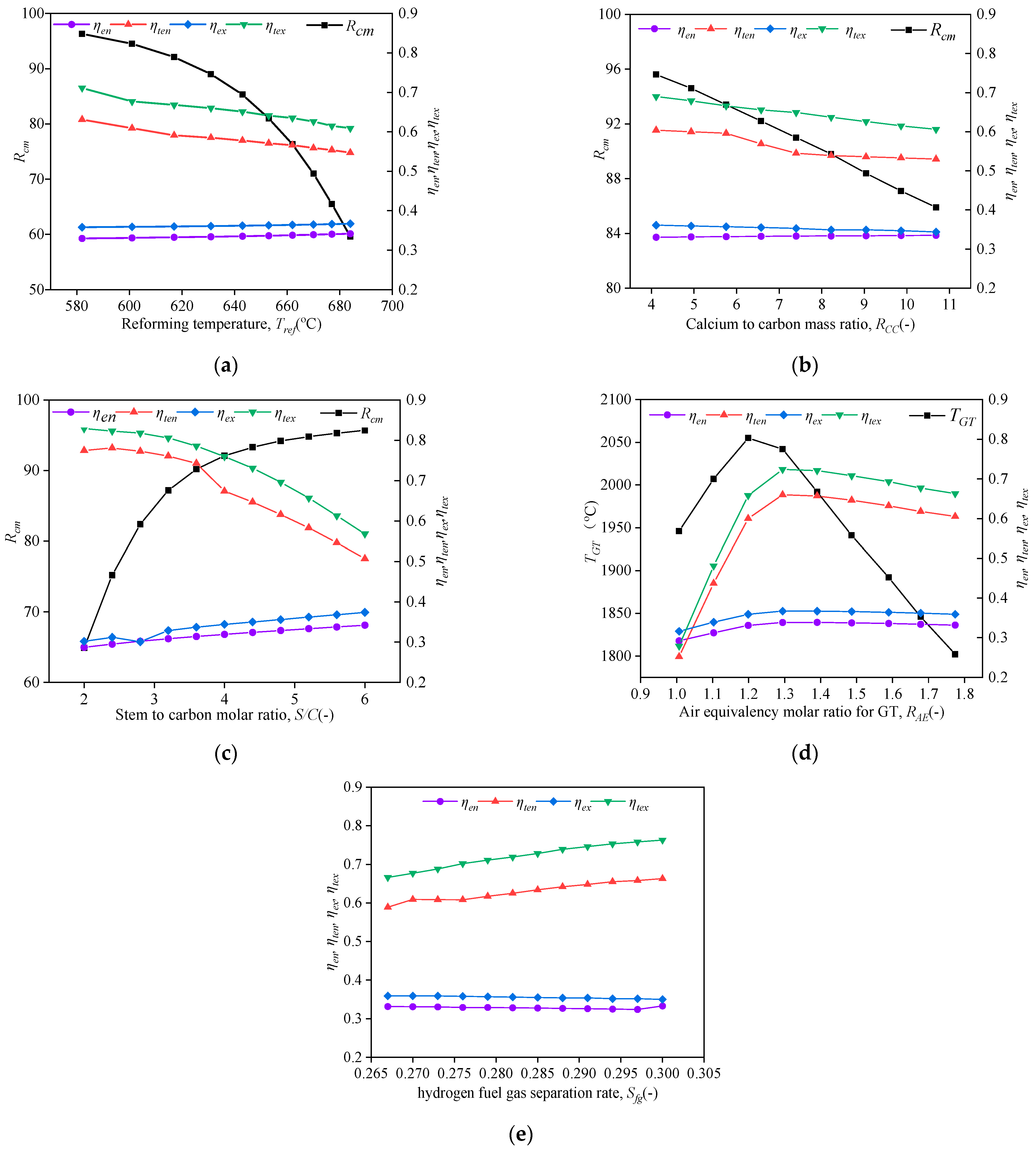
The whole system’s ηten, ηtex, and Rcm can reach ~61%, ~68%, and ~96%, respectively. The SE-SMR reaction temperature and steam-to-carbon mole ratio have major impacts on Rcm, which can be over 90% as Tref < 620 °C and S⁄C > 4.0.
(2)
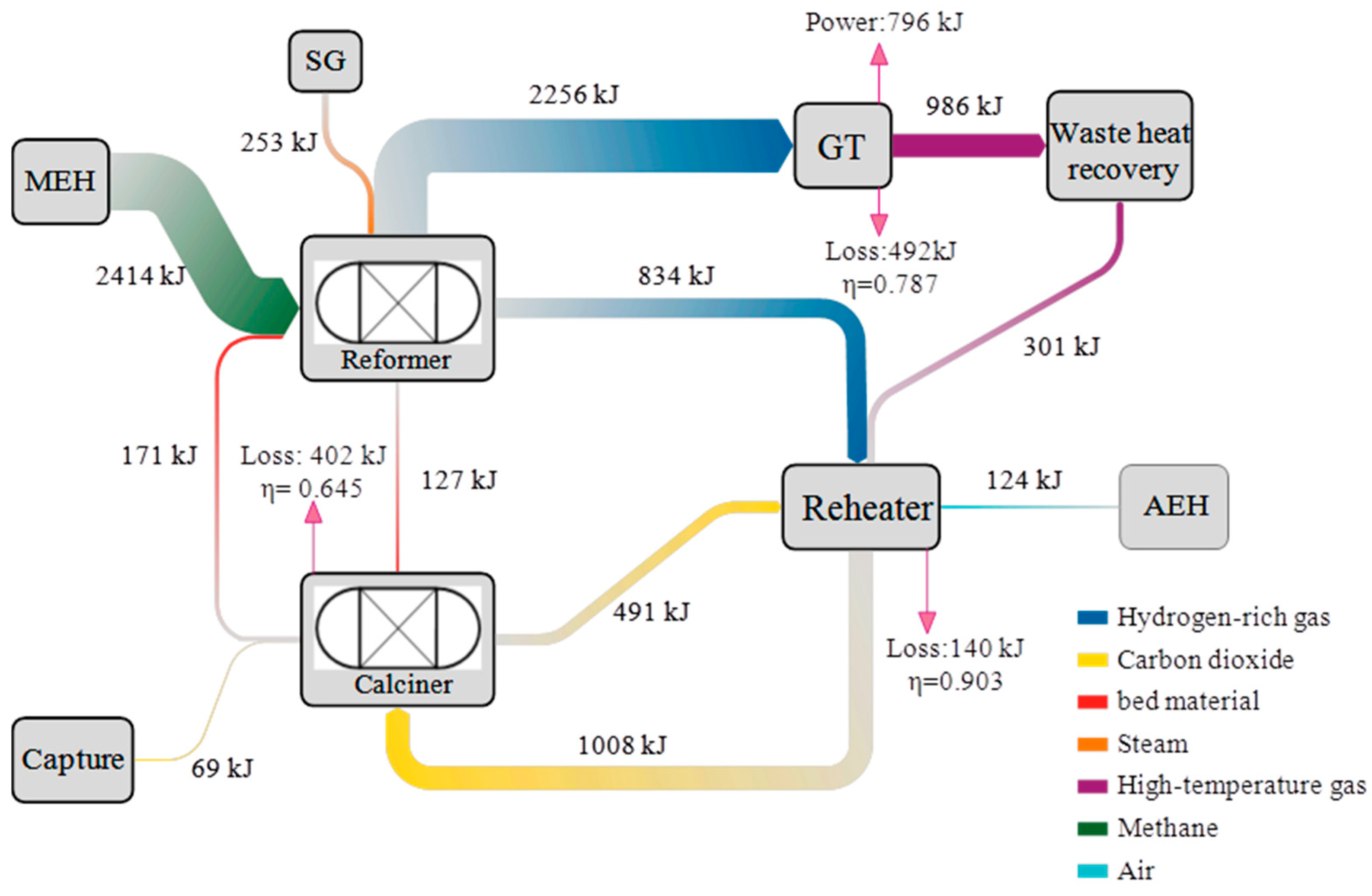
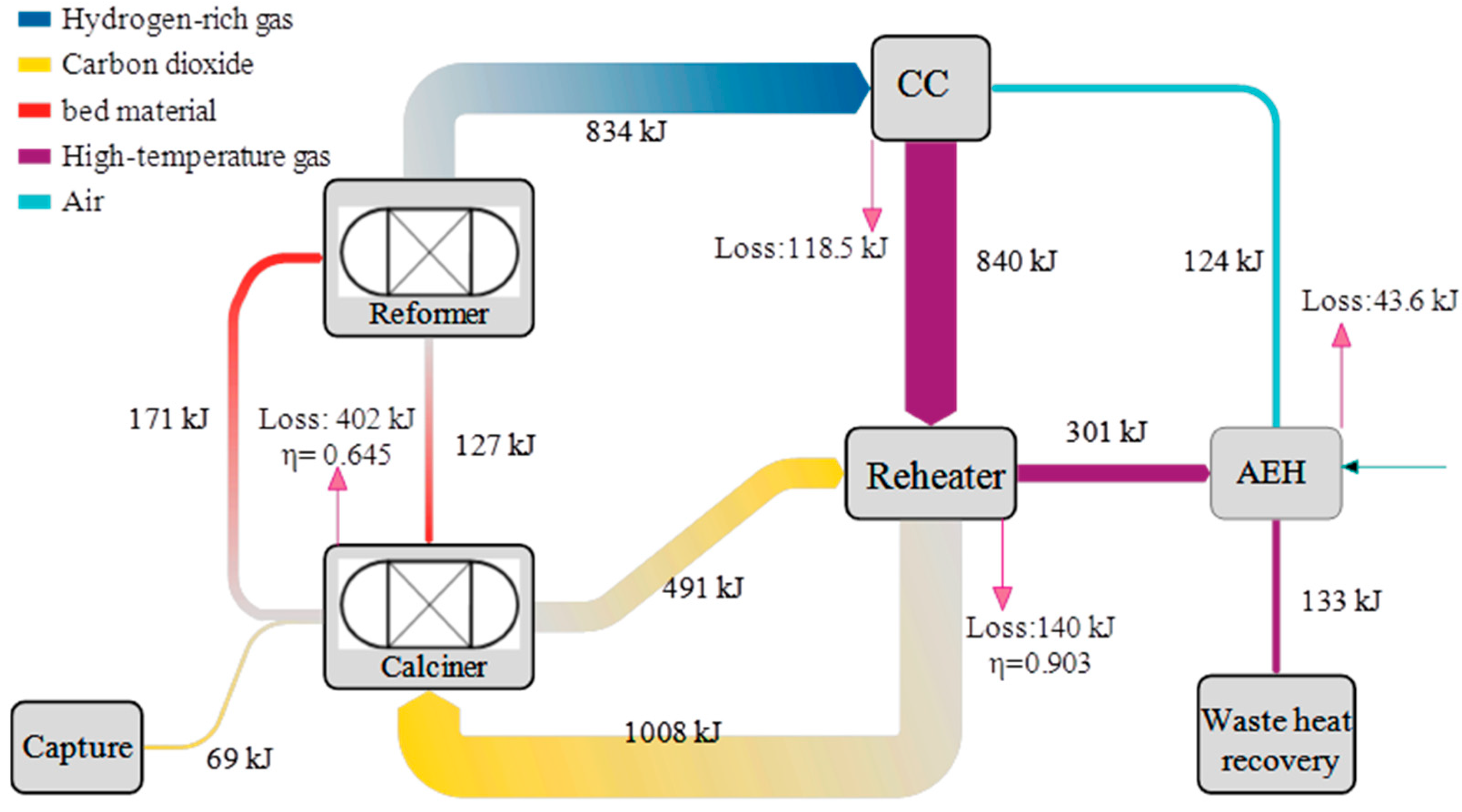
The minimum exergy efficiency is 64.5%, existing at the calciner component. Although the GT has the highest exergy destruction of 492 kW, it has a higher exergy efficiency of 78.7%. The main cause of minimum exergy efficiency is the large temperature difference between the calciner’s internal environment and the circulating CO2 flows. It can be improved by increasing the CO2 recirculation flow rate and decreasing the reheating temperature.
(3)
The chiller can keep a high value of ηr and COP with the increase in RHL in the range of 0.50 to 0.60. The maximum values of ηr and COP are 0.52 and 1.33, respectively, as RHL is 0.57.
(4)
The specific cost of the product is 0.024 USD/kWh. The system annualized return on investment is about 12%, and the payback period of investment is about 9 years.

Author Contributions

Conceptualization, L.Y. and C.G.; methodology, L.Y. and Z.J.; software, L.Y. and Z.J.; validation, L.Y., Z.J. and Y.L.; investigation, Z.J. and C.G.; writing—original draft preparation, Z.J. and C.G.; writing—review and editing, L.Y. and B.H.; visualization, Z.J. and Y.L.; supervision, L.Y.; funding acquisition, L.Y. and Y.L. All authors have read and agreed to the published version of the manuscript.

Funding

This research was funded by the State Key Laboratory of Intelligent Construction and Healthy Operation and Maintenance of Deep Underground Engineering, China University of Mining & Technology, Xuzhou, grant number SKLGDUEK2216, and the National Natural Science Foundation of China, grant number 12102456.

Institutional Review Board Statement

Not applicable.

Informed Consent Statement

Not applicable.

Data Availability Statement

The data presented in this study are available on request from the corresponding author. The data are not publicly available due to privacy.

Conflicts of Interest

The authors declare no conflicts of interest.

References

  1. Du, J.; Guo, J. Analysis of multi-cascade CCHP system with gas turbine bypass extraction air energy storage. Appl. Therm. Eng. 2023, 232, 121021. [Google Scholar] [CrossRef]
  2. Zhang, Y.; Lin, Y.; Lin, F.; Yang, K. Thermodynamic analysis of a novel combined cooling, heating, and power system consisting of wind energy and transcritical compressed CO2 energy storage. Energy Convers. Manag. 2022, 260, 119648. [Google Scholar] [CrossRef]
  3. Xia, Y.; Lei, H.; Wu, X.; Hu, G.; Pan, H.; Fang, B. Design of new test system for proton exchange membrane fuel cell. Energies 2023, 16, 833. [Google Scholar] [CrossRef]
  4. Feng, L.; Dai, X.; Mo, J.; Shi, L. Analysis of energy-matching performance and suitable users of conventional CCHP systems coupled with different energy storage systems. Energy Convers. Manag. 2019, 200, 112093. [Google Scholar] [CrossRef]
  5. Xu, Y.; Luo, X.; Tu, Z. 4E analysis of a SOFC-CCHP system with a LiBr absorption chiller. Energy Rep. 2022, 8, 5284–5295. [Google Scholar] [CrossRef]
  6. Gao, L.; Hwang, Y.; Cao, T. An overview of optimization technologies applied in combined cooling, heating and power systems. Renew. Sustain. Energy Rev. 2019, 114, 109344. [Google Scholar] [CrossRef]
  7. Wang, Q.; Duan, L.; Zheng, N.; Lu, Z. 4E Analysis of a novel combined cooling, heating and power system coupled with solar thermochemical process and energy storage. Energy 2023, 275, 127498. [Google Scholar] [CrossRef]
  8. Wang, X.; Duan, L.; Zheng, N. Thermodynamic analysis of a novel tri-generation system integrated with a solar energy storage and solid oxide fuel cell—Gas turbine. Appl. Therm. Eng. 2023, 219, 119648. [Google Scholar] [CrossRef]
  9. Ji, J.; Wen, W.; Xie, Y.; Xia, A.; Wang, W.; Xie, J.; Yin, Q.; Ma, M.; Huang, H.; Huang, X.; et al. Optimization and uncertainty analysis of Co-combustion ratios in a semi-isolated green energy combined cooling, heating, and power system (SIGE-CCHP). Energy 2024, 302, 131784. [Google Scholar] [CrossRef]
  10. Wang, L.; Bo, G.; Gao, R.; Ayadi, M.; Chammam, W.; Ooi, J.B.; Qin, M. Thermoeconomic assessment of an innovative combined cooling, heating, and power system based on biomass combustion, TCO2 cycle, absorption chiller, and desalination. Process Saf. Environ. Prot. 2024, 184, 151–169. [Google Scholar] [CrossRef]
  11. Jiang, R.; Yang, X. Performance analysis and application of a novel combined cooling, heating and power system integrated with multi-energy storage system. J. Energy Storage 2024, 86, 111276. [Google Scholar] [CrossRef]
  12. Lucarelli, G.; Genovese, M.; Florio, G.; Fragiacomo, P. 3E (energy, economic, environmental) multi-objective optimization of CCHP industrial plant: Investigation of the optimal technology and the optimal operating strategy. Energy 2023, 278, 127837. [Google Scholar] [CrossRef]
  13. Liu, Y.; Han, J.; You, H. Exergoeconomic analysis and multi-objective optimization of a CCHP system based on SOFC/GT and transcritical CO2 power/refrigeration cycles. Appl. Therm. Eng. 2023, 230, 120686. [Google Scholar] [CrossRef]
  14. Eddine, G.D.; Meriem, A.; Khaled, L.; Umberto, D.; Mohand, T. Multi-objective optimization of CCHP system with hybrid chiller under new electric load following operation strategy. Energy 2021, 219, 119574. [Google Scholar]
  15. Mahmood, C.; Reza, N.; Majid, H.S.; Rahmat, M.; Seyedesmail, H. Energy, exergy, economic, and environmental (4E) analyses and optimization of a CCHP system with steam turbine. Energy Sci. Eng. 2021, 9, 867–915. [Google Scholar]
  16. Song, Z.; Liu, T.; Liu, Y.; Jiang, X.; Lin, Q. Study on the optimization and sensitivity analysis of CCHP systems for industrial park facilities. Int. J. Electr. Power Energy Syst. 2020, 120, 105984. [Google Scholar] [CrossRef]
  17. Fang, B.; Daniel, L.; Bonakdarpour, A.; Wilkinson, D. Upgrading the state-of-the-art electrocatalysts for PEM fuel cell applications. Adv. Mater. Interfaces 2022, 9, 2200349. [Google Scholar] [CrossRef]
  18. Fang, B.; Daniel, L.; Bonakdarpour, A.; Govindarajan, R.; Sharman, J.; Wilkinson, D. Dense Pt nanowire electrocatalysts for improved fuel cell performance using a graphitic carbon nitride-decorated hierarchical nanocarbon support. Small 2021, 17, 2102288. [Google Scholar] [CrossRef] [PubMed]
  19. Darabadi, Z.A.A.; Mortaza, Y.; Hossein, N.; Farzad, M. Low-carbon hydrogen, power and heat production based on steam methane reforming and chemical looping combustion. Energy Convers. Manag. 2023, 279, 116752. [Google Scholar]
  20. Di Giuliano, A.; Gallucci, K. Sorption enhanced steam methane reforming based on nickel and calcium looping: A review. Chem. Eng. Process.-Process Intensif. 2018, 130, 240–252. [Google Scholar] [CrossRef]
  21. García-Lario, A.L.; Aznar, M.; Martinez, I.; Grasa, G.S.; Murillo, R. Experimental study of the application of a NiO/NiAl2O4 catalyst and a CaO-based synthetic sorbent on the sorption enhanced reforming process. Int. J. Hydrogen Energy 2015, 40, 219–232. [Google Scholar] [CrossRef]
  22. Meyer, J.; Mastin, J.; Pinilla, C.S. Sustainable Hydrogen Production from Biogas Using Sorption-Enhanced Reforming. Energy Procedia 2014, 63, 6800–6814. [Google Scholar] [CrossRef]
  23. Yan, L.; Li, K.; Sui, H.; He, B.; Geng, C.; Fang, B. Simulation of Sorption-Enhanced Steam Methane Reforming over Ni-Based Catalyst in a Pressurized Dual Fluidized Bed Reactor. Inorganics 2023, 11, 107. [Google Scholar] [CrossRef]
  24. Yan, Y.; Manovic, V.; Anthony, E.J.; Clough, P.T. Techno-economic analysis of low-carbon hydrogen production by sorption enhanced steam methane reforming (SE-SMR) processes. Energy Convers. Manag. 2020, 226, 113530. [Google Scholar] [CrossRef]
  25. Yan, Y.; Thanganadar, D.; Clough, P.T.; Mukherjee, S.; Patchigolla, K.; Manovic, V.; Anthony, E.J. Process simulations of blue hydrogen production by upgraded sorption enhanced steam methane reforming (SE-SMR) processes. Energy Convers. Manag. 2020, 222, 113144. [Google Scholar] [CrossRef]
  26. Aspen Technology, Inc. Aspen Plus User Models; Aspen Technology, Inc.: Bedford, MA, USA, 2015. [Google Scholar]
  27. Modi, B.; Mudgal, A.; Patel, B. Energy and Exergy Investigation of Small Capacity Single Effect Lithium Bromide Absorption Refrigeration System. Energy Procedia 2017, 109, 203–210. [Google Scholar] [CrossRef]
  28. Zare, A.D.; Saray, R.K.; Mirmasoumi, S.; Bahlouli, K. Optimization strategies for mixing ratio of biogas and natural gas co-firing in a cogeneration of heat and power cycle. Energy 2019, 181, 635–644. [Google Scholar] [CrossRef]
  29. Darabadi, Z.A.A.; Mortaza, Y.; Farzad, M.; Hossein, N.; Umberto, D. Thermodynamic and exergoeconomic analysis of a multi- generation gas-to-X system based on fuel-rich combustion to produce power, hydrogen, steam and heat. Sustain. Cities. Soc. 2019, 86, 104139. [Google Scholar]
  30. Eveloy, V.; Karunkeyoon, W.; Rodgers, P.; Alili, A.A. Energy, exergy and economic analysis of an integrated solid oxide fuel cell—Gas turbine—Organic Rankine power generation system. Int. J. Hydrogen Energy 2016, 41, 13843. [Google Scholar] [CrossRef]
  31. Mehrpooya, M.; Sayyad, S.; Zonouz, M.J. Energy, exergy and sensitivity analyses of a hybrid combined cooling, heating and power (CCHP) plant with molten carbonate fuel cell (MCFC) and Stirling engine. J. Clean. Prod. 2017, 148, 283–294. [Google Scholar] [CrossRef]
  32. Yumrutas, R.; Kunduz, M.; Kanoğlu, M. Exergy analysis of vapor compression refrigeration systems. Int. J. Exergy 2002, 2, 266. [Google Scholar] [CrossRef]
  33. Bereche, R.P.; Gonzales, R.; Nebra, S.A. Exergy calculation of lithium bromide–water solution and its application in the exergetic evaluation of absorption refrigeration systems LiBr-H2O. Int. J. Energy Res. 2012, 36, 166–181. [Google Scholar] [CrossRef]
  34. Yan, L.B.; Cao, Y.; He, B.S. Energy, exergy and economic analyses of a novel biomass fueled power plant with carbon capture and sequestration. Sci. Total Environ. 2019, 690, 812–820. [Google Scholar] [CrossRef] [PubMed]
  35. Yan, L.B.; Cao, Y.; Wang, Z.L.; He, B.S. On a novel carbon-negative IGCC system with cascade CO2 combined cycle. Energy Convers. Manag. 2020, 221, 113202. [Google Scholar] [CrossRef]
  36. Wu, Z.; Zhu, P.; Yao, J.; Zhang, S.; Ren, J.; Yang, F.; Zhang, Z. Combined biomass gasification, SOFC, IC engine, and waste heat recovery system for power and heat generation: Energy, exergy, exergoeconomic, environmental (4E) evaluations. Appl. Energy 2020, 279, 115794. [Google Scholar] [CrossRef]
  37. Mohammad, O.; Faryar, S.; Mojtaba, O. A solar-biomass system associated with CO2 capture, power generation and waste heat recovery for syngas production from rice straw and microalgae: Technological, energy, exergy, exergoeconomic and environmental assessments. Appl. Energy 2023, 340, 120999. [Google Scholar]
  38. Moghimi, M.; Emadi, M.; Ahmadi, P.; Moghadasi, H. 4E analysis and multi-objective optimization of a CCHP cycle based on gas turbine and ejector refrigeration. Appl. Therm. Eng. 2018, 141, 516–530. [Google Scholar] [CrossRef]
  39. You, H.; Han, J.; Liu, Y.; Chen, C.; Ge, Y. 4E analysis and multi-objective optimization of a micro poly-generation system based on SOFC/MGT/MED and organic steam ejector refrigerator. Energy 2020, 206, 118122. [Google Scholar] [CrossRef]
  40. Yuan, Z.; Liang, T.; Yang, K. An integrated energy storage system consisting of Compressed Carbon dioxide energy storage and Organic Rankine Cycle: Exergoeconomic evaluation and multi-objective optimization. Energy 2022, 247, 123566. [Google Scholar]
  41. Wang, S.; Fu, Z. Thermodynamic and economic analysis of solar assisted CCHP-ORC system with DME as fuel. Energy Convers. Manag. 2019, 186, 535–545. [Google Scholar] [CrossRef]
  42. Cormos, C.C.; Vatopoulos, K.; Tzimas, E. Assessment of the consumption of water and construction materials in state-of-the-art fossil fuel power generation technologies involving CO2 capture. Energy 2013, 51, 37–49. [Google Scholar] [CrossRef]
  43. Di Carlo, A.; Bocci, E.; Zuccari, F.; Dell’Era, A. Numerical Investigation of Sorption Enhanced Steam Methane Reforming Process Using Computational Fluid Dynamics Eulerian−Eulerian Code. Ind. Eng. Chem. Res. 2010, 49, 1561–1576. [Google Scholar] [CrossRef]
  44. Abanades, J.C. The maximum capture efficiency of CO2 using a carbonation/calcination cycle of CaO/CaCO3. Chem. Eng. J. 2017, 90, 303–306. [Google Scholar] [CrossRef]
  45. Lan, W.; Chen, G.; Zhu, X.; Wang, X.; Liu, C.; Xu, B. Biomass gasification-gas turbine combustion for power generation system model based on ASPEN PLUS. Sci. Total Environ. 2018, 628, 1278–1286. [Google Scholar] [CrossRef] [PubMed]
  46. Herold, K.E.; Radermacher, R.; Klein, S.A. Absorption Chillers and Heat Pumps; CRC Press: Boca Raton, FL, USA, 2016. [Google Scholar]
  47. Xu, L.; Huang, Y.; Li, G. Simulation and analysis of dual-effect absorption refrigeration units based on Aspen Plus. Build. Therm. Vent. Air Cond. 2021, 40, 6. [Google Scholar]
Figure 1. Schematic of the proposed LC-CCHP system.
Atmosphere 15 00836 g001
Figure 2. The overall system module simulation in Aspen Plus.
Atmosphere 15 00836 g002
Figure 3. Sorption-enhanced steam methane reforming thermodynamic model.
Atmosphere 15 00836 g003
Figure 4. Comparison of the SE-SMR model prediction with experimental data [21,43]. (a) Comparison of predicted and experimental H2 dry mole fraction; (b) comparison of predicted and experimental H2 and CO2 dry and N2 free mole fractions.
Atmosphere 15 00836 g004
Figure 5. Hydrogen gas turbine thermodynamic model.
Atmosphere 15 00836 g005
Figure 6. Lithium bromide absorption refrigeration thermodynamic model.
Atmosphere 15 00836 g006
Figure 7. Effects of the key operating parameters on the system performance. (a) Effects of Tref on the system performance; (b) Effects of RCC on the system performance; (c) Effects of S/C on the system performance; (d) Effects of RAE on the system performance; (e) Effects of Sfg on the system performance.
Atmosphere 15 00836 g007
Figure 8. Exergy Sankey flows of the proposed system.
Atmosphere 15 00836 g008
Figure 9. Sub-model of the CO2 reactor.
Atmosphere 15 00836 g009
Figure 10. CO2 reheater exergy analysis diagram.
Atmosphere 15 00836 g010
Figure 11. Effect of mass flow rate ratio of GEN-LP and GEN-HP on the unit performance.
Atmosphere 15 00836 g011
Table 1. Main operation parameters of the simulation.
Design ParametersValue
Ambient pressure (kPa)101.3
Ambient temperature (°C)25
Steam-to-carbon mole ratio (−)2–6
Gas turbine back pressure (kPa)107
Isentropic efficiency of compressor (%)0.85
Isentropic efficiency of pump (%)0.9
Lower heating value of CH4 (kJ/kg)49,303
Lower heating value of H2 (kJ/kg)11,900
AC pressure ratio (−)17
Maximum effectiveness of heat exchangers (%)95
The life time (year)30
Annual plant operating hours (h)8000
Table 2. Operating parameters of the refrigeration unit components.
Design ParametersValue
GEN-HP operation pressure (kPa)66
GEN-LP operation pressure (kPa)4
Concentration of concentrated solution (%)60
Concentration of dilute solution (%)55
Pressure of condenser (kPa)4
Pressure of evaporator (kPa)1
Pressure of absorber (kPa)1
High-pressure stage solution flow rate (kg/s)0.51
Low-pressure stage solution flow rate (kg/s)0.70
Mass flow rate ratio of GEN-LP and GEN-HP (−)0.578
Table 3. Economic analysis method and results of the thermodynamic system [34,35].
TIC CalculationMethods
Equipment cost CESee Table 4
Utilities and offsite units installed cost (A)25% of main equipment cost ( C E )
Installed cost (IC) I C = ( C E ) + A
Owners’ cost and contingency (B)15% of IC
Land purchase, permitting, surveying, etc. (C)5% of IC
Total investment costs (TIC) T I C = I C + B + C
O&M calculationMethods
VOM costs (D)SUM (1:8)
1 Raw material (excluding fuel)See Table 5
2 Fuel costSee Table 5
3 Maintenance3% of TIC
4 Operating supplies1% of TIC
5 Patents and royalties3% of O&M costs
6 Operating labor4 laborers [34]
7 Supervision/clerical10% of operating labor
8 Laboratory charges10% of operating labor
Fixed charges (F1)SUM (9:11)
9 Capital chargeβ*TIC
10 Local taxes2% of TIC
11 Insurance1% of TIC
Plant overhead (F2)5% of O&M costs
General expenses (F3)SUM (12:14)
12 Marketing, sales, distribution2% of O&M costs
13 Administrative2% of O&M costs
14 R&D5% of O&M costs
FOM costs ( F = F 1 + F 2 + F 3 )-
CO2 emission penalty (G)CO2 emission in flue gases * ETS CO2 price
O&M costsD + F + G
Table 4. The LC-CCHP system’s component equipment cost.
ComponentsEquipment Cost EquationsYearSource
Reformer C R e f = 130 ( A R e f 0.093 ) 0.78 + 3240 ( V R e f ) 0.4 + 21 , 280.5 V R e f 2014[36]
Calciner C C a l = 590 , 000 · ( m C a C O 3 59 , 875 ) 0.67 2015[37]
GT C G T = W G T [ 1318.5 98.328 ln ( W G T ) ] 2020[38,39]
AEH C A E H = 2681 · A A E H 0.59 2014[40,41]
MEH C M E H = 2681 · A M E H 0.59 2014[7,40]
CBH C C B H = 2681 · A C B H 0.59 2014[7,40]
SG C S G = 2681 · A S G 0.59 2014[7,40]
Chiller C C o o l = Q C o o l · ( 482 · Q C o o l 0.07273 159.7 ) 2019[41]
Heating C H e a t = 2681 · A H e a t 0.59 2014[7,40]
Table 5. Basic economic assumptions for calculation.
ItemsAssumptionsSource
CaO cost5.534 USD/t[37]
CH4 cost9.51 USD/GJ[29]
Ni cost21,800 USD/t-
LiBr cost690.7 USD/t-
Cooling water price0.014 USD/t[42]
Labor employee cost11,634.2 USD/year[34]
ETS CO2 price21.59 USD/t[35]
CO2 price6.11 USD/t[35]
Economical plant life20 years[13]
Table 6. Comparisons between the GT model predictions and design values [45].
ParametersDesign ValueModel PredictionDeviation %
Compression ratio1717-
Expansion ratio1717-
Net electric power (MW)270274.51.70
Gas turbine inlet temperature (°C)14001409.50.70
Gas turbine outlet temperature (°C)586571.02.60
Air mass flow rate (kg/s)651649.50.20
Net power efficiency (%)38.238.50.80
Table 7. Comparisons between the refrigeration model predictions and design values [46,47].
ParametersLiterature DataSimulation ResultsDeviation %
GENHP load (kW)265.4266−0.23
GENHP to GENLP energy (kW)201.9199.51.19
Condenser load (kW)183.6180.71.58
Absorber load (kW)442.5435.21.65
Evaporator load (kW)360.6349.82.99
Table 8. Economic validations of main components.
ComponentUnitLiterature DataEconomic DataDeviation %Source
ReformerUSD/kmol0.1720.1644.70[36]
CalcinerUSD/t1.6631.5854.90[37]
Gas turbineUSD/h3.5273.6242.80[38,39]
Table 9. The exergy destruction of the main components.
ComponentsExergy Destruction (kW)η (%)Proportion (%)
Calciner40264.538.9
GT49278.747.6
Reheater14090.313.5
Table 10. Economic analysis method and results of the thermodynamic system [34,35].
TIC CalculationValue (kUSD)
Equipment cost CE1023.3
Utilities and offsite units installed cost (A)255.8
Installed cost (IC)1279.1
Owners’ cost and contingency (B)191.9
Land purchase, permitting, surveying, etc. (C)63.9
Total investment costs (TIC)1534.9
O&M calculationValue (kUSD)
VOM costs (D)900.7
1 Raw material (excluding fuel)83.8
2 Fuel cost662.2
3 Maintenance46.0
4 Operating supplies15.3
5 Patents and royalties37.7
6 Operating labor46.5
7 Supervision/clerical4.6
8 Laboratory charges4.6
Fixed charges (F1)144.2
9 Capital charge98.2
10 Local taxes30.7
11 Insurance15.3
Plant overhead (F2)60.7
General expenses (F3)109.3
12 Marketing, sales, distribution24.3
13 Administrative24.3
14 R&D60.7
FOM costs ( F = F 1 + F 2 + F 3 )314.2
CO2 emission penalty (G)3.8
O&M costs1218.7
Table 11. The LC-CCHP system’s component equipment cost.
ComponentsC0 (kUSD)
Reformer284.2
Calciner46.2
GT579.8
AEH3.5
MEH1.8
CBH7.8
SG10.3
Chiller74.8
Heating14.9
Table 12. Basic economic assumptions for calculation.
ItemsCost (kUSD)
CaO cost37.8
CH4 cost662.2
Ni cost24.8
LiBr cost16.3
Cooling water price4.9
Labor employee cost290.8
ETS CO2 price3.8
CO2 price22.1
Table 13. Different operation modes of CO2 reheater and exergy indications.
ModelRAECRcirTcir (°C)η (%)Exergy Destruction (kW)
A1.407.03147764.4404
B1.408.72132765.9409
C1.9412.3122772.5403
D1.948.81137767.6410
E1.9414.0117774.4401
Disclaimer/Publisher’s Note: The statements, opinions and data contained in all publications are solely those of the individual author(s) and contributor(s) and not of MDPI and/or the editor(s). MDPI and/or the editor(s) disclaim responsibility for any injury to people or property resulting from any ideas, methods, instructions or products referred to in the content.

