Article

Study on Excavation Response of Deep Foundation Pit Supported by SMW Piles Combined with Internal Support in Soft Soil Area

1
College of Civil Engineering, Huaqiao University, Xiamen 361021, China
2
Fujian Provincial Institute of Architectural Design and Research Co., Ltd., Fuzhou 350108, China
3
Key Laboratory of Disaster Mitigation in Civil Engineering of Gansu Province, Lanzhou University of Technology, Lanzhou 730050, China
4
Western Center of Disaster Mitigation in Civil Engineering, Ministry of Education, Lanzhou University of Technology, Lanzhou 730050, China
*
Authors to whom correspondence should be addressed.
Water 2023, 15(19), 3430; https://doi.org/10.3390/w15193430
Submission received: 31 August 2023 / Revised: 25 September 2023 / Accepted: 28 September 2023 / Published: 29 September 2023
(This article belongs to the Special Issue Risk Management Technologies for Deep Excavations in Water-Rich Areas)

Abstract

:
Based on a foundation pit project in Fuzhou, China, the influence of foundation pit excavation on the supporting structure and surrounding environment in a soft-soil area is studied. This study was based on actual monitoring data and investigated the variations in the supporting structure, surrounding constructions, and groundwater levels during excavation. The analysis of the monitoring data demonstrates the presence of pronounced ‘spatial effects’ and ‘temporal effects’ on the deformation of the support structure and surrounding structures. The deformation of the support structure and surrounding structures exhibits distinct spatial distribution characteristics at different locations along the excavation pit wall. Typically, more significant deformations are observed in the middle section of the pit wall, while deformations decrease as the distance from the pit corner decreases. The support structure’s and surrounding structures’ deformation characteristics vary during different construction stages. During the excavation phase, the rate of deformation increase in the support structure and surrounding structures is notably higher. In contrast, during the construction of the underground basement floor and the backfilling phase of the excavation pit, the rate of deformation increase in the support structure and surrounding structures is relatively lower. Throughout the entire construction period of the excavation pit, the groundwater level in the vicinity of the pit exhibits a fluctuating trend. Apart from the influence of rainfall, the overall variation in groundwater level is minimal, indicating the effective water-sealing performance of the combined Soil-Mixing Wall (SMW) support structure within the circular enclosure.

1. Introduction

The continuous development of high-rise buildings and underground space construction has led to many deep foundation pit projects. These pits exhibit notable features, such as a wide excavation area, great excavation depth, and a complex surrounding environment. Due to these characteristics, such projects present unique and significant challenges for foundation pit construction and design. These challenges make foundation pit support structures and surrounding structures susceptible to significant deformation or settlement. To ensure the safety of foundation pits and surrounding structures during excavation in soft-soil areas and reduce unnecessary economic losses, it is essential to conduct research on the excavation response and analyze the stress and deformation of the pit and surrounding structures during excavation.
Many scholars have carried out research on the stress and deformation of excavation engineering. Ou [1] conducted a study on the characteristics of ground settlement during the excavation process of foundation pits by analyzing monitoring data from multiple engineering examples of excavation projects. Wong et al. [2] derived empirical formulas for the deformation of enclosure structures and ground settlement by analyzing monitoring data from multiple excavation engineering projects in Singapore. Through analysis of the support issues in deep foundation pit engineering in soft-soil areas in China, Huang et al. [3] identified vital problems in foundation pit support, including analysis methods, construction techniques, deformation monitoring, and the construction environment. Ye et al. [4] monitored the horizontal and vertical displacement of pile tops, surface settlement, axial force of steel supports, and groundwater level during the construction process of a subway station excavation project. They systematically analyzed the stress and deformation characteristics of the support structure during the excavation process and comprehensively summarized the stress and deformation characteristics of the internal support structure. Fook et al. [5] studied the excavation response of multi-level support structures through numerical simulation and field measurement data and analyzed the spatial effect of the internal support structure of the excavation support. In studying internal support structures for concrete rings, Cheng et al. [6] investigated ultra-deep foundation pits supported by circular internal supports using an engineering case study. They conducted a systematic analysis of the stress conditions of the circular internal support structure and identified critical areas of attention for the engineering application of circular internal supports from both construction and design perspectives. Li et al. [7] analyzed an asymmetric circular internal support structure and proposed design concepts and analytical methods for asymmetric circular lining-supported excavations based on engineering monitoring data. Liu et al. [8] studied the excavation response of a super-large irregular foundation pit in soft-soil areas. By analyzing monitoring data, they discovered that the construction period and pit size have varying impacts on the internal support structure of the concrete and the surrounding environment. In general, more extended construction periods and larger pit sizes result in a more significant deformation of the pit and surrounding structures. Several researchers [9,10,11,12,13,14,15,16,17] have investigated the stress and deformation of support structures during the excavation of foundation pits. However, these studies mainly focused on small- to medium-sized foundation pits and were conducted for foundation pits with better soil conditions. There is a dearth of research on the excavation response of foundation pits in soft-soil areas. Due to their remarkable ability to provide effective waterproofing and structural support, SMW support structures have found extensive application in areas with high water levels. Chen and Cui [18] monitored a deep excavation supported by a combination of SMW and anchor cables as the support structure.
Based on field monitoring data, Feng et al. [19] used the numerical simulation method to study the deformation law of the retaining structure and surrounding soil during the excavation of a soft-soil foundation pit. Chen et al. [20] observed the deformation characteristics of deep foundation pits and the interaction between adjacent foundation pits via a monitoring system. Ki et al. [21] measured the parameters of a soil hardening model (HSM) of soft clay through an experimental method, which provided a method for the study of soil constitutive models in soft-soil areas. Based on the stress and deformation characteristics of deep foundation pit excavations in soft-soil areas, Panchal et al. [22] studied the construction technology and equipment for deep foundation pit excavation in soft-soil areas. An analysis of the monitoring data on the anchor cables’ internal forces, the pile tops’ horizontal displacement, and the groundwater levels revealed a close correlation between the maximum horizontal displacement of the support structure and the excavation depth and time. Furthermore, fluctuations in groundwater levels significantly influenced the operational behavior of the SMW and anchor cable combined support structure. Ding et al. [23] employed a novel monitoring technology to achieve real-time monitoring of the stress and deformation of SMW support structures under complex conditions. Real-time data analysis enabled the identification of stress and deformation characteristics of SMWs. Xian et al. [24] conducted a study on the application of SMW support structures in sandy areas and investigated the mechanical behavior of SMW support structures during excavation and backfilling processes based on actual engineering cases, providing a reference for the design and construction of SMW support structures in sandy areas. Chen et al. [25] conducted model experiments to measure the horizontal displacement of pile tops in SMW support structures during excavation. Through the analysis of experimental observations, they revealed the deformation and failure characteristics of excavation pits supported by SMW in soft-soil areas. Research has also been carried out on the influence of foundation pits on adjacent structures. Finno et al. [26] and Son et al. [27] put forward the damage standard and judgment method of buildings affected by foundation pit excavation through theoretical analysis. Asker et al. [28] studied the influence of foundation pit excavation on the surrounding environment using numerical simulation. Sharma et al. [29] used two-dimensional finite element simulation software, taking a project in Singapore as the background, combined with measured data to analyze the deformation and bending moment of a side tunnel affected by a foundation pit. Huang et al. [30] also carried out a similar study through a centrifuge model test, and considered that the deformation shape of the tunnel uplift conformed to the Gaussian distribution curve, and preliminarily analyzed the affected area of the tunnel.
At present, many scholars have studied internal ring bracings and SMW-pile-retaining structures, but most of them analyze the two retaining structures separately, and most of them study foundation pits with good soil conditions. The geological conditions of soft-soil areas are usually complex, the soil layer may be uneven, the water content is high, and it is easy to cause soil settlement and flow problems. SMW-pile-retaining structures with inner ring bracing are complex composite structures, and the interaction between structures has an important influence on the deformation of foundation pits and the surrounding environment. Previous studies have shown that changes in groundwater level have a significant impact on the support performance of SMW, but most monitoring data analysis studies have not analyzed the changes in groundwater level. In order to ensure the safety of foundation pit excavation and improve the economy of foundation pit construction, this paper takes the deep excavation project using the combination of inner-ring support and SMW support in soft-soil area as the background; analyzes the monitoring data of the support structure, surrounding buildings, and groundwater level during excavation; studies the stress and deformation characteristics of inner ring support combined with an SMW support structure during excavation; and provides guidance and reference for the design and construction of an internal ring support combined with an SMW support structure in soft-soil areas.

2. Project Overview

2.1. Site Overview

This paper describes a proposed construction project in Taijiang District, Fuzhou, China, along Jiangbin Middle Road. The chosen location borders the Zhonggeng Real Estate development to the north, Jiangbin Avenue to the south, the completed Huarun Binjiang Garden residential complex to the west, and a Guoyou building to the east. The project is expected to have a total built area of 85,898 square meters, with 59,898 square meters designated for above-ground structures and 26,000 square meters allocated for underground facilities where the ±0.000 benchmark corresponds to an elevation of 9.000 m above sea level. This project consists of two underground stations, with the second basement’s bottom slab at a height of −9.000 m. The excavation depth for the bottom layer of the foundation pit is approximately 8.700 m below the benchmark, while the footing layer’s bottom depth is about 10.100 m below the standard.

2.2. Hydrogeological Conditions

The maximum excavation depth of the foundation pit project was approximately 10 m. The site’s stratigraphy comprises 10 distinct layers within the exploration depth range. The primary soil layers within the pit’s influence range are layers 1 to 6, as shown in Table 1. The heaviness γ, thickness, moisture content, cohesion c, and internal friction angle φ of each soil layer are shown in Table 1. Groundwater is mainly pore-type and submersed in 3 medium sand, the depth of the stabilized water level is 3.50–6.30 m, and the elevation of the stabilized water level is 0.43–3.64 m. The permeability coefficient of the project is 10.63 m/d. The depth of excavation of the foundation pit in this project is about 10 m, and the excavation of the foundation pit was carried out with artificial descending measures, including pipe wells with descending pressure and water descending in an open ditch with water-collecting wells.

3. Support Structure Scheme and Construction Conditions

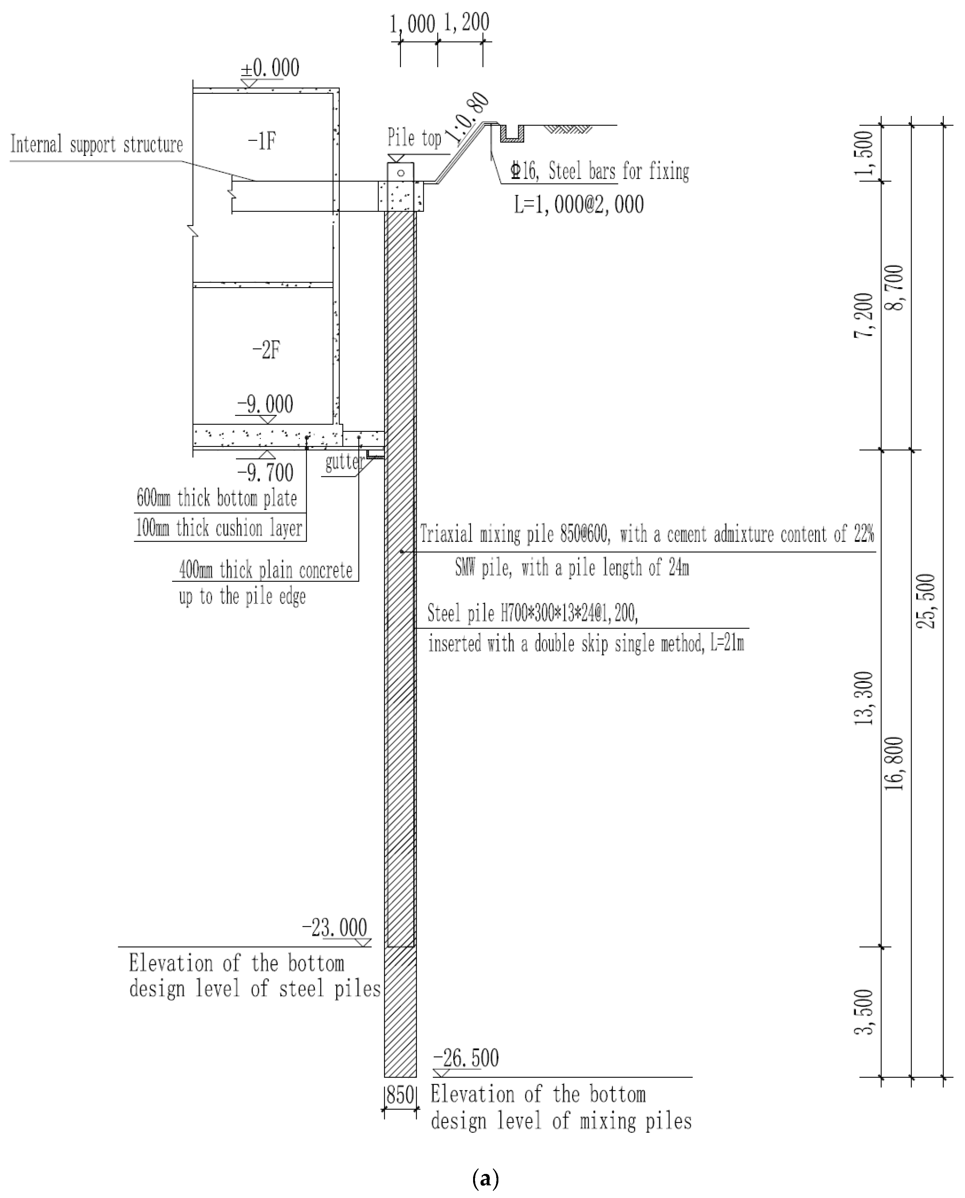
3.1. Support Structure Form

As shown in Figure 1, the foundation pit excavation is supported by SMW combined with an internal concrete support. Within a specific range of the central part of the east side of the foundation pit is sectional view diagram 2-2, while the rest of the locations are in sectional view diagram 1-1. (1) The retaining piles are all SMWs, and the mixing piles are three-axis cement-mixing piles with a length of 21 m (locally 24 m). (2) The horizontal internal support structures are all cast-in-place reinforced-concrete structures, with one support structure installed at a depth of 1.5 m. (3) The columns are composed of steel lattice columns for the upper portion, and the bottom portions are supported by driven (drilled) cast-in-place piles. The support cross-sections are illustrated in Figure 2a,b. The quality of cast-in-place piles can be significantly affected by underground water, as it has a diluting effect on the drilling mud, making it difficult to remove debris and maintain the stability of the borehole walls. This can lead to collapsed sand and gravel layers along the pile wall. Therefore, it was necessary to carry out effective dewatering and waterproofing measures during the excavation of the foundation pit. It was also essential to monitor changes in the groundwater level to ensure the stability of the pile foundation. The excavation of the foundation pit was carried out in sections using mechanical excavation methods. The excavation work began in early January 2020 and continued until the basement slab was poured in early June 2020. The basement construction then proceeded gradually up to the elevation of ±0.00 in late June 2020. The space between the outer wall and the foundation pit was gradually backfilled with soil during this time. In early September 2020, the steel beams began to be removed, and this process continued until late November 2020, marking the completion of the foundation pit construction project.

3.2. SMW

The SMW method is the abbreviation of Soil-Mixing Wall, which was firstly developed successfully by Narayuki Industry Co., Fuzhou, China. The SMW method uses a special multi-shaft mixer to drill into the cutting soil in situ, and at the same time inject cement slurry into the soil at the end of the drill bit, and then insert H-beam steel or other profiles into the mixing piles after sufficient mixing to form a continuous underground wall that can be used as a direct soil-retaining and water-stopping structure. Its main features are a simple structure, good water-stopping performance, short construction period, low cost, and low environmental pollution, and it is especially suitable for foundation pit projects in cities. Based on the actual conditions of this project, the mixing piles used in the foundation pit were Φ850@600 three-axis cement mixing piles, and H70030013*24 steel beams were inserted into the mixing piles with 1200 mm/600 mm spacing.

3.3. Reinforced-Concrete Inner Support

In order to effectively control the deformation of the excavation and ensure the stability and safety of the foundation pit while considering the engineering cost and various factors, a reinforced-concrete internal support was installed at a distance of 1.5 m from the ground level of the site in this project. The internal support system consisted of a combination of ring braces, angle braces, and diagonal braces, and columns were set beneath each intersection of the braces. The design parameters of the supporting structure are shown in Table 2.

4. Excavation Monitoring and Data Analysis

4.1. Monitoring Scheme and Layout of Monitoring Points

Due to the extensive excavation depth and complex surrounding environment of this foundation pit project, it was necessary to monitor the supporting structure and the surrounding environment during the excavation period to ensure the safety of the excavation support structure as well as the surrounding roads, underground pipelines, and other protected structures. Figure 3a shows the plan layout of monitoring points for the excavation project, including 12 monitoring points for deep horizontal displacement (C1 to C12), 26 monitoring points for enclosure settlement and horizontal displacement (P1 to P26), 36 monitoring points for column settlement (L1 to L36), and 4 monitoring points for groundwater level (S1 to S4). Figure 3b shows the plan layout of environmental monitoring points around the excavation project, including 13 monitoring points for adjacent building inclination (QX1 to QX13), 26 monitoring points for adjacent building displacement (J1 to J26), and 14 monitoring points for road and surrounding pipeline settlement and horizontal displacement (D1 to D14). Z1 to Z6 are internal-support-stress-monitoring points.
The monitoring method is as follows. An inclinometer was used for the horizontal displacement monitoring of deep soil mass, 12 inclined points were arranged for monitoring, and a borehole-embedding method was adopted. The embedding depth of the inclinometer tube was 20~21 m, and the embedding was completed before the foundation pit excavation. For monitoring the slope top horizontal displacement, measuring points were set along the crown beam of the foundation pit, observed with the small-angle method, and monitored 108 times in total. The horizontal displacement of the slope top of the supporting structure was monitored by a total station. The observations of column settlement were tested using a precision level, and measuring points were embedded at the position of each support beam column according to design requirements. According to the actual situation around the site, two buildings on the west side and one building on the east side of the foundation pit were monitored. According to the scale of the buildings, 5~8 settlement observation points and 3~6 inclination observation points were arranged for each building. The settlement observation of surrounding roads and underground pipelines was tested using a precision level. For underground water level monitoring, four underground water level observation points were arranged around the foundation pit, and the water level observation was conducted using a steel ruler water level gauge.

4.2. Data Analysis

In order to study the response characteristics of foundation pit excavations in soft-soil areas, this section analyzes the deep horizontal displacement of the support structure, pile top displacement, settlement of surrounding structures, column settlement, and groundwater level changes. Existing studies have shown that there are apparent ‘time-space effects’ during the excavation of foundation pits, and there are some differences in the deformation characteristics at different periods and monitoring points, so the monitoring data of different points and periods were selected for comparative analysis. Foundation pits are often considered a plane-strain problem in calculation and design. However, the deformation of the retaining structure is different in the same direction of pit wall, and has obvious spatial distribution characteristics. It has been shown that the negative corner of a foundation pit can restrain deformation, and the influence of the corner effect will decrease with the increase in distance from the negative corner. According to this principle, some scholars adopt the concept of PSR (maximum displacement of retaining wall at a certain position and plane strain state of retaining wall) to quantitatively describe the spatial effect of foundation pits. Therefore, this paper describes the degree of spatial effects of the foundation pit by comparing the displacement of the supporting structure at different positions.
(1)
Deep Horizontal Displacement
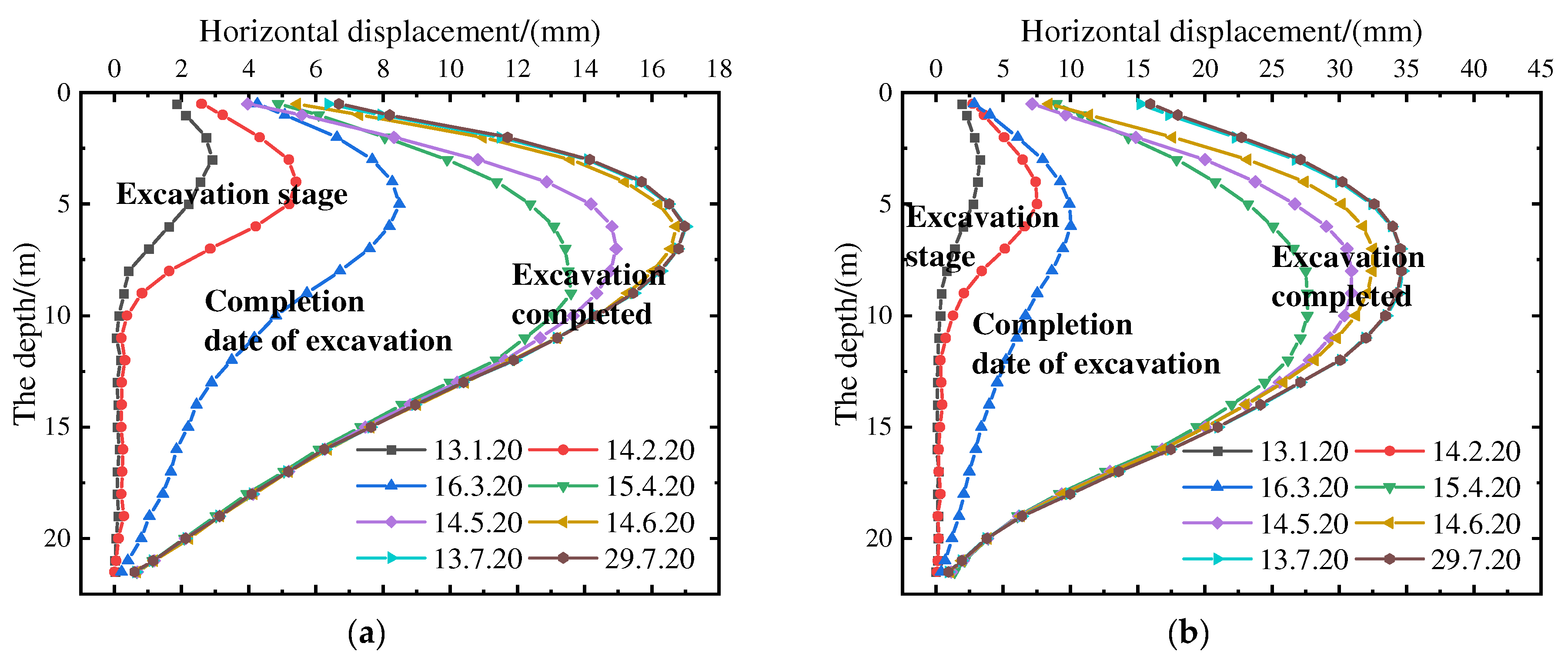
The excavation site had 12 monitoring points for measuring deep horizontal displacement. Taking monitoring points C4 to C6 as an example, the deep horizontal displacement variation curves over different periods are shown in Figure 4. Figure 4 shows that the deep horizontal displacement curves measured at various time points exhibit a bow-shaped distribution, with the displacement values initially increasing and then decreasing as the depth below the excavation site surface increases. With increasing excavation depth, the location of the maximum deep horizontal displacement at each monitoring point gradually shifted downward. Following completion of the excavation, the maximum deep horizontal displacement tended to remain stable and was typically located at a depth of around 6 m. In addition, prior to 16 March 2020, the deep horizontal displacement values at each monitoring point were noticeably smaller due to the relatively shallow excavation depth. Between 26 March and 20 April, the deep horizontal displacement increased rapidly as the excavation progressed. After 20 April, as the excavation was essentially completed, the deep horizontal displacement at each monitoring point gradually approached a state of stability. The deep horizontal displacement of the piles is closely related to the construction conditions of the excavation pit. As the excavation depth gradually increased, the deep horizontal displacement exhibited a progressive change. Therefore, it was necessary to pay special attention to the changes in deep horizontal displacement during the excavation process and strengthen the monitoring frequency during the later stages of excavation. By comparing the deep horizontal displacement monitoring values of monitoring points C4, C5, and C6, it can be observed that the deep horizontal displacement monitoring value of C5 is significantly larger than that of C4 and C6. The maximum deep horizontal displacement value at the C6 monitoring point reached 34.52 mm, while the maximum deep horizontal displacement value at the C4 and C6 monitoring points was only about 17 mm. This is because, generally, the corner of the excavation pit limits the deformation of the excavation pit, and the closer the corner, the smaller the deformation. The C6 monitoring point was located in the middle of the pit wall, far from the corner of the excavation pit, and was less affected by the corner effect. In contrast, the C4 and C6 monitoring points were located at the corner of the excavation pit and were more affected by the corner effect. Hence, the deformation at the C6 monitoring point was more significant than that at the C4 and C6 monitoring points.
Based on the analysis of the horizontal displacement of the top of the pile, it is evident that the bottomless foundation pit supported by the SMW pile combination exhibited a significant ‘spatial effect’. Therefore, in actual engineering, the support structure design in the middle of the foundation pit can be strengthened, and the strength at the corners of the foundation pit can be reduced, thereby reducing the cost of foundation pit construction.
(2)
Analysis of pile top horizontal displacement and settlement
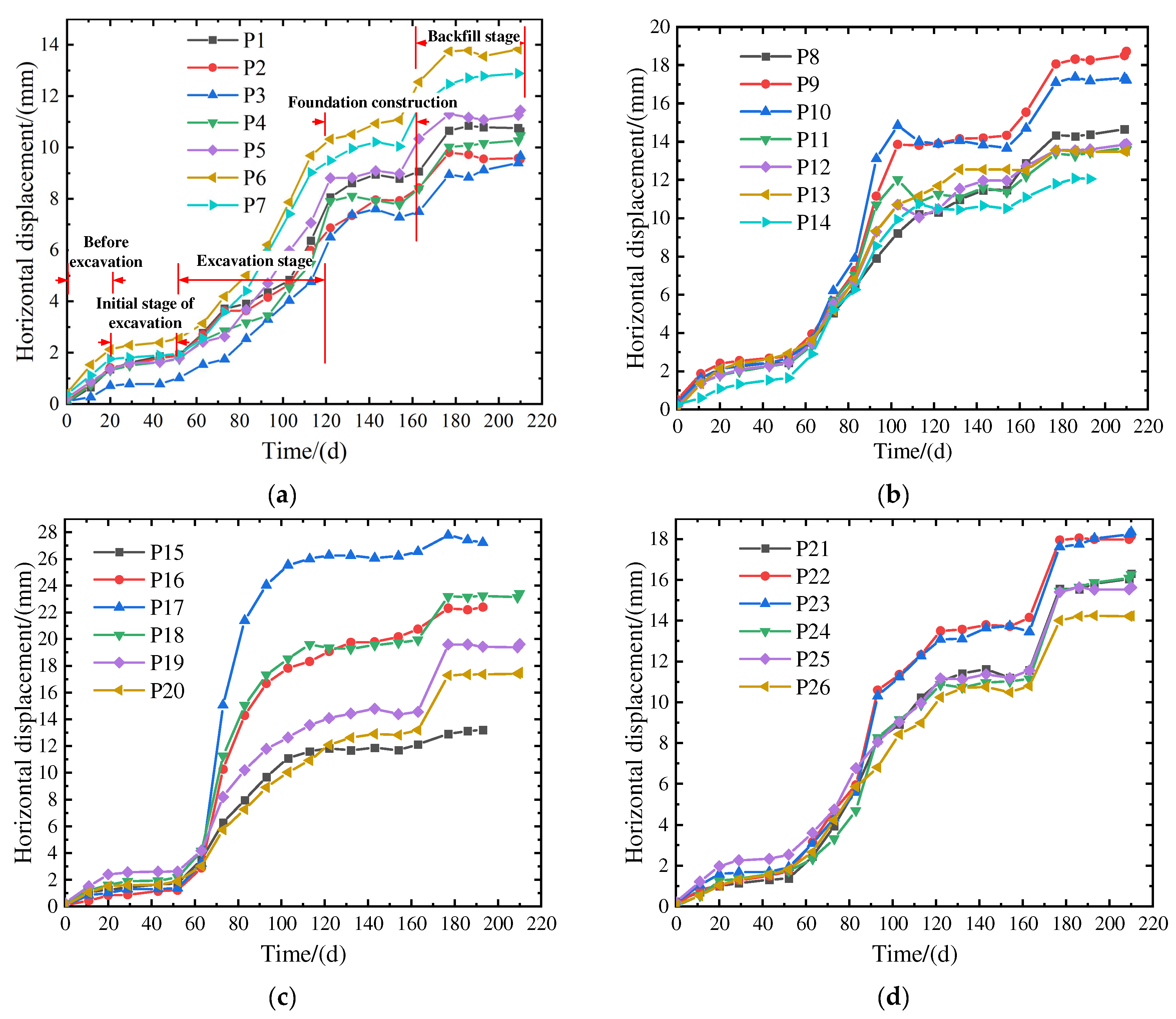
There were a total of 26 monitoring points for pile top displacement (P1~P26), with displacement in the direction inside the excavation pit considered positive. Figure 5 shows the time-dependent curve of pile top horizontal displacement during the excavation process. From Figure 5, it is evident that the horizontal displacement of the pile tops exhibited an apparent ‘time effect’ characteristic during the excavation process. That is, the horizontal displacement of pile tops showed variations over time at different excavation stages of the foundation pit. Around 20 days before the excavation of the foundation pit, there was a significant sharp increase in the horizontal displacement of the pile top. However, during the period from the 20th to the 50th day of excavation, the increase in the horizontal displacement of the pile top was not significant. The reason for this phenomenon is that the stress in the site was released during the initial excavation of the foundation pit, resulting in a sharp increase in the horizontal displacement of the pile top. However, with time, the internal stress redistribution of the soil was gradually completed. In addition, during the period of about 20 to 50 days, the concrete support was cast inside the pit, and the excavation of the foundation pit was not continued, which resulted in the relatively smooth variation in pile top horizontal displacement during this period. After 50 days, as the foundation pit excavation resumed, the pile top’s horizontal displacement again showed a rapid increasing trend. After the completion of the excavation of the foundation pit, with the construction of the foundation slab, the increase in the horizontal displacement of the pile top gradually tended to stabilize. The corresponding construction stages at different times are shown in Figure 5a.
Furthermore, the ‘spatial effects’ were also evident in this excavation. Apart from the northeast corner of the excavation, the horizontal displacement at the mid-position of the excavation wall was significantly greater than that at the corner. This is due to the deformation restriction effect at the excavation’s corner. Usually, the closer the position is to the corner of the excavation, the smaller the deformation. However, due to the presence of existing structures and the loading on the top of the excavation at the northeast corner, the horizontal displacement at P6–P9 in this excavation was relatively large.
The settlement variation curve of the pile top is presented in Figure 6, which also shows prominent distributions characteristic of the ‘time effect’ and ‘spatial effect’. Initially, the pile top settlement rapidly increased due to the excavation, but the curve gradually became smoother due to the construction of concrete support. However, with the continued excavation of the foundation pit, the pile top settlement rapidly increased again. After the completion of the excavation, the settlement variation curve gradually became smoother, and the rate of increase decreased during the construction process of the foundation slab. The spatial distribution pattern of the pile top settlement is consistent with that of the horizontal displacement. Settlement decreases as the location becomes closer to the excavation corner, while it increases as it becomes closer to the middle position of the excavation wall. It also can be seen from Figure 6a that the settlement of point P1 was significantly greater than that of P2, P3, and P4. The reason for this phenomenon is that there were already buildings on the west side of point P1, and these buildings acted on the top of the foundation pit in the form of load, thus causing the settlement of point P1 to increase significantly. This is why the settlement of point P1 was still greater than that of P2, P3, and P4 although the corner was displaced.
(3)
Settlement Analysis of Adjacent Buildings
North of the foundation pit excavation is an area of real estate under construction, south is Jiangbin Avenue, west is the built Hairun Riverside Garden Community, and east is a state-owned building. Both the state-owned assets building and the Garden Community are high-rise buildings, which adopt pile foundations. Figure 7 shows the settlement curves of adjacent buildings over time, recorded 50 days before the foundation pit excavation. It can be observed from Figure 7 that there were significant differences in settlement characteristics among the various monitoring points. However, the accumulated settlement values at each point ranged from 0.34 mm to 6.18 mm, indicating that the overall settlement deformation of the buildings was small. For each settlement monitoring point, no significant fluctuations in settlement values were observed before the foundation pit excavation. When excavation began, the settlement values at each monitoring point showed significant changes. Subsequently, due to the construction of the internal support system, the settlement values became stable again. However, as the foundation pit was re-excavated, the settlement values at each monitoring point showed significant fluctuations and an overall increasing trend with time. After the completion of the excavation, the settlement values gradually stabilized again during the construction of the foundation pit base. It is evident that the construction procedures and sequencing of the excavation not only impact the deformation of the excavation itself but also have implications for the stress distribution and deformation of the surrounding structures. Therefore, it is crucial to pay attention to the impact of excavation construction procedures on the deformation of the surrounding structures during the excavation process.
Furthermore, Figure 7 reveals significant variations in settlement values among monitoring points at different positions, which can be attributed to their varying distances from the excavation site. Taking Figure 7a as an example, it is evident that the settlement values of J1 and J2 are significantly greater than those of J3 to J7. This discrepancy can be attributed to the closer proximity of J1 and J2 to the excavation site, resulting in a more pronounced impact from the excavation process. Furthermore, the different underground structures of different structures are also one of the reasons for the differences in settlement values at different monitoring points.
(4)
Settlement Analysis of Columns
The excavation consists of a total of 36 columns (L1–L36). Figure 8 depicts the variation in column settlements over time. Figure 8 shows that during the initial stage of excavation, the columns did not exhibit significant settlement, and the settlement rate remained relatively stable. However, as the excavation progressed further, noticeable settlement of the columns started to occur, and with increasing excavation depth, the settlement values of the columns exhibited a rapid increasing trend. Starting from day 100, the excavation phase of the basement was largely completed, and the subsequent focus shifted toward the construction of the basement floor. As a result, the settlement values of individual columns began to stabilize gradually after the 100th day, and with the progression of subsequent excavation activities, the variations in column settlement remained relatively small. Clearly, the settlement values of the columns exhibit significant variations during the excavation phase of the foundation pit while demonstrating relatively minor changes during the subsequent stages. Therefore, it is essential to place particular emphasis on monitoring the structural response and deformation of the internal bracing system during the excavation phase of a foundation pit. Moreover, enhancing the monitoring frequency during this stage is necessary.
(5)
Analysis of Displacement Monitoring for Surrounding Roads and Underground Pipelines
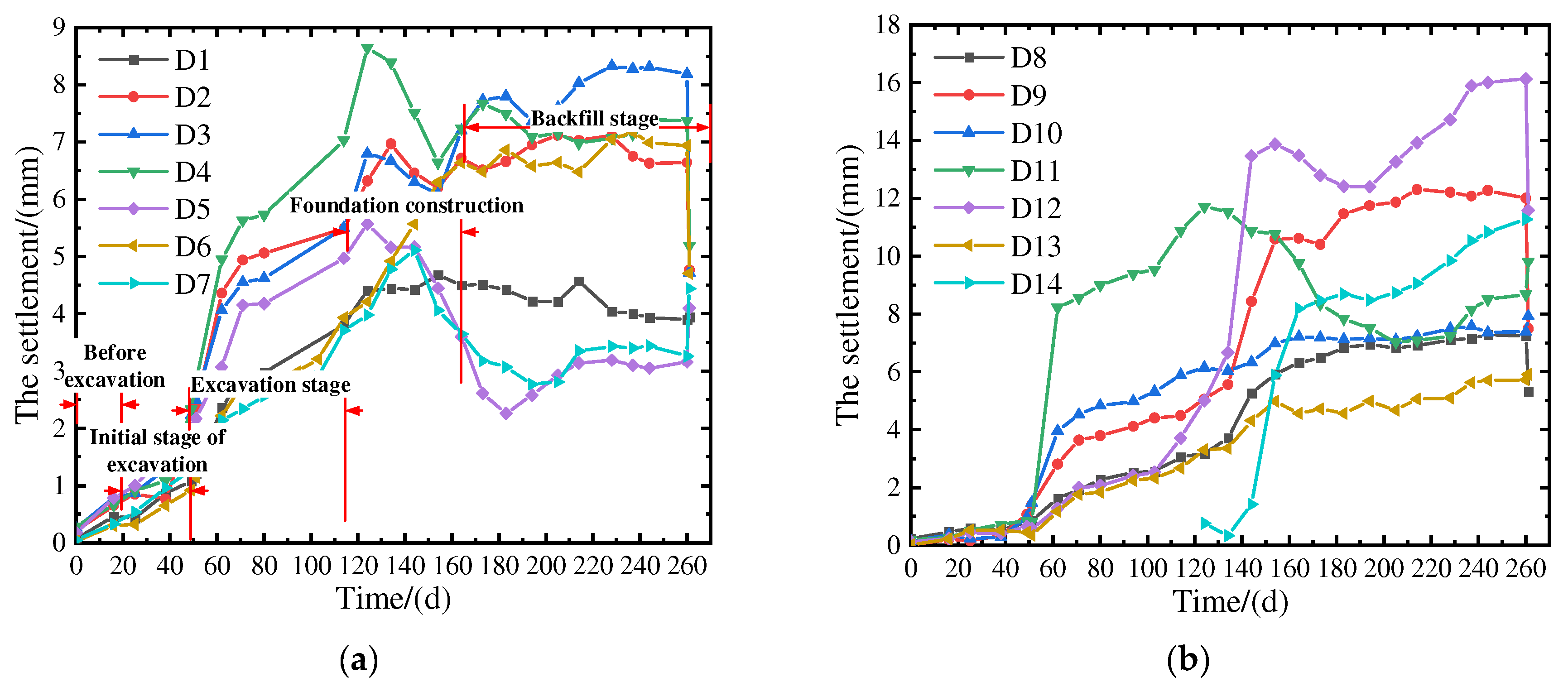
Fourteen displacement monitoring points (D1–D14) were installed for surrounding roads and underground pipelines. Monitoring data were collected starting 50 days prior to the excavation of the foundation pit. Figure 8 and Figure 9 present the time-dependent curves of water level displacement and settlement values for each monitoring point. Based on Figure 9 and Figure 10, it can be observed that prior to the excavation, no significant deformations were detected in the surrounding roads and underground pipelines. Both the horizontal displacement and settlement values were nearly zero. However, after 50 days, when the foundation pit excavation commenced, noticeable variations in horizontal displacement and settlement values were observed at each monitoring point. With the gradual increase in the depth of excavation of the foundation pit, noticeable increases were observed in the horizontal displacement and settlement values of the surrounding roads and underground pipelines. The increase in deformation was also positively correlated with the foundation pit’s excavation depth. Upon completion of the excavation, as the construction of the basement floor and backfilling of the foundation pit took place, the horizontal displacement and settlement values at each monitoring point gradually stabilized. It can be observed that the deformations of the surrounding roads and underground pipelines were primarily concentrated during the excavation phase of the foundation pit. After the excavation, the deformations of the surrounding roads and underground pipelines gradually reached a state of stability, with minimal influence from the construction of the basement floor and backfilling of the foundation pit on the increase in deformation. Furthermore, the accumulated horizontal displacement values at each monitoring point range from 3.70 to 13.86 mm, while the accumulated settlement values range from 3.91 to 24.52 mm, all of which meet the design requirements.
(6)
Analysis of Underground Water Level Monitoring
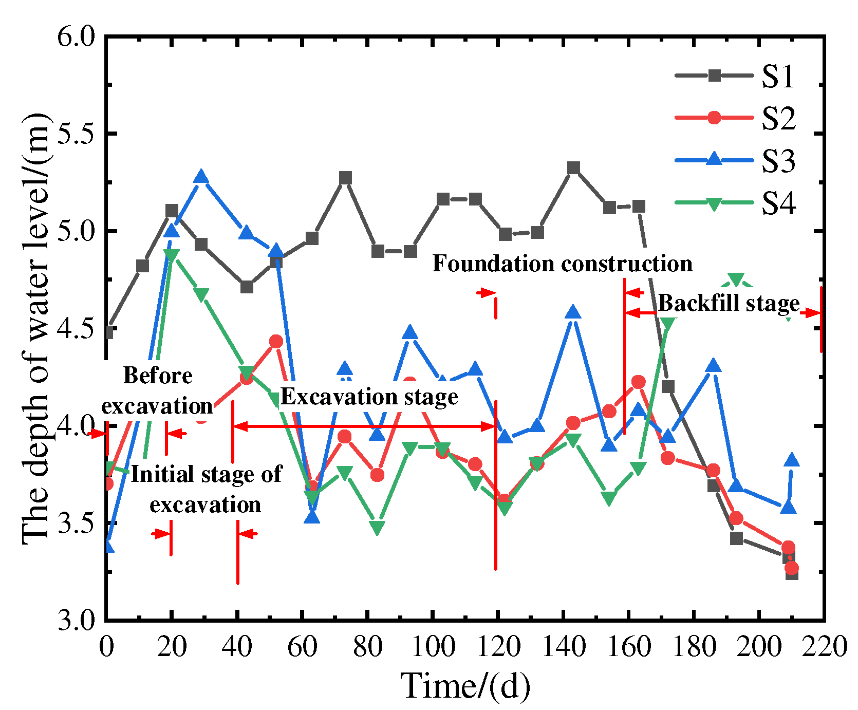
Four monitoring points (S1~S4) were established for monitoring the variations in underground water levels during the foundation pit excavation. Figure 11 illustrates the changes in groundwater level with respect to the excavation. Based on Figure 11, it is evident that during the excavation phase of the foundation pit, the groundwater levels at each monitoring point exhibit a fluctuating trend. The maximum cumulative variation in groundwater levels ranges from 0.812 to 1.856 m. Importantly, during the excavation of the foundation pit and the subsequent construction of the underground structure, monitoring points S1 and S3 recorded cumulative variations that exceeded the predefined threshold of 1000 mm, indicating an alert level. This can be primarily attributed to significant rainfall events occurring during the initial pit excavation and the subsequent underground construction process, resulting in substantial fluctuations in groundwater levels at these specific monitoring points. According to the monitoring results, the initial buried depth of the groundwater level before foundation pit excavation was between 3.670~4.870 m, and the maximum accumulated variation in groundwater level around the foundation pit excavation and basement construction was 0.812~1.856 m. Table 3 shows the observation data for the groundwater level around the foundation pit.
(7)
Stress analysis of inner support structure
As shown in Figure 12, the stress of the inner support at the Z1 and Z4 monitoring points was relatively small at the early stage before excavation, and Z1 was a positive value. This is because the internal bracing structure was mainly affected by the weight of the structure at the initial stage of excavation and shows the characteristics of tension. With the start of foundation pit excavation, the structure was gradually subjected to the effect of the foundation pit slope and became compressed; at this time, the stress became negative. With continuous excavation, the pressure on the internal support structure became larger and larger; at this time, the reinforcement stress continued to increase. When the excavation was completed, the stress of the inner support gradually decreased during the backfilling of the foundation pit.
(8)
Summary of data
During the whole excavation process, the maximum horizontal displacement of the deep soil was 14.46~41.74 mm. The cumulative horizontal displacement of slope top was 9.53~27.22 mm; the cumulative settlement of the slope top was 7.03~22.48 mm; and the accumulated settlement of the columns ranged from −3.75 mm to −0.84 mm. During excavation, the maximum cumulative displacement of the horizontal displacement monitoring point C11 of deep soil was 41.74 mm, exceeding the allowable design value (40 mm), and the cumulative change and change rate of other monitoring points did not exceed the design warning value. After the foundation pit bottom was sealed, the deformation rate of the retaining structure tended to stabilize. The settlement and inclination rates of adjacent buildings were normal, all within the allowable design value range, the accumulated settlement of the adjacent buildings was 0.34~6.18 mm, and the accumulated inclination change rate of the adjacent buildings was −0.03 ‰~0.03 ‰, all within the allowable design value range. The cumulative horizontal displacement of surrounding roads and underground pipelines was 3.70~24.64 mm, and the cumulative settlement of surrounding roads and underground pipelines was 3.91~50.04 mm. The maximum cumulative variation in groundwater level was 0.812~1.856 m. During the foundation pit excavation and basement construction, the maximum cumulative variation in monitoring points S1 and S3 exceeded the warning value (1000 mm). Combined with the deformation results of the surrounding roads, it shows that the change in water level has great influence on the surrounding environment. Reinforcing the bar stress of the ring beam and supporting beam: According to the observation results, the accumulative change from reinforcing the bar stress of the ring beam and supporting beam was −163.84~150.11 MPa (a negative value “−” indicates compression). All were within the allowable design range.
It is worth noting that different foundation pit projects have their unique characteristics, and this paper only analyzes a single foundation pit. In order to understand the soft-soil area more comprehensively, the response of ring support combined with SMW pile support to deep foundation pit excavation needs more analysis. In addition, the monitoring method in this paper is also more traditional, and is affected by climate, construction methods, and other factors. In the future, intelligent monitoring methods can be used to analyze responses to the excavation of foundation pits.

5. Conclusions

This study was conducted in the context of an actual engineering project to investigate the excavation response of a bottomless foundation pit supported by a combination of SMW piles in soft-soil areas. The research primarily focuses on analyzing the displacement of the combined SMW piles, the settlement of columns, the deformation of surrounding structures, and the changes in groundwater levels. It also summarizes the specific deformation of the supporting structure in a construction method combining SMW piles in a soft-soil area and of the surrounding environment by analyzing the deformation during the foundation pit excavation process at different locations, and gives some suggestions to guide the design and construction of foundation-pit-supporting structures in soft-soil areas. Based on the analysis of these parameters, the following significant conclusions are obtained:
(1)
The deformation of the combined circular internal bracing and SMW support structure in excavation projects exhibits distinct spatial distribution characteristics. Generally, the deformation lessens as the distance from the excavation corner increases, while the middle sections of the excavation walls experience more significant deformations. The excavation can also increase the deformation of the support structure. Therefore, in practical engineering, it is advisable to enhance the monitoring points or monitoring frequency in the middle section of the excavation walls and near existing structures near the top of the excavation to ensure the safety of the excavation.
(2)
During the construction phase, the deformations of the internal support combined with the SMW support structure exhibit a significant time effect, meaning that the deformation characteristics of the support structure vary at different excavation stages. Typically, during the initial excavation and construction phases of the internal support structure, the deformation growth rate of the support structure is relatively low. During the excavation construction phase, as the foundation pit’s excavation depth increases, the support structure’s deformation growth rate significantly increases. However, during the construction of the foundation base and backfilling of the excavation pit, the deformation growth rate of the support structure decreases significantly. Therefore, to ensure the safety of excavation construction, it is essential to closely monitor the deformation of the internal support system composed of SMW piles, particularly during the excavation phase. This will help prevent sudden excessive deformations of the support structure.
(3)
The deformations of the surrounding structures also demonstrate a notable ‘time effect’. Based on the analysis of monitoring data from the surrounding structures, it is evident that the settlements of adjacent buildings and the deformations of surrounding roads and underground pipelines are primarily concentrated during the excavation phase of the foundation pit. Subsequently, upon completion of the excavation, the deformations of the surrounding roads and underground pipelines gradually stabilize, with minimal impact from the construction of the basement floor and backfilling of the foundation pit. Furthermore, the closer the structures are to the foundation pit, the greater their deformations. Therefore, to ensure the safety of the surrounding structures during the excavation of the foundation pit, it is crucial to pay close attention to the deformations of the structures.
(4)
Throughout the entire period of construction of the foundation pit, the groundwater level exhibited a fluctuating deformation trend. Apart from the influence of rainfall, the variations in groundwater level were insignificant, indicating the effective water-sealing performance of the support system formed by the combination of internal supports and SMW piles.

Author Contributions

Conceptualization, B.T. and J.Z.; methodology, S.Y.; validation, M.S. and B.T.; formal analysis, B.T.; investigation, J.Z.; resources, S.Y.; data curation, M.S.; writing—original draft preparation, S.Y.; writing—review and editing, S.Y; supervision, B.T.; project administration, J.Z.; funding acquisition, S.Y. All authors have read and agreed to the published version of the manuscript.

Funding

This work was supported by the Collaborative Innovation Platform Project of Fuzhou-Xiamen-Quanzhou National Self-Innovation Zone (Grant No. 3502ZCQXT2022002), the Science and Technology plan of Fujian Province (Grant No. 2022I0014), the Construction Technology Project of Xiamen Municipal Construction Bureau (Grant No. XJK2022-1-12), and the Fundamental Research Funds for the Central Universities (Grant No. ZQN-1012).

Data Availability Statement

Due to legal issues and trade secrets, the monitoring data in this article cannot be provided free of charge. Nevertheless, all concepts and data are explained in the submitted studies, and some studies are available upon request.

Conflicts of Interest

The authors declare no conflict of interest.

References

  1. Ou, C.Y.; Hsieh, P.G.; Chiou, D.C. Characteristics of ground surface settlement during excavation. Can. Geotech. J. 1993, 30, 758–767. [Google Scholar] [CrossRef]
  2. Wong, I.H.; Poh, T.Y.; Chuah, H.L. Performance of excavations for depressed express Engineering in Singapore. J. Geotech. Geoenviron. Eng. 1997, 123, 617–625. [Google Scholar] [CrossRef]
  3. Huang, M.S.; Wang, W.D.; Zheng, G. A review of recent advances in the underground engineering and deep excavations in soft soils. China Civ. Eng. J. 2012, 45, 146–161. [Google Scholar]
  4. Ye, S.H.; Huang, A.P.; Gao, S. Deformation characteristics and environmental impact analysis of deep foundation pit excavation in a subway station in Lanzhou. Water Resour. Hydropower Eng. 2020, 51, 12–22. [Google Scholar]
  5. Lee, F.H.; Yong, K.Y.; Quan, K.; Chee, K.T. Effect of corners in strutted excavations: Field monitoring and case histories. J. Geotech. Geoenviron. Eng. 1998, 124, 339–349. [Google Scholar] [CrossRef]
  6. Cheng, J.L.; Li, Y.Z.; Liu, X.Z.; Wen, G.X. Application of many concentric ring supports with large diameter in super deep foundation pits. Chin. J. Geotech. Eng. 2014, 36 (Suppl. 1), 122–126. [Google Scholar]
  7. Li, Y.; Gu, K.Y.; Lin, J. Design method for bracing of asymmetric cylindrical foundation pits. Chin. J. Geotech. Eng. 2013, 35 (Suppl. 2), 888–891. [Google Scholar]
  8. Liu, G.; Guo, J.; Li, M.; Qin, T.; Huang, P. Measured behaviors of an oversized irregular basement excavation and its surrounding responses in thick soft clay. Arab. J. Geosci. 2019, 13, 3. [Google Scholar] [CrossRef]
  9. Wang, J.H.; Xu, Z.H.; Wang, W.D. Wall and ground movements due to deep excavations in Shanghai soft soils. J. Geotech. Geoenviron. Eng. 2020, 136, 985–994. [Google Scholar] [CrossRef]
  10. Finno, R.J.; Arboleda-Monsalve, L.G.; Sarabia, F. Observed performance of the one museum park west excavation. J. Geotech. Geoenviron. Eng. 2015, 141, 04014078. [Google Scholar] [CrossRef]
  11. Ye, S.; Zhao, Z.; Wang, D. Deformation analysis and safety assessment of existing metro tunnels affected by excavation of a foundation pit. Undergr. Space 2021, 6, 421–431. [Google Scholar] [CrossRef]
  12. Ye, S.H.; Zhou, J. Study on stress and deformation of shield tunnel plate under unloading of foundation pit excavation. Arab. J. Geosci. 2021, 14, 1–14. [Google Scholar] [CrossRef]
  13. Wu, J.; Ye, S.H.; Wang, Z.Q.; Yang, D. Application and automatic monitoring and analysis of hybrid support structure in ultra-deep foundation pit engineering in the Lanzhou area under complex environmental conditions. Water 2023, 15, 1335. [Google Scholar] [CrossRef]
  14. Ye, S.H.; Li, D.P. Monitoring and simulation analysis of deep and large foundation pit excavation in complex environment. China Civ. Eng. J. 2019, 52 (Suppl. 2), 117–126. [Google Scholar]
  15. Tan, Y.; Lu, Y.; Wang, D. Deep excavation of the gate of the orient in Suzhou stiff clay: Composite earth-retaining systems and dewatering plans. J. Geotech. Geoenviron. Eng. 2018, 144, 05017009. [Google Scholar] [CrossRef]
  16. Ou, C.Y.; Shiau, B.Y.; Wang, I.W. Three-dimensional deformation behavior of the Taipei National Enterprise Center (TNEC) excavation case history. Can. Geotech. J. 2000, 37, 438–448. [Google Scholar] [CrossRef]
  17. Ou, C.Y.; Hsieh, P.G.; Lin, Y.L. Performance of excavations with cross walls. J. Geotech. Geoenviron. Eng. 2010, 137, 94–104. [Google Scholar] [CrossRef]
  18. Chen, W.; Cui, W. Study on monitoring of deep foundation pit with SMW engineering method plus anchor cable retaining structure. AIP Conf. Proc. 2018, 1944, 020016. [Google Scholar] [CrossRef]
  19. Feng, Z.Y.; Xu, Q.; Xu, X.Y.; Tang, Q.; Li, X.D.; Liao, X. Deformation Characteristics of Soil Layers and Diaphragm Walls during Deep Foundation Pit Excavation: Simulation Verification and Parameter Analysis. Symmetry 2022, 14, 254. [Google Scholar] [CrossRef]
  20. Chen, S.R.; Cui, J.F.; Liang, F.Y. Case Study on the Deformation Coupling Effect of a Deep Foundation Pit Group in a Coastal Soft Soil Area. Appl. Sci. 2022, 12, 6205. [Google Scholar] [CrossRef]
  21. Kiet, H.N.; Phien-wej, N. Advanced soil parameters determination for Ho Chi Minh city soft clay to predict ground movements in deep excavations and tunneling. In Proceedings of the 4th International Conference on Geotechnics for Sustainable Infrastructure evelopment (GEOTEC HANOI), Hanoi, Vietnam, 28–29 November 2019; pp. 497–504. [Google Scholar]
  22. Panchal, J.P.; McNamara, A.M.; Stallebrass, S.E. A new approach to modelling excavations in soft soils. In Proceedings of the 9th International Conference on Physical Modelling in Geotechnics (ICPMG), London, UK, 17–20 July 2018; pp. 1445–1450. [Google Scholar]
  23. Ding, Y.; Wang, P.; Yu, S. A new method for deformation monitoring on H-pile in SMW based on BOTDA. Measurement 2015, 70, 156–168. [Google Scholar] [CrossRef]
  24. Xian, Q.; Wang, Z.; Liu, X.; Ma, S.; Xiao, Z. Site Measurement Study on Mechanical Properties of SMW Piles of Building Structures in Sandy Soil Areas. Buildings 2022, 12, 1733. [Google Scholar] [CrossRef]
  25. Chen, W.Z.; Gao, Q.C.; Jiang, J.S. Simulation experimental research for the influence of embedded ratio on SMW’s working traits. Adv. Mater. Res. 2011, 250–253, 2322–2326. [Google Scholar] [CrossRef]
  26. Finno, R.J.; Voss, F.T.; Rossow, E.; Blackburn, J.T. Evaluating damage potential in buildings affected by excavations. J. Geotech. Geoenviron. Eng. 2005, 10, 131. [Google Scholar] [CrossRef]
  27. Son, M.; Cording, E.J. Estimation of building damage due to excavation-induced ground movements. J. Geotech. Geoenviron. Eng. 2005, 131, 162–177. [Google Scholar] [CrossRef]
  28. Asker, K.; Fouad, M.T.; Bahr, M.; El-Attar, A. Numerical analysis of reducing tunneling effect on viaduct piles foundation by jet grouted wall. Min. Miner. Depos. 2021, 15, 75–86. [Google Scholar] [CrossRef]
  29. Sharma, J.S.; Hefny, A.M.; Zhao, J.; Chan, C.W. Effect of large excavation on deformation of adjacent mrt tunnels. Tunn. Undergr.Space Technol. 2001, 16, 93–98. [Google Scholar] [CrossRef]
  30. Huang, X.; Schweiger, H.F.; Huang, H. Influence of deep excavations on nearby existing tunnels. Int. J. Geomech. 2013, 13, 170–180. [Google Scholar] [CrossRef]
Figure 1. Birds-eye view of the layout of the support structure.
Water 15 03430 g001
Figure 2. Sectional view diagrams of the supporting structure: (a) Sectional view diagram 1-1. (b) Sectional view diagram 2-2.
Water 15 03430 g002aWater 15 03430 g002b
Figure 3. Layout plan of monitoring points: (a) Layout plan for excavation monitoring points. (b) Layout plan for monitoring points of surrounding structures.
Water 15 03430 g003
Figure 4. The deep horizontal displacement curve: (a) C4. (b) C5. (c) C6.
Water 15 03430 g004aWater 15 03430 g004b
Figure 5. The curve of horizontal displacement variation at pile top: (a) P1 to P7. (b) P8 to P14. (c) P15 to P20. (d) P21 to P26.
Water 15 03430 g005
Figure 6. The curve of settlement variation at pile top: (a) P1 to P7. (b) P8 to P14. (c) P15 to P20. (d) P21 to P26.
Water 15 03430 g006
Figure 7. The curve of settlement variation in adjacent structures: (a) J1 to J7. (b) J8 to J14. (c) J15 to J20. (d) J21 to J26.
Water 15 03430 g007
Figure 8. Column settlement change curves: (a) L1 to L9. (b) L10 to L18. (c) L19 to L27. (d) L28 to L36.
Water 15 03430 g008
Figure 9. The curves of horizontal displacement changes: (a) D1 to D7 (b) D8 to D14.
Water 15 03430 g009
Figure 10. The curves of settlement changes: (a) D1 to D7 (b) D8 to D14.
Water 15 03430 g010
Figure 11. The curve of groundwater level changes.
Water 15 03430 g011
Figure 12. Stress variation in internal support structure.
Water 15 03430 g012
Table 1. Basic information of each soil layer.
Soil LayerLayer NameThickness/mHeaviness γ/kN/m3Moisture Content/%Cohesion c/kPaInternal Friction Angle φ/°Compression Modulus E/Mpa
1Miscellaneous fill ( Q 4 ml )1.40~7.4017.5/910.03
2Muddy soil ( Q 4 m )0.60~2.2017.229.912.37.073.02
3Medium sand ( Q 4 al )7.30~19.4019.043.752617
3ASilty soil (sandy) ( Q 4 m )0.80~5.0016.432.614.669.913.61
3BSilt ( Q 4 al )2.10~3.5019.028.152311
4Silty soil (sandy) ( Q 4 m )1.20~13.0016.533.313.7110.613.69
5Silty clay ( Q 4 al )1.20~4.8019.232.916.117.0615
6Medium sand ( Q 4 al )11.40~20.2019.328.95308.47
Table 2. Design parameters.
TypeSize (HB)Concrete StrengthReinforcement
ring braces900 mm′2000 mmC3032C25
angle braces800 mm′900 mmC3022C25
diagonal braces700 mm′800 mmC3020C25
crown beam900 mm′1300 mmC3014C25 + 4C20 + 8C22
Table 3. Groundwater level observation data around foundation pit.
Monitoring Point NumberS1S2S3S4
Buried depth of initial water level (m)4.543.674.873.95
Maximum water level buried depth (m)5.6244.4825.2724.882
Buried depth of minimum water level (m)3.2443.3253.0143.074
Maximum cumulative variation (m)1.2960.8121.8560.932
Buried depth of final water level (m)3.2443.2683.8164.681
Disclaimer/Publisher’s Note: The statements, opinions and data contained in all publications are solely those of the individual author(s) and contributor(s) and not of MDPI and/or the editor(s). MDPI and/or the editor(s) disclaim responsibility for any injury to people or property resulting from any ideas, methods, instructions or products referred to in the content.