Article

Application of a VOF Multiphase Flow Model for Issues concerning Floating Raft Aquaculture

1
Liaoning Ocean and Fisheries Science Research Institute, Dalian 116023, China
2
Key Laboratory of Protection and Utilization of Aquatic Germplasm Resource, Ministry of Agriculture and Rural Affairs, Dalian 116023, China
3
National Marine Environmental Monitoring Center, Dalian 116023, China
*
Authors to whom correspondence should be addressed.
These authors contributed equally to this work.
Water 2023, 15(19), 3450; https://doi.org/10.3390/w15193450
Submission received: 16 August 2023 / Revised: 25 September 2023 / Accepted: 28 September 2023 / Published: 30 September 2023
(This article belongs to the Section Water, Agriculture and Aquaculture)

Abstract

:
Floating raft aquaculture has gradually become a mainstream aquaculture model in the waters of Changhai County, Dalian. To quantitatively describe the impact of floating raft aquaculture facilities on the hydrodynamic environment of nearby sea areas, in this study, we took a single floating raft aquaculture structure as the research object and built a numerical prediction model for water flows passing through the floating raft aquaculture structure using a six-degree-of-freedom VOF (volume of fluid) multiphase flow simulation method based on an overset moving mesh system. Then, we verified the numerical model by utilizing oblique hydraulic jumps and water flows passing through a submerged bar. As shown by the findings, the simulated values are in good agreement with the theoretical solutions and measured values, indicating that the model features high precision and great stability. The impact of the raft area on the hydrodynamic force was introduced into the source term of an equation for consideration. In order to further determine the hindering effect of the raft body on the water body, transport equations and the tracer method were used to simulate the impact of floating raft aquaculture facilities on the water exchange performance of nearby sea areas. This study shows that the VOF multiphase flow model can be easily and accurately applied to studies on floating raft aquaculture, which can greatly reduce the limitations of experiments that utilize pure hydraulic models, wherein the impacts of floating raft aquaculture facilities on hydrodynamic force are generally considered simply based on observations, water roughness or the secondary drag force coefficient, thereby effectively improving the scientific understanding of the physical mechanism involved in floating raft aquaculture.

1. Introduction

In nature and engineering, most of flow phenomena are multiphase mixed flows, and phases can be divided into a solid phase, liquid phase and gas phase. A multiphase flow model is a mathematical method developed to describe the physical laws or phenomena of interactions among these phases. These models are widely applied in a variety of fields, such as fluid simulation, automobiles, heat conduction and medicine. In some commercial software, multiphase flow models have been included to solve some practical issues in engineering, which not only provide an in-depth understanding of the model-based method, but also feature easy operation, debugging and fast data processing, helping engineers find and solve problems and seek optimization during the design stage. Multiphase flows are most commonly seen in issues concerning gas–liquid two-phase flows that describe the interactions between gas and liquid. This simulation method is widely used, especially in the fluid simulation in CFD [1,2,3,4,5,6,7,8,9,10], and is well received among researchers from research institutes and universities. When it comes to CFD, Gao et al. [1] utilized OpenFOAM, an open-source software package in CFD, to study how the spectral peak period and the focused wave amplitude would affect the free surface motion in the gap and the wave loads that acted on the two boxes. The findings show that all the relevant physical quantities are closely dependent on the spectral peak period and the focused wave amplitude. Gao et al. [3] used a Boussinesq-type model to investigate Bragg reflection on a sinusoidal strip and its coupling effect with the port, and put forward a physical process decomposition method to reveal the inherent mitigation mechanism. In addition, they also examined the conditions under which port resonance was not excited by incident waves, and discussed the similarities and differences in the mitigation mechanisms between port resonance and non-resonant conditions. Finally, based on the port resonance conditions, the influence of the number and amplitude of the sinusoidal bars on the optimal vibration attenuation effect and the optimal bar wavelength was systematically analyzed to achieve the optimal vibration attenuation effect, fully demonstrating the remarkable effectiveness of using Bragg reflection to mitigate port resonance. Gao et al. [5] investigated the fluid resonance in the narrow gap between two side-by-side boxes based on OpenFOAM, an open-source software package in CFD. The upstream box swung freely under the action of the waves, while the downstream box remained fixed. The key hydrodynamic behaviors considered in their study included wave heights within the gap, heave displacements and their harmonic components, as well as reflection, transmission and energy loss coefficients. The findings showed that the heave motion of the upstream box increased the fluid resonance frequency and significantly reduced the resonance wave height in the gap. Based on this observation, the frequencies of the maximum and minimum heave displacements of the upstream box deviated from the fluid resonance frequency to a significant extent. Gao et al. [6] used FUNVAVE 2.0, a fully nonlinear Boussinesq model, to simulate the Bragg reflection and its interactions with the port. For this purpose, an elongated port with a constant depth was considered, outside which a series of sinusoidal reinforcement bars with different amplitudes and quantities were deployed. Incident waves, including regular long waves and two-color short-wave groups, were taken into consideration. This study revealed, for the first time, that Bragg resonant reflection could significantly mitigate port resonance for both types of incident waves. The impacts of the quantity and amplitude of sinusoidal bars on the port resonance mitigation effect, as well as on the optimal wavelength of the sinusoidal bars that could achieve the optimal mitigation effect, were comprehensively investigated, which revealed that the first two factors had a significant impact on the latter two parameters. This study provides a new method for mitigating port oscillations by changing the bottom surface.
Multiphase flow models specifically include the Eulerian Model, Volume Fluid Model, Discrete Phase Model, Mixture Model, etc., which have been applied in many professional fields. For example, Gallerano et al. [11] proposed a simulation model of aeroelasticity in long-span bridges, wherein the unsteady Reynolds-averaged Navier–Stokes equation formulated by using the arbitrary Lagrangian–Eulerian (ALE) approach and the finite volume scheme on moving mesh were subject to numerical integration to simulate the aerodynamic field and adapt to the structural motion in the form of moving mesh. Hessenthaler et al. [12] verified, in detail, the Arbitrary Lagrangian–Eulerian fluid–structure interaction technique by using a benchmark experiment for three-dimensional fluid–structure interactions, wherein spatial refinement with three mesh gradient levels and a working condition with two fluid domain lengths were studied, and a series of increasing time steps in a steady state were adopted. A comparison showed that the numerical results were in good agreement with the experimental data. Lindgren et al. [13] investigated the impact of fluid–structure interactions on underwater oscillating structures and carried out experiments on a submerged oscillating box. Habeeb et al. [14] obtained numerical simulation results for a fluid structure in a circular tube heat exchanger based on the commercial code ANSYS. Sangalli et al. [15] put forward a multiphase solution for numerical simulations of actively controlled bridge flutter instability. They used the explicit two-step Taylor–Galerkin method and Arbitrary Lagrangian–Eulerian (ALE) description to solve basic flow equations, the finite element method for spatial discretization and large eddy simulation (LES) to simulate flow turbulence to close a set of equations. In addition, a partitioned coupling scheme was used for the multiphase flow simulation.
The VOF (volume of fluid) multiphase flow method is commonly used in hydromechanics and is widely used in the simulation of the gas–liquid two-phase flow interface in hydromechanics: for example, the free -surface motion of fluid after a dam break. A VOF model can be used to simulate the interface between waves and seawater, as well as bubbles and droplets in the ocean in ocean engineering; phenomena such as spray and combustion in mechanical engineering; reactions between liquids and gases in chemical engineering, etc. VOF models consume a large amount of computing resources, so it is necessary to ensure that the computer hardware and software meet the requirements of the simulation, especially for large-scale simulations involving large spaces and long timescales. Kassiotis et al. [16] proposed a method for calculating the impact of free surface flows on nonlinear structures. The chosen method depended on a partitioning strategy that allowed for strongly coupled multiphase interactions to be solved, wherein the Lagrangian approach was used for representation and the finite element method was used to discretely solve the problem. In the free surface flow method, the volume of fluid (VOF) strategy formulated in the Arbitrary Lagrangian–Eulerian (ALE) framework was taken into account, and finite volumes were used to discretely solve the problem. The model has been verified with 2D and 3D examples.
In recent years, floating raft aquaculture in seawater has gradually become a typical model of aquaculture in shallow sea areas in Dalian. The arrangement of raft facilities in a seawater space hindered the movement of water, had a certain impact on the hydrodynamic environment in the sea area near the aquaculture area and reduced the exchange rate of the water body in the aquaculture area, thereby weakening the ability of local water flows to carry out convective diffusion and the transport of substances. Therefore, in response to this problem, some aquaculture operators and fishery departments have been making efforts to find a method that can scientifically describe the impact of their aquaculture facilities on water flows, which allows aquaculture operators to accurately understand the degree of impact and manage aquaculture in a targeted and scientific manner, so as to protect the “blue granary” described in the strategic plan for the development of the marine economy under the “14th Five-Year Plan”. To accurately and quantitatively describe the hydrodynamic environment of a floating raft aquaculture area and its impact on water exchange performance, researchers have proposed a series of research methods. For example, He et al. [17] carried out a comparative analysis of the on-site hydrodynamic observation data collected before and after the beginning of aquaculture in a raft aquaculture area for kelp in Sanggou Bay, the most open bay in the Shandong Province, to quantitatively describe the distribution characteristics of the hydrodynamic environment in the raft aquaculture area. Klebert et al. [18] considered data on flow velocity and turbulence in a cage aquaculture area in layers using an acoustic Doppler current profiler (ADCP) and analyzed the characteristics of changes in the hydrodynamic field there. Ji et al. [19] analyzed the impact of shellfish aquaculture on the hydrodynamic environment of Sanggou Bay based on collected and complementary observation data, wherein the significant impact of high-density shellfish aquaculture on water exchange performance was discussed and emphasized. Scott et al. [20] calibrated the kinetic energy obtained in a laboratory flume experiment using horizontal velocity, Reynolds stress and vertical profiles of turbulent flows, wherein the change in the empirical correlation-based drag coefficient in the vertical direction was also taken into account, and quantitatively described the nutrient transport conditions affected by various aquaculture structures with calibrated turbulence parameters and drag coefficients. In order to comprehensively understand the flow of seawater through aquaculture facilities in an open-sea area of Changhai County, Dalian, Liaoning Province, Wang et al. [21] introduced a dual-resistance model wherein the secondary drag force coefficient was considered to describe the impact of the floating raft facilities and organisms on the hydrodynamic environment. Zhang et al. [22] estimated and evaluated the characteristics of hydrodynamic force and sediment transport under natural and aquaculture conditions based on observation data from a suspended kelp aquaculture area in Haini Bay.
To sum up, the findings of these researchers provide valuable insight for the study described in this paper; however, most of the solutions involved research methods such as observation and pure hydraulic numerical simulation, with the VOF multiphase flow model still rarely being used to study this physical mechanism. The VOF multiphase flow model can perform modeling for two or more immiscible fluids by solving a set of momentum equations and tracking the volume fraction of each fluid across the domain, being the most accurate simplified multiphase flow model and the most frequently used in the simulation of gas–liquid two-phase flows. Therefore, in this study, we used a floating raft aquaculture area located in a sea area near Changhai County, Dalian as the research area, and built a six-degree-of-freedom VOF numerical multiphase flow model of a small-scale sea area surrounding the floating raft aquaculture area based on an overset dynamic mesh discretization system. It takes many machine-hours for the VOF method to reconstruct a free surface; furthermore, when it comes to computation for physical problems involving an aquaculture area in a large water area, VOF requires a high-performance server or even a cloud platform to meet the conditions of computation. So in this study, we took a single raft as the research case. Based on the ANSYS Fluent platform and secondary development functions [23], we proceeded from the Navier–Stokes equation, took into consideration the volume fraction of each phase and used Fluent’s built-in macros to set the boundary conditions and correlation coefficient through UDF (User-Defined Function) programming under the standard k-ε turbulence model. On the basis of the generation of three-dimensional staggered overset move mesh for a single raft and the surrounding sea area, the impact of the hanging cage or net cage was considered with the porous jump model, and the three-directional moment of inertia was introduced to reflect the actual motion state of the floating ball in accordance with the actual scenario. In order to fully verify the simulation accuracy of the multiphase flow model used in this study for practical problems, we verified the accuracy and stability of the model via the problem of oblique hydraulic jumps with theoretical solutions and the problem of water flow movement with measured values when periodic incident waves passed through a submerged bar. Furthermore, based on the simulation results for a single raft, the impact of the entire raft on the hydrodynamic force, that is, the degree of impact on the resistance from aquaculture, was quantitatively described to predict and simulate the hydrodynamic force and water exchange in the sea area wherein floating raft aquaculture was carried out in Changhai County. This study shows that the VOF multiphase flow model can be easily and accurately applied in studies on floating raft aquaculture, greatly reducing the limitations of experiments that utilize pure hydraulic models wherein the impacts of floating raft aquaculture facilities on hydrodynamic force are generally considered simply based on observations, water roughness or the secondary drag force coefficient, thereby effectively improving the scientific understanding of the physical mechanism involved in floating raft aquaculture and providing technical support for the rational arrangement and optimization of aquaculture orientations.

2. Materials and Methods

2.1. Hydrodynamic Model

In this study, three-dimensional Navier–Stokes partial differential equations were used to build a VOF multiphase flow model for single-raft aquaculture. The specific governing equations for the single-phase form are described below:
Mass conservation equation:
ρ t + ( ρ u ) x + ( ρ v ) y + ( ρ w ) z = 0
Momentum conservation equation:
( ρ u ) t + ( ρ u u ) x + ( ρ v u ) y + ( ρ w u ) z = x ( μ u x ) + y ( μ v x ) + z ( μ w x ) + p x + S u
( ρ v ) t + ( ρ u v ) x + ( ρ v v ) y + ( ρ w v ) z = x ( μ u y ) + y ( μ v y ) + z ( μ w y ) + p y + S v
( ρ w ) t + ( ρ u w ) x + ( ρ v w ) y + ( ρ w w ) z = x ( μ u z ) + y ( μ v z ) + z ( μ w z ) + p z + S w
where u, v and w are the flow velocities of the water body in three directions: x, y and z, respectively; p is the hydrodynamic pressure of the fluid; ρ is the density of the water body; and μ is the turbulent eddy viscosity coefficient. The first item is a transient term; the second and third items are convective terms; the fifth, sixth and seventh items are diffusion viscosity terms; the eighth item is a pressure gradient term; and the last item is the source term.
The governing equations for multiphase flows are presented in the unified format below:
( α ρ φ ) t + d i v ( α ρ V φ ) = d i v ( Γ g r a d φ ) + S φ
where φ is the phase variable, and for the continuity equation, φ = 1; α is the volume fraction of the phase; Γ represents the diffusion coefficient; and S represents the source term.
The volume fraction equation of the VOF model:
The interface between two phases was tracked by considering the solution of the volume fraction continuity equation of one phase (or more phases). For the qth phase, the equation was in the following form:
( α q ρ q ) t + d i v ( α q ρ q V q ) = p = 1 n ( m p q m q p ) + S α q
where mqp is the mass transfer from phase q to phase p; mpq is the mass transfer from phase p to phase q; and n represents the number of phases. The calculation of the volume fraction was based on the following constraints:
q = 1 n α q = 1
The k-ε two-equation turbulence model features high computational accuracy and efficiency, and has been successfully applied in different engineering examples. Therefore, in this study, the k-ε two-equation turbulence model [24,25,26,27] was used to close the equations, as follows.
Turbulent kinetic energy equation:
( ρ k ) t + ( ρ u k ) x + ( ρ v k ) y + ( ρ w k ) z = x [ ( Γ σ k ) k x ] + y [ ( Γ σ k ) k y ] + z [ ( Γ σ k ) k z ] + G k ρ ε
Dissipation rate equation:
( ρ ε ) t + ( ρ u ε ) x + ( ρ v ε ) y + ( ρ w ε ) z = x [ ( Γ σ ε ) ε x ] + y [ ( Γ σ ε ) ε y ] + z [ ( Γ σ ε ) ε z ] + C ε 1 ε k G k ρ C ε 2 ε 2 k
where k is the turbulent kinetic energy of the fluid; ε is the dissipation rate of the turbulent kinetic energy of the fluid; C ε 1 , C ε 2 , σ k and σ ε are the turbulent flow constants, where C ε 1 = 1.44 , C ε 2 = 1.92 , σ k = 1.0 and σ ε = 1.3 ; and Gk is the generation term of turbulent kinetic energy k caused by the average velocity gradient.

2.2. Method for Seeking Numerical Solutions

The basic idea of computational fluid dynamics (CFD) is to replace the original field of physical quantities that are continuous in space and time coordinates with a set of values at a series of finite discrete points. The specific method is to discretize governing equations in a specified area, thereby transforming them into algebraic equations defined on various discrete points, and then to use linear algebra to solve them iteratively. Specifically, in this study, we sought solutions for the hydrodynamic force of a single raft with the VOF multiphase flow model and secondary development function of the ANSYS Fluent platform; simulated and analyzed the hydrodynamic conditions of the floating raft aquaculture area located in Changhai County using Hydroinfo, a water conservancy information system; and then presented the results after processing them with commercial software, Tecplot (https://www.tecplot.com/, accessed on 25 September 2023) and DHI (https://www.mikepoweredbydhi.com/, accessed on 25 September 2023).
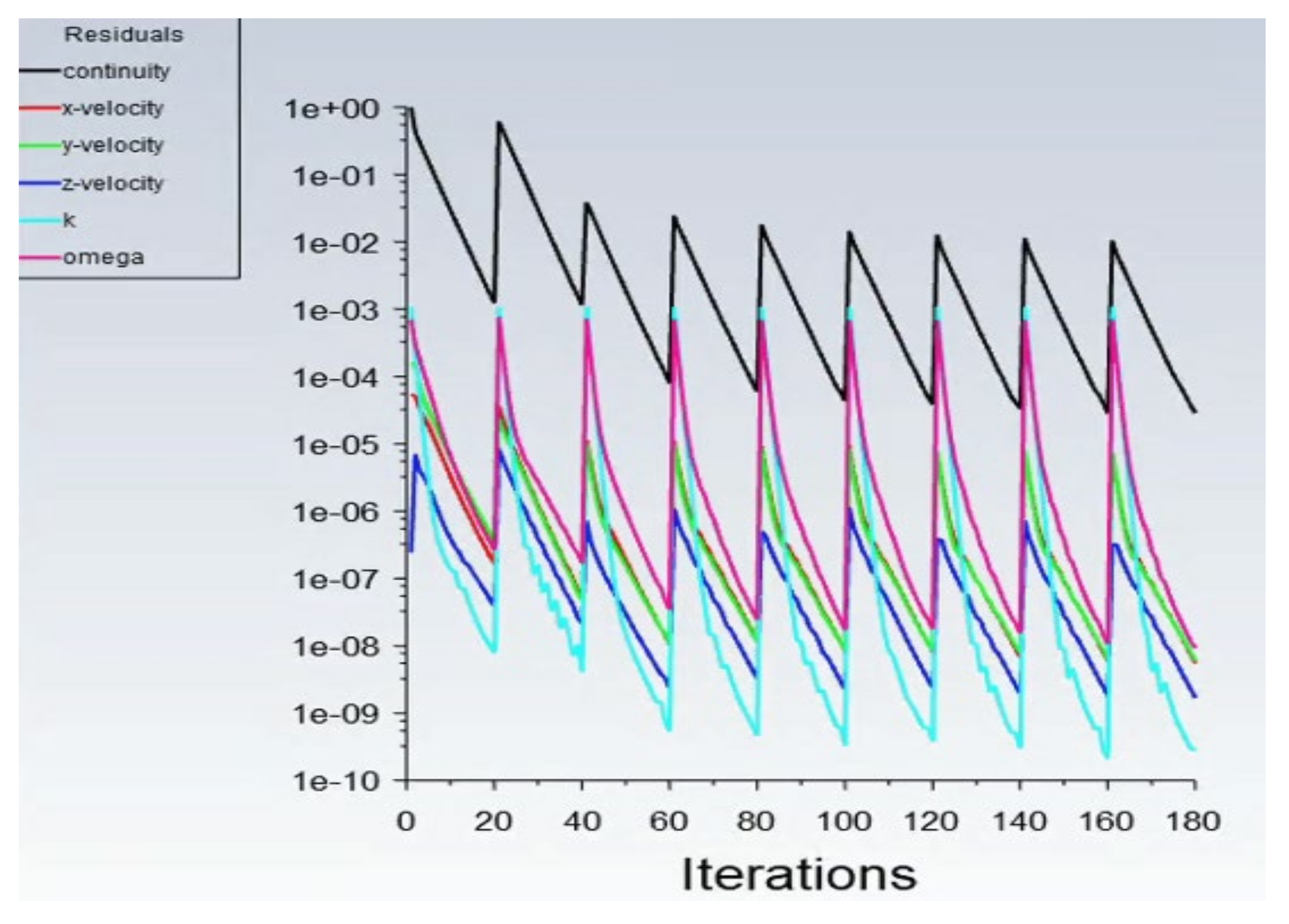
As the product of discretization in the computational domain, mesh serves as the basis of discretization. The quality of meshing not only directly relates to the stability, convergence and computational efficiency of numerical computation, but is also critical to the correctness, resolution and success of the model computation results. In this study, polyhedral mesh (Poly-Hexcore), with hexahedrons as the core, was used to carry out meshing for the computational domain to enable its randomized data structure to more effectively adapt to the mesh, so as to better capture the physical properties of the flow field. A finite volume method featuring the CC (cell center) was utilized to discretize the three-dimensional Navier-Stokes equation, and the Simple algorithm, featuring pressure–velocity coupling, was utilized to solve the discrete equations. When the residual of a certain physical quantity was less than 1 × 10⁻⁶, and all the simulated variables remained basically constant over time, the computation was considered to be convergent, the iteration was stopped, and the computation task was completed and the process ended.

2.3. Model Verification

As it is complicated to obtain experimental measurements and verification data for single-raft aquaculture from a flume experiment, the following two examples with both theoretical solutions and measured values were used to verify the numerical multiphase flow model described in this paper.

2.3.1. Oblique Hydraulic Jumps

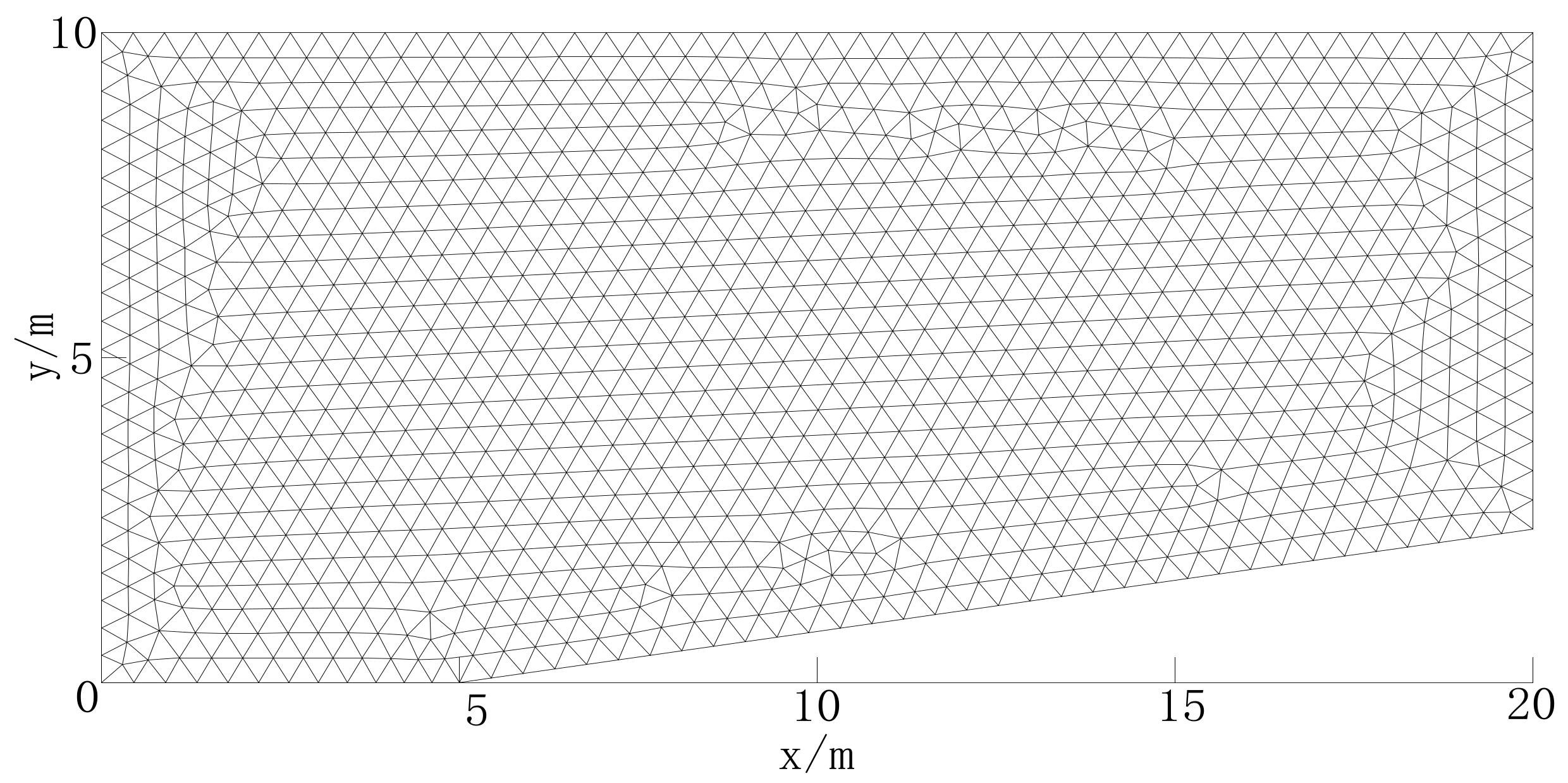
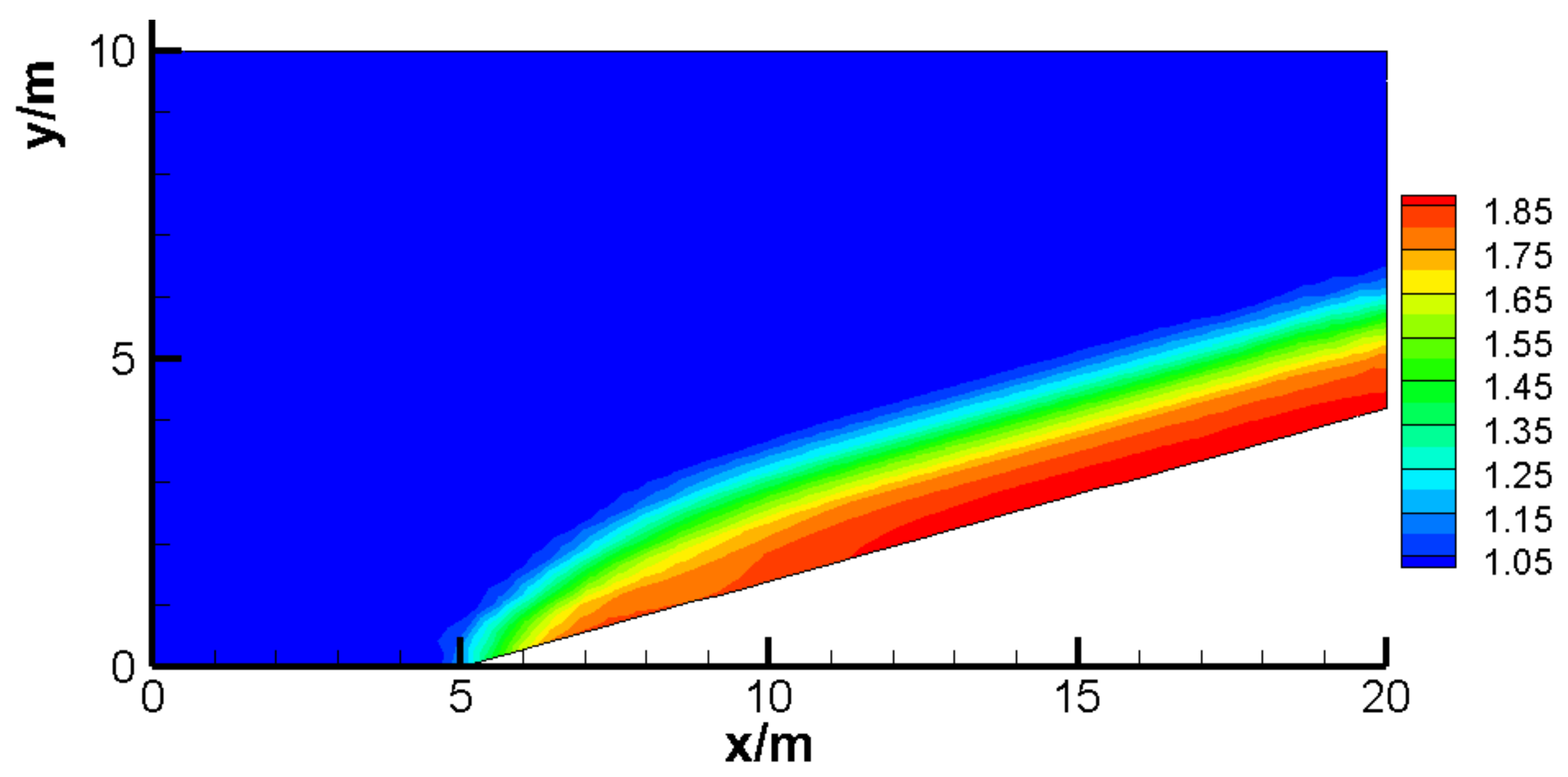
Oblique hydraulic jumps have often been used to test the performance of the computational format of a model. Gas–liquid two-phase flows were used to verify the multiphase flow model described in this paper. Chow obtained a theoretical solution to the problem of oblique hydraulic jumps [28,29]. The model had a computational domain length of 20 m and an upstream channel width of 10 m, which started to narrow at α = 8.95° and at a distance of 5 m from one side of the channel; that is, the downstream channel width was 7.6389 m. The specific computational domain plane is shown in Figure 1. As for the meshing of the computational domain, an unstructured triangular mesh composed of 1275 nodes and 2237 cells was adopted, as shown in Figure 2. The rapid flow boundary conditions were used at the inflow, where h = 1.0 m, and the flow velocity in the direction of x was u = 9.0 m/s; free outflow boundary conditions were used at the outflow, and rigid boundary conditions were adopted for both shorelines. The simulated values were βnumerical = 30° and hnumerical = 1.55 m, and the water flow velocity was Unumerical = 8.34 m/s. The results of the water level simulation are shown in Figure 3. As shown, the simulation results are in good agreement with the theoretical solution (under the given boundary conditions, the theoretical solution to Chow’s oblique hydraulic jump problem is βtheoretical = 29.4, htheoretical = 1.55 m and Uanalytical = 8.34 m/s.), reflecting the accuracy and stability of the multiphase flow model described in this paper.

2.3.2. Passage of Generated Waves through a Submerged Bar

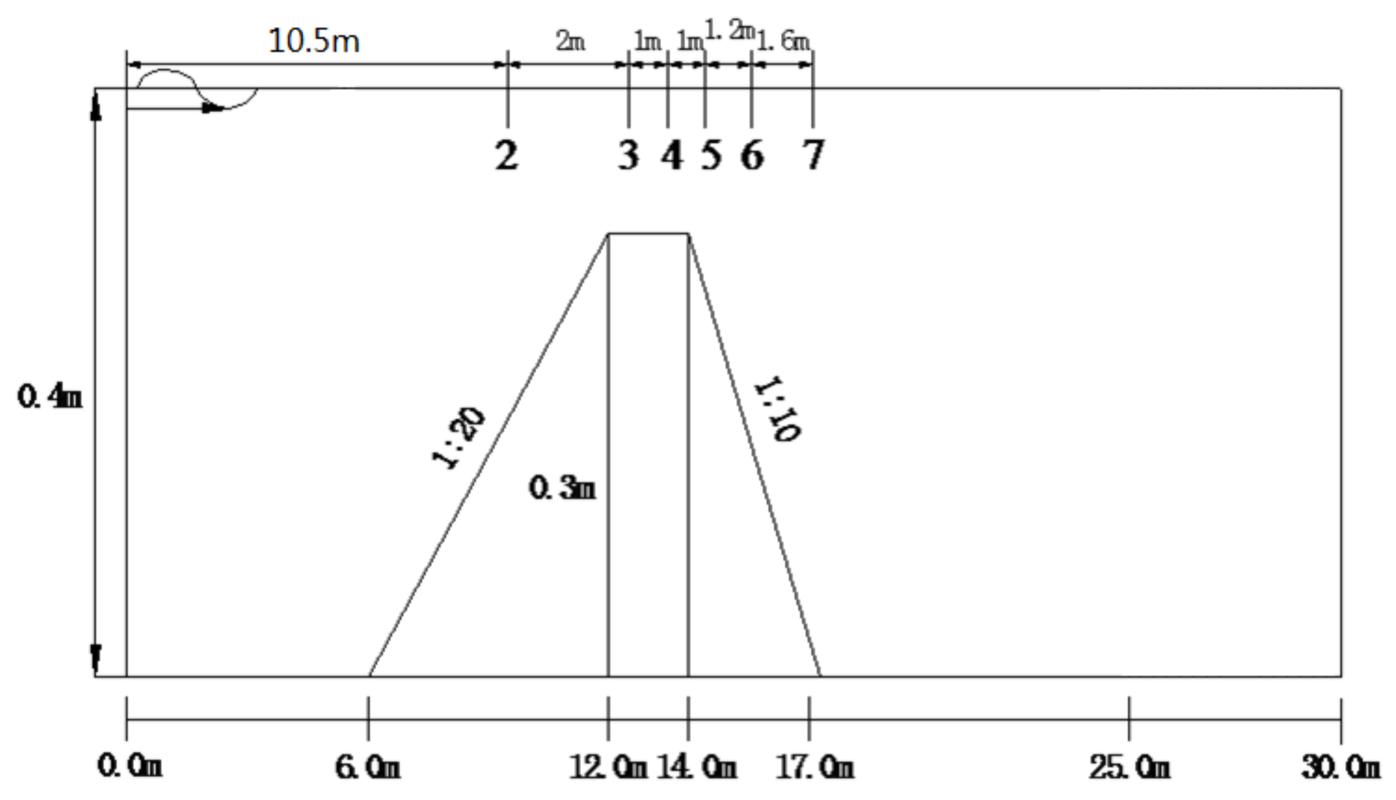
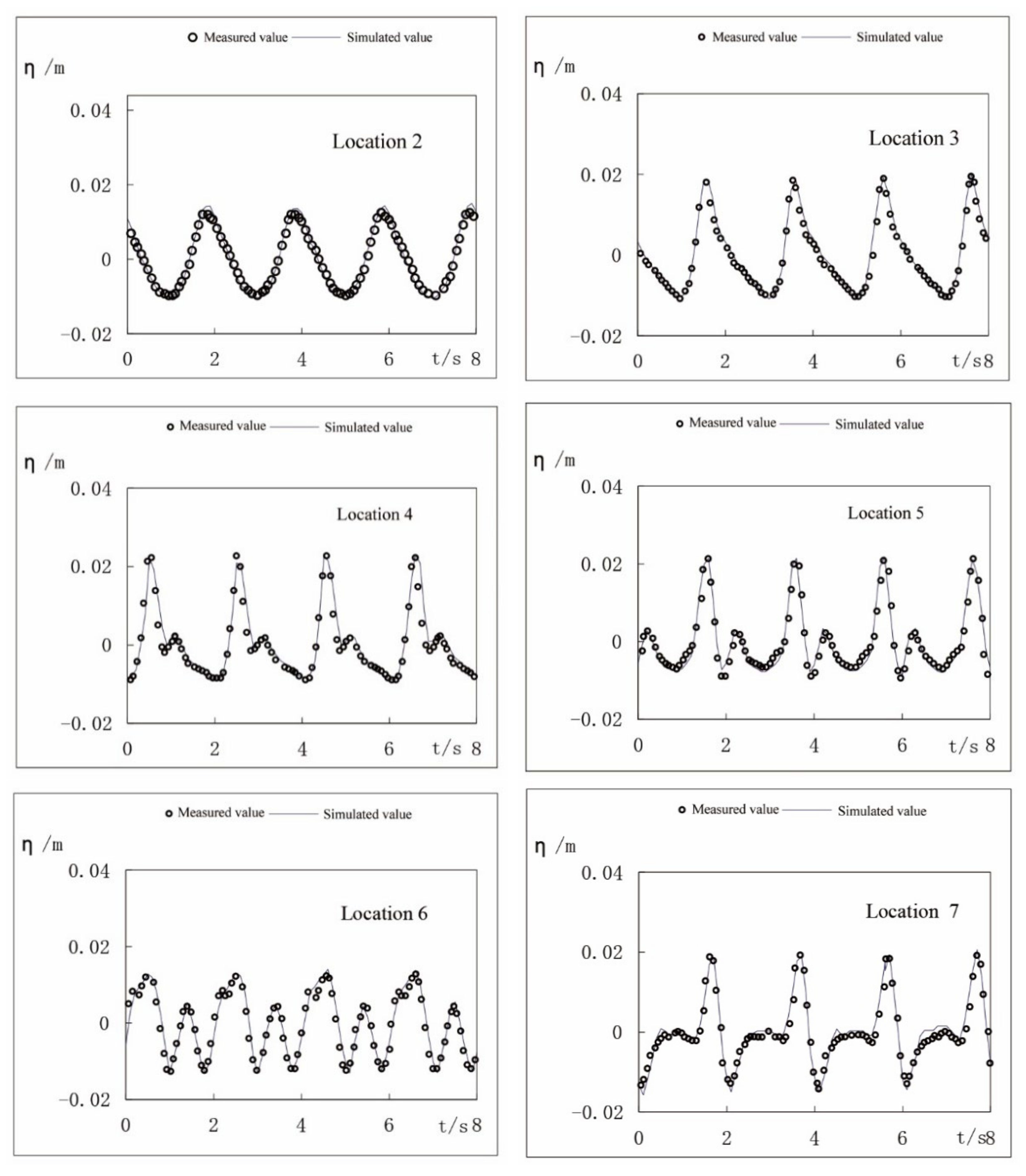
To verify the numerical model described in this paper and thus to calculate the deformation of periodic incident waves passing through a submerged bar during propagation, we used the test settings and model definitions described in a study by Casulli [30]. A schematic diagram of the computational domain and the arrangement of measuring points are shown in Figure 4, where the total length is shown to be L = 30 m, and the static water level is h = 0.4 m. For the inflow, the flow velocity boundary conditions of a regular periodic incident wave are given, where the wave height is H = 0.02 m and the cycle is T = 2.0 s. Figure 5 shows comparisons between the simulated and measured values of the water level at six gauge locations, indicating that the two are in good agreement, which reflects the great performance of the model described in this paper in the simulation for the problem concerning gas–liquid two-phase flows caused by inflow waves.

2.4. VOF Multiphase-Flow Simulation of Water Flow Movement via a Single Floating Raft Aquaculture Structure

2.4.1. Modeling

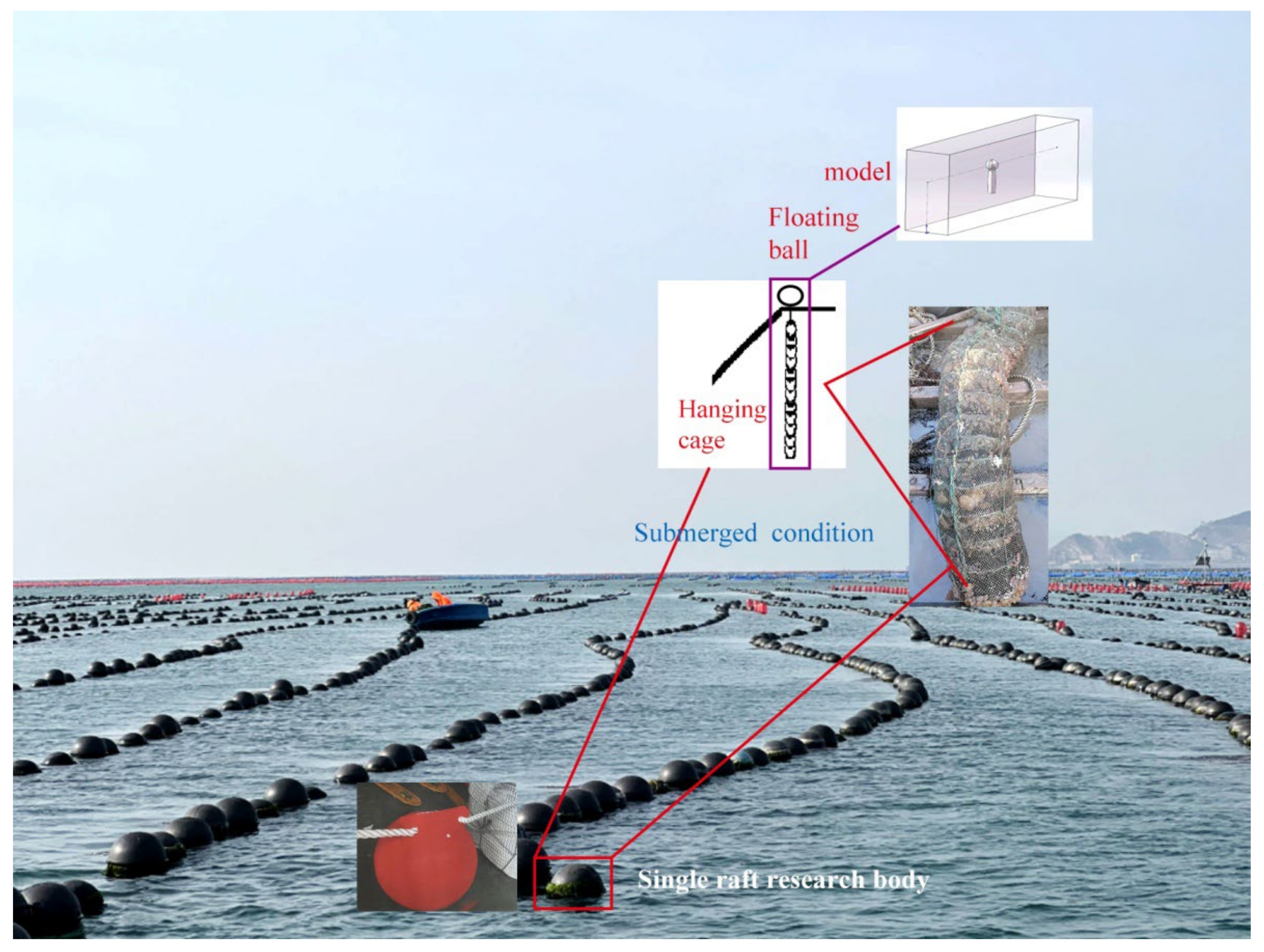
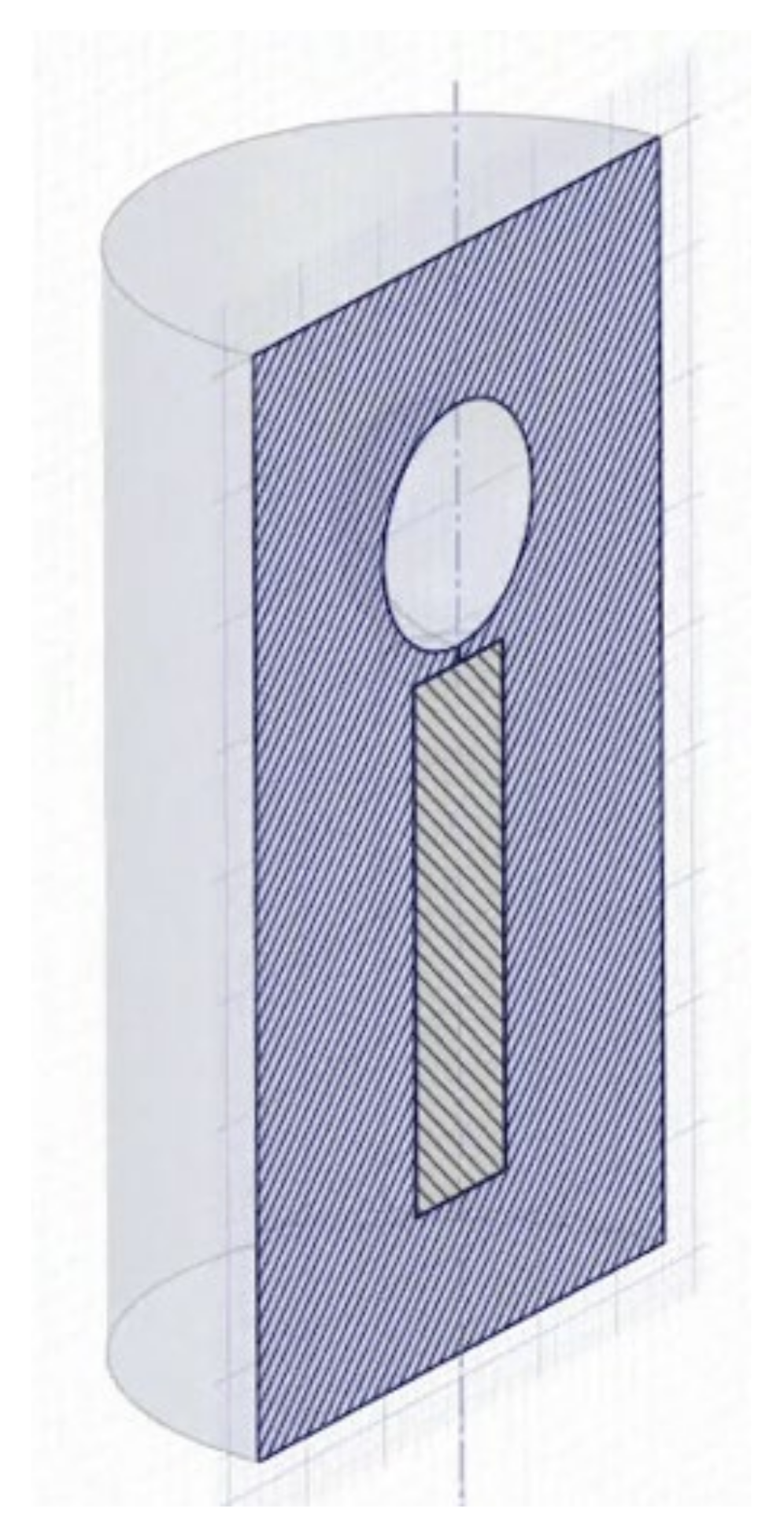
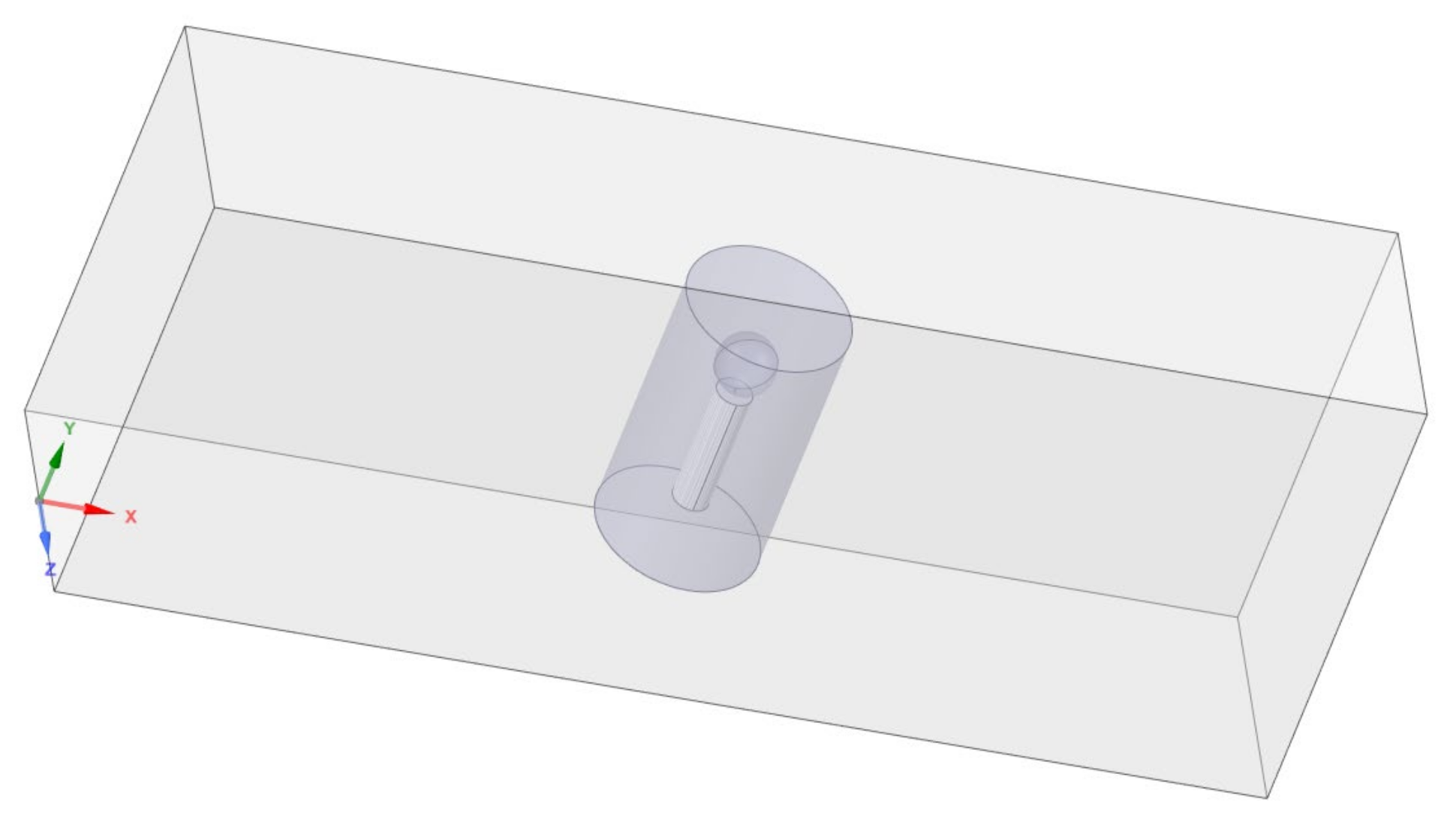
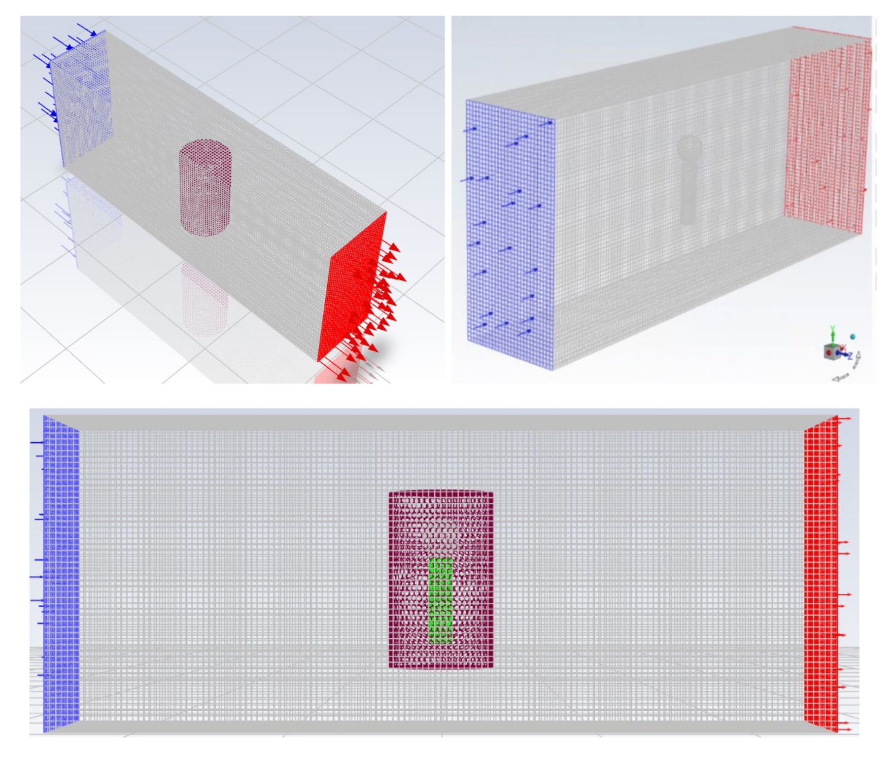
Solid Works [31] is a 3D modeling software package featuring easy operation and flexibility, being an easy-to-use parameterization and solid modeling design tool developed on the basis of Windows. It was used for early modeling in the aquaculture example from this raft area, as shown in Figure 6 below. The idea of adding overlapping areas was introduced to lay a foundation for the later multiphase simulation. In this paper, the small part of the peripheral waters is referred to as the computational domain of the background, and the hanging cage (net cage), floating ball and overlapping area of the aquaculture facility are referred to as the computational domain of the components. The schematic diagram of the cross-section in the body is shown in Figure 7, and the final complete model establishment is shown in Figure 8.

2.4.2. Meshing

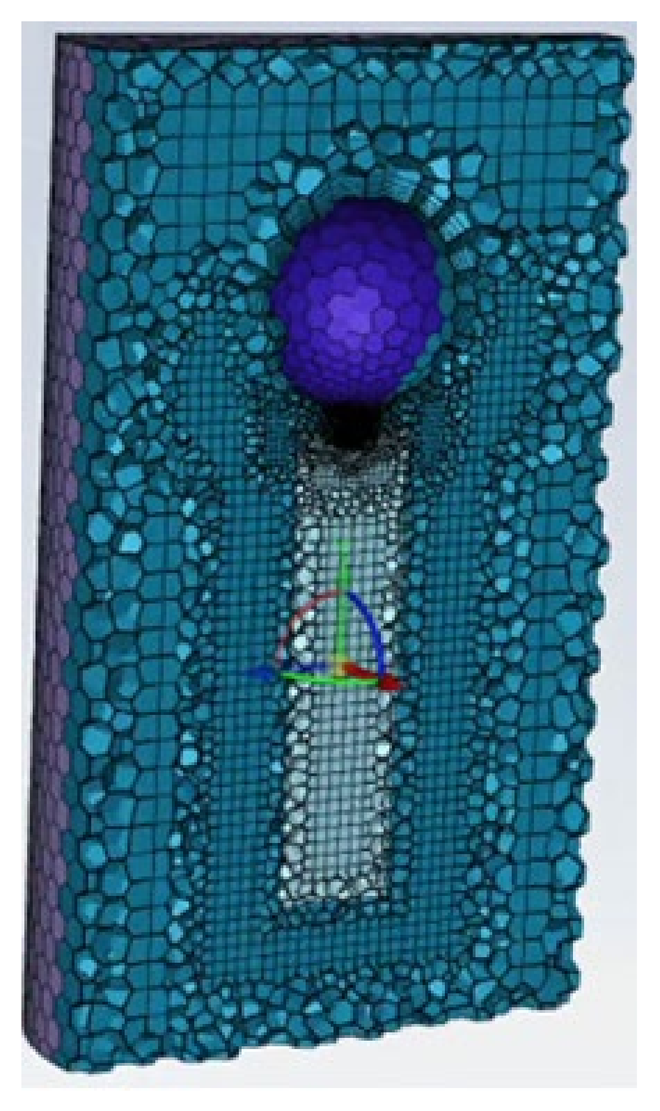
The computational domain of the background in the model was subject to structured meshing with the software ICEM (https://www.3ds.com/products-services/catia/products/icem-surf/, accessed on 25 September 2023), and unstructured meshing was performed for the components based on the FLUENT Mesh platform, wherein the component mesh was divided into the computational domain of the overlapping area and the internal computational domain, and the mesh structure relationship between the two parts of the computational domain was a shared topology. This was carried out with the aim of increasing the accuracy of the numerical simulation computation. Figure 9 shows the generated component surface mesh and section mesh, including overlapping cells, where the largest mesh scale was 75 mm, the smallest mesh scale was 1 mm and the gradient growth rate was 1.2. When the meshes were refined based on a curvature of 20, the number of generated surface cells was 9716, and the component part was divided into polyhedral mesh (Poly-Hexcore) cells featuring a uniform transition through three-dimensional division, wherein a hexahedron served as the core. As shown in Figure 10, the number of cells was 106,642. Such volume meshes have great advantages in controlling the computation load. As for the meshing of the computing domain of the background, the maximum mesh scale was also set to 0.075 m, the same as that of the component part, as shown in Figure 11. The cell distribution of the 3D volume mesh is shown in Figure 12, and the number of cells was 195,372. A large increase in the number of cells in pure 3D volume meshes tends to happen, and huge-volume mesh systems challenge the performance of both the program and the machine.

2.4.3. Setting of Boundary Conditions and Parameters

At the beginning of the computation, the “cold position” was used, for which the initial values of all physical quantities were set to 0. Relative to the computational domain of a single raft, including the surrounding sea area, the left boundary was set to the inlet of generated waves, the bottom boundary and the four-side solid boundary were set to solid boundary conditions without slip and the upper outlet boundary was connected to the atmosphere. It was assumed that there was no shear or slip velocity on the water surface, so it could be treated as a free surface and set to a pressure outlet, and the pressure value was set to a standard atmospheric pressure.

2.4.4. Model Computation Results

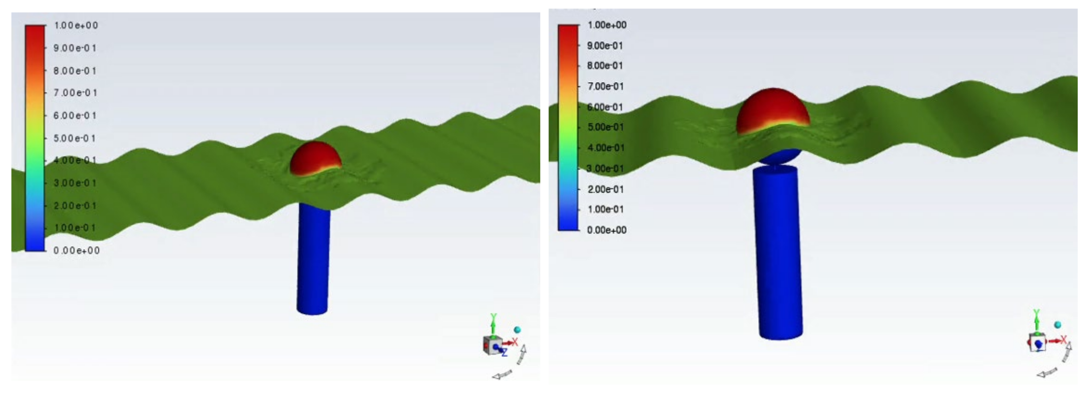
Based on the overset dynamic mesh, the VOF multiphase flow module was used to numerically simulate the water flow movement surrounding a single floating raft aquaculture facility. The impact on the raft or the cage was considered with a porous jump model; by setting the moment of inertia of the floating facility, the state of motion of the floating ball could be truly reflected. The computation results are shown in Figure 13 below. During the computation process, the residual curve distribution graph served as a main index for determining the degree of convergence of the model, and its changes over time are shown in Figure 14.

3. Impact of Floating Raft Aquaculture on the Hydrodynamic Environment of the Sea Area in Changhai County, Dalian

3.1. Quantitative Description of the Impact of the Resistance from Aquaculture on the Entire Floating Raft Aquaculture Area

For a 5000-acre floating raft aquaculture area, based on the HYDROINFO platform developed by the Computational Hydraulics Laboratory of Dalian University of Technology, we considered the impact of floating rafts on the hydrodynamic force in each cell by adding the following source term to the momentum equation [27]:
S = 0.5 ρ C u 2 A V
where S is the source term of the momentum equation, A is the flow-facing area of the floating raft, C is the resistance coefficient of the floating raft aquaculture facility and V is the volume of the computing unit.

3.2. Meshing and Other Parameter Settings

Meshing of the large-scale computational domain was carried out with unstructured triangular mesh cells, wherein the number of nodes was 71,259, the number of cells was 140,125, the minimum meshing scale was 30 m and the simulation time step was 1800 s. At the beginning of the computation, the “cold position” was used, wherein the initial values of all physical quantities were set to 0. The open boundary was driven by the time-series conditions of tide levels obtained with the tidal harmonic analysis method.

3.3. Hydrodynamic Model Verification

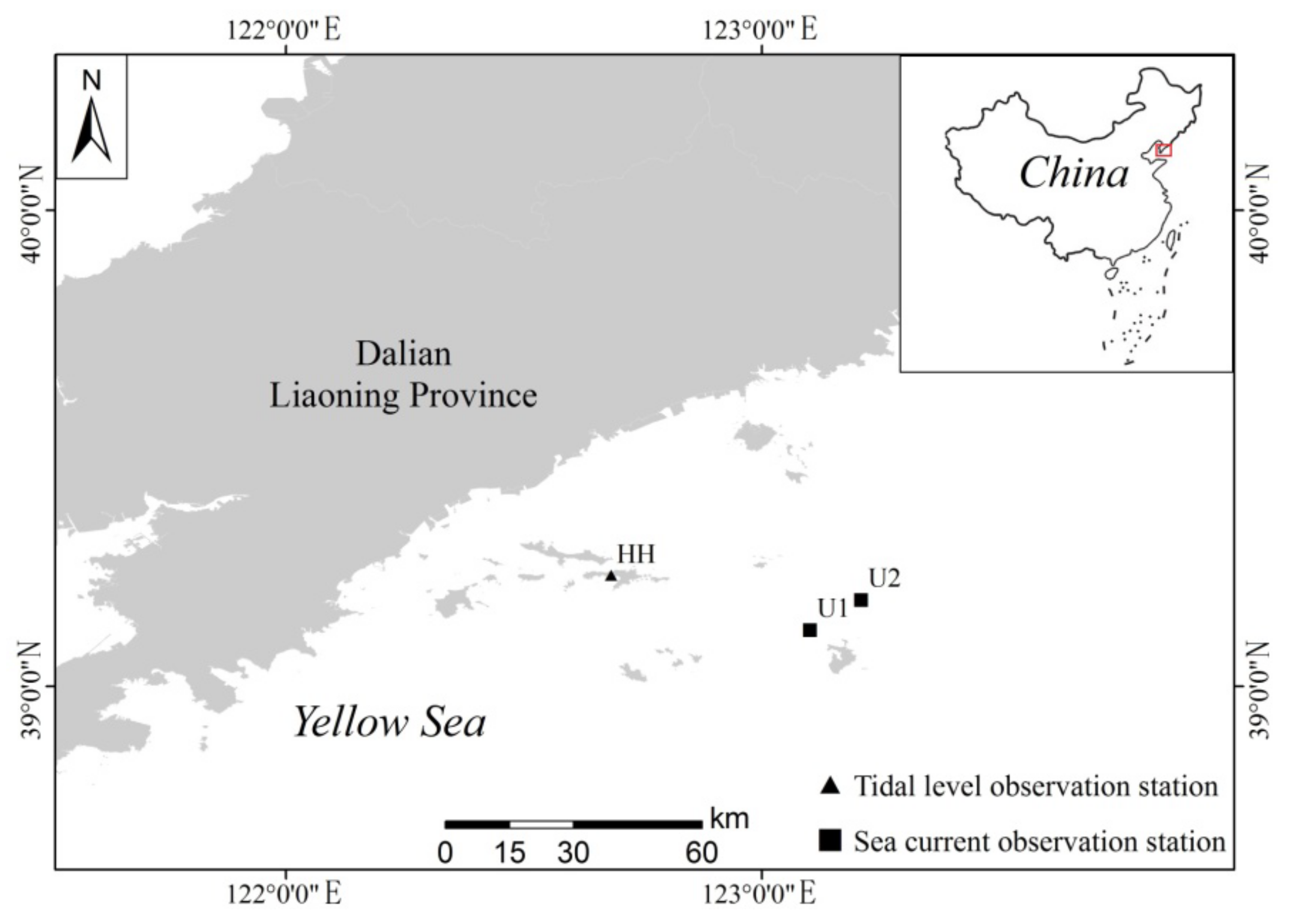
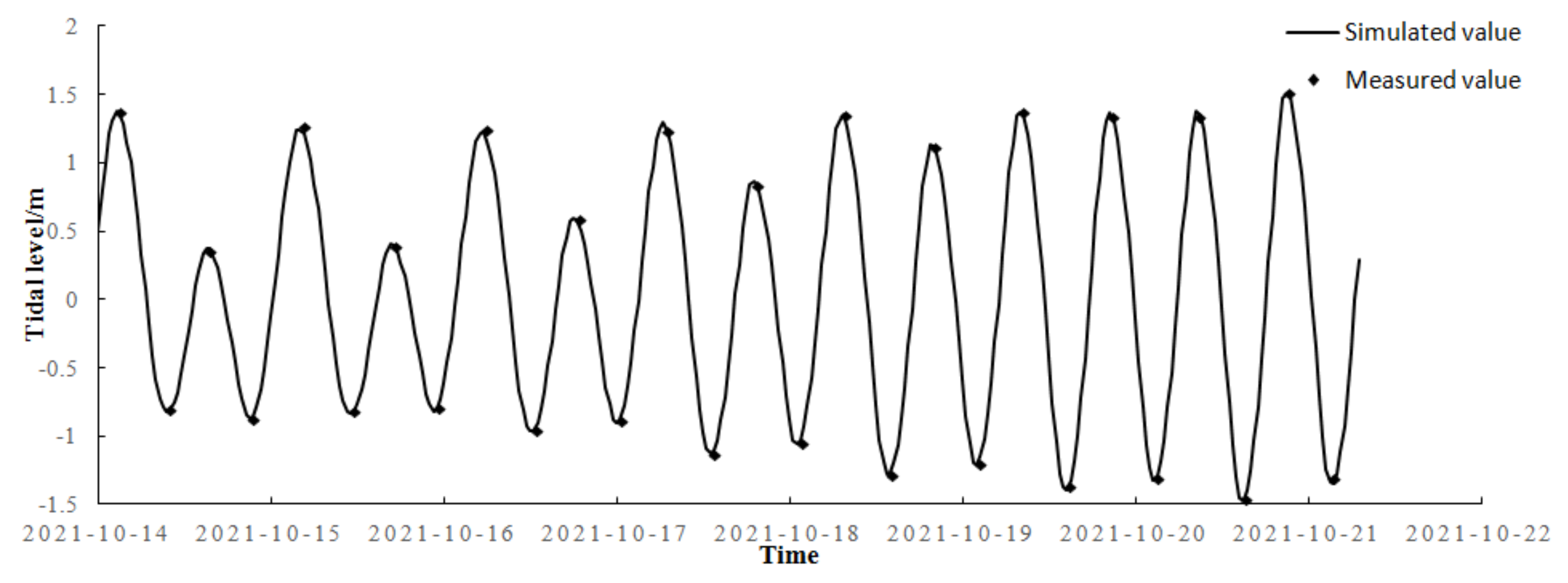
In 2021, tide levels and ocean currents were continuously observed in the waters near Changhai County, Dalian. The coordinates and locations of the observation stations are shown in Table 1 and Figure 15 below. The verification results are shown in Figure 16 and Figure 17.

3.4. Simulation and Prediction Results

In order to fully present the simulation results for the numerical model, the hydrodynamic field distribution results at high tide and low tide without and with floating rafts at a depth of 0.6 × water depth are shown in Figure 18 and Figure 19.

3.5. Analysis of Model Accuracy

In order to verify the accuracy of the model, the relative error between the simulated values and the measured values was quantitatively analyzed with the relative standard deviation. The RSD value represents the relative standard deviation between the results from the model and the measured data. The computation expression of RSD is described below:
R S D = i = 1 n S i M i 2 n 1 M ¯ × 100 %
where Si represents the simulated value, Mi represents the measured value, n is the number of values, and M ¯ represents the average of the measured values. After calculation, it was found that the relative standard deviation of the current velocity at the ocean current observation stations was less than 5%. The mean absolute error of tide levels at the tide observation stations was less than 8 cm, showing that the model has great accuracy.

4. Simulation Results of Water Exchange Performance and Analysis

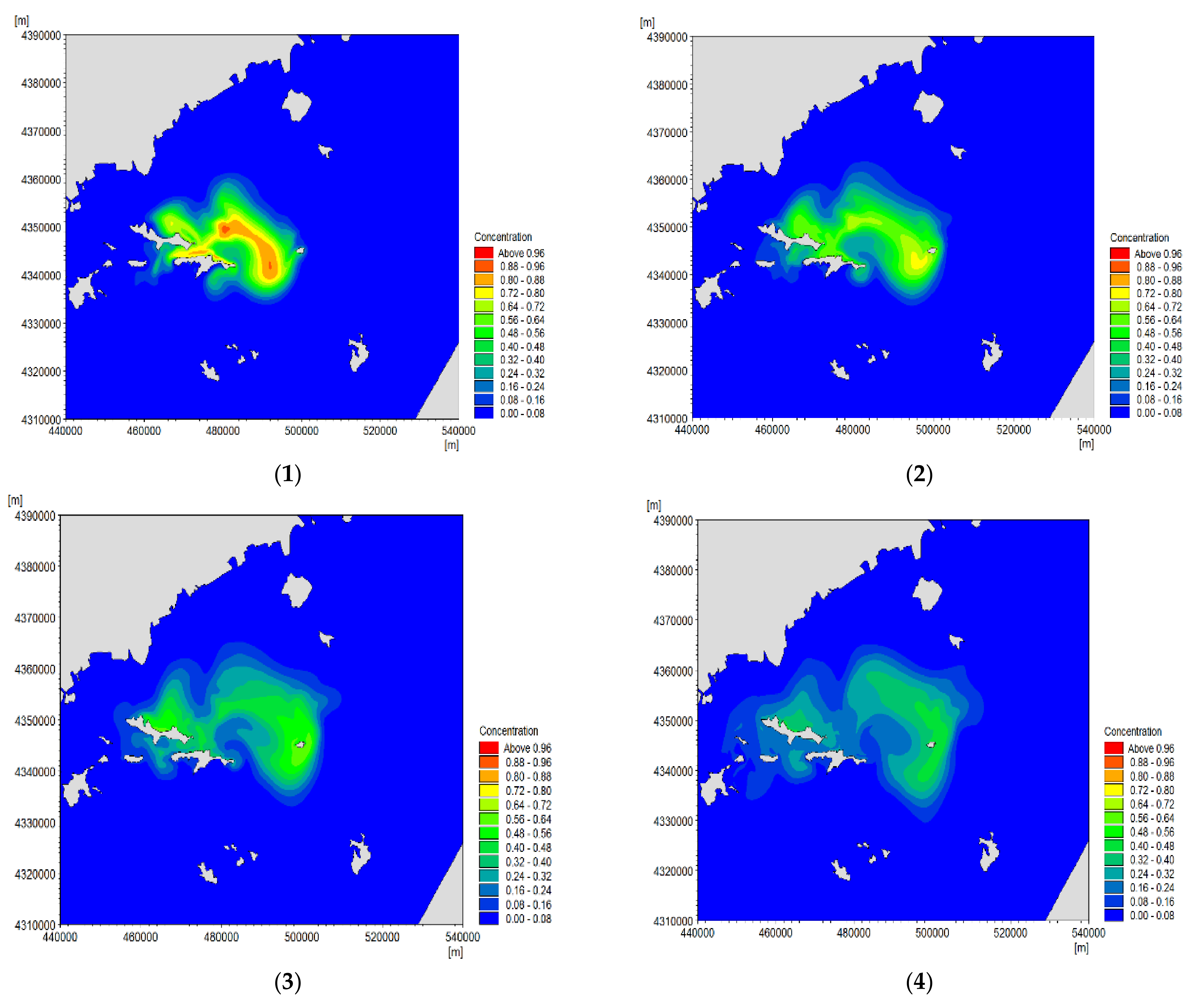
Against the backdrop of the computed hydrodynamic force results and considering the resistance from the entire raft area, the water exchange performance of a nearby large-scale sea area was simulated. As for the simulation of the water exchange degree, the aforesaid transport equations, in combination with the tracer method [21], were used for computation, evaluation and description, and a comparative analysis of water exchange rates in the natural sea area and the sea areas near the floating raft aquaculture area was carried out. Figure 20 shows the distribution of substance transport and diffusion concentration fields at different times (2d, 4d, 6d and 8d) after the implementation of aquaculture activities. Table 2 describes the statistics of water exchange rates over time with and without floating raft aquaculture.

5. Results and Discussion

5.1. Analysis of Calculation Results of a Single Raft

(1)
The hydrodynamic force calculation results for a single raft in the aquaculture area show that based on a comparison between the distribution of the water level simulation results and that of the results for the raft aquaculture area, the mean water level in the raft aquaculture area was reduced by 1.05 cm compared to the mean water level in the corresponding sea area before aquaculture; the water level was reduced by at least 5.97 cm, the degree of reduction was up to about 5% and the mean flow velocity decreased by 5.24 cm/s, which indicates that this working condition was just a scenario of inflow wave generation and did not significantly affect the hydrodynamic force surrounding the raft.
(2)
The given flow velocity boundary of the inflow was 50 cm/s, and the other calculation conditions remained unchanged. Due to the limited space, the calculation results and analysis are described here. After the centroid of the physical structure was extracted, the mean flow velocity [27] at a distance of 2.5 m was 32.7 cm/s, and the flow resistance rate of a single raft was about 35% according to the calculation results. The quantitative parameter that reflected the impact of the raft area on the hydrodynamic force could be applied to the entire aquaculture area.

5.2. Analysis of Calculation Results of the Floating Raft Aquaculture Area

(1)
We quantitatively analyzed the relative error between the simulated values and the measured values by comparing them and using the relative standard deviation. It was found that the relative standard deviation of flow velocity was less than 5% and the average absolute error of tide level was less than 8 cm, indicating that the model has great accuracy, which further demonstrates that the VOF multiphase flow model used in this study accurately depicts the resistance from the facility in an aquaculture area with a single floating raft, and this quantitative damping result can be applied to large-scale simulations for actual raft areas. These results show that the simulated values are in good agreement with the measured values, which demonstrates that the model is relatively reliable.
(2)
According to the simulation results for the water exchange rate shown in Table 1, after 1 d, 5 d and 9 d of water exchange, the water exchange rates were 27.90%, 64.65% and 80.26%, respectively, when there was no floating raft, and 22.21%, 57.84% and 76.87%, respectively, when there were floating rafts, a decrease of 5.69%, 6.81% and 3.39%, respectively. The half-exchange cycles without and with floating raft aquaculture appeared on 2.3 d and 3.99 d, respectively, showing that the water exchange rates in a sea area with floating raft aquaculture were significantly reduced compared with those in a natural sea area.

6. Conclusions

In this study, based on a six-degree-of-freedom overset polyhedral (Poly-Hexcore) mesh system, a three-dimensional VOF multiphase flow model was used to simulate the impact of a floating raft for aquaculture on the hydrodynamic environment and water exchange performance surrounding the aquaculture area. This study shows that the VOF multiphase flow model can be easily and accurately applied to studies on floating raft aquaculture, which can greatly reduce the limitations of those experiments that utilize pure hydraulic models wherein the impacts of floating raft aquaculture facilities on hydrodynamic force are generally considered based on observations, water roughness or the secondary drag force coefficient alone, thereby effectively improving the scientific understanding of the physical mechanism involved in floating raft aquaculture and providing technical support for the rational arrangement of aquaculture orientations and the scientific setting of aquaculture density.
(1)
Based on spatial modeling, wherein the impact of the floating raft facility, mainly including the floating ball, the external aquaculture net of the hanging cage and organisms, was considered, the computation results for the flow of water through a single raft show that the 3D VOF multiphase flow model described in this paper can accurately simulate the flow of water through the raft and the hydrodynamic environment of the raft aquaculture area, which demonstrates great stability and universality.
(2)
When the hydrodynamic force results calculated using the 3D VOF multiphase flow model were used as the background conditions, the convection–diffusion tracer method based on Euler substance transport was used to quantitatively calculate the water exchange rates in the fixed aquaculture area for statistics, which indicates that the aquaculture activities have significantly reduced the water exchange rates in this open-sea area during different periods. In addition, the half-exchange cycles of the water further showed that the existence of floating raft aquaculture activities has reduced the water exchange performance of this sea area. The exact extent of this impact depends on the density, size, scope and location of rafts in an aquaculture area.
(3)
Even floating raft aquaculture facilities located in open-sea areas, such as the sea area in Changhai County, have a certain impact on water exchange performance, and the specific extent of this impact varies with the density, size, scope and location of rafts in the aquaculture area, which should absolutely be brought to the attention of workers engaging in fishery, aquaculture and marine environment protection. In addition, only after accurately determining the impact of a raft area on the hydrodynamic environment can aquaculture workers select a reasonable site and install bait feeding and distribution devices in an area where biological nutrients are scarce, thereby helping increase the yield and efficiency of raft aquaculture, ensuring stable income for aquaculture operators and improving the social and economic benefits provided by the floating raft aquaculture areas in Changhai County and other open-sea floating raft aquaculture areas.
(4)
In future studies, the law of flow velocity attenuation in the downstream area for floating rafts should be considered when cages and the water flow direction are at different angles of attack. Furthermore, in addition to the impact of floating rafts in aquaculture facilities on the hydrodynamic force, the impact of cultured organisms in hanging cages and the biomasses of different aquaculture cycles on the hydrodynamic environment should also be taken into account. Such studies would further provide technical methods for the precise layout of actual raft areas and technical support for the development of the industry.

Author Contributions

Conceptualization, K.W. and L.S.; methodology, K.W. and H.J.; software, K.W. and H.J.; validation, K.W., H.J. and J.W.; formal analysis, N.L.; resources, K.W.; data curation, K.W. and L.S.; writing—original draft preparation, K.W.; writing—review and editing, K.W., H.J. and N.L.; supervision, K.W., L.S. and J.W.; project administration, L.S. and J.W.; funding acquisition, J.W., N.L. and L.S. All authors have read and agreed to the published version of the manuscript.

Funding

Science and Technology Innovation Fund Program of Dalian (2022JJ13SN065); Key Laboratory of Environment Controlled Aquaculture (Dalian Ocean University) Ministry of Education (grant number 202217); The applied basic research plan of Liaoning Province, China (2022JH2/101300176); Special Program for Marine Economic Development of Liaoning Province.

Data Availability Statement

This research did not report any data that are linked to publicly archived datasets analyzed or generated during the study.

Conflicts of Interest

No potential conflicts of interest were reported by the authors. The funders had no role in the design of the study; in the collection, analyses, or interpretation of data; in the writing of the manuscript, or in the decision to publish the results.

References

  1. Gao, J.; Lyu, J.; Wang, J.; Zhang, J.; Liu, Q.; Zang, J.; Zou, T. Study on transient gap resonance with consideration of the motion of floating body. China Ocean Eng. 2022, 36, 994–1006. [Google Scholar] [CrossRef]
  2. Weng, L.X.; Xu, J.N.; Hu, Z.X. Analysis and Evaluation of Wind Turbine Flow Field and Noise Simulation Based on CFD Software. Appl. Mech. Mater. 2014, 716–717, 755–759. [Google Scholar] [CrossRef]
  3. Gao, J.; Shi, H.; Zang, J.; Liu, Y. Mechanism analysis on the mitigation of harbor resonance by periodic undulating topography. Ocean Eng. 2023, 281, 114923. [Google Scholar] [CrossRef]
  4. Sharma, S.L.; Ishii, M.; Hibiki, T.; Schlegel, J.P.; Liu, Y.; Buchanan, J.R., Jr. Beyond Bubbly Two-Phase Flow Investigation using a CFD Three-Field Two-Fluid Model. Int. J. Multiph. Flow 2019, 113, 1–15. [Google Scholar] [CrossRef]
  5. Gao, J.; He, Z.; Huang, X.; Liu, Q.; Zang, J.; Wang, G. Effects of free heave motion on wave resonance inside a narrow gap between two boxes under wave actions. Ocean Eng. 2021, 224, 108753. [Google Scholar] [CrossRef]
  6. Gao, J.; Ma, X.; Dong, G.; Chen, H.; Liu, Q.; Zang, J. Investigation on the effects of Bragg reflection on harbor oscillations. Coast. Eng. 2021, 170, 103977. [Google Scholar] [CrossRef]
  7. Jalaluddin, M.I. CFD Simulation of 3-D Flow Field over Clean and Loaded Wing; Universiti Teknologi Petronas: Perak, Malaysia, 2014; pp. 1–30. [Google Scholar]
  8. Aly, E.A.; Habashi, W.G. Accurate marine propellers flow field CFD through anisotropic mesh optimization. Int. J. Numer. Methods Heat Fluid Flow 2019, 29, 3148–3168. [Google Scholar]
  9. Xie, H.; Yang, J.; Hu, Y.; Zhang, H.; Yang, Y.; Zhang, K.; Zhu, X.; Li, Y.; Yang, C. Simulation of flow field and sludge settling in a full-scale oxidation ditch by using a two-phase flow CFD model. Chem. Eng. Sci. 2014, 109, 296–305. [Google Scholar] [CrossRef]
  10. Yang, Y.; Li, D.; Ma, Y.; Zhang, M. Refinement three-dimensional simulation of effect of floodplain vegetation on hydrodynamic characteristics in compound open channel based on Fluent soft ware. J. Dalian Ocean Univ. 2021, 36, 317–324. [Google Scholar]
  11. Gallerano, F.; Cannata, G.; Barsi, L.; Scarpone, S. Numerical Investigation of Fluid-Structure Interaction for Long-Span Bridge Decks; WIT Press: Torquay, UK, 2016; Volume 105, pp. 15–26. [Google Scholar]
  12. Hessenthaler, A.; Roehrle, O.; Nordsletten, D. Validation of a non-conforming monolithic fluid-structure interaction method using phase-contrast MRI. Commun. Numer. Methods Eng. 2017, 33, e2845. [Google Scholar] [CrossRef]
  13. Lindgren, J.; Karlsson, H. Fluid-Structure Interaction; Numerical Modelling and Experimental Comparison. Struct. Mech. 2017, 3–49. [Google Scholar]
  14. Habeeb, L.J.; Saleh, F.A.; Maajel, B.M. Numerical Simulation of 3-D One-Way Fluid-Structure Interaction in a Tube with Twisted Tape under Laminar and Turbulent Flow Regime. Int. J. Appl. Eng. Res. 2018, 13, 1–10. [Google Scholar]
  15. Sangalli, L.A.; Braun, A.L. A fluid-structure interaction model for numerical simulation of bridge flutter using sectional models with active control devices. Preliminary results. J. Sound Vib. 2020, 477, 115338. [Google Scholar] [CrossRef]
  16. Kassiotis, C.; Ibrahimbegovic, A.; Matthies, H. Partitioned solution to fluid-structure interaction problems in application to free-surface flows. Eur. J. Mech. B Fluids 2010, 29, 510–521. [Google Scholar] [CrossRef]
  17. He, Y.; Huang, D.; Zeng, D.; Qiao, X. The impact of raft kelp aquaculture on the vertical structure of tidal currents in Sanggou Bay. J. Mar. Sci. 2016, 34, 20–27. [Google Scholar]
  18. Klebert, P.; Su, B. Turbulence and flow field alterations inside a fish sea cage and its wake. Appl. Ocean Res. 2020, 98, 102113. [Google Scholar] [CrossRef]
  19. Ji, R.; Mao, X.; Zhu, M. The impact of shellfish farming on the bay ecosystem. Huanghai Sea Bohai Sea 1998, 16, 21–27. [Google Scholar]
  20. Scott, C.; James, F.O. Drag coefficient parameter estimation for aquaculture systems. Environ. Fluid Mech. 2019, 19, 989–1003. [Google Scholar]
  21. Wang, K.; Li, N.; Wang, Z.; Song, G.; Du, J.; Song, L.; Jiang, H.; Wu, J. The Impact of Floating Raft Aquaculture on the Hydrodynamic Environment of an Open Sea Area in Liaoning Province, China. Water 2022, 14, 3125. [Google Scholar] [CrossRef]
  22. Zhang, Z.; Huang, H.; Liu, Y.; Bi, H.; Yan, L. Numerical study of hydrodynamic conditions and sedimentary environments of the suspended kelp aquaculture area in Heini Bay. Estuarine. Coast. Shelf Sci. 2020, 232, 106492. [Google Scholar] [CrossRef]
  23. ANSYS, Inc. ANSYS Fluent Theory Guide; ANSYS: Canonsburg, PA, USA, 2018. [Google Scholar]
  24. Wang, K.; Jin, S.; Liu, G. Numerical modelling of free-surface flows with bottom and surface-layer pressure treatment. J. Hydrodyn. 2009, 21, 352–359. [Google Scholar] [CrossRef]
  25. Salih, S.M.; Jalil, J.M.; Najim, S.I. Experimental and numerical analysis of a double-pass solar air heater with PCM. Renew. Energy 2019, 143, 1053–1066. [Google Scholar] [CrossRef]
  26. Liu, X.; Cheng, L. A K-ε two-equation turbulence model for the solid-liquid two-phase flows. Appl. Math. Mech. 1996, 17, 523–531. [Google Scholar]
  27. Liu, C. Study on Characteristics of Flow Distribution around Marine Cage Culture Area; Tianjin University: Tianjin, China, 2020. [Google Scholar]
  28. Wu, H.; Wang, J. A high-resolution finite volume method for solving two-dimensional shallow water equations. Commun. Appl. Math. Comput. 2006, 20, 83–88. [Google Scholar]
  29. Pan, C.; Xu, K. To solve two-dimensional shallow water equations in the form of KFVS with triangular meshes. J. Hydraul. Eng. 2006, 3, 858–864. [Google Scholar]
  30. Casulli, V. Semi-Implicit Numerical Modeling of Nonhydrostatic Free-Surface Flows for Environmental Problems. Math. Comput. Model. 2002, 36, 1131–1149. [Google Scholar] [CrossRef]
  31. Liu, F.; Huang, K.; Jiang, Y.; Song, S.; Gu, B. Analytical Description for Solid-State Phase Transformation Kinetics: Extended Works from a Modular Model, a Review. J. Mater. Sci. Technol. 2016, 32, 97–120. [Google Scholar] [CrossRef]
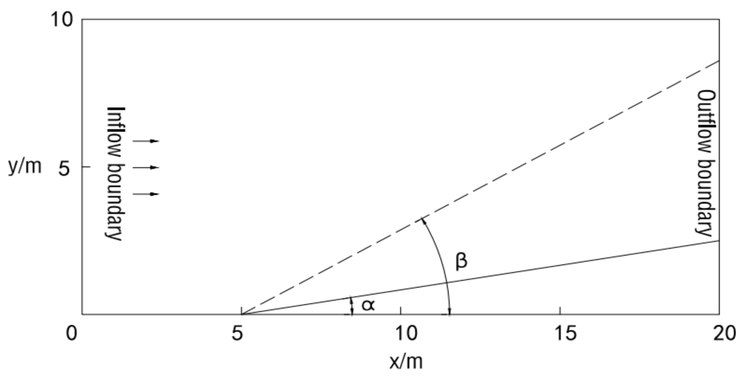
Figure 1. Schematic diagram showing a hydraulic jump.
Water 15 03450 g001
Figure 2. Computed grid.
Water 15 03450 g002
Figure 3. Distribution map of water level results.
Water 15 03450 g003
Figure 4. Geometric modeling construction.
Water 15 03450 g004
Figure 5. Comparisons of the free surface elevation between numerical results and experimental data at six wave gauge locations.
Water 15 03450 g005
Figure 6. Schematic diagram of the actual state of the floating raft aquaculture area.
Water 15 03450 g006
Figure 7. Cross-sectional schematic diagram of the volume center.
Water 15 03450 g007
Figure 8. Schematic diagram of final model.
Water 15 03450 g008
Figure 9. Surface mesh and section mesh of the computational domain of components.
Water 15 03450 g009
Figure 10. Distribution of the 3D mesh of the computational domain of components.
Water 15 03450 g010
Figure 11. Distribution of the 3D mesh of the computational domain of the background.
Water 15 03450 g011
Figure 12. Overall grid distribution diagram of the model.
Water 15 03450 g012
Figure 13. The results for interactions between a single floating raft facility for aquaculture and the water body (t = 1 s, 1 min).
Water 15 03450 g013
Figure 14. Residual curve distribution plots (1e − a = 1 × 10−a; 1 × 100 = 1.0).
Water 15 03450 g014
Figure 15. Distribution of locations of observation stations.
Water 15 03450 g015
Figure 16. Tide level verification results.
Water 15 03450 g016
Figure 17. Ocean current verification results.
Water 15 03450 g017
Figure 18. Hydrodynamic field distribution results at low tide (left) and high tide (right) without floating rafts.
Water 15 03450 g018
Figure 19. Hydrodynamic field distribution results at low tide (left) and high tide (right) with floating rafts.
Water 15 03450 g019
Figure 20. Distribution of water quality–tracer concentration diffusion over time after the implementation of aquaculture activities (2d-(1), 4d-(2), 6d-(3) and 8d-(4)).
Water 15 03450 g020
Table 1. Coordinates of the hydrometric stations for hydrological tide tests.
StationLongitudeLatitude
HH122°41.000′ E39°14.000′ N
U1123°06.098′ E39°07.111′ N
U2123°12.539′ E39°10.895′ N
Table 2. Statistics of water exchange rates over time in a natural sea area and a sea area with floating rafts.
Working ConditionNumber of Days
0d1d3d5d7d9d
Without floating rafts0.0027.90%56.80%64.65%73.87%80.26%
With floating rafts0.0022.21%45.69%57.84%69.31%76.87%
Previous research results0.0022.90%48.20%60.37%72.13%79.07%
Disclaimer/Publisher’s Note: The statements, opinions and data contained in all publications are solely those of the individual author(s) and contributor(s) and not of MDPI and/or the editor(s). MDPI and/or the editor(s) disclaim responsibility for any injury to people or property resulting from any ideas, methods, instructions or products referred to in the content.