Article

A Study on the Shape of Parabolic Aeration Facilities with Local Steepness in Slow Slope Chutes

1
State Key Laboratory of Eco-Hydraulics in Northwest Arid Region, Xi’an University of Technology, Xi’an 710048, China
2
Northwest Engineering Corporation Limited, Xi’an 710065, China
*
Author to whom correspondence should be addressed.
Water 2024, 16(11), 1574; https://doi.org/10.3390/w16111574
Submission received: 8 April 2024 / Revised: 15 May 2024 / Accepted: 25 May 2024 / Published: 30 May 2024
(This article belongs to the Special Issue Advanced Research on Hydraulic Engineering and Hydrological Modelling)

Abstract

:
For flood discharge structures with high water heads, aeration facilities are usually installed in engineering to promote water flow aeration and prevent cavitation damage to the overflow surface. Actual engineering has shown that as the slope of the discharge channel bottom decreases or water level changes lead to a decrease in the Froude number, the cavity morphology after conventional aeration facilities or allotype aerators is poor. This article proposes a curved aeration facility scheme based on the idea of locally increasing the bottom slope to reduce the impact angle, which is formed by the convex parabolic bottom plate and concave parabolic bottom plate. The convex parabolic bottom plate is tangent to a flat bottom plate behind the offset, and the concave parabolic bottom plate is tangent to the downstream. The jet landing point is controlled at the junction of the convex parabolic bottom plate and the concave parabolic bottom plate, and the lower jet trajectory is in line with the parabolic bottom plate. The corresponding parabolic bottom plate calculation formulas were theoretically derived, and the design method of the shape parameters of the aeration facility was provided. Through specific engineering case studies, it was found that: (1) As the ZAC/ZAG value increases, point C becomes closer to point G, the slope of the water tongue landing point C becomes steeper, and the cavity is less likely to return water. (2) When the position of the water tongue landing point is 0.5–0.8 times the height of the water tongue impact point, there is almost no water accumulation in the calculated cavity. At this time, the platform length LAB = 0.5LAF, the convex parabolic section length LBC = (0.45–0.6) LAG, the concave parabolic section length LCD = (0.43–0.11) LAG, the convex parabolic section calculation formula is z (x) = −A1x2 (A1 = 0.0059–0.00564), and the concave parabolic section calculation formula is A2x2 − B2x2 (A2 = 0.003347–0.01927).This solved the problem of aeration and corrosion reduction under small bottom slope, large-unit discharge, and low Froude number engineering conditions.

1. Introduction

In high head flood discharge structures, the water flow velocity is high. Low-pressure areas can easily form in the contraction part of the inlet section of the flood discharge tunnel, the side wall behind the gate groove, the turning section of the tunnel, the top of the overflow weir, the uneven part of the discharge groove, and the energy dissipation ridge. When the pressure in these areas drops below the saturated vapor pressure of the water, the gas core in the water will quickly expand and form bubbles. These bubbles will flow with the water flow and quickly collapse if the pressure rises again [1]. The collapse process of bubbles will generate great impact force and high temperature, causing serious damage to the walls of flood discharge structures, namely cavitation damage [2]. Aeration and erosion reduction measures are usually adopted to prevent cavitation damage on the flow surface [3,4]. At present, aeration facilities can be divided into conventional aeration facilities and small bottom slope aeration facilities [5]. A conventional aeration facility consists of several transverse and vertical grooves around the chute walls that are connected to an air supply. Air is entrained into the water flow through the air cavity neighboring the water flow surface owing to the difference in atmospheric pressure. The cavity jet length, air entrainment coefficient, and air diffusion evolution near the wall are the main parameters used to describe the aerator efficiency [6]. For example, Pfister and Hager’s [7,8] investigation focuses on the flow structure and the air transport downstream of chute aerators: Minimum Fr values for efficient air entrainment by aerators are Fr = 6 for offsets, Fr = 5 for deflector aerators with the deflector angle = 6°, and Fr = 4 for the deflector angle = 11°. Steep deflectors are more efficient than those with small values of the deflector angle. Aerators with a floor slope of 30° on steep chutes operate more efficiently than those on flat chutes. Therefore, as the bottom plate angle of the discharge channel decreases, the efficiency of conventional aeration facilities significantly decreases. This is mainly due to the serious return water in the cavity under the action of small bottom slopes, which blocks the ventilation holes and leads to the failure of aeration facilities [9]. In recent years, domestic scholars have proposed some small bottom slope aeration facilities based on engineering practice, namely irregular aerators. These special-shaped aerators have the same structural parameters as conventional aerators. By controlling the lateral distribution of water tongue landing points and reducing the impact angle between the water tongue and the bottom plate behind the aerator, the shape of the aerator is changed to some extent, eliminating cavity backflow. For example, Pang et al. [10] proposed a U-shaped groove aerator; Sun et al. [11] proposed a concave aerator in conjunction with the Xiao wan spillway tunnel; Wang et al. [12] proposed a V-shaped groove aerator; Deng et al. [6] proposed a wedge-shaped aerator arranged at the end of the pressurized inlet of the small bottom slope open channel. When the bottom slope of the discharge channel is small, the application range of these irregular aerators is small, and cavity water accumulation is still inevitable. According to research results, the key factor causing cavity water accumulation is the impact angle between the jet water tongue and the bottom plate. When the impact angle decreases to a certain extent, the water accumulation disappears. The critical impact angle given by Zhang Liheng et al. [9] is 9°. Based on this, some scholars have proposed “aerator + local steep slope” [13], such as Sun Zhenxing, Wang Fangfang, and others [14] proposed a “planar V-shaped ridge + local steep slope” aeration facility to solve the problem of aeration and erosion reduction in flood discharge cavities under conditions of gentle bottom slopes and large water level fluctuations; Liu et al. [15] proposed a “bottom plate bending aerator” by fitting the local bottom plate curve with the lower jet trajectory. The aerated facility has a continuous and simple two-dimensional structure, which not only effectively suppresses cavity backflow, but also has a good flow state. However, due to the lack of specific design methods for shape parameters, the aerated facility still needs to continuously adjust the local bottom plate shape behind the offset in specific engineering applications, which is time-consuming and laborious. Based on the research results of Liu et al. [15], this article proposes a curved aeration facility scheme based on the idea of locally increasing the bottom slope to reduce the impact angle of the jet flow. The parabolic curve of the bottom plate is theoretically derived, and a design method for the shape parameters of the aeration facility is provided. The reliability and rationality of this design method are verified through engineering examples. Through engineering examples, it is verified that the parabolic aerated facility proposed in this article effectively eliminates the problem of cavity backflow and solves the problem of cavity backflow in small bottom slope aerated facilities.

2. The Principle of the Double Parabolic Aerator Shape Design

The impact angle of the jet flow behind offset is the most critical factor causing cavity backflow. When the impact angle decreases to a certain extent, the accumulated water in the cavity disappears [16]. Based on this idea, as shown in Figure 1, this study transforms the local bottom slope behind the offset into a body structure composed of the flat bottom plate LAB, the convex parabolic bottom plate LBC, and the concave parabolic bottom plate LCD. The lower edge OC of the jet flow impacts on the connection point C of the convex bottom plate and the concave parabolic bottom plate, where the local slope is the largest. By designing the parabolic curves reasonably, the lower jet trajectory fits to the bottom plate, effectively reducing the jet impact angle, eliminating cavity backflow, and ensuring sufficient aeration flow.
Establish three Cartesian coordinate systems, xOz, x1Bz1, and x2Cz2, with the vertex O, B, and C as the origin, as shown in Figure 1. In the figure, the deflector height is t and the deflector angle is γ, and the jet take-off angle is θL. The bottom slopes of the upstream and downstream discharge channels are, respectively, α1and α2. β1 is the angle between the jet landing point C and the x-axis, β2 is the tangent angle of the convex parabolic the bottom plate at point C, β is the impact angle between the lower jet trajectory and the convex parabolic bottom plate, and β = β1 − β2. The endpoint A at the bottom of the offset intersects with the lower jet trajectory at point F, and B is the point on the segment AF. Create a convex parabolic segment BC that is tangent to line segment AF at point B, tangent to the lower jet trajectory at point C, and then create a concave parabolic segment CD that is tangent to the convex parabolic segment at point C, and tangent to the downstream bottom plate at point D. This is the parabolic aerator design scheme.
Next, determine the relevant design parameters for the jet landing point C that fits the body shape.

3. The Lower Jet Trajectory

To construct the relationship between the lower edge of the jet water tongue behind the ridge and the local bottom plate, it is necessary to understand the trajectory of the jet water tongue movement.
Jet trajectories are typically described by the physically based point-mass parabola versus the take-off conditions, thereby assuming constant density and neglecting jet disintegration and aerodynamic interaction. However, the effective take-off angle of a jet trajectory is not identical with the boundary angle of the terminal structure due to pressure rearrangement. Therefore, take-off angles are usually derived from prototype observation or from physical model tests, thereby assuming a parabolic trajectory geometry and fitting the take-off angles, depending on the deflector’s geometry and the hydraulic conditions [17].
In the case of Froude number Fr < 7, under the condition of a small bottom slope, the jet distance is short, the influence of aeration resistance is small, and the effect of gravity is significant, so only the correction of the jet take-off angle needs to be made [18]. According to mass point dynamics, the lower jet trajectory equation reads:
z ( x ) = x tan θ L x 2 2 F r 2 h cos 2 θ L
Here, the approach flow Froude number is Fr; the approach flow depth is h; the jet take-off angle is θL.
There have been many achievements in the study of the take-off angles of the lower jet trajectory, and significant achievements have been made, such as Chanson [19], Steiner et al. [20], Rutschmann and Hager [21], Wu and Ruan [22], Pfister [23], and Long Qiang et al. [24]. The shape of the parabolic aerator is achieved by designing the reasonable convex concave parabolic curve to achieve the lower jet trajectory which fits the bottom plate. The accuracy of the take-off angle of the lower jet trajectory directly affects the shape of the cavity, and also is a key parameter for the successful design of parabolic aerated facilities. In recent years, turbulence numerical simulation has been widely used in hydraulic engineering. Deng and Xu [25], Luo and Diao [26], and Gao et al. [27] simulated the aeration flow in tunnels and spillways. The results show that the numerical simulation results are in good agreement with the experimental data, which shows that turbulence numerical simulation is feasible for simulating the hydraulic characteristics of the Large Discharge Spillway Tunnel. Based on this, the numerical simulation method is used to calculate the take-off angle of the lower jet trajectory.

4. Calculation Formulas of the Parabolic Bottom Plate

As shown in Figure 1, the bottom plate structure behind the offset is divided into three parts: the first part is the platform bottom plate, the second part is the convex parabolic bottom plate, and the third part is the concave parabolic bottom plate. Through theoretical analysis, the impact point G is a key parameter for constructing the relationship between the lower edge of the jet water tongue and the local bottom plate. Therefore, the relationship between the platform section and the horizontal jet distance is established, and the relationship between the lower edge of the water tongue and the convex concave bottom plate is established. The specific process is as follows:

4.1. The Length of the Platform Bottom Plate

Put Z = −Δ into Equation (1), from which can be obtained the intersection point of the lower jet trajectory and the platform extension line:
L A F = 0.5 F r 2 h sin 2 θ L 1 ± 1 + 2 Δ F r 2 h sin 2 θ L
In the formula: Δ is the total height, m; if θL > 0, take “+”, if θL < 0, take “−”.
Therefore, the length of the platform bottom plate is written as:
L A B = k L A F
where k is the coefficient to be determined, and 0.45 ≤ k < 0.50.

4.2. Calculation Formulas of the Convex Parabolic Bottom Plate

In the coordinate system x1Bz1, the formula for calculating the convex parabolic bottom plate is:
z ( x 1 ) = a 1 x 1 2 + b 1 x 1 + c 1
In the formula, a1, b1, and c1 are undetermined coefficients.
When x1 = 0 and z1 = 0, c1 = 0.
Taking the derivative of calculating Equation (4) yields the following Equations (5) and (6):
d z 1 d x 1 x 1 = 0 = 2 a 1 x 1 + b 1 = 0
d z 1 d x 1 x 1 = L B C = 2 a 1 L B C + b 1 = tan β 2
The calculation formula of the convex parabolic the bottom plate is:
z ( x 1 ) = tan β 2 2 L B C x 1 2
In the formula: LAF < LBC + LAB < LAG.
β2 = β1 − β
In the formula: β is the actual impact angle between the lower jet trajectory and the bottom plate; if β = 0, it indicates that the lower jet trajectory is completely tangent to the bottom plate. β1 is obtained from Equation (8); based on β2 = β1 − β, β2 can be obtained.
tan β 1 = d z d x x = L A C
According to Equation (7), the length of LBC depends crucially on the vertical distance ZAC from the point C to the platform bottom plate. The value of ZAC is closely related to the elevation of the original impact point G, as the elevation of the jet landing point C will not be lower than the original impact point G. Therefore,
Z A C = n Z A G
In the formula, n ≤ 1.0 is used to ensure that the point C position is as far away as possible and the elevation is low, and n is taken as high as possible.
After the ZAC value is determined, the LBC value can be determined.

4.3. Calculation Formula of the Concave Parabolic Bottom Plate

In the second coordinate system x2Cz2, the formula of the concave parabolic the bottom plate is obtained as follows:
z ( x 2 ) = tan α 2 + tan β 2 2 L C D x 2 2 tan β 2 x 2
Here: LCD > LAG − LAC.
The calculation formulas (3), (7), (9), and (10) are the general equations for parabolic bottom plates for an aerated facility. This equation is applicable to conventional two-dimensional aerated facilities.

5. Engineering Application

The ecological drainage (emptying) tunnel on the left bank of the particular hydropower station has a total length of approximately 1260 m. The outlet of the pressure tunnel is connected to the working gate chamber, and the working gate chamber is connected to the non-pressure tunnel section. The longitudinal slope of the non-pressure section bottom plate is i = 0.1, and the verified flood level is H = 3894.18 m, Q = 983 m3/s.

5.1. The Shape Design Based on This Paper’s Approach

The original first aerator in the non-pressure section of the ecological drainage tunnel was located at the 0 + 920.20 m section of the gate chamber. Due to the gentle slope of the bottom of the spillway, the stability of the cavity of conventional aeration facilities is poor, and is prone to the formation of water accumulation. Water accumulation will reduce the length of the cavity, causing a decrease in ventilation volume. In severe cases, it can block the ventilation holes and cause poor air intake. Aeration facilities have instead become artificially convex bodies, forming cavitation sources and causing cavitation and erosion damage. This article adopts a combination of “the small deflector + the offset + parabolic bottom plate” aerators, which is a parabolic aerator. The small deflector height is 0.3 m, with a slope of 1:10, and the offset height is 0.7 m. The reason for using a combination of “the small deflector + the offset + parabolic bottom plate” aerators is that the small deflector + the offset causes little disturbance to the original water surface and easily forms a stable cavity. The parabolic bottom plate can reduce the impact angle between the jet water tongue and the original bottom plate, effectively eliminating cavity backflow. This combination setting fully utilizes the advantages of various body structures, overcomes their shortcomings, and achieves the goals of aerating and reducing corrosion.
Given the hydraulic parameters under the verified water level, use the parabolic bottom plate calculation formula in the third subsection of the text to design the parameters of each part of the bottom plate. In the design process, not only should the convex parabolic bottom plate be tangent to the platform bottom plate, but also the concave parabolic section should be tangent to the downstream bottom plate. Therefore, iterative calculation methods should be used in the calculation and design process.

5.1.1. Known Conditions

Known hydraulic parameters in front of the deflector: the water depth h = 6.1 m, Froude number Fr = 4.163, total height of the aerator Δ = 1.0 m, the small deflector height is 0.3 m, with a slope of 1:10, and the offset height is 0.7 m, upstream slope i1 = 0, downstream bottom slope i2 = 0.1; numerical simulation is used to simulate the combination of “the small deflector + the offset” combination aerator and calculate the take-off angle θL = 4 °of the lower jet trajectory.

5.1.2. The Control Parameters Calculation

LAF length
Calculate the position of the intersection point between the lower jet trajectory and the platform extension line using Equation (2):
LAF = 23.611 m;
LAB length
According to Equation (3), let k = 0.5; then, the length of the platform segment is:
LAB = 11.806 m;
LAG length
Calculate the jet distance LAG when the jet flow impacts the original bottom plate, LAG = 40.20 m;
ZAG height
Calculate the height of the impact point G where the jet flow impacts the original bottom plate relative to the platform section: ZAG = 4.02 m.

5.1.3. The Design Parameters Calculation

Calculate ZAC
After determining the ZAC value using Equations (3) and (7), a reasonable body shape can be obtained. According to Equation (9), let n = 0.3, 0.4, 0.5, 0.6, 0.7, 0.8, 0.9, and calculate the ZAC values listed in Table 1, represented by M0.3, M0.4, M0.5;
Calculate LBC and β2
According to LAF − LAB < LBC < LAG − LAB, within this range, in descending order, β1 is calculated by initially assuming the LBC value, substituting it into Equation (8);
Calculation formula of the convex parabolic segment
Substitute the β2 value and the LBC value into Equation (7) to obtain the calculation formula for the convex parabolic bottom plate;
Calculate LCD
Within the range of LCD > LAG − LAC, in ascending order, the LCD value that is inputted into Equation (10) to calculate Z′CD is preliminarily assumed;
Calculation formula of the concave parabolic section
Take β2, LBC, α2. Substitute into Equation (10) to obtain the calculation formula for the concave parabolic bottom plate.

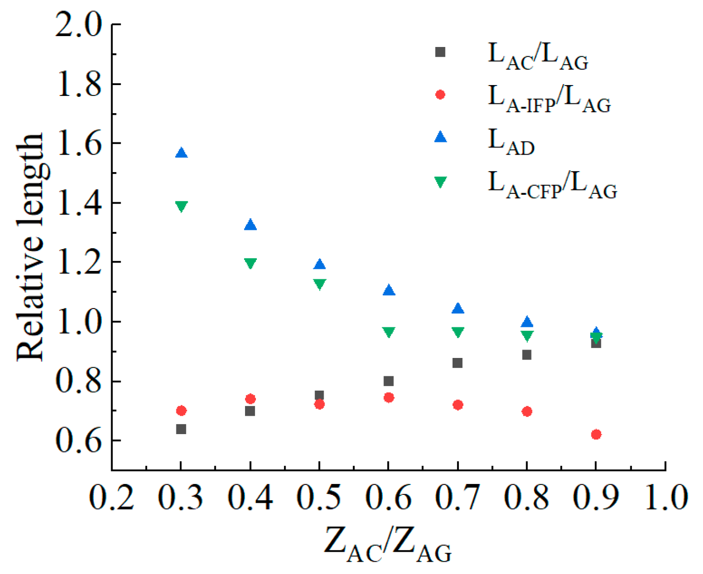
5.2. The Influence of the Jet Landing Point C Position on the Bottom Plate Shape Parameters

List the parameters of each part of the bottom plate obtained above in Table 1, and plot the relationship between ZAC/ZAG and the relative length LBC/LAG, the relative length LCD/LAG, and the relative total length LAD/LAG, as shown in Figure 2. As the ZAC/ZAG value increases, the relative length LBC/LAG gradually increases, the relative length LCD/LAG significantly decreases, and the relative total length LAD/LAG gradually decreases. This indicates that the larger the ZAC/ZAG value, the closer point C is to point G, the steeper the slope of the jet landing point C, and the less likely the cavity is to backflow.

5.3. Numerical Simulation

To visually observe the shape of the cavity, turbulent numerical simulation was used to simulate and calculate these seven types of body shapes.

5.3.1. Computational Model

The numerical simulation calculation area includes the upstream reservoir, pressure tunnel section, gate chamber section, and non-pressure section, with a total length of about 1260 m, as shown in Figure 3. The RNG k-ε turbulence model is suitable for complex flows such as strongly turbulent water flow, jet collision, and separated flow. It considers the anisotropy of turbulence and corrects turbulence viscosity, which can repair complex turbulence simulations to a certain extent, and especially for situations with large flow amplitudes, the RNG k-ε model has more advantages, so this article adopts the anisotropic RNG k-ε turbulence model [25]. A coupled solution was obtained using the PISO algorithm, using unsteady flow to approximate constant flow for iterative calculation.
In order to accurately observe the shape of the cavity, the aerator section is the focus of simulation calculations. Due to its clear interface tracking, conservation, interface reconstruction techniques, wide applicability, and ease of implementation, the VOF method is particularly suitable for capturing air/water interfaces in simulations [26,27]. In this paper, the VOF [28,29,30] method is used to calculate the water/air interface. The basic principle of the VOF method is to define a fluid volume function F in each grid unit in the computational domain. When F = 1, it means that the grid unit is completely filled with a certain fluid phase. When F = 0, it indicates that there is no fluid phase in the grid cell. When 0 < F < 1, it indicates that the grid cell is filled with at least two fluid phases, and the cell is referred to as the interface between the fluids. The value of F can be obtained by solving Equation (11), which needs to satisfy the following transport equation:
F t + u F x + v F y = 0
In the formula, F is the ratio of the fluid volume within a certain unit to the total volume of that unit.

5.3.2. Grid Division and Boundary Conditions

Due to the fast convergence speed, high accuracy, and high computational efficiency of structured grids, the overall model of ecological drainage tunnels adopts structured grid division.
However, the grid size has a direct impact on the accuracy of capturing convective features. If the grid is too large, it may not be possible to capture the subtle structural changes at the lower edge of the jet water tongue behind the ridge; if the grid is too small, although it can improve accuracy, it will increase computation time and resource consumption. In order to reduce time and improve calculation speed, only the aeration facility section is encrypted. The grid size of this area along the X and Z directions is 0.1 m, and the grid size in the Y direction is 0.1 m, in order to obtain a clearer cavity shape. The connecting calculation areas are set as gradient grids, and the total number of grids is kept below 1.2 million; Figure 4 shows the local grid division of the aerator section. In the case of a known flow rate, the inlet boundary condition of the upstream reservoir area adopts a pressure inlet boundary, setting a characteristic water level for the verification flood level, corresponding to a flow rate of 983 m3/s. The outlet adopts a pressure outlet, and the ventilation port and the top surface of the reservoir are in contact with the atmosphere. The pressure inlet is given at standard atmospheric pressure, and the wall surface adopts a no-slip boundary condition. The viscous bottom layer is treated using the wall function method. The constant discrimination condition for numerical simulation calculation is that the error between the inlet flow rate and the outlet flow rate does not exceed ±5%.

5.3.3. Numerical Simulation Calculation Results

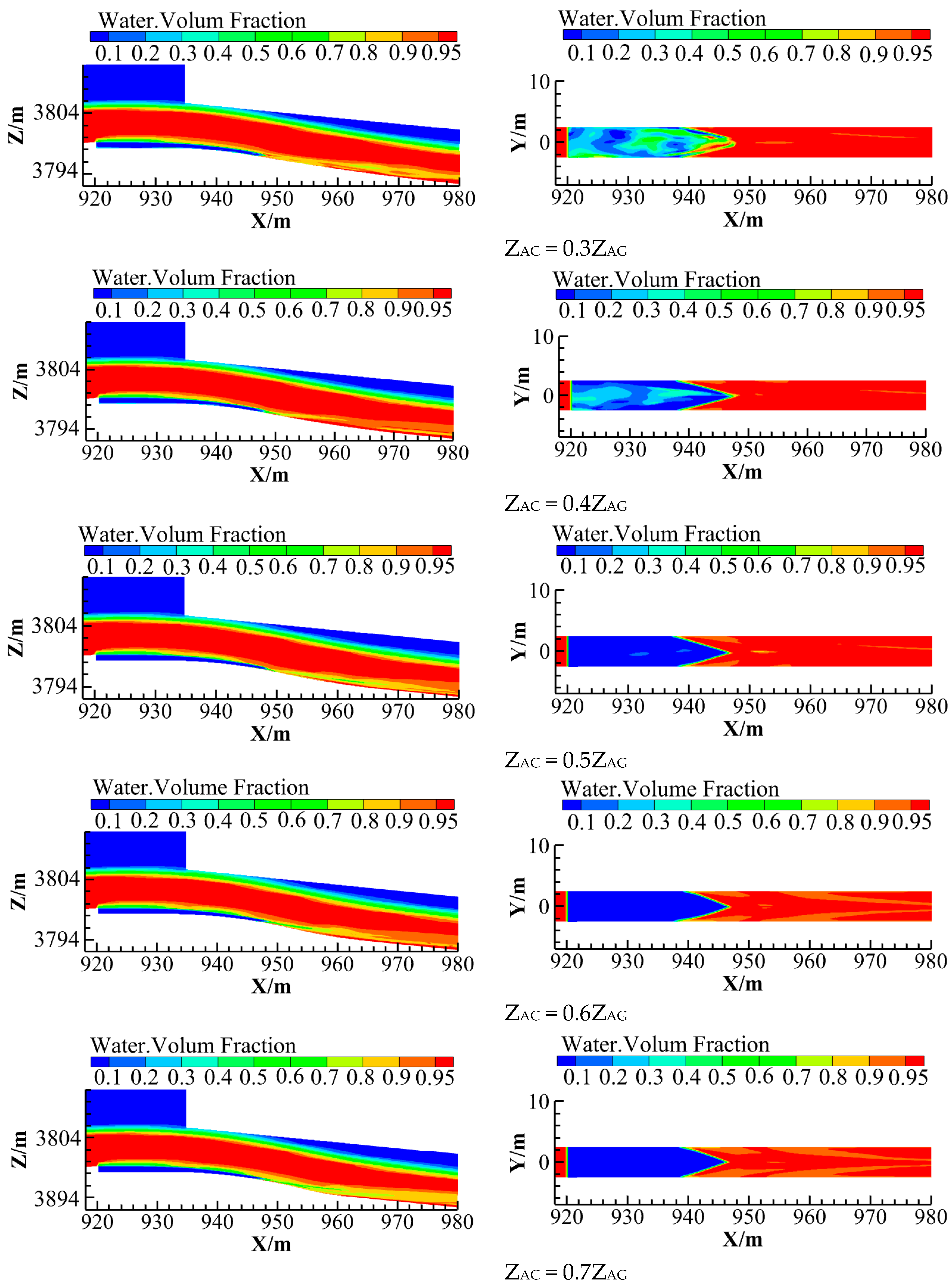
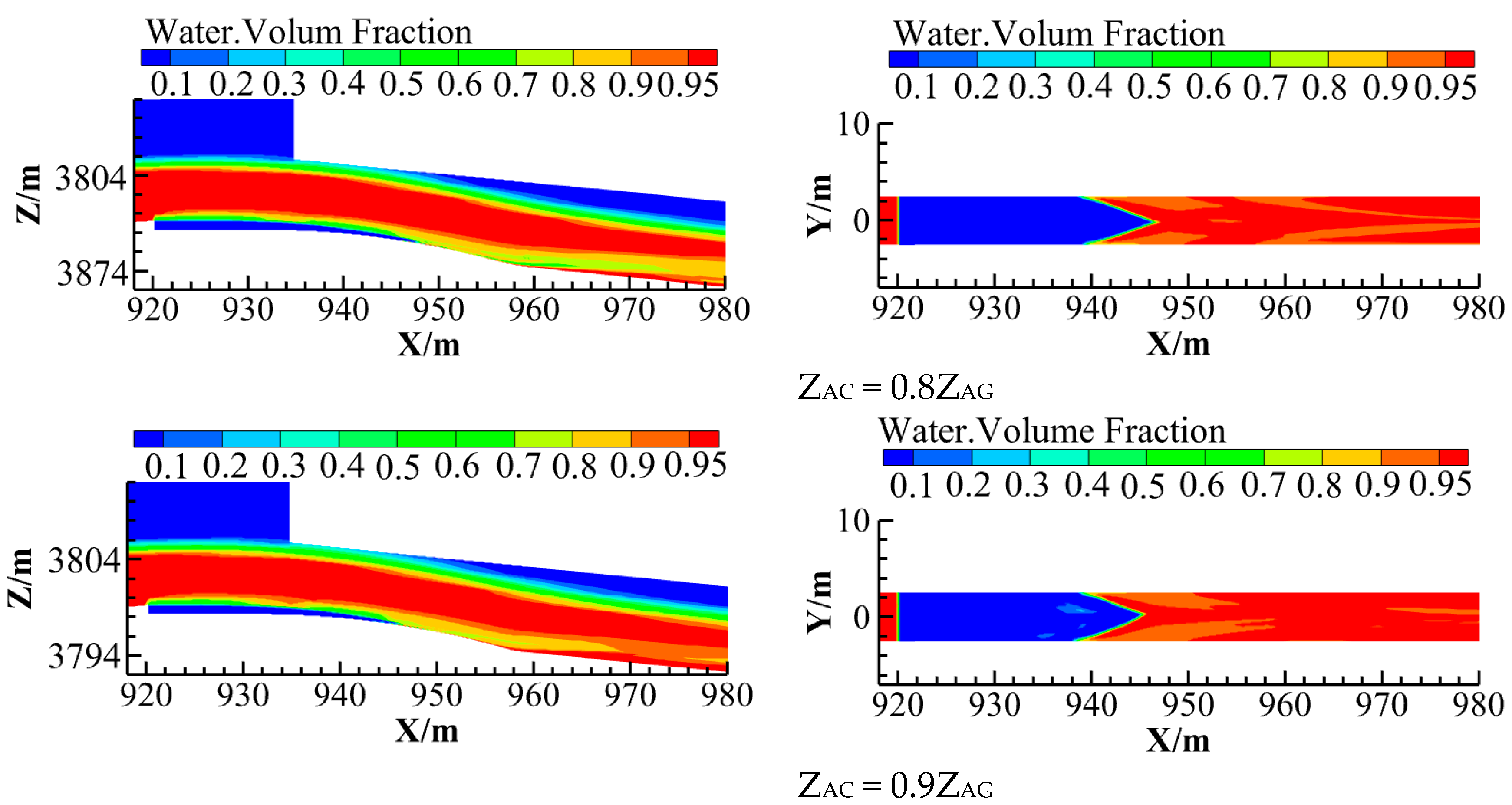
Calculate Cavity Shape

The numerical simulation first calculates “the small deflector + the offset“ combination aerator, and the calculated cavity shape is shown in Figure 5. Then, seven reasonable shapes designed in Section 4.1 and Section 4.2 are simulated and calculated. The calculated cavity shape of the longitudinal profile of the discharge channel bottom plate and the bottom plate are shown in Figure 6. (1) Due to the dual effects of small bottom slope and gravity, traditional aerators have severe cavity backflow and poor flow state. The seven reasonable types of aerators calculated using the design method in this article have stable cavities and better flow state than traditional aerating facilities. When ZAC/ZAG ≤ 0.5, there is a small amount of water accumulation in the cavity, and when ZAC/ZAG ≥ 0.5, there is almost no water accumulation in the cavity. (2) As the ZAC/ZAG value increases, the maximum net cavity length shows a trend of first increasing and then gradually decreasing. (3) The maximum net cavity length on the bottom plate of the discharge channel shows a shape of “convexity on the middle and concavity on both sides”, which is mainly due to the fact that in the two-dimensional continuous aeration facility the middle jet flow has a high velocity, while the jet flow on both sides has a low velocity.

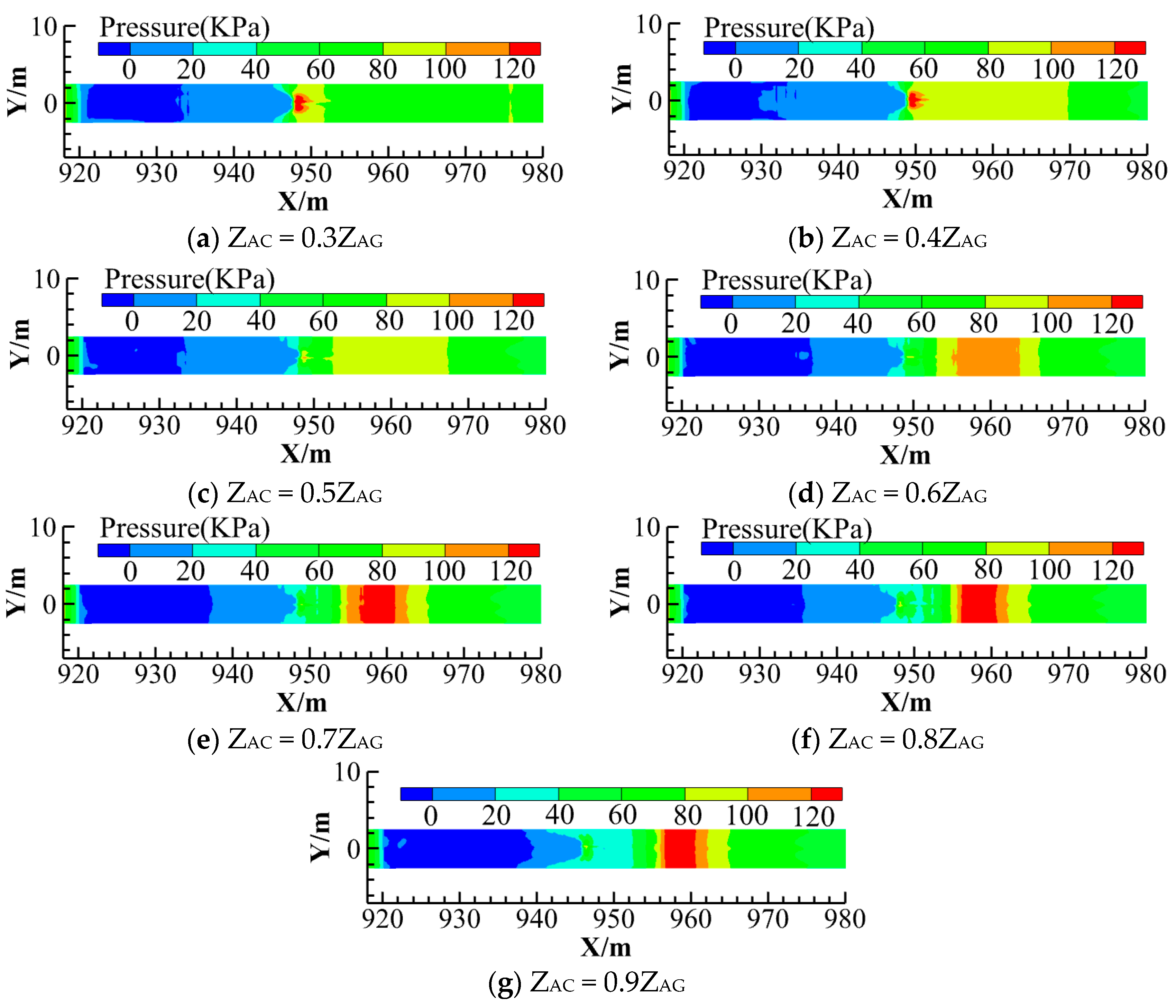
Distribution Characteristics of Bottom Plate Pressure

Time-average pressure distribution of the local bottom plates is shown in Figure 7 and the calculated value of time-average pressure at the centerline of the bottom plate is shown in Figure 8. Under different ZAC/ZAG values, we plot the relationship between relative convex parabolic segment LAC/LAG and relative impact force peak position LA-IFP/LAG, and the relationship between relative total length LAD/LAG and relative centrifugal force peak position LA-CFP/LAG is shown in Figure 9. (1) The pressure change in the platform bottom plate is not significant, with a range of −2 KPa < p < 0 KPa. When ZAC/ZAG = 0.6, the negative pressure is minimum, and when ZAC/ZAG = 0.9, the negative pressure is maximum. (2) The pressure distribution in the convex concave parabolic section shows a “bimodal” pattern. The maximum pressure value generated when the jet flow impacts the convex parabolic bottom plate is the impact force peak, and the maximum pressure value generated when the centrifugal force acts on the concave parabolic bottom plate is the centrifugal force peak. At the same ZAC/ZAG value, the pressure significantly increases to the impact force peak, gradually decreases and fluctuates within a certain range, then gradually increases to the centrifugal force peak and significantly decreases and tends to stabilize. (3) As the ZAC/ZAG value increases, the impact force peak first increases and then decreases, and the maximum net cavity length also increases first and then decreases, while the centrifugal force peak gradually decreases. Possible causes of this phenomenon are as follows: One reason is that as the ZAC/ZAG value increases, the concave parabolic section gradually decreases and rapid stream, resulting in the flow unable to discharge smoothly, causing the upstream jet flow to impact the bottom plate in advance, and the impact force peak and the centrifugal force peak to gradually coincide. Secondly, although the take-off angle of the lower jet trajectory is accurately calculated in the process of body shape design, the Froude number Fr calculation uses the average velocity in front of the aerator, resulting in a difference between the designed point C and the impact force peak position. Overall, the position of the impact force peak fluctuates back and forth within a certain range of the point C.
But regardless of the reason, when ZAC/ZAG ≥ 0.5, the calculated net cavity can still maintain a certain length and almost no water accumulation after the aerator.

6. Discussion

Through the above research, it has been found that under small bottom slopes and low Froude number engineering conditions, the “aerator + local steep slope” aerated facility can effectively suppress or reduce cavity backflow, and obtain a relatively stable aerated cavity. However, whether it is a special-shaped aerator or a combination of “aerator + local steep slope” aerator, when the bottom plate of the discharge channel decreases or the Froude number decreases, the accumulated water in the cavity cannot be eliminated due to the dual effects of gravity and small bottom slope, indicating a relatively weak adaptability. The double parabolic aerator is designed for engineering conditions such as small low slopes or flat bottom slopes. The basic principle of the design is to locally increase the bottom slope behind the offset, reduce the impact angle between the jet water tongue and the bottom plate, and keep the lower edge of the jet water tongue as close as possible to the local bottom plate. Locally increasing the bottom slope only changes the shape of the local bottom plate and does not change the size of the original bottom slope, which is independent of the size of the original bottom slope. It is suitable for a wider and stronger range of bottom slopes. In addition, both the irregular aerator and the “aerator + local steep slope” measures are determined through repeated engineering tests, which is time-consuming and laborious. The reason for this is that there is no design method with body shape parameters for reference, and it all depends on engineering experience. The double parabolic aerated facility has its own design method for body shape parameters, which can be used as a preselection scheme for designing the optimal body shape parameters of the aerated facility, saving time and effort.

7. Conclusions

To solve the problem of aeration and erosion reduction in discharge structures under conditions of small bottom slope, low Froude number, and large single-width flow rate, this paper proposes a new double parabolic aeration facility based on the concept of local steepening. The convex parabolic section is tangent to the flat section behind the ridge, and the concave parabolic section is tangent to the downstream bottom plate. The water tongue landing point is controlled at the junction of the convex concave parabolic curve, and the lower edge of the water tongue is in contact with the parabolic bottom plate. The calculation formula for the parabolic bottom plate has been theoretically derived, and a design method for the shape parameters of the aeration facility has been provided. Through engineering examples, it has been found that the larger the ZAC/ZAG value, the closer the C point is to the G point, and the less likely the cavity behind the offset is to retain water. When the water tongue landing point is 0.5–0.8 times the height of the water tongue impact point, there is almost no water accumulation in the calculated cavity. Therefore, the larger the ZAC/ZAG value, the better, under the condition of meeting the downstream connection conditions of the project. The research results of this article make up for the lack of experience in the design of aerated structures, and promote the quantification of aerated corrosion reduction in discharge structures, which has important engineering value. In addition, to increase the volume of the aerated cavity, systematic large-scale model experiments will be carried out in subsequent work to optimize the structural parameters of the double parabolic aerated facility and provide a design method for the optimal aerated facility body parameters.

Author Contributions

Conceptualization, G.L. and Y.D.; methodology, G.L. and Y.D.; validation, G.L. and Y.D.; formal analysis, Y.D.; investigation, Y.D.; resources, S.L. (Shaobin Liu); data curation, Y.D.; writing—original draft preparation, Y.D.; writing—review and editing, Y.D.; visualization, S.L. (Shanshan Li); supervision, P.L.; project administration, Y.W.; funding acquisition, G.L. All authors have read and agreed to the published version of the manuscript.

Funding

This study was funded by National Natural Science Foundation of China (Grant No. 52079107), National Natural Science Foundation Youth Program (Grant No. 52309105).

Data Availability Statement

The original contributions presented in the study are included in the article, further inquiries can be directed to the corresponding author.

Conflicts of Interest

Author Guodong Li was employed by State Key Laboratory of Eco-Hydraulics in Northwest Arid Region, Xi’an University of Technology. The remaining authors declare that the research was conducted in the absence of any commercial or financial relationships that could be construed as a potential conflict of interest.

References

  1. Xu, W.L.; Zhang, Y.L.; Luo, J.; Arong Zhang, Q. The impact of particles on the collapse characteristics of cavitation bubbles. Ocean. Eng. 2017, 131, 15–24. [Google Scholar] [CrossRef]
  2. Zhang, H.; Hu, H. Simulation of cavitation collapse process based on lattice Boltzmann method. J. Huazhong Univ. Sci. Tech. 2024, 52, 42–48. (In Chinese) [Google Scholar]
  3. Zhang, J.M. Hydraulics of high-speed flows: Recent achievements and future Outlook. J. Hydroelectr. Eng. 2021, 40, 1–16. (In Chinese) [Google Scholar]
  4. Bai, R.; Zhang, F.; Liu, S.; Wang, W. Air concentration and bubble characteristics downstream of a chute aerator. Int. J. Multiph. Flow 2016, 87, 156–166. [Google Scholar] [CrossRef]
  5. Shi, Q. High-Velocity Aerated Flow; China Water Resources and Hydropower Press: Beijing, China, 2007. [Google Scholar]
  6. Wei, W.R.; Deng, J. Wedge Aerator at the Bottom Outlet in Flat Tunnels. J. Hydraul. Eng. 2023, 149, 04022037. [Google Scholar] [CrossRef]
  7. Pfister, M.; Hager, W.H. Chute aerators. I: Air transport characteristics. Hydraul. Eng. 2010, 136, 352–359. [Google Scholar] [CrossRef]
  8. Pfister, M.; Hager, W.H. Chute aerators. II: Hydraulic design. Hydraul. Eng. 2010, 136, 360–367. [Google Scholar] [CrossRef]
  9. Zang, L.H.; Xu, W.L. Experimental investigation on the backwater behind aeration facility. J. Sci. Technol. Eng. 2006, 6, 2387–2389. (In Chinese) [Google Scholar]
  10. Pan, C.J.; Yuan, Y.Z. The study on the layout of aerators in free-flow spillway tunnel with inlet raised and the mild slope. J. Hydraul. Eng. 1993, 6, 61–66. (In Chinese) [Google Scholar]
  11. Sun, S.K.; Liu, H.T.; Wang, X.S. Optimistic study on the layout of aeration facilities under mild gradient. J. Water Resour. Hydropower Eng. 2004, 35, 26–29. (In Chinese) [Google Scholar]
  12. Wang, H.Y.; Dang, G.Q.; Yang, Q. Experimental study on V-type aerator for spillway tunnel with inlet raised. J. Hydraul. Eng. 2005, 36, 1371–1374. (In Chinese) [Google Scholar]
  13. Gao, A.; Wu, S.; Wang, F. Research progress of aeration cavitation reduction technology and aeration devices. Adv. Sci. Technol. Water Resour. 2019, 39, 86–94. (In Chinese) [Google Scholar]
  14. Sun, Z.; Wang, F.; Sun, C.; Feng, Y.; Fan, G.; Wu, S. Experimental analysis of hydraulic characteristics of aerators in spillway tunnels with mild slope. J. Hydroelectr. Eng. 2023, 42, 57–66. (In Chinese) [Google Scholar]
  15. Liu, S.B. Study on the Configuration of Aeration Facility on Small Bottom Slope. Master’s Thesis, Xi’an University of Technology, Xi’an, China, 2013. (In Chinese). [Google Scholar]
  16. Wang, H.Y.; Dai, G.Q.; Liu, C.; Yang, Q. Discussion of aerator bottom cavity backflow of discharge structures. Chin. J. Hydro Dyn. 2009, 24, 425–431. (In Chinese) [Google Scholar]
  17. Pfister, M.; Hager, W.H. Deflector-generated jets. J. Hydraul. Res. 2009, 47, 466–475. [Google Scholar] [CrossRef]
  18. Yang, Y.S.; Yang, Y.Q.; Shuang, Q.H. The hydraulic and aeration characteristics of low froude number over a step aerator. J. Hydraul. Eng. 2000, 2, 27–31. (In Chinese) [Google Scholar]
  19. Chanson, H. Predicting the filling of ventilated cavities behind spillway aerators. J. Hydraul. Res. 1995, 33, 361–372. [Google Scholar] [CrossRef]
  20. Steiner, R.; Heller, V.; Hager, W.H.; Minor, H.-E. De-flector ski jump hydraulics. J. Hydraul. Eng. ASCE 2008, 134, 562–571. [Google Scholar] [CrossRef]
  21. Rutschmann, P.; Hager, W.H. Air entrainment by spillway aerators. J. Hydraul. Eng. 1990, 116, 765–782. [Google Scholar] [CrossRef]
  22. Wu, J.H.; Ruan, S.P. Cavity length below chute aerators. J. Sci. China Technol. Sci. 2008, 51, 170–178. (In Chinese) [Google Scholar] [CrossRef]
  23. Pfister, M. Jet impact angel on chute downstream of aerator. In Proceedings of the 4th IAHR International Symposium on Hydraulic Structures, Porto, Portugal, 12–13 January 2012. [Google Scholar]
  24. Long, L.C.; Liu, C.; Deng, J.; Wei, W.R.; Ran, Y.B. Study on takeoff angle characteristics of continuous flip bucket’s ski-jump nappe. J. China Inst. Water Resour. Hydropower Res. 2023, 21, 83–91. (In Chinese) [Google Scholar]
  25. Deng, J.; Xu, W.L.; Lei, J.; Diao, M.J. Numerical simulation of hydraulic characteristics of high spillway tunnel. J. Hydraul. Eng. 2005, 36, 1209–1218. (In Chinese) [Google Scholar]
  26. Luo, Y.Q.; Diao, M.J.; He, D.M.; Bai, S.X. Three-dimensional numerical simulation analysis of air entrainment and erosion reduction of high dam open flow spillway tunnel. Adv. Water Sci. 2012, 23, 110–116. (In Chinese) [Google Scholar]
  27. Gao, X.P.; Jia, L.F.; Song, H.F.; Cui, G.H. Three-dimensional numerical simulation of aerated water flow behind the aerated sill of a spillway. J. Hydroelectr. Eng. 2014, 33, 90–96. (In Chinese) [Google Scholar]
  28. Xu, J.; Wu, J.; Yu, P.; Fei, M. Fin performance of 3D aerator devices with backward lateral deflectors. J. Hydrodyn. 2020, 32, 410–413. [Google Scholar] [CrossRef]
  29. Teng, P.; Yang, J. CFD Modeling of Two-phase Flow of a Spillway Chute Aerator of Large Width. J. Appl. Water Eng. Res. 2016, 4, 163–177. [Google Scholar] [CrossRef]
  30. Teng, P.; Yang, J.; Pfister, M. Studies of Two-phase Flow at a Chute Aerator with Experiments and CFD Modelling. Model. Simul. Eng. J. 2016, 2016, 4729128. [Google Scholar] [CrossRef]
Figure 1. Definition sketch with notation.
Water 16 01574 g001
Figure 2. Relationship between ZAC/ZAG and the relative lengths of each part of the bottom plate.
Water 16 01574 g002
Figure 3. Calculation Model.
Water 16 01574 g003
Figure 4. Local grid division of the aerator section.
Water 16 01574 g004
Figure 5. Calculated cavity shape of “the small deflector + the offset” combination aerator.
Water 16 01574 g005
Figure 6. Calculated cavity shape behind the offset.
Water 16 01574 g006aWater 16 01574 g006b
Figure 7. The time-average pressure distribution of local bottom plates under different ZAC/ZAG values.
Water 16 01574 g007
Figure 8. The time-average pressure distribution of local bottom plates centerline under different ZAC/ZAG values.
Water 16 01574 g008
Figure 9. The relationship between point C, point D, and bimodal relative position under different ZAC/ZAG values.
Water 16 01574 g009
Table 1. Type design based on this paper’s approach.
Design Shape Convex Parabolic Bottom PlatesConcave Parabolic Bottom Platesβ2
ZAC
/m
LAB/mLBC
/m
Calculation FormulasLCD
/m
Calculation FormulasZCD
/m
M0.31.20611.80613.861−0.00628x237.2920.000994x2 − 0.1741x5.1089.876
M0.41.60811.80616.305−0.00605x225.1400.001936x2 − 0.1972x3.73611.163
M0.52.01011.80618.461−0.00590x217.6010.003347x2 − 0.2177x2.79612.289
M0.62.41211.80620.416−0.00579x212.1630.005608x2 − 0.2363x2.04513.301
M0.72.81411.80622.214−0.00571x27.9090.009704x2 − 0.2534x1.39714.225
M0.83.21611.80623.887−0.00564x24.3940.019277x2 − 0.26926x0.81115.078
M0.93.61811.80625.460−0.00558x21.3800.066795x2 − 0.28420x0.26515.873
Disclaimer/Publisher’s Note: The statements, opinions and data contained in all publications are solely those of the individual author(s) and contributor(s) and not of MDPI and/or the editor(s). MDPI and/or the editor(s) disclaim responsibility for any injury to people or property resulting from any ideas, methods, instructions or products referred to in the content.

