Article

Designing the Spigot Structure of Hydrocyclones to Reduce Fine Particle Misplacement in Underflow

1
College of Mechanical & Electronic Engineering, Shandong University of Science and Technology, Qingdao 266590, China
2
Dandong Dongfang Measurement & Control Technology Co., Ltd., Dandong 118000, China
*
Author to whom correspondence should be addressed.
Water 2024, 16(7), 1070; https://doi.org/10.3390/w16071070
Submission received: 15 March 2024 / Revised: 26 March 2024 / Accepted: 27 March 2024 / Published: 8 April 2024
(This article belongs to the Topic Oil, Gas and Water Separation Research)

Abstract

:
Hydrocyclones can be used to concentrate the entrained sands in sewage and alleviate the clogging and erosion of the drainage network, but in practical application, there are problems such as low concentrations of underflow and a high content of fine particles, which cause a significant load on the subsequent sand dewatering and recycling. This paper designs five spigot structures of hydrocyclones and investigates the separation performance by numerical simulation, aiming to improve the applicability of hydrocyclones in the sewage treatment process by optimizing the spigot structure. The research results show that a large cone spigot delays the external downward swirling flow and reduces fine particle content in the underflow, but its effective separation space is reduced, and the turbulence in the cone section area is more intensive, which influences the separation accuracy. An elongated spigot has a reduced underflow water distribution; fine particles are more enriched in the internal swirling flow, and the underflow recoveries of 1 μm and 5 μm particles drop by 2.34% and 2.31%. The spigot structure affects the downward fluid and air intake states; complicated spigot structures contribute to increasing the resistance of particle discharge through underflow, alleviating fine particle misplacement.

1. Introduction

Hydrocyclones are used as centrifugal separation equipment in petrochemical, mineral separation, sewage treatment, biological, and other applications due to their easy operation, lack of moving parts, and small footprint [1,2,3,4]. Within a hydrocyclone is a nonhomogeneous mixture of centrifugal force, gravity, drag, and other multiple coupled forces under the effect of turbulence; additionally, the internal hydrodynamic properties and particle behavior are highly complex, and it is always difficult to obtain a satisfactory separation effect [5,6,7]. For the sewage treatment process, hydrocyclones can effectively remove the entrained sand in sewage and alleviate the clogging and erosion of the drainage network, but there are problems such as low underflow concentrations with plenty of fine particles in practical application, which affect the subsequent efficiency of sand dewatering and recycling. How to reduce the above issues while ensuring separation efficiency is a difficult and critical problem that limits hydrocyclone applications [8,9].
To alleviate fine particle misplacement in underflow and improve hydrocyclone separation efficiency, scholars have conducted much research on structures and operating parameters [10,11,12]. Cui et al. [13] reported that a proper increase in feed flux could contribute to the stabilization of flow fields, reduce particle misalignment in export products, and increase the adaptability to fluctuations in feed size. Pérez et al. [14] researched that the discharge angle of a hydrocyclone was an effective indicator to monitor the separation process, coarse feeding, and high-flow velocity conditions triggered the phenomenon of rope discharge in underflow, which reduced the separation accuracy and was accompanied by low-frequency vibration. Dubey et al. [15] combined high-speed photography and numerical simulation to quantify the relationship between the discharge angle and each structural parameter. Su et al. [16] reported that the design of a thick-walled, small-diameter vortex finder promoted the suppression of short-circuit flow, reduced coarse particle enrichment within overflow, and minimized the separation cut size. Ji et al. [17] reported that a spiral feed design reduced separation energy consumption, achieving guidance and pre-classification of feed particles and improving fine particle separation performance. A compound curve cone could prolong the residence time of particles, and Jiang et al. [18] conducted a desludging test on tungsten ore, which effectively improved concentrate recovery by 3.88%. Dou et al. [19] designed a flushing water hydrocyclone for coal separation, and a PSO-SVM model established through experiments could effectively predict the separation parameters most suitable for coal slurry classification.
A spigot structure Is critical for reducing fine particle misplacement in underflow in hydrocyclones, and illustrating the behavior of fine particles in the separation field can also provide a design reference [20,21,22]. Zhang et al. [23] used numerical simulation to explore the relationship between spigot diameter and feed size, finding that appropriately enlarging the spigot reduces the disturbance of feed size fluctuation and decreases the mismatch particles in underflow. Yamamoto et al. [24] researched that the design of the inclined ring, apex cone, and center rod, structures below the spigot of the hydrocyclone, could effectively reduce the separation energy consumption and cut size. Tian et al. [25] designed a hydrocyclone with a flowback device, and simulations found that with increasing underflow back pressure, the resistance of particles discharged through the spigot increases and the underflow flow ratio decreases. Hou et al. [26,27] analyzed the feasibility of a flat-bottomed structure based on the theory of recirculating flow and researched the effects of the bottom contour and top opening size of hydrocyclone separation columns. Pathak et al. [28] conducted experiments and found that an expanding spigot structure could effectively alleviate the roped discharging phenomenon under the condition of coarse-grained and high-concentration feeding. Jiang et al. [29,30] evaluated the ability of a “W-shaped” spigot to reduce fine particle misplacement and improve the separation accuracy in detail; they successfully applied this to an iron mine, with fine particles less than 74 μm in the underflow decreasing by 1.46%. Han et al. [31] inserted an inner cone and cylinder at the bottom of a hydrocyclone cone and spigot and conducted tests, which showed that the structure of the inner cone and cylinder has no effect on particle separation efficiency but can significantly reduce the separation energy consumption.
The CFD method has been extensively applied to the optimization design of hydrocyclones to study internal flow fields and particle micromotion characteristics, with the advantages of accuracy, high efficiency, and short duration [32,33]. For the numerical simulation of hydrocyclones, multiphase models commonly utilize the VOF model, mixture model, and Eulerian model, while turbulence models include RSM and LES models; the DPM is used to track particle trajectories [34,35,36]. Durango-Cogollo et al. [37] reported that the RSM and LES models have higher computational accuracy than the k-ε model, but the RSM has faster computational efficiency and lower mesh quality requirements. Zhang et al. [38] coupled the VOF-RSM model to study the air core shapes and field characteristics of hydrocyclones, and their simulation results agreed well with PIV test data. Fang et al. [39] used a mixture model and an RSM model for a natural gas hydrate desanding simulation, which successfully predicted the influence patterns of sand size and the sand and natural gas hydrate inlet volume fractions on the recovery rate. Padhi et al. [40] introduced the ASM model by modifying the mixture model with shear lift, impeded settlement resistance, and a viscosity coefficient and predicted the classification performance for multicomponent simulations of silica and magnetite powders. Vakamalla et al. [41] modified the ASM model to simulate the separation process under high-concentration feeding conditions and reported that the high-concentration feeding caused the turbulence intensity to enhance, which caused the air core to decrease and fluctuate, reducing the separation accuracy of the hydrocyclone.
Therefore, to alleviate fine particle misplacement in underflow, this paper designs five new spigots, uses the CFD method to carry out simulation analysis, and explores the flow field and separation properties of hydrocyclones with different design structures to determine the most suitable spigot structure for the separation of fine particles. These findings will help to enrich the theory of fine particle separation, provide a reference for the structural optimization of hydrocyclone spigots, and provide design guidance for the popularization and application of hydrocyclones in the sewage treatment industry.

2. Numerical Methods

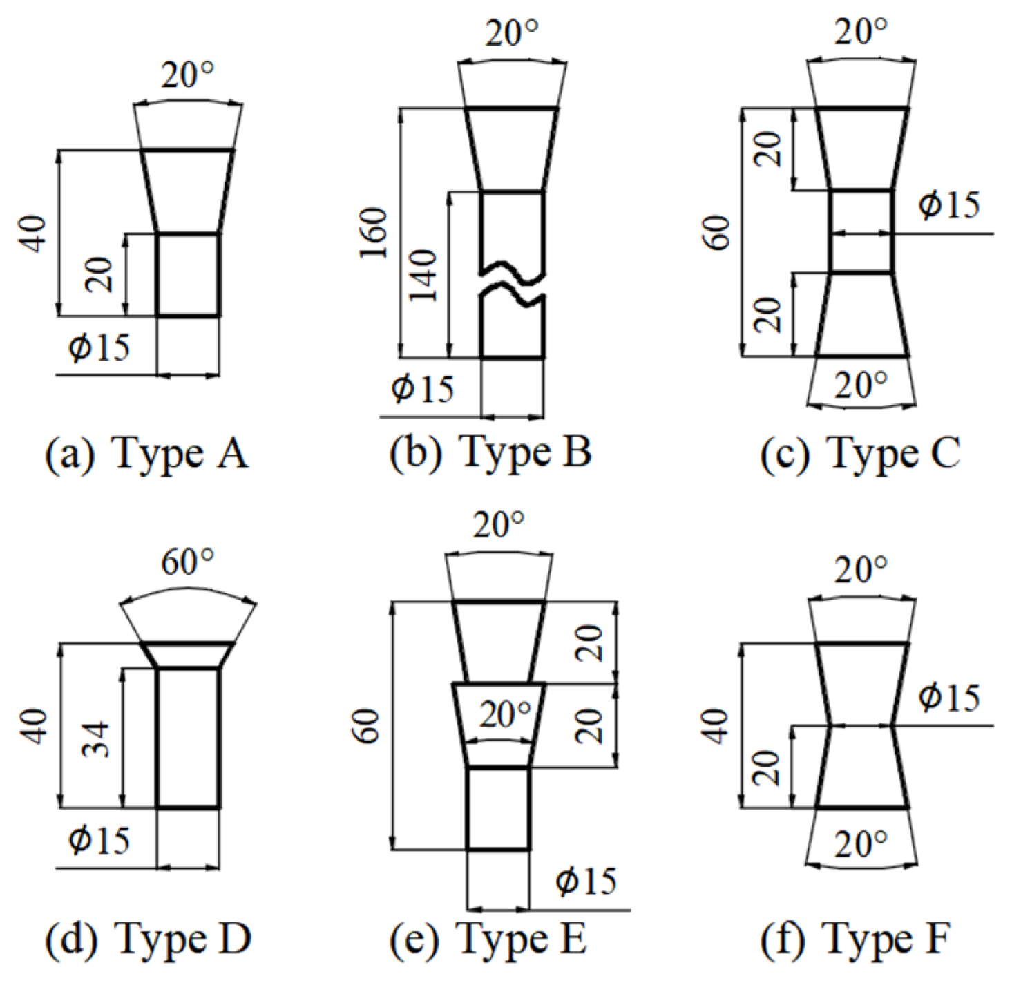
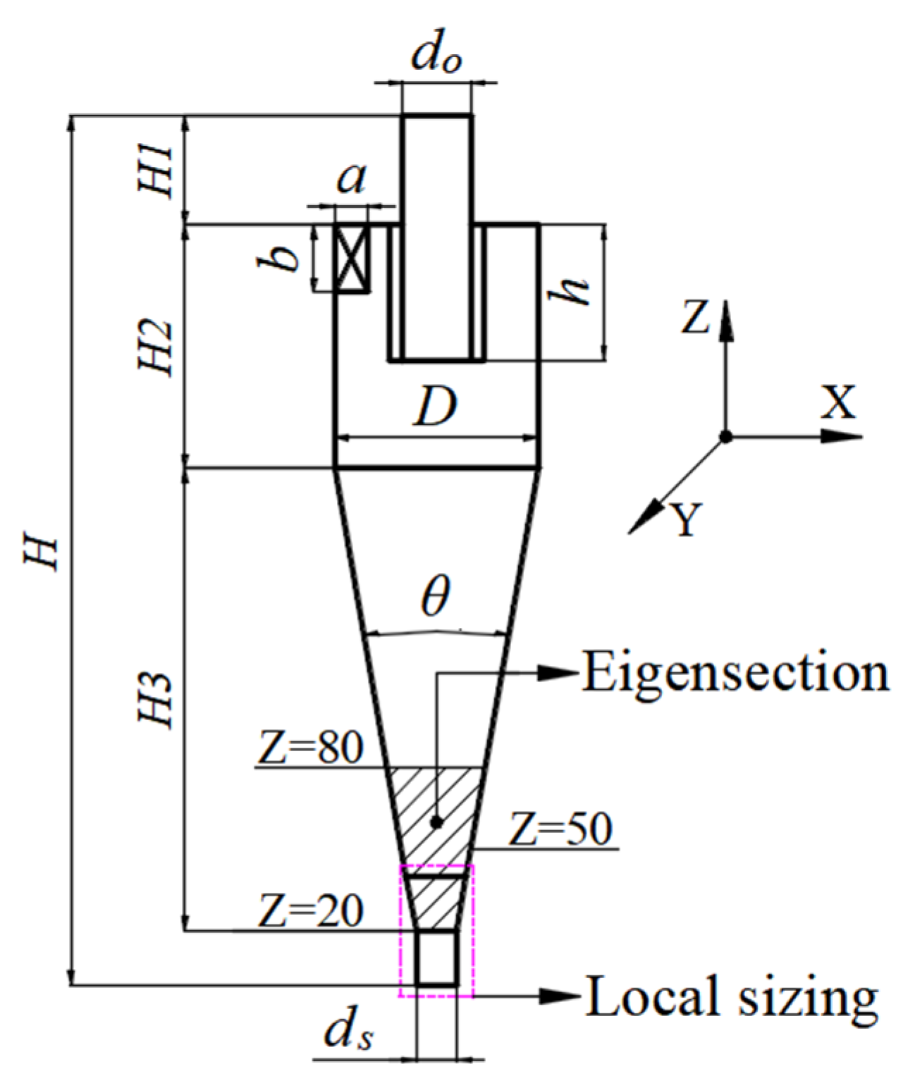
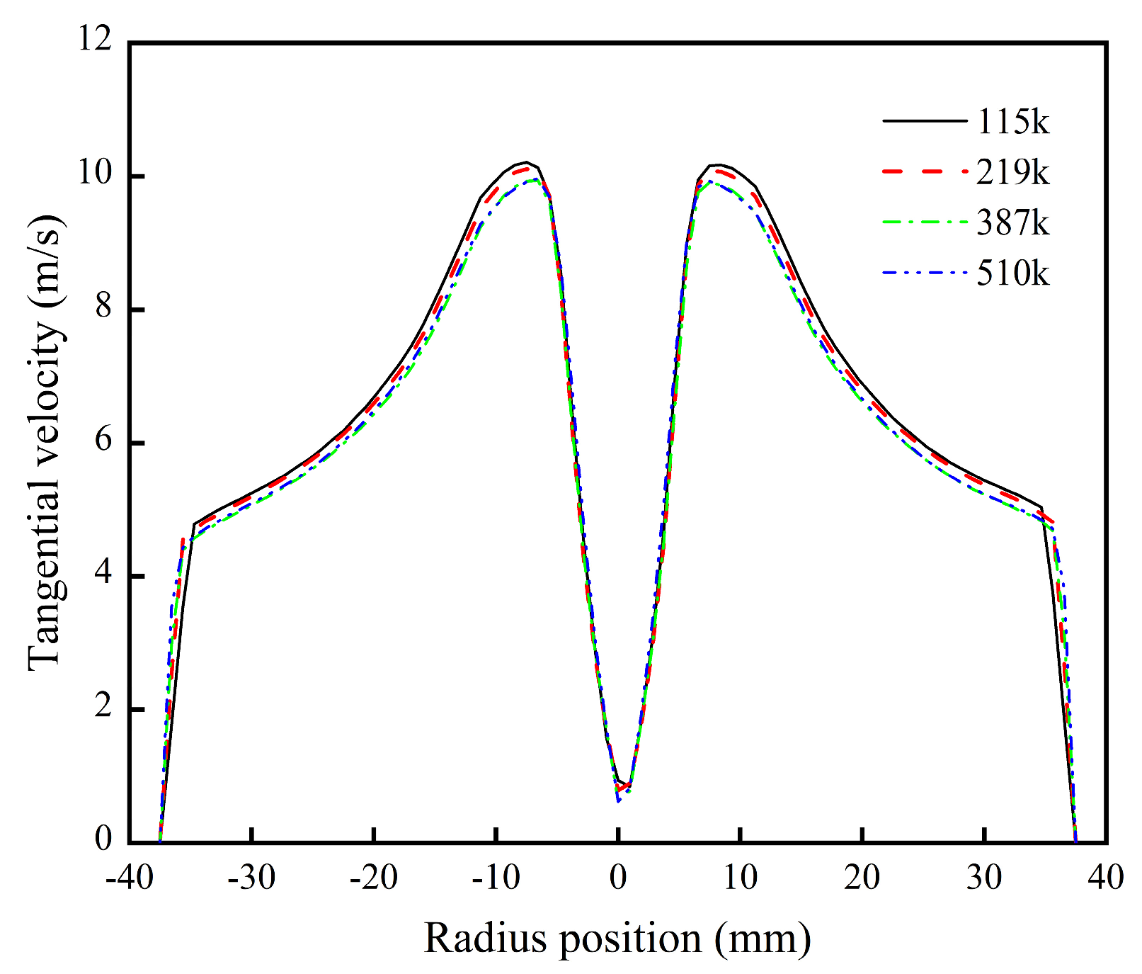
2.1. Geometry and Meshes

This paper takes a Φ75 mm regular hydrocyclone (Type A) as the structural basis; the structure is schematically shown in Figure 1, and the structural parameters are shown in Table 1. To further analyze the effects of the spigot structure, five new spigot structures, namely elongated (Type B), double-cone (Type C), large-cone (Type D), step-cone (Type E), and anti-cone (Type F) structures, are designed as shown in Figure 2.
This study conducts hexahedral structured meshing of the computational model and encrypted meshes adjacent to the model wall, vortex finder, and spigot; the mesh numbers are 115 k, 219 k, 387 k, and 510 k. To verify the independence of the grid number, the tangential velocity distribution of 20 mm in the height section above the cylinder–cone interface is used as an analytical target. As shown in Figure 3, the value of tangential velocity and distribution patterns no longer change when the grid number reaches 387 k; therefore, the model grid number of the follow-up computational field is controlled at 387 k. Under the standard wall function setting, the Y-Plus value is an important element for evaluating the reasonability of grids in the computational field. For hydrocyclone simulation, the Y-Plus value is usually 15~200 [42]. The verification of the Y-Plus value is shown in Figure 4, which indicates that the Y-Plus grid in the localized sidewall area of the vortex finder has a maximum value lower than 220, which means that the mentioned grids can meet the computational requirements of this paper.

2.2. Model Description

Within hydrocyclones, turbulent movement completely develops and is characterized by a significantly high flow velocity and strong swirling; thus, choosing a reasonable mathematical model and simulation strategy is crucial for ensuring accurate calculations. The simulation process was conducted in two steps in this study. First, a VOF-RSM model was used to calculate the air and water phase motions in the swirling field to determine the gas–liquid flow field distribution pattern within the hydrocyclone. Based on these steps, a mixture model was chosen to add discrete-phase particles to calculate the gas–liquid–solid flow field. The simulation method has been previously applied to the R&D of hydrocyclones [8,18,30,42].

2.2.1. Turbulence Model

The RSM turbulence model is suitable for complex 3D flows involving strong streamline curvatures and powerful swirling. Compared with LES, DES, and other models, which are more computationally efficient, the demand solution of the Reynolds stress transport equation is
t ρ u i u j ¯ + x k ρ u i u j ¯ = D T , i j + D L , i j + P i j + G i j + ϕ i j + ε i j + F i j
where DT,ij is the diffusion by turbulent kinetic energy:
D T , i j = x k ρ u i u j u k ¯ + p u i ¯ δ k j + p u j ¯ δ j k
DL,ij is the diffusion by molecular viscosity:
D L , i j = x k μ x k u i u j ¯
Pij is the shear stress production:
P i j = ρ u i u k ¯ u j x k + u i u k ¯ u i x k
Gij is the buoyancy production:
G i j = ρ β g i u j θ ¯ + g j u i θ ¯
Φij is the stress–strain:
ϕ i j = p u i x j + u j x i ¯
εij is the viscous dissipation:
ε i j = 2 μ u i u j ¯ x k x k
Fij is the production by system rotation:
F i j = 2 ρ Ω k u j u m ¯ e i k m + u i u j ¯ e i k m
where eijk is the alternating symbol: eijk = 1 when the three indicators i, j, and k are different with positive order, eijk = −1 when the three indicators are different with reverse order, and eijk = 0 when there are duplicates of the three indicators.

2.2.2. Multiphase Flow Model

The VOF model is suitable for solving two-phase or multiphase incompatible fluids; the sum of all phase volume fractions in the control volume is 1:
q = 1 n α q = 1
where n is the number of granular phases; αq is the volume fraction of the qth phase.
The mixture models are suitable for multiphase flow calculations because they involve constructing mixed interphase continuity and momentum equations to find solutions and describing the motion of discrete phases by their relative velocities; the continuity equation is
t ρ m + ρ m v m = 0
where ρm is the density of the mixture phase; vm is the average velocity of the mixture phase.
The momentum equation is
t ρ m v m + ρ m v m v m = p + μ m v m + v m T + ρ m g + F v + k = 1 n α k ρ k v k r v k r
where v k r is the relative slip velocity of phase k with the mixture phase, m/s; the formula is
v k r = v k q k = 1 n α k ρ k ρ m v k q

2.3. Simulation Conditions

The inlet was set as “Velocity Inlet”, the velocity of each phase was 5 m/s, and the mass concentration of the feed particle phase was approximately 10%, equivalently 4% by volume, with no air. The overflow and underflow were set as “Pressure Outlet” with an air return coefficient of 1, and the wall was selected as the standard wall surface with no slip. The transient solution method was employed with a time step of 1 × 10⁻⁴ s. A quartz sample of 2650 kg/m3 was selected for the particle phase. The sample was divided into 9-grain levels and replaced by the corresponding characteristic diameters; the compositions and distribution are shown in Table 2.

3. Results and Discussion

This study selected a height section of Z = 50 mm and an axial section (Z = 20~80 mm) near the underflow export as the characteristic section for subsequent data analysis.

3.1. Flow Pattern

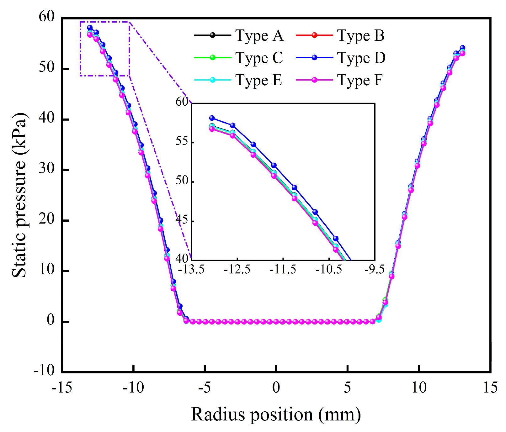
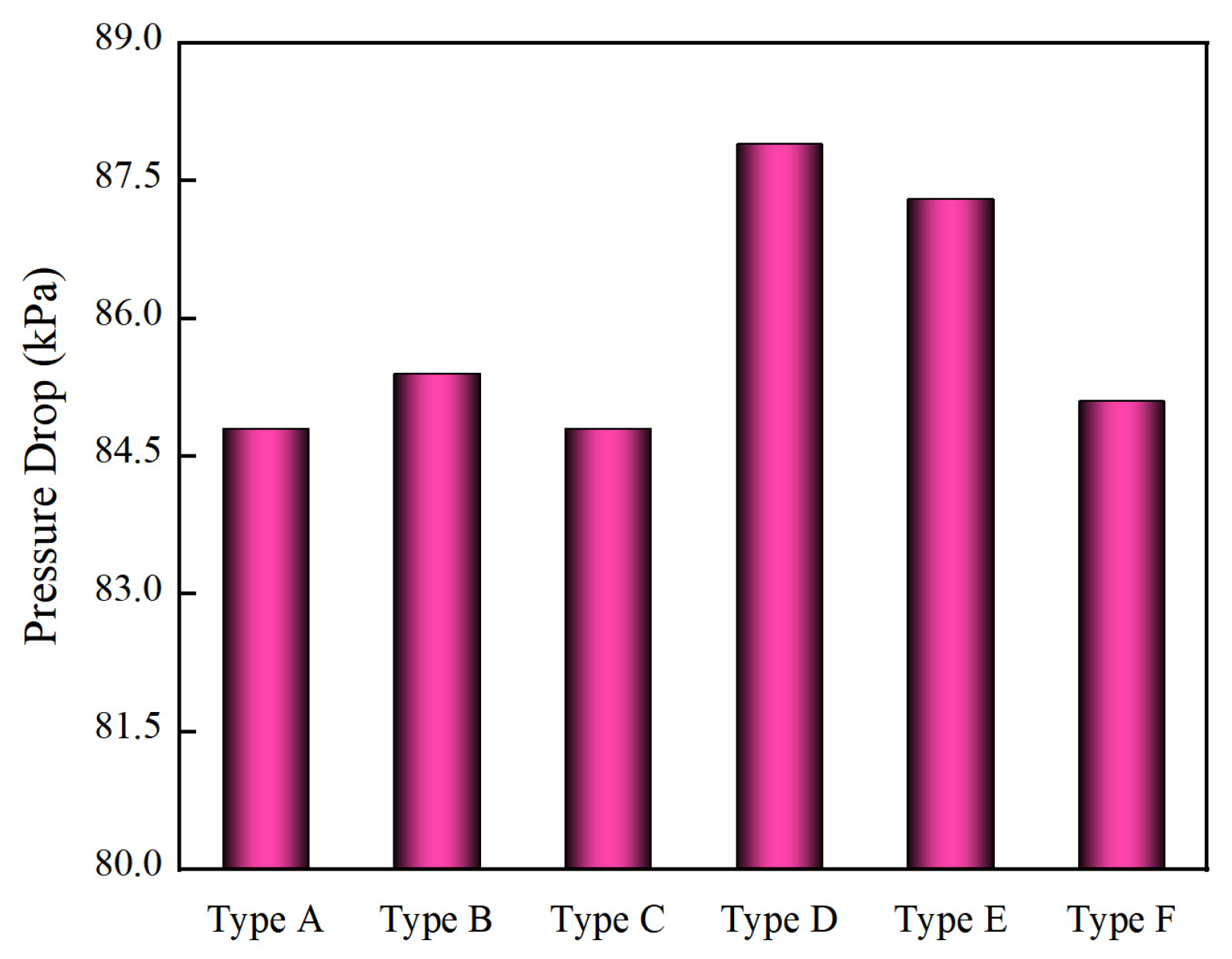
3.1.1. Static Pressure

The static pressure influences the capacity and separation cut size of the hydrocyclone, reflecting separation energy consumption. Figure 5 is the distribution curve of static pressure at a typical height, and shows that the change in the spigot structure does not affect the static pressure distribution pattern in the swirling field, which has little effect on static pressure; only the Type D hydrocyclone is slightly higher in equal radial position than other structures. The reason is that the large cone angle design of the Type D hydrocyclone hinders the external swirling flow downward, which forms a more significant pressure gradient at the inflection point of structure change and feeds back upward, making the fluid in the same radial position carry more energy to participate in the separation process, which contributes to strengthening the centrifugal field and reduces fine particle mismatch in the underflow.
The pressure drop is typically used to describe the energy loss during the separation process and refers to the pressure voltage of the inlet and overflow. As shown in Figure 6, compared with that of the regular Type A hydrocyclone, the pressure drops in Type D with a large cone and Type E with a step cone increase by 3.1 kPa and 2.5 kPa, respectively. The reason is that the incoherence of the bottom outlet structure weakens the guiding effect of the hydrocyclone wall on the fluid, expanding the probability of fluid collision, redirection, and other behaviors, improving the energy consumption of hydrocyclone separation.

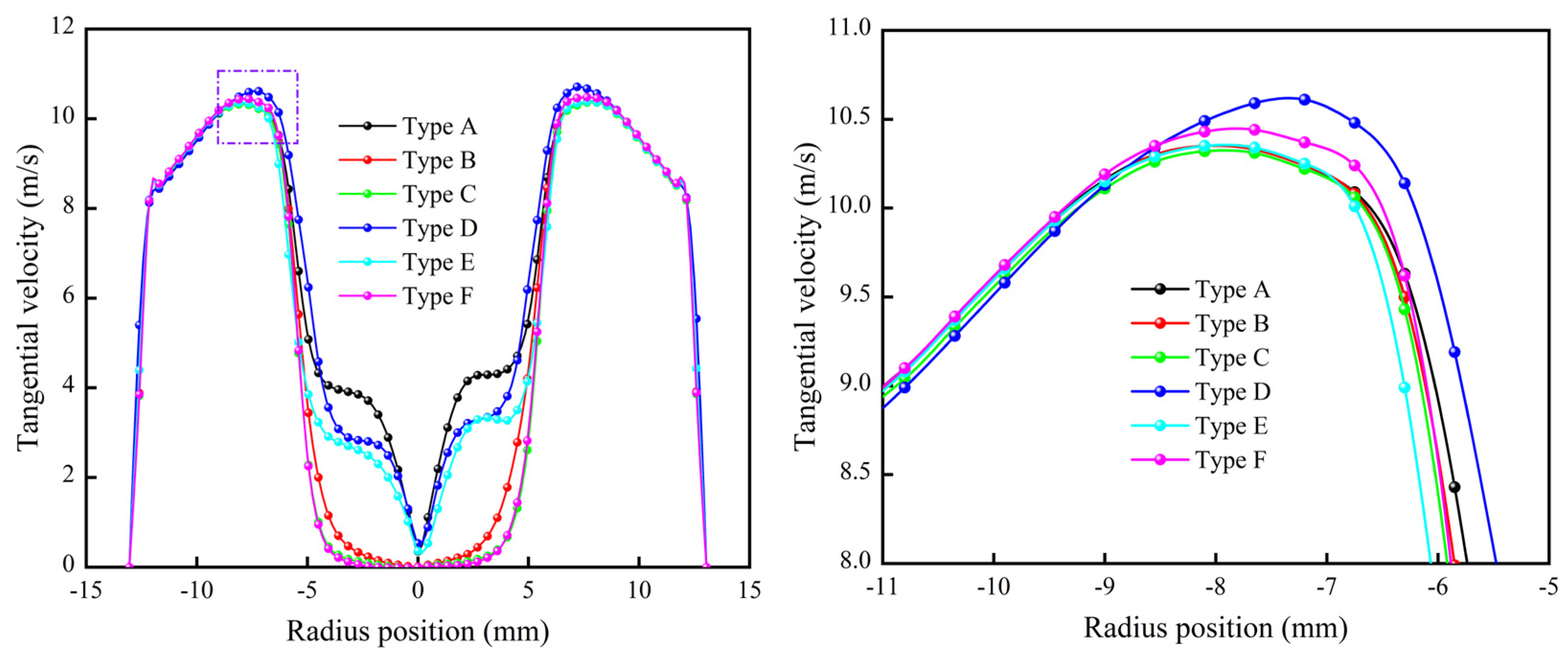
3.1.2. Tangential Velocity

Figure 7 shows the distribution curves of the tangential velocity at a typical height. The change in the spigot structure has a significant effect on the region of the forced eddy, but this portion is mostly occupied by the air core. The tangential velocity of Type D reaches a maximum of 10.61 m/s, followed by Type F, which is slightly larger than other structures. The increase in tangential velocity contributes to strengthening particle dislocation in the radial position, promoting mismatched particles entrapped in internal swirling flow to migrate outward. However, compared with the other types of hydrocyclones, the maximum tangential velocity trajectory of Type D is shifted outward by 1 mm and the effective separation space is reduced, which affects the separation accuracy to a certain extent.

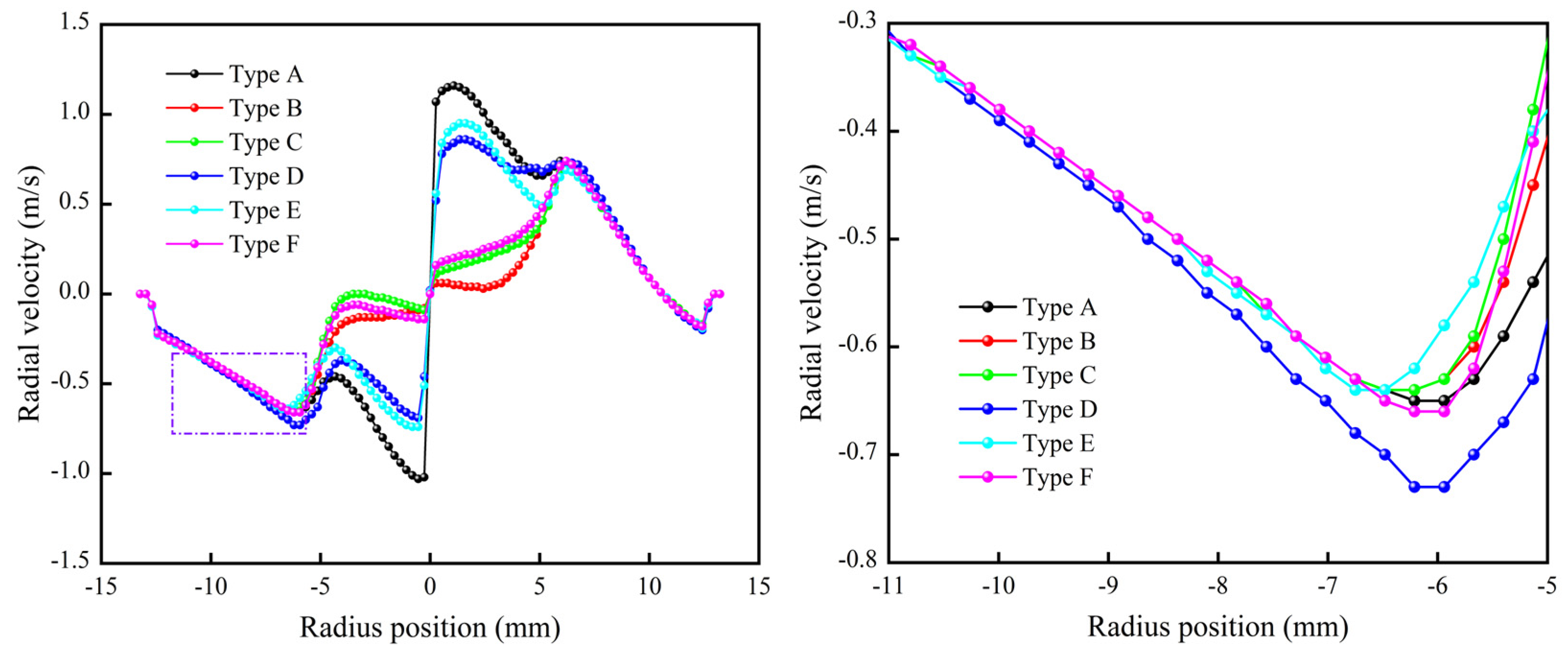
3.1.3. Radial Velocity

Figure 8 shows the distribution curves of radial velocity at a typical height. The absolute value of Type D is the largest in the semi-free eddy region of the main separation zone and is 12.3% greater than that of Type A, which promotes the inward migration of fine particles and increases the separation cut size. In the forced eddy region, Type B, Type C, and Type F have smaller radial and tangential velocities, and the increase in the function of radial velocity reduces the resistance of the outward migration of mismatched coarse particles within the forced eddy, reducing the number of overflow runs.

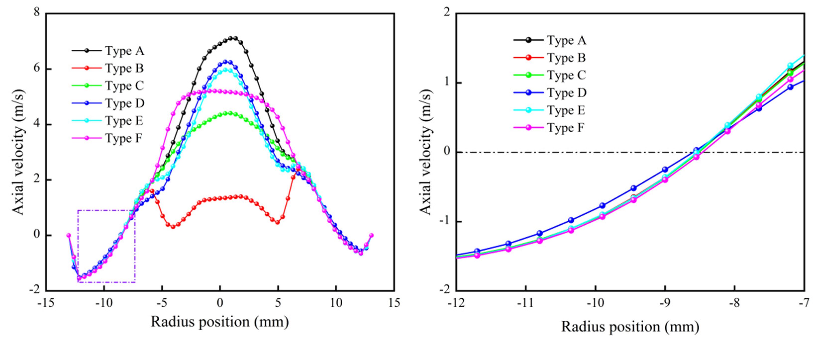
3.1.4. Axial Velocity

Figure 9 shows the distribution curves of axial velocities at a typical height. The spigot structure has a large impact on the axial velocity within a forced eddy, which is reflected mainly in the difference in the air intake velocity and less in the position of the LZVV. In the region of external swirling flow, the axial velocity of Type D is lower than that of Type B, the downward velocity is lower, the effect of the following particles is weaker, the process of fluid separation is more sufficient, and the elution effect of fine particles is more obvious, which contributes to a reduction in fine particles within the underflow. Compared with other structures, Type B has a significantly lower axial velocity in the internal swirling flow, which makes it easier for mismatched coarse particles to re-enter the separation process.

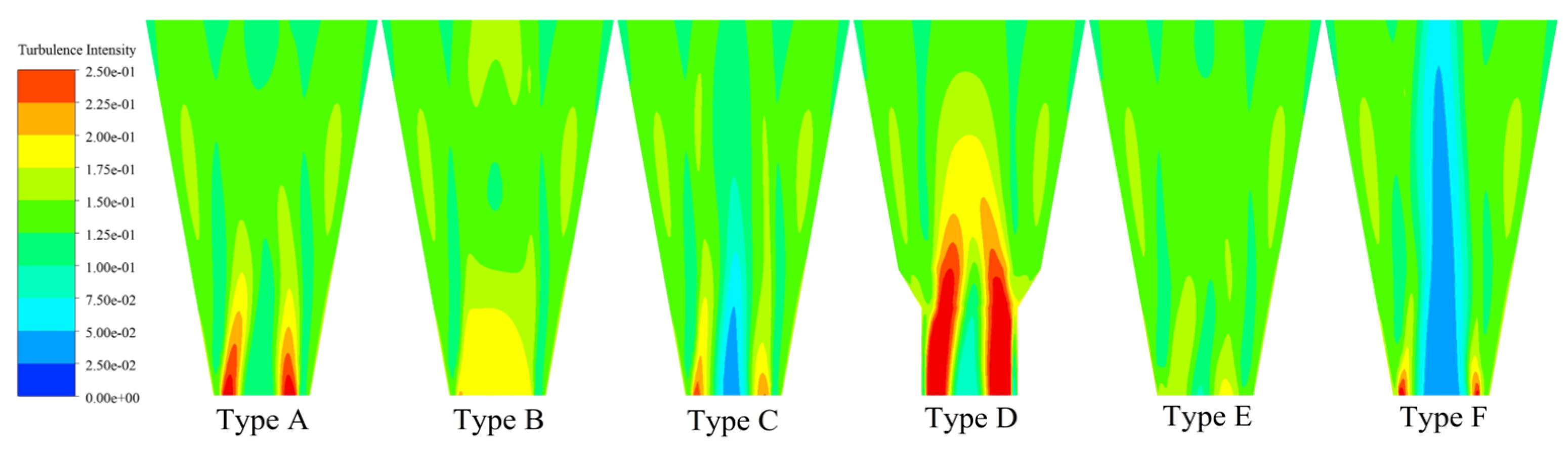
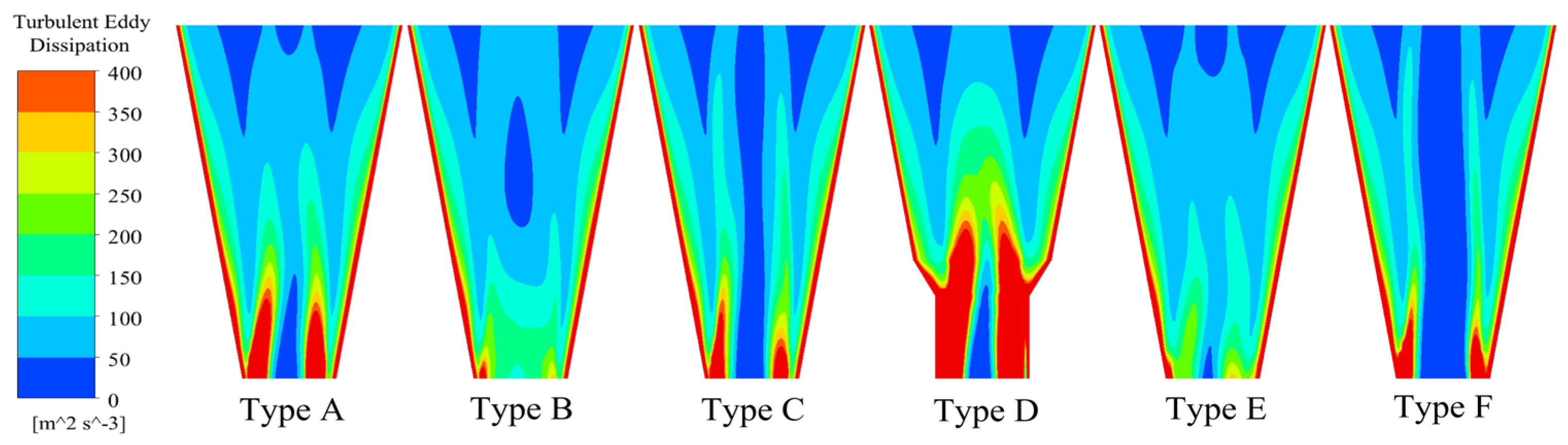
3.1.5. Turbulent Flow

The hydrocyclone separation field is a complicated and nonlinear turbulence field with multi-scale eddies, and the turbulence intensity and turbulent eddy dissipation can be used as indicators for evaluating turbulence development and attenuation. Figure 10 and Figure 11 show the distribution of turbulence intensity and turbulent eddy dissipation in the eigensection. As shown in the figures, the distribution patterns of the turbulence intensity and turbulent eddy dissipation are similar, and the spigot structure affects the air intake velocity, which has a significant influence on the turbulence intensity and turbulent eddy dissipation in the forced eddy region. The large-cone design of the Type D hydrocyclone increases the probability of fluid collision during the process of downward flow through an external swirling flow, which generates internal friction energy consumption; thus, the turbulence intensity and turbulent eddy dissipation increase. The elongated design of Type B and the step-cone of Type E slow the air intake velocity and reduce the gas-phase perturbation of the flow field in the eigensection, which helps to loosen the flow field to improve the fine particle separation accuracy.

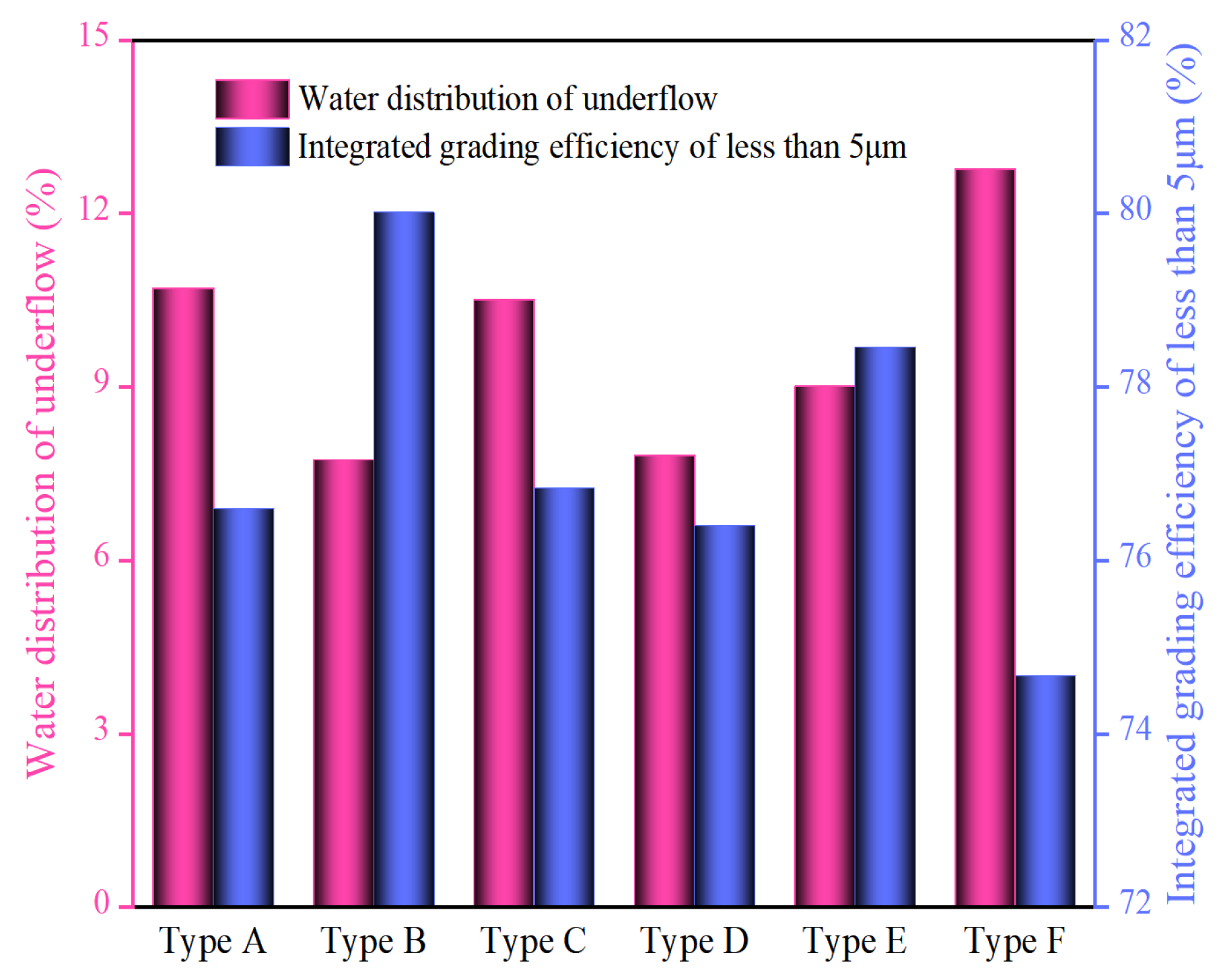
3.2. Separation Performance

3.2.1. Separation Efficiency

The hydrocyclone efficiency curve indicates the mass percentage of different particles of feed material in the underflow and the corresponding relationship between each particle size. The formula is
E a = θ ( β α ) α ( β θ ) × 100 %
where Ea is the hydrocyclone separation efficiency, %; α, β, and θ are the proportion of total particles of the featured particles in the feed, overflow, and underflow, respectively.
Efficiency curves visualize the separation performance of hydrocyclones and are an important index for evaluating separation processes. As shown in Figure 12, compared with those in the regular Type A, the problem of fine particle misplacement in underflow was more common in the anti-cone Type F hydrocyclone, and the elongated Type B, large-cone Type D, and step-cone Type E spigot structures were all capable of effectively alleviating the issues above. The reason is that for the fine particles entrained in the underflow, classified as mismatched particles, in the more complex spigot structure, the resistance and duration of fine particles discharged through the spigot increase, leading to a greater chance of re-entry to internal swirling flow, which is most obvious in the Type B structure. Similarly, the recoveries of the 1 μm and 5 μm particles decrease by 2.34% and 2.31%, respectively. For the Type D hydrocyclone, the downward resistance of the external swirling flow increases, resulting in additional internal swirling flow and more fine particles being caught in the overflow.
This study selects the cut size (d50), the possible deviation (Ep), and the imperfection (I) to quantitatively evaluate the efficiency curve. The d50 refers to the particle size corresponding to a recovery value of 50%; a larger gradient of d50 around the middle curve indicates a greater separation accuracy, which is evaluated by Ep and I. The Ep and I values are as small as possible, and their formulas are
E p = d 75 d 25 2
I = d 75 d 25 2 d 50
where d25 and d75 refer to the particle sizes for which the recovery values on the efficiency curves correspond to 25% and 75%, respectively.
Table 3 shows a comparison of the d50, Ep, and I of several structures. As shown in the table, the Ep and I values of the Type D hydrocyclone with a large cone increase by approximately 0.4 and 0.1, respectively, its cut size increases by approximately 1 μm, and the overflow and underflow product sizes become coarser. The large cone expands the turbulence intensity, and and energy consumption in the cone section separation area reduce the effective separation space and decreases the separation accuracy.
This study aimed to alleviate fine particle displacement in underflow by designing the spigot structure data to quantify the analysis data better; 5 μm fine particles and 15 μm particles, which are close to the cutoff size, were selected as the characteristic particle sizes for subsequent data analysis.

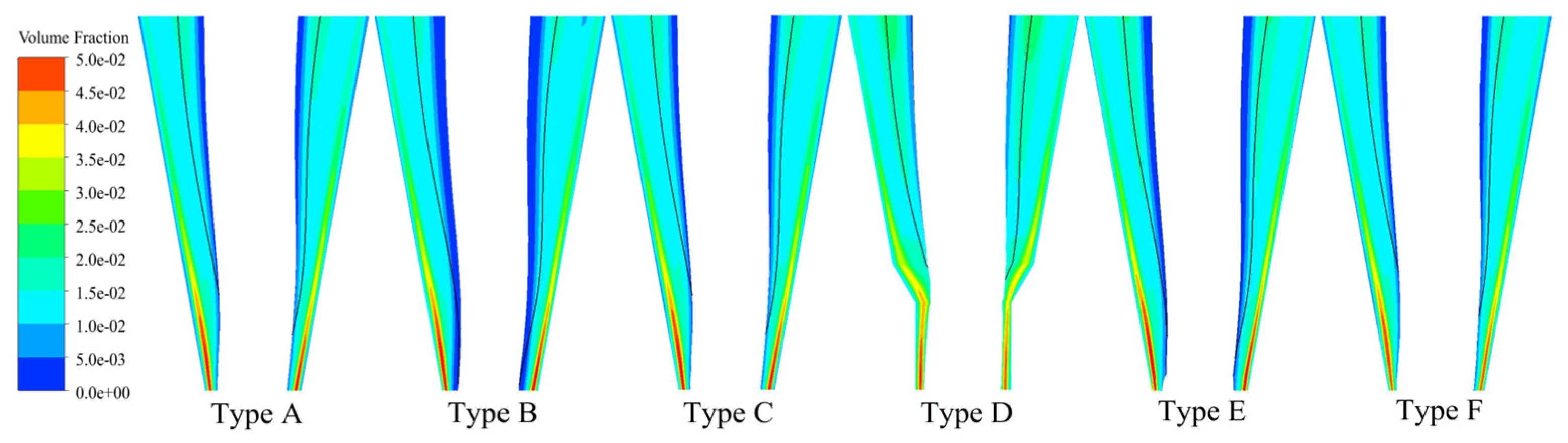
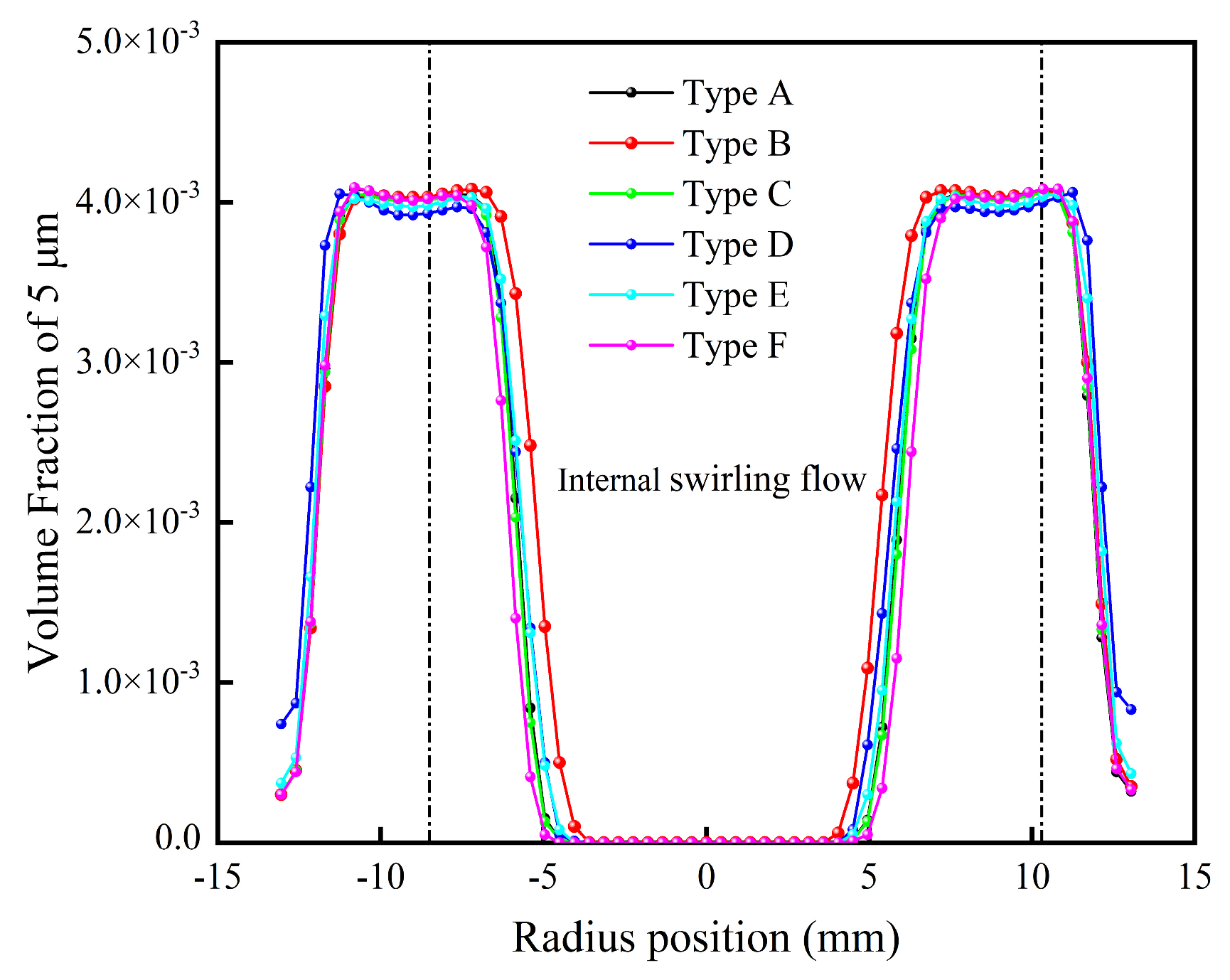
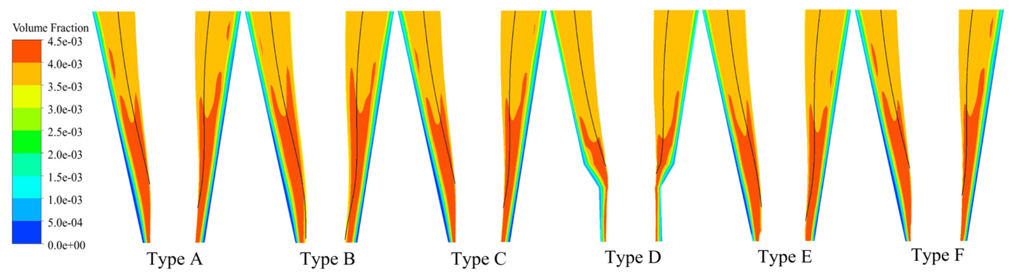
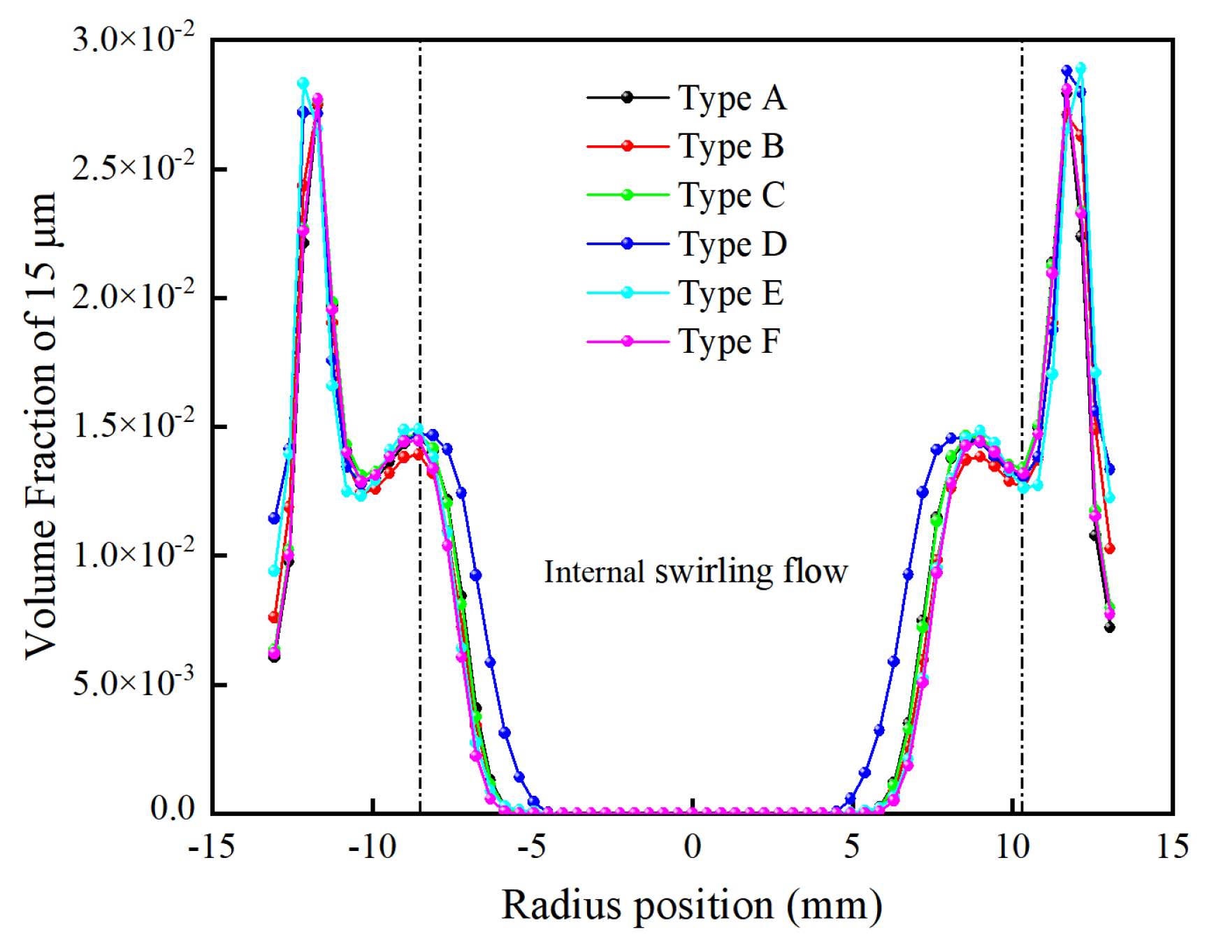
3.2.2. Particle Spatial Distribution

The spatial distribution of particles reflects the particle movement trend and enrichment rate and determines the size composition of the separation products. Figure 13 and Figure 14 show the spatial distribution of 5 μm and 15 μm particles, respectively, in the eigensection cloud diagrams under several structures. To better characterize the particle distribution, the data are processed by removing the air cone region with an air-phase volume fraction >95%, and the black line in the cloud diagrams is the location of the zero-velocity surface, which is used to differentiate between internal and external swirling flows. As shown in the figure, for 5 μm fine particles, Type D has the lowest enrichment rate in the bottom region, and Type B has the largest enrichment region within the zero-velocity surface; these are composed of particles with an upward axial velocity following the internal swirling flow into the overflow, and both structures contribute to the reduction in fine particle misplacement in the underflow. For 15 μm particles, Type D has a greater enrichment within the zero-velocity surface, which increases the chance for this particle size to enter the overflow and increases the separation cut size.
Figure 15 and Figure 16 show the spatial distribution curves of 5 μm and 15 μm particles at the typical height, respectively, by defining the radial position with an axial velocity of 0 m/s to differentiate between the internal and external swirling flow. As shown in the figure, the enrichment ratio of 5 μm particles in the internal swirling flow of Type B is the largest, with the highest enrichment efficiency occurring along the radial position. Similarly, the yield of fine-grained particles increases within the overflow product; while Type D is faster and enriches more 15 μm particles in the internal swirling flow, the overflow product becomes coarser.

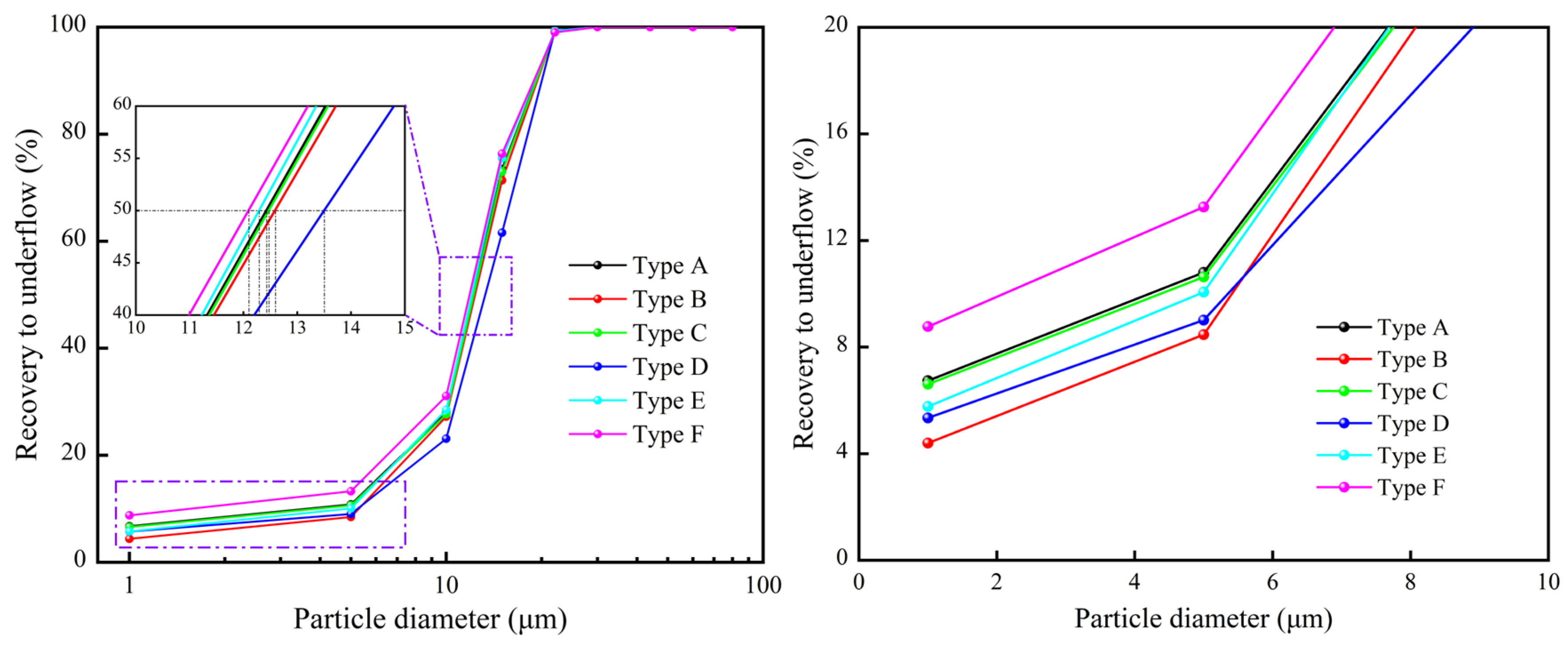
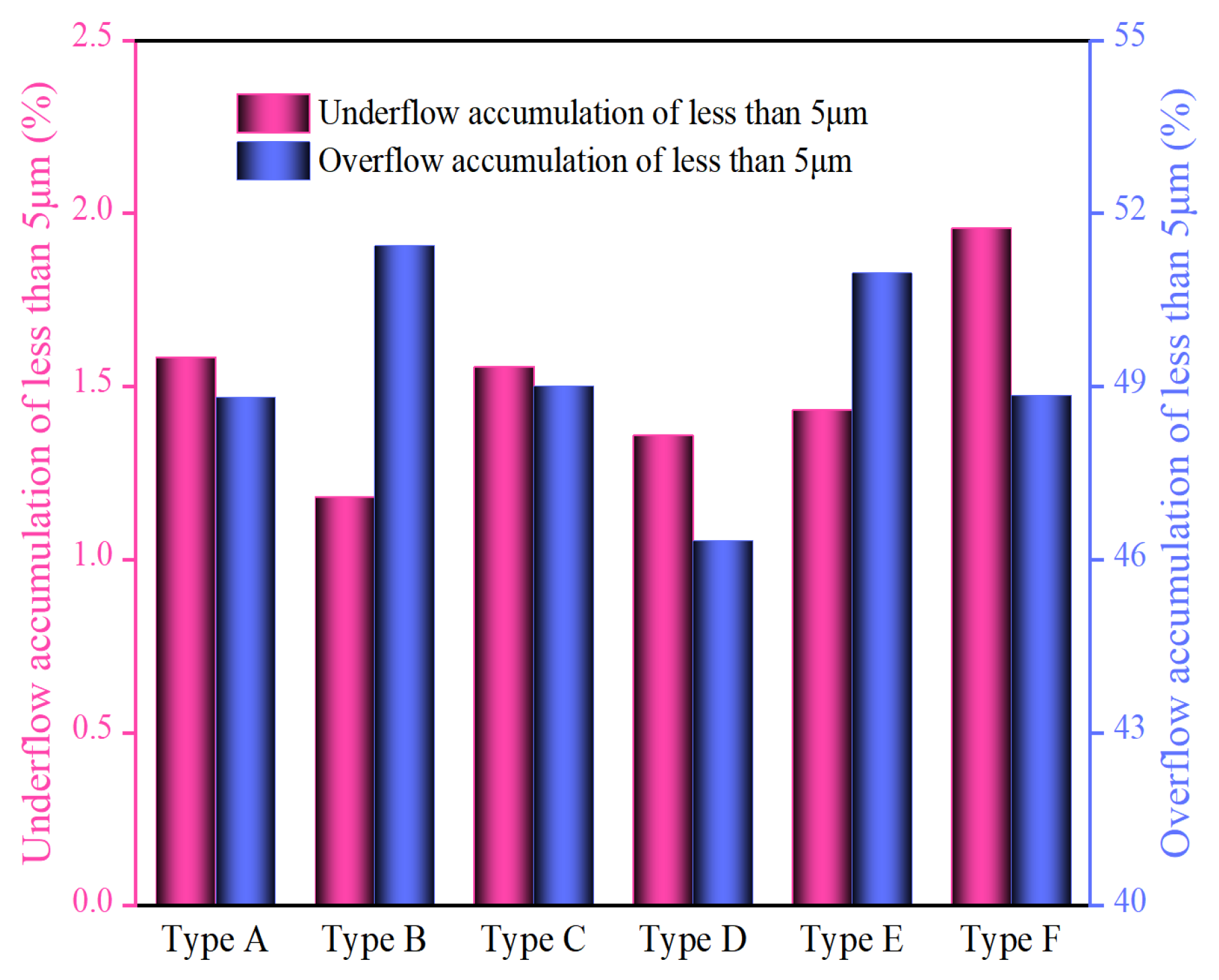
3.2.3. Separation Performance of Fine Particles

This paper selects 5 μm fine particles as characteristic particles to quantify the separation performance of hydrocyclones on fine particles. Figure 17 shows a comparison of the accumulation of particles less than 5 μm in underflow and overflows under several structures. Figure 18 shows the water distribution in the underflow and the integrated grading efficiency calculated from the particle content less than 5 μm. The water distribution of the underflow represents the water percentage of the total feed water in the underflow products, and the integrated grading efficiency reflects both the separation effect and the degree of particle misplacement of the outlet products in the separation process. The formula is
E = α θ β α α β θ 100 α × 10000 %
where α, β, and θ are the negative accumulations of the featured particle in the feed, overflow, and underflow, respectively.
As shown in the figure, compared with that in the regular Type A hydrocyclone, the water distribution in the underflow in Type B and Type D decreases by approximately 2.9%, while that in Type F increases by 2.1%. Usually, fine particles follow a fluid with a positive correlation with the water fraction. For the Type B hydrocyclone, the underflow contains the fewest particles less than 5 μm, which is 0.4% lower than that of Type A. Additionally, the content of particles less than 5 μm in the overflow increases by 2.6%, and the calculated integrated grading efficiency increases by 3.4%, which indicates that an elongated spigot structure contributes to reducing fine particle mismatch in the underflow, improving overflow quality. The fine particles in the Type D underflow also decrease, but the larger cone angle promotes the inward migration of particles, a relatively reduced percentage of fine particles in the overflow. Fine particle misplacement in underflow in Type F was aggravated, which indicated that the spigot structure of the anti-cone material without a cylinder section buffer lowered the resistance of fine particles downward, increased the chance for fine particles escaping through underflow, and decreased the integrated grading efficiency by 1.9%.

4. Conclusions

To alleviate fine particle misplacement in underflow, this study designs five new types of spigots; adopts the CFD method; calculates pressure, velocity, and turbulence fields as indexes to analyze the flow field distribution pattern; and calculates efficiency curves, particle spatial distribution, underflow water distribution, and integrated grading efficiency as indexes to quantify the separation performance, leading to the following conclusions:
(1) The large cone design of the Type D hydrocyclone slows the downward external swirling flow. It promotes the inward migration of particles, and the tangential and radial velocities within the hydrocyclone increase, which helps to strengthen the separation process and reduce the content of mismatched particles in underflow. In addition, the maximum tangential velocity trajectory surface shifts outward, the effective separation space decreases, the turbulent movement in the cone section becomes more intense, and the energy consumption of separation increases, which influences the separation accuracy.
(2) The Type B elongated-spigot hydrocyclone, which has a lower turbulence intensity and a smaller change gradient, reduces the disturbance turbulence to improve the separation accuracy, decreases the water distribution underflow, decreases the following effect of fine particles, and decreases the recovery ratio of 1 μm and 5 μm particles in underflow by 2.34% and 2.31%, respectively. Additionally, more fine particles are enriched in the internal swirling flow and increase the integrated grading efficiency by 3.4%, as calculated by the accumulation of particles less than 5 μm.
(3) The spigot structure affects fluid and particles’ downward motion and the air intake state through underflow, which has a significant impact on the distribution of the forced eddy field. A complicated spigot structure helps to increase the resistance of particle discharge and contributes to the alleviation of fine particle misplacement in underflow.

Author Contributions

Conceptualization, P.L. and D.H.; data curation, B.C.; investigation, P.L., B.C. and D.H.; methodology, P.L., B.C. and D.H.; software, B.C. and X.Y., supervision, W.Z., Y.L. and D.H.; writing—original draft, B.C.; writing—review and editing, P.L. and B.C.; validation, B.C. and X.Y.; funding, W.Z. and Y.L. All authors have read and agreed to the published version of the manuscript.

Funding

This research was funded by the LiaoNing Revitalization Talents Program, China (XLYC2204015).

Data Availability Statement

The raw data supporting the conclusions of this article will be made available by the authors on request.

Conflicts of Interest

Yuanli Lu was employed by the company Dandong Dongfang Measurement & Control Technology Co., Ltd. The authors declare that the research was conducted in the absence of any commercial or financial relationships that could be construed as a potential conflict of interest.

References

  1. da Silva, J.T.T.; Bicalho, I.C.; Ribeiro, G.P.; Ataíde, C.H. Hydrocyclone Applied in the Physical Processing of Phosphate Concentrate Containing Rare Earth Elements. Miner. Eng. 2020, 155, 106402. [Google Scholar] [CrossRef]
  2. Dai, L.; Xu, D.; Wei, A.; Shan, M.; Tao, P.; Deng, Z.; Li, J.; Chen, J.; Wang, H. Purification of Hydrogenated Oil by Microchannel Separation Coupling Hydrocyclone. Process Saf. Environ. Prot. 2023, 180, 981–991. [Google Scholar] [CrossRef]
  3. Zhang, C.; Lu, S. Study on the Separation Mechanism of Coal and Gangue Particles during Coal Slime Classification in a Hydrocyclone. Powder Technol. 2023, 424, 118566. [Google Scholar] [CrossRef]
  4. Khatri, N.; Khatri, K.K.; Sharma, A. Enhanced Energy Saving in Wastewater Treatment Plant Using Dissolved Oxygen Control and Hydrocyclone. Environ. Technol. Innov. 2020, 18, 100678. [Google Scholar] [CrossRef]
  5. Tang, Z.; Yu, L.; Wang, F.; Li, N.; Chang, L.; Cui, N. Effect of Particle Size and Shape on Separation in a Hydrocyclone. Water 2018, 11, 16. [Google Scholar] [CrossRef]
  6. Ji, L.; He, L.; Chu, K.; Kuang, S. How Particles with Sizes Close to Cut Size Affect the Multiphase Flows and Performance of Hydrocyclones. Ind. Eng. Chem. Res. 2021, 60, 18477–18489. [Google Scholar] [CrossRef]
  7. Gonçalves, S.M.; Ullmann, G.; Morimoto, M.G.; de Souza Barrozo, M.A.; Vieira, L.G.M. Effect of Rheology and Solids Concentration on Hydrocyclones Performance: A Study Involving the Design Variables of an Optimized Hydrocyclone. J. Pet. Sci. Eng. 2022, 210, 110019. [Google Scholar] [CrossRef]
  8. Zhang, Y.; Yang, M.; Liu, P. Sediment-Containing Sewage Separation Using Intermittent-Discharge Columnar Hydrocyclones. Water 2020, 12, 2883. [Google Scholar] [CrossRef]
  9. Palaniandy, S.; Yahyaei, M.; Powell, M. Assessment of Hydrocyclone Operation in Gravity Induced Stirred Mill Circuits. Miner. Eng. 2017, 108, 83–92. [Google Scholar] [CrossRef]
  10. Gonçalves, S.M.; Kyriakidis, Y.N.; Ullmann, G.; De Souza Barrozo, M.A.; Vieira, L.G.M. Design of an Optimized Hydrocyclone for High Efficiency and Low Energy Consumption. Ind. Eng. Chem. Res. 2020, 59, 16437–16449. [Google Scholar] [CrossRef]
  11. Izquierdo, J.; Sukunza, X.; Espinazo, P.; Vicente, J.; Aguado, R.; Olazar, M. In Depth Characterisation of Hydrocyclones: Ascertaining the Effect of Geometry and Operating Conditions on Their Performance. Adv. Powder Technol. 2023, 34, 104025. [Google Scholar] [CrossRef]
  12. Tian, J.; Ni, L.; Song, T.; Olson, J.; Zhao, J. An Overview of Operating Parameters and Conditions in Hydrocyclones for Enhanced Separations. Sep. Purif. Technol. 2018, 206, 268–285. [Google Scholar] [CrossRef]
  13. Cui, B.; Zhang, C.; Zhao, Q.; Hou, D.; Wei, D.; Song, T.; Feng, Y. Study on Interaction Effects between the Hydrocyclone Feed Flow Rate and the Feed Size Distribution. Powder Technol. 2020, 366, 617–628. [Google Scholar] [CrossRef]
  14. Pérez, D.; Cornejo, P.; Rodríguez, C.; Concha, F. Transition from Spray to Roping in Hydrocyclones. Miner. Eng. 2018, 123, 71–84. [Google Scholar] [CrossRef]
  15. Dubey, R.K.; Climent, E.; Banerjee, C.; Majumder, A.K. Performance Monitoring of a Hydrocyclone Based on Underflow Discharge Angle. Int. J. Miner. Process. 2016, 154, 41–52. [Google Scholar] [CrossRef]
  16. Su, T.; Zhang, Y. Effect of the Vortex Finder and Feed Parameters on the Short-Circuit Flow and Separation Performance of a Hydrocyclone. Processes 2022, 10, 771. [Google Scholar] [CrossRef]
  17. Ji, L.; Kuang, S.; Yu, A. Numerical Investigation of Hydrocyclone Feed Inlet Configurations for Mitigating Particle Misplacement. Ind. Eng. Chem. Res. 2019, 58, 16823–16833. [Google Scholar] [CrossRef]
  18. Jiang, L.; Liu, P.; Zhang, Y.; Li, X.; Yang, X.; Hou, D.; Chen, B. Effect of Cone Section Combination Form on the Separation Performance of a Biconical Hydrocyclone. Powder Technol. 2023, 419, 118325. [Google Scholar] [CrossRef]
  19. Dou, D.; Qiu, Z.; Yang, J. Parameter Optimization of an Industrial Water Injection Hydrocyclone in the Taixi Coal Preparation Plant. Int. J. Coal Prep. Util. 2022, 42, 2357–2365. [Google Scholar] [CrossRef]
  20. Kyriakidis, Y.N.; Silva, D.O.; Barrozo, M.A.S.; Vieira, L.G.M. Effect of Variables Related to the Separation Performance of a Hydrocyclone with Unprecedented Geometric Relationships. Powder Technol. 2018, 338, 645–653. [Google Scholar] [CrossRef]
  21. Silva, N.K.G.; Silva, D.O.; Vieira, L.G.M.; Barrozo, M.A.S. Effects of Underflow Diameter and Vortex Finder Length on the Performance of a Newly Designed Filtering Hydrocyclone. Powder Technol. 2015, 286, 305–310. [Google Scholar] [CrossRef]
  22. Ye, J.; Xu, Y.; Song, X.; Yu, J. Numerical Modelling and Multi-Objective Optimization of the Novel Hydrocyclone for Ultra-Fine Particles Classification. Chem. Eng. Sci. 2019, 207, 1072–1084. [Google Scholar] [CrossRef]
  23. Zhang, C.; Cui, B.; Wei, D.; Lu, S. Effects of Underflow Orifice Diameter on the Hydrocyclone Separation Performance with Different Feed Size Distributions. Powder Technol. 2019, 355, 481–494. [Google Scholar] [CrossRef]
  24. Yamamoto, T.; Oshikawa, T.; Yoshida, H.; Fukui, K. Improvement of Particle Separation Performance by New Type Hydro Cyclone. Sep. Purif. Technol. 2016, 158, 223–229. [Google Scholar] [CrossRef]
  25. Tian, J.; Ni, L.; Song, T.; Shen, C.; Yao, Y.; Zhao, J. Numerical Study of Foulant-Water Separation Using Hydrocyclones Enhanced by Reflux Device: Effect of Underflow Pipe Diameter. Sep. Purif. Technol. 2019, 215, 10–24. [Google Scholar] [CrossRef]
  26. Hou, D.; Cui, B.; Zhao, Q.; Wei, D.; Song, Z.; Feng, Y. Research on the Structure of the Cylindrical Hydrocyclone Spigot to Mitigate the Misplacement of Particles. Powder Technol. 2021, 387, 61–71. [Google Scholar] [CrossRef]
  27. Hou, D.; Zhao, Q.; Liu, P.; Jiang, L.; Cui, B.; Wei, D. Effects of Bottom Profile on the Circulation and Classification of Particles in Cylindrical Hydrocyclones. Adv. Powder Technol. 2023, 34, 104050. [Google Scholar] [CrossRef]
  28. Pathak, S.S.; Mishra, S.; Tyeb, M.H.; Majumder, A.K. Spigot Design Modification to Alleviate Roping in Hydrocyclones. Mining Metall. Explor. 2022, 39, 761–775. [Google Scholar] [CrossRef]
  29. Jiang, L.; Liu, P.; Yang, X.; Zhang, Y.; Wang, H. Designing W-Shaped Apex for Improving the Separation Efficiency of a Full-Column Hydrocyclone. Sep. Sci. Technol. 2020, 55, 1724–1740. [Google Scholar] [CrossRef]
  30. Jiang, L.; Liu, P.; Yang, X.; Zhang, Y.; Li, X.; Zhang, Y.; Wang, H. Experimental Research on the Separation Performance of W-Shaped Hydrocyclone. Powder Technol. 2020, 372, 532–541. [Google Scholar] [CrossRef]
  31. Han, T.; Liu, H.; Xiao, H.; Chen, A.; Huang, Q. Experimental Study of the Effects of Apex Section Internals and Conical Section Length on the Performance of Solid–Liquid Hydrocyclone. Chem. Eng. Res. Des. 2019, 145, 12–18. [Google Scholar] [CrossRef]
  32. Vega-Garcia, D.; Cilliers, J.J.; Brito-Parada, P.R. CFD Modelling of Particle Classification in Mini-Hydrocyclones. Sep. Purif. Technol. 2020, 251, 117253. [Google Scholar] [CrossRef]
  33. Liu, L.; Zhao, L.; Reifsnyder, S.; Gao, S.; Jiang, M.; Huang, X.; Jiang, M.; Liu, Y.; Rosso, D. Analysis of Hydrocyclone Geometry via Rapid Optimization Based on Computational Fluid Dynamics. Chem. Eng. Technol. 2021, 44, 1693–1707. [Google Scholar] [CrossRef]
  34. Li, Y.; Tao, S.; Song, X.; Zhao, Y. Study on Internal Flow Characteristics of Hydrocyclone with Guide Vanes. Sustainability 2023, 15, 5350. [Google Scholar] [CrossRef]
  35. Vysyaraju, R.; Pukkella, A.K.; Subramanian, S. Computational Investigation of a Novel Hydrocyclone for Fines Bypass Reduction. Powder Technol. 2022, 395, 501–515. [Google Scholar] [CrossRef]
  36. Jing, J.; Zhang, S.; Qin, M.; Luo, J.; Shan, Y.; Cheng, Y.; Tan, J. Numerical Simulation Study of Offshore Heavy Oil Desanding by Hydrocyclones. Sep. Purif. Technol. 2021, 258, 118051. [Google Scholar] [CrossRef]
  37. Durango-Cogollo, M.; Garcia-Bravo, J.; Newell, B.; Gonzalez-Mancera, A. CFD Modeling of Hydrocyclones-A Study of Efficiency of Hydrodynamic Reservoirs. Fluids 2020, 5, 118. [Google Scholar] [CrossRef]
  38. Zhang, C.; Wei, D.; Cui, B.; Li, T.; Luo, N. Effects of Curvature Radius on Separation Behaviors of the Hydrocyclone with a Tangent-Circle Inlet. Powder Technol. 2017, 305, 156–165. [Google Scholar] [CrossRef]
  39. Fang, X.; Wang, G.; Zhong, L.; Qiu, S.; Wang, D. Adaptability Analysis of Operating Parameters of Hydrate Hydrocyclone Separator Based on a CFD Simulation. Sep. Sci. Technol. 2022, 57, 979–989. [Google Scholar] [CrossRef]
  40. Padhi, M.; Mangadoddy, N.; Sreenivas, T.; Vakamalla, T.R.; Mainza, A.N. Study on Multi-Component Particle Behaviour in a Hydrocyclone Classifier Using Experimental and Computational Fluid Dynamics Techniques. Sep. Purif. Technol. 2019, 229, 115698. [Google Scholar] [CrossRef]
  41. Vakamalla, T.R.; Mangadoddy, N. The Dynamic Behaviour of a Large-Scale 250-Mm Hydrocyclone: A CFD Study. Asia-Pacific J. Chem. Eng. 2019, 14, e2287. [Google Scholar] [CrossRef]
  42. Liu, P.; Fu, W.; Jiang, L.; Zhang, Y.; Li, X.; Yang, X.; Chen, B. Effect of Back Pressure on the Separation Performance of a Hydrocyclone. Powder Technol. 2022, 409, 117823. [Google Scholar] [CrossRef]
Figure 1. Structural diagram of hydrocyclone.
Water 16 01070 g001
Figure 2. Local sizing of spigots.
Water 16 01070 g002
Figure 3. Mesh independence test of tangential velocity.
Water 16 01070 g003
Figure 4. WALL Y Plus of mesh.
Water 16 01070 g004
Figure 5. Comparison of static pressure.
Water 16 01070 g005
Figure 6. Comparison of pressure drop.
Water 16 01070 g006
Figure 7. Comparison of tangential velocity distribution.
Water 16 01070 g007
Figure 8. Comparison of radial velocity distribution.
Water 16 01070 g008
Figure 9. Comparison of axial velocity distribution.
Water 16 01070 g009
Figure 10. Comparison of the spatial distribution of turbulence intensity.
Water 16 01070 g010
Figure 11. Comparison of the spatial distribution of turbulent eddy dissipation.
Water 16 01070 g011
Figure 12. Comparison of separation efficiency.
Water 16 01070 g012
Figure 13. Comparison of spatial distribution of 5 μm particle volume fraction.
Water 16 01070 g013
Figure 14. Comparison of spatial distribution of 15 μm particle volume fraction.
Water 16 01070 g014
Figure 15. Comparison of volume fraction of 5 μm.
Water 16 01070 g015
Figure 16. Comparison of volume fraction of 15 μm.
Water 16 01070 g016
Figure 17. Comparison of particle accumulation of less than 5 μm in underflow and overflow.
Water 16 01070 g017
Figure 18. Comparison of water distribution and integrated grading efficiency of less than 5 μm.
Water 16 01070 g018
Table 1. Structure parameters of hydrocyclone.
Structure ParametersSize
Diameter of cylinder section, D (mm)75
Diameter of inlet, a × b (mm)10 × 26
Height of body, H (mm)320
Height of outer vortex finder, H1 (mm)40
Height of cylinder section, H2 (mm)90
Height of cone section, H3 (mm)170
Cone angle (°)20
Diameter of vortex finder, do (mm)25
Insertion depth of vortex finder, h (mm)50
Diameter of spigot, ds (mm)15
Table 2. Distribution of feed particle size.
Size Interval (μm)Mean Size (μm)Yield (%)Volume Fraction (%)
0–214.350.174
2–758.470.339
7–12109.940.398
12–181512.340.494
18–252218.180.727
25–353015.790.632
35–504414.330.573
50–70609.830.393
70–90806.770.271
Table 3. Comparison of separation performance.
Type AType BType CType DType EType F
d50 (μm)12.512.712.513.612.411.9
Ep (μm)3.20 3.25 3.15 3.60 3.15 3.15
I0.256 0.256 0.252 0.265 0.254 0.252
Disclaimer/Publisher’s Note: The statements, opinions and data contained in all publications are solely those of the individual author(s) and contributor(s) and not of MDPI and/or the editor(s). MDPI and/or the editor(s) disclaim responsibility for any injury to people or property resulting from any ideas, methods, instructions or products referred to in the content.

