Article

Study on Water Inflow Variation Law of No.1 Shaft Auxiliary Shaft in HighLiGongshan Based on Dual Medium Model

1
Key Laboratory of Urban Underground Engineering, Ministry of Education, Beijing Jiaotong University, Beijing 100044, China
2
School of Civil Engineering, Beijing Jiaotong University, Beijing 100044, China
*
Author to whom correspondence should be addressed.
Symmetry 2021, 13(6), 930; https://doi.org/10.3390/sym13060930
Submission received: 25 April 2021 / Revised: 13 May 2021 / Accepted: 18 May 2021 / Published: 24 May 2021

Abstract

:
When the fracture is not developed and the connectivity is poor, the original single medium simulation cannot meet the accuracy requirements. Now, the seepage simulation of fractured rock mass has gradually developed from equivalent continuous medium to dual medium and multiple medium. However, it is still difficult to establish the connection between a discrete fracture network model and a continuous medium model, which makes it difficult to simulate the influence of fracture location on the seepage field of rock mass. As the excavation direction of the shaft is vertically downward, the surrounding strata are symmetrical around the plane of the shaft axis, which is different from the horizontal tunnel. Taking the auxiliary shaft of the No.1 Shaft in HighLiGongshan as the engineering background, combined with Monte Carlo methods and DFN generator built in FLAC3D5.01, a discrete fracture network is generated. Based on the dual medium theory, MIDAS is used to optimize the modeling of each fracture group. At the same time, the concept of “Fracture Weakening area” is introduced, and the simulation is carried out based on a fluid–solid coupling method. It is found that the simulation effect is close to the reality. The water inflow increases with the increase of shaft excavation depth, and the water inflow at the end of excavation is nearly three times larger than the initial value. Combined with Legendre equation, a new analytical formula of water inflow prediction is proposed. It is found that this analytical formula is more sensitive to permeability and has a greater safety reserve.

1. Introduction

A proper mathematical model must be established for fracture simulation. The commonly used mathematical models include the equivalent porous media model, the discrete fracture network model and the dual medium model. Long j.c.s., Junyi Gao, Hongjiang Chen et al. have studied the seepage-stress coupling and the seepage-heat coupling of fractured rock mass by using the equivalent porous media model [1,2,3,4,5,6,7,8,9]. The results show that the equivalent porous media model is more suitable for the fractured rock mass with the representative elementary volume (REV), but not for the large fracture with low density, and it is unable to simulate the preferential flow characteristics of fracture. Jinli Wang studied the fractured rock mass by using the discrete fracture network model [10], and found that the simulation effect of this method is better when the fracture connectivity is good and the fracture data is clear, but there are difficulties in data acquisition and connectivity evaluation. The dual media model can be divided into a narrow dual media model and a broad dual media model. Dong Yang and Chen He have studied the generalized double medium model and developed the corresponding software [11,12], but the modeling method and the establishment of the equivalent formula at the intersection are difficult, as it is not widely used. Guanglin Du, Enzhi Wang, J. rutqvist., etc., adopted the narrow dual medium model [13,14,15,16,17,18,19,20,21,22,23], established the seepage continuity equation through the principle of flow equivalence between fractures and pores, and carried out the corresponding research on the seepage model of fractured rock mass, and found that the simulation is difficult, but the effect is good.
The traditional double medium network simulation mostly uses the simple superposition of two kinds of media, ignoring the influence of fracture location, which has certain errors. With the development of computer technology, people gradually begin to study the construction of three-dimensional fracture networks. Compared with a 2D network, a 3D network considers the strike and dip angle of fractures, which makes the research more practical [24]. Now, the most commonly used method of 3D fracture network construction is the Monte Carlo method. With the deepening of research, it was proved that this method can well simulate the actual fracture network [25,26,27,28,29,30,31]. In addition, there are the LHS [32] method, random polygon method [33], spatial analysis method of deteriorated rock mass [34], artificial neural network method [35,36], etc.
The current water inflow prediction methods generally include: water balance method, runoff modulus method and analytical method. Analytical method and numerical simulation method are the most commonly used. Jian Wu, Zaixing Li and Xiaolong Li put forward corresponding improvements on the basis of the original analytical method [37,38,39,40,41,42,43,44,45], and the improved prediction formula is more in line with the reality. Zhi He, Yuchuan Tang and Longlin Wang analyzed the applicability of numerical methods under different projects by means of numerical simulation [46,47,48,49,50,51,52,53,54,55,56,57]. It is found that both analytical method and numerical method can achieve a certain prediction effect.
The HighLiGongshan fractures belong to a steep and large fracture, so it is not suitable to adopt the theory of equivalent continuous medium. In addition, it is found that the connectivity of the fracture group is not good according to the spot investigation data. There are a large number of closed fractures, so the discrete fracture network model is also not suitable. In this paper, based on the dual medium theory, combined with the spot measured fracture group data, the corresponding data are generated by Monte Carlo methods. At the same time, the original fracture data are further discretized with the help of a FLAC3D5.01 built-in DFN plug-in to obtain the actual fracture network. The double medium theory is used for numerical simulation, and a water inflow prediction formula based on the general solution of Legendre equation is derived. It is found that the prediction result is more in line with the reality.
Considering that the distribution of fracture strike conforms to Gaussian distribution, there is symmetry to a certain extent. In addition, the shaft support is symmetrical about the axis in the horizontal direction, and it is excavated symmetrically in sections in the axial direction. Different from the tunnel, the stratum around the shaft is a vertical and downward semi-wireless space body with the surface as the interface, and the stratum around the shaft is symmetrical about the axis of the shaft. The research based on the research background of No.1 Shaft auxiliary shaft has certain symmetrical reference meanings for the subsequent construction of the No.2 Shaft nearby. The research ideas of this paper are as follows in Figure 1.

2. Seepage Simulation of Fractured Rock Mass Based on Fluid Structure Coupling Method

2.1. Engineering Background

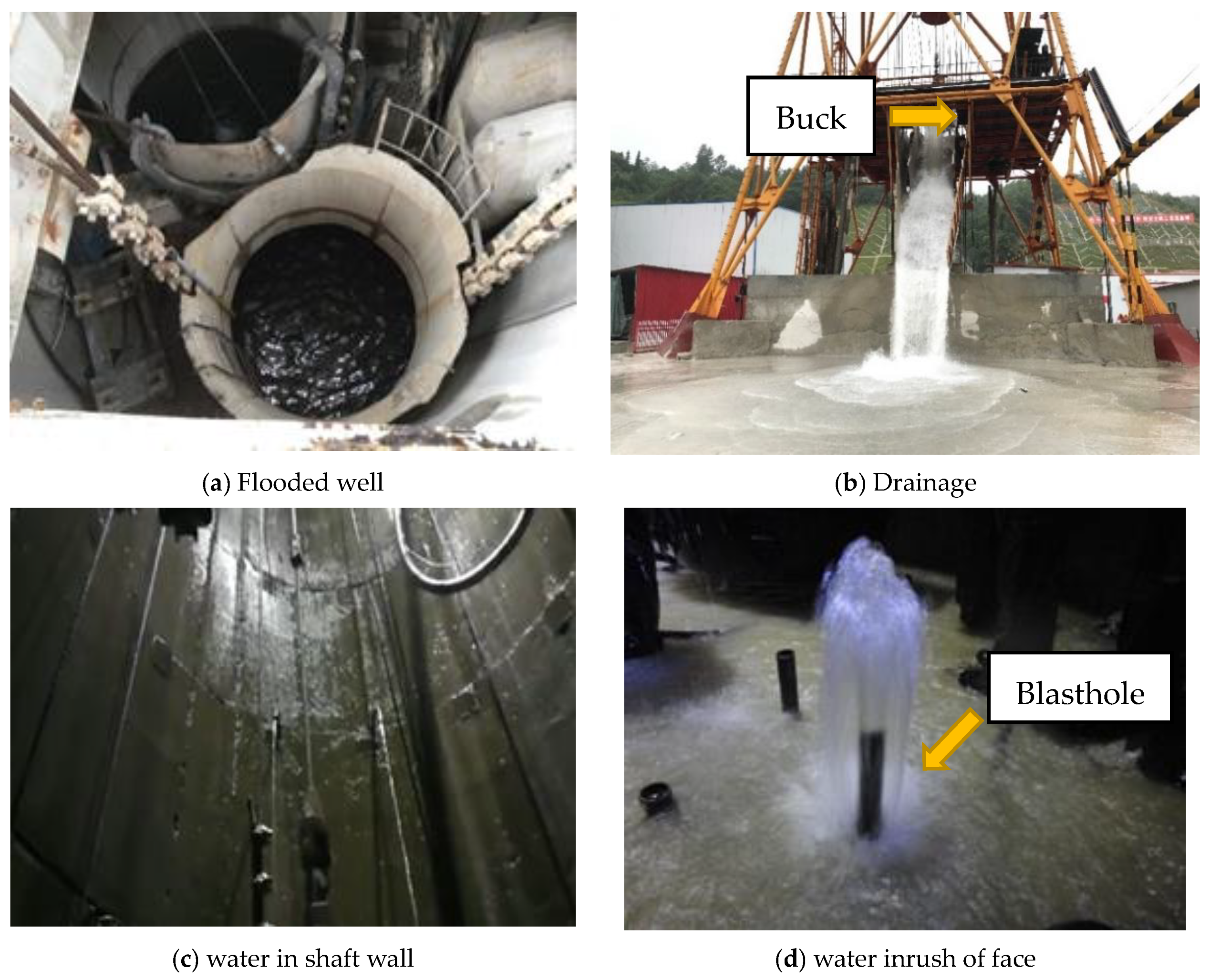
The auxiliary tunnel of HighLiGongshan tunnel is set as ‘one through horizontal guide + one inclined shaft + two vertical shafts’, in which the auxiliary shaft of one vertical shaft is 764.74 m deep and the inner diameter of the auxiliary shaft is 5.0 m. After the completion of the auxiliary shaft, it is used for feeding, fresh air, drainage, moving personnel in and out, and also as a safety exit. At about 19:00 on 15 January 2018, the depth of the auxiliary shaft was 630.3 m. In the process of mucking out and leveling, the side of the shaft on the left side of the line suddenly collapsed, forming a ‘bowl shaped’ gushing point. The water inflow was about 300 m3/h, causing well flooding. See Figure 2a,b for the spot pictures. On 19 January 2018, Yun Gui railway company held an expert meeting. Through analysis, it was concluded that the complex hydrogeological conditions around the shaft, the sudden water inflow on the side of the shaft and the inability to accurately predict the water inflow were the main reasons for this well flooding. The water inflow of on-site engineering mainly included water gushing from the shaft wall and working face, as shown in Figure 2c,d.
Due to the complex geological conditions, water inrush often occurs, and Party A decided to carry out the corresponding research. This research belongs to one of the sub topics. This research has carried on the detailed simulation and the corresponding theoretical formula derivation for the shaft water inflow problem. It is found that the power of pumping equipment should be further strengthened. Figure 3 shows the proposed drainage equipment.

2.2. Geological Conditions

The stratum exposed by the borehole is granite with an exposed thickness of 771.43 m. The lithology is mainly composed of light gray green, light gray, dark gray and light gray black granite. According to the exposed stratum thickness and core, the rock cores are dense, massive, hard, complete, locally broken, closed to micro tensional fracture, medium coarse grain metamorphic structure, grain size ranging from 0.4 to 3 cm, mainly composed of quartz and mica, locally weakly weathered, and locally vertical fracture the distribution and fracture surface show yellowish brown ferromanganese infection, and local fracture surface shows sandy muddy filling.

2.3. Hydrologic Condition

According to the survey data of the No.1 Shaft supplementary exploration hole of HighLiGongshan tunnel, the logging contents include conventional logging (apparent resistivity, spontaneous potential, natural gamma, gamma gamma), inclinometer and temperature logging. Four aquifers are determined from the logging curve, which are 154.50–156.25 m, 340.00–343.70 m, 495.45–498.90 m and 693.50–694.75 m. Other non-water bearing fracture zones are 440.60–442.25 m, 459.05–461.40 m, 470.95–473.85 m and 480.05–483.90 m.

2.4. Establishment of Discrete Fracture Network

In rock mechanics, the Monte Carlo method is often used to generate a random fracture network with the same distribution as the actual rock fracture in the statistical sense. The main process is: (1) collecting rock fracture parameters; (2) statistical analysis of fracture data; (3) generating random fracture network. The fractures of different depth exposed by grouting excavation in HighLiGongshan are shown in Figure 4.
In view of the bad spot environment, the data of the fracture group are mainly obtained through a segmented drilling experiment, with the drilling depth of 771 m and 66 sections. According to the recent research results and engineering practice on the geometric distribution of rock fractures, the geometric parameters of rock fractures generally follow one or several probability density distributions. Generally speaking, the location of fracture center points obeys uniform distribution; the trace length obeys negative exponential distribution or lognormal distribution; the occurrence usually obeys univariate or bivariate Fisher distribution, bivariate normal distribution or lognormal distribution, etc. Combined with the actual engineering background of HighLiGongshan, it is considered that the engineering fracture components are divided into three groups, the center point conforms to the uniform distribution, the trace length conforms to the normal distribution, the occurrence conforms to the normal distribution, and the density of the three groups is similar. The statistical fracture data are shown in Table 1.
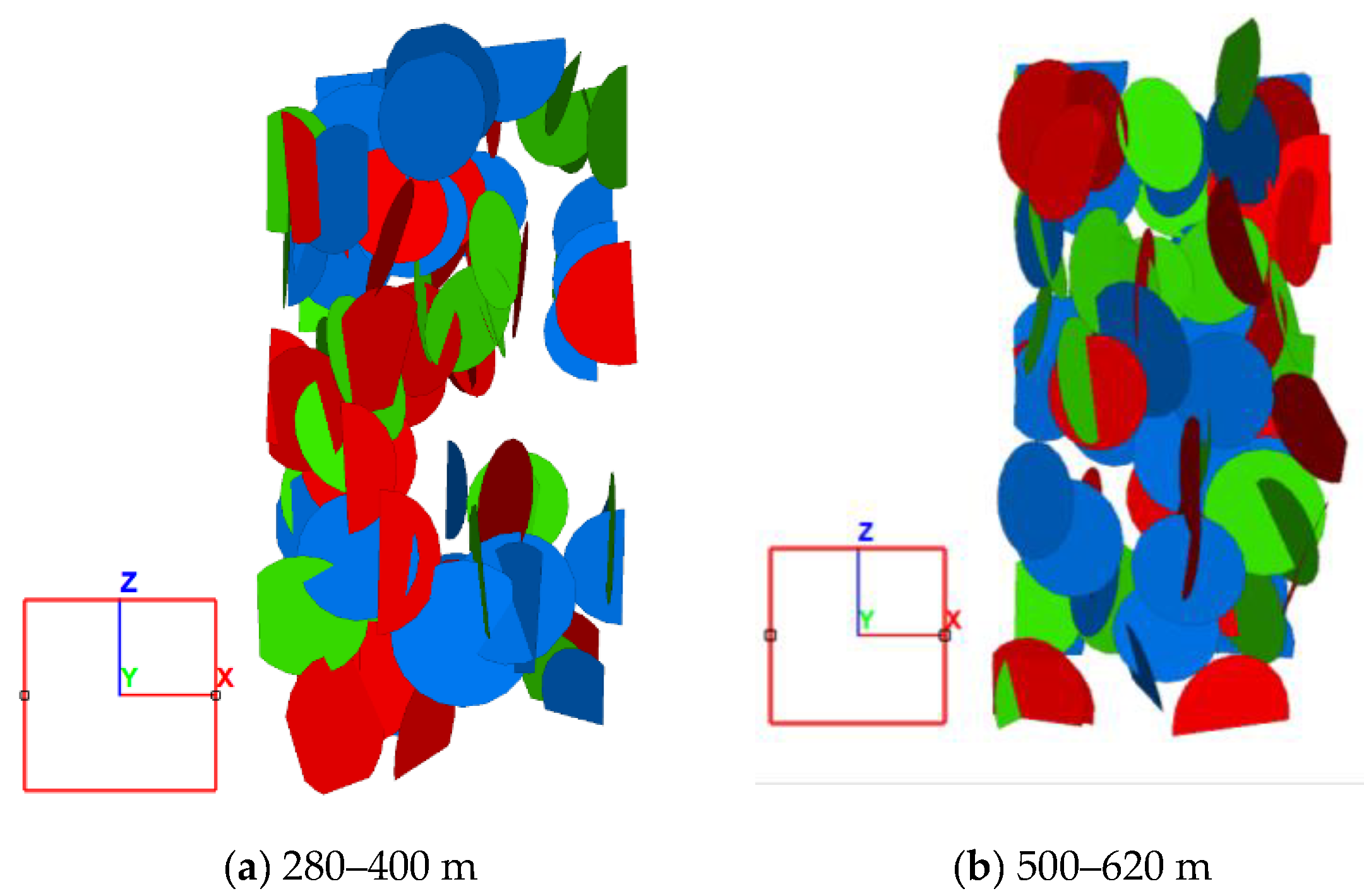
The (0,1) random number of uniform distribution is obtained by using the linear congruence method. The geometric characteristics of fractures can be obtained through the obtained characteristic function. For convenience, 30 fractures are selected for each group. In order to ensure the randomness of fractures, the fracture template data obtained by Monte Carlo methods are input into a FLAC3D5.01 built-in DFN program for further discretization, and the fracture network generated is shown in Figure 5.

2.5. Establishment of Dual Medium Model

The concept of “fracture weakening zone” is introduced. The original fracture is simulated by the “fracture weakening zone”. It is considered that the part of rock mass closely connected with long and large fractures is the “weakening zone”, affected by fractures. The fluid flow in this area is dominated by fracture water, and the flow rate is approximately equal to the flow rate of fracture water. This part of rock mass is used to simulate the original fractures. In order to prove the rationality of this hypothesis, two models are adopted, one is simulated by the actual fracture width, and the other is simulated by two groups of elements contacting the fracture surface, as shown in Figure 6.
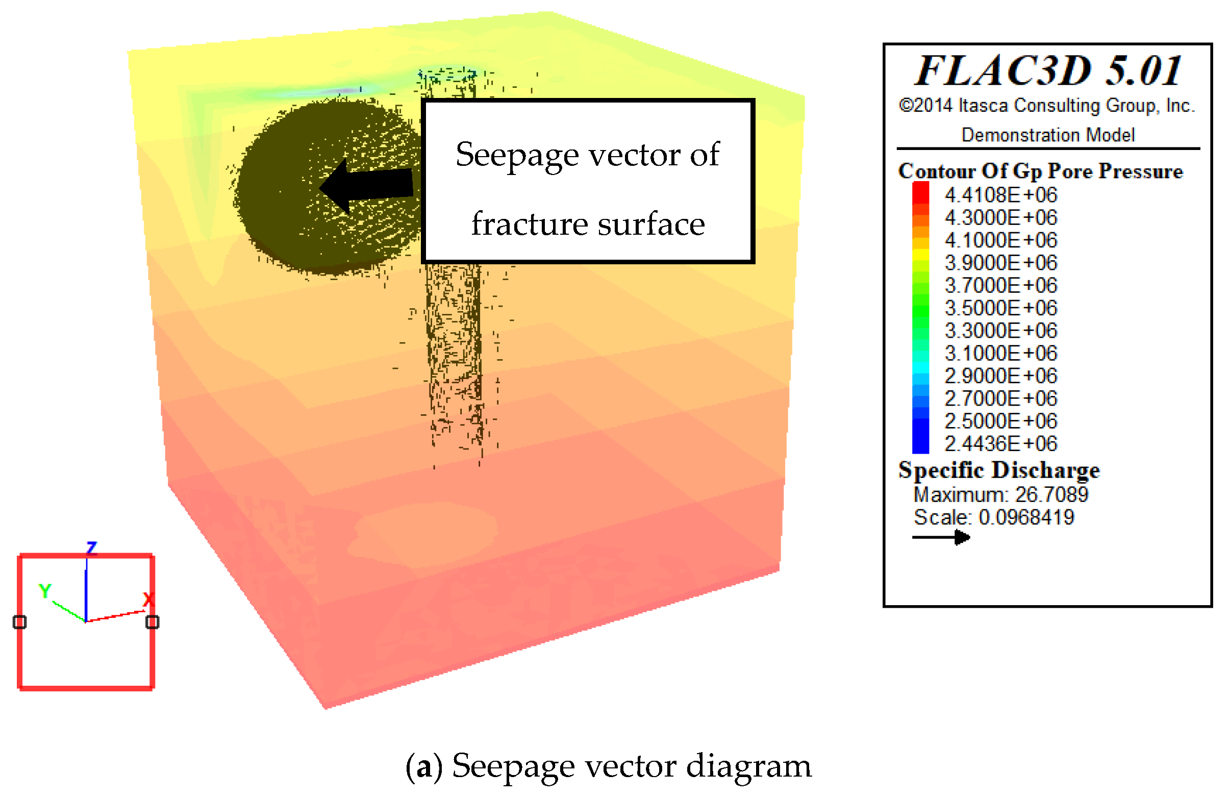
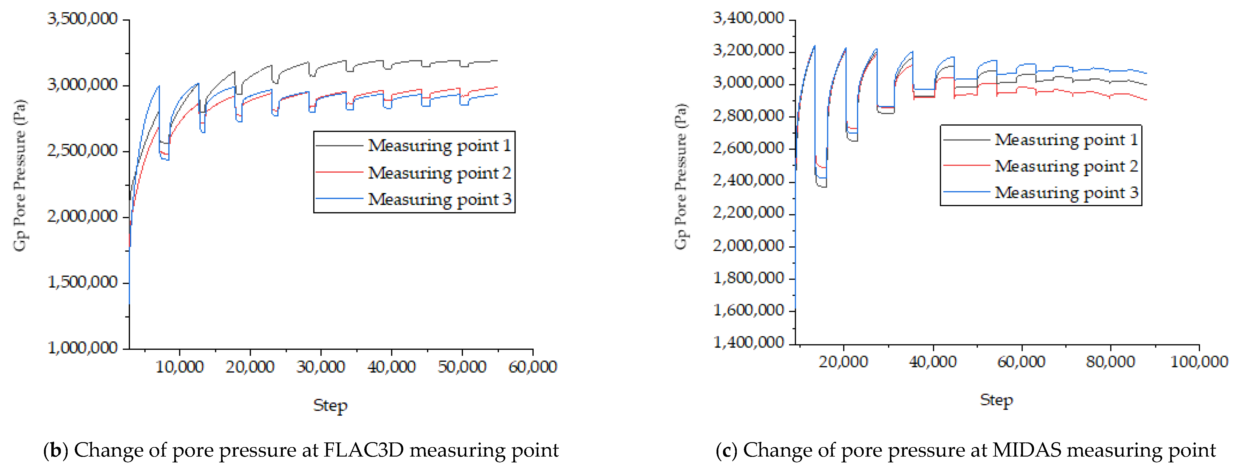
Three measuring points are taken on the fracture surface to monitor the change of pore water pressure during excavation. The seepage vector diagram is shown in Figure 7a, and the monitoring data of the measuring points are shown in Figure 7b,c.
Through Figure 7a, it is found that the fluid flow in this area is dominated by fracture water, and the flow rate is approximately equal to that of fracture water. Comparing the monitoring data, it is found that there is only a certain error in the water pressure between the two methods, but the variation law is almost the same, as shown in Figure 7. Therefore, we think this method meets the accuracy requirements of the original fracture simulation.
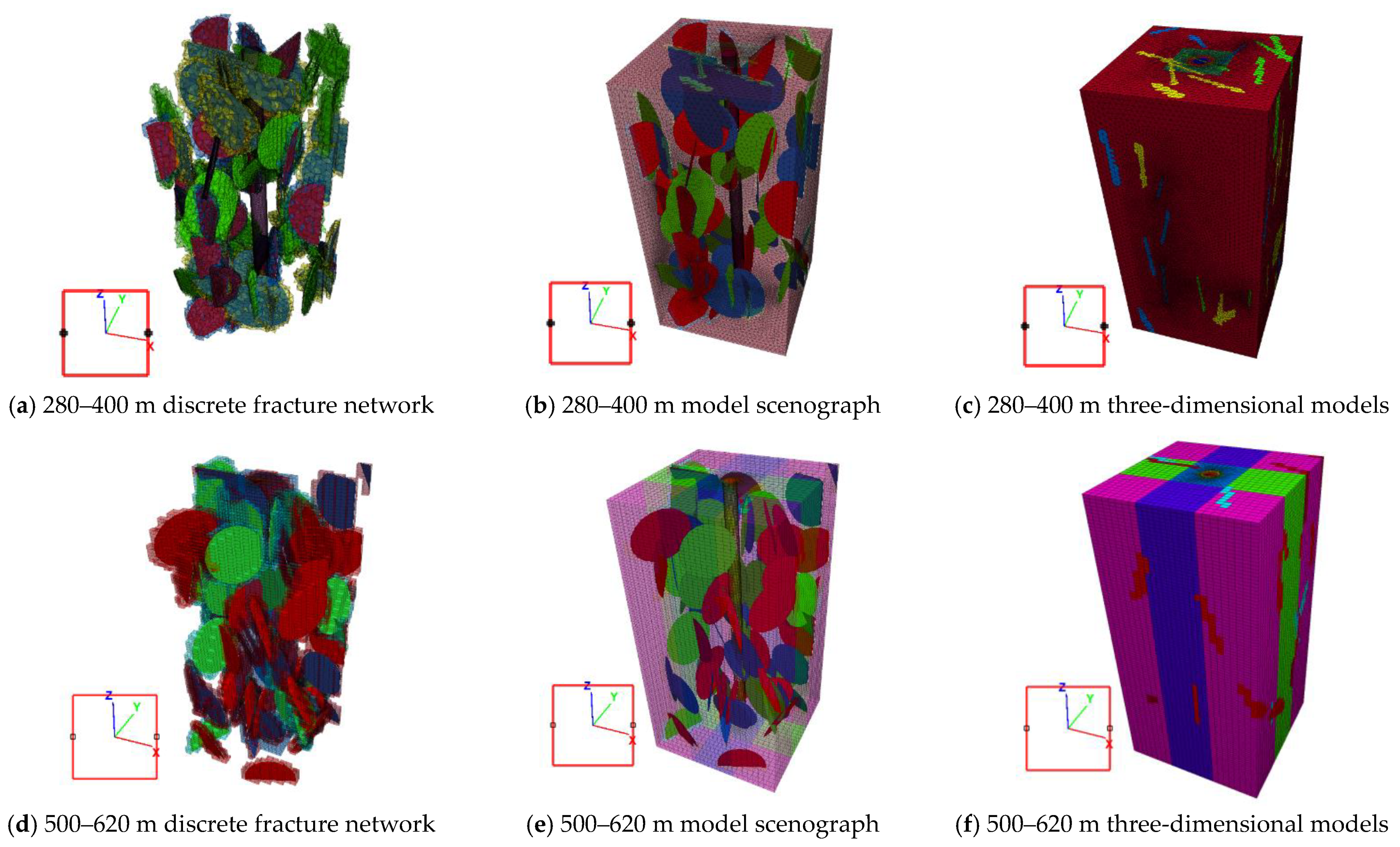
The diameter of the auxiliary shaft of the No.1 Shaft in HighLiGongshan is 5 m. Considering the effective range of construction influence, the plane size of the model is 60 m × 60 m. As the depth of the shaft is about 770 m, considering the calculation speed of the computer, only the typical joint development depth is simulated. Combined with the spot investigation data, it is concluded that the fracture characteristics of 280~400 m and 500~620 m sections are obvious, and most of them belong to the above three groups of fractures, so a large-scale finite difference model is established based on these three sections. In addition, each fracture is accurately located through the existing fracture network. As for the introduction of the fracture network, the existing discrete network data is exported, and the fracture network is simulated by using the fine modeling function of MIDAS software. Considering the computer calculation speed and the difficulty of grid division, only the representative fractures of each group are accurately simulated, and the concept of a “fracture weakening area” is used for coarse simulation of the remaining fractures. The geological parameters of each section are shown in Table 2 and Table 3.
The geological parameters of fracture group are shown in Table 4.
Unlike rock matrix, the seepage of fracture water is anisotropic. The seepage tensor of the three groups of fractures is obtained by Formula (1).
K = i = 1 n K i [ 1 cos 2 α i sin 2 φ i sin α i sin 2 φ i cos α i cos α i sin φ i cos φ i sin α i sin 2 φ i cos α i 1 sin 2 α i sin 2 φ i sin α i sin φ i cos φ i cos α i sin φ i cos φ i sin α i sin φ i cos α i 1 cos 2 φ i ]
See Table 5 for the main value of the seepage tensor.
The shaft excavation method is a drilling–blasting method, the grouting radius is 0.6 R, the excavation footage is 3.6 m, the support form is anchor mesh support, and cable element simulation is used. Considering the grouting excavation and non-grouting excavation, the interaction between MIDAS and FLAC3D is used to establish a total of four models, as shown in Figure 8, which are 1.4 million units and 660,000 units, respectively. In the model, the porous medium is symmetrical.
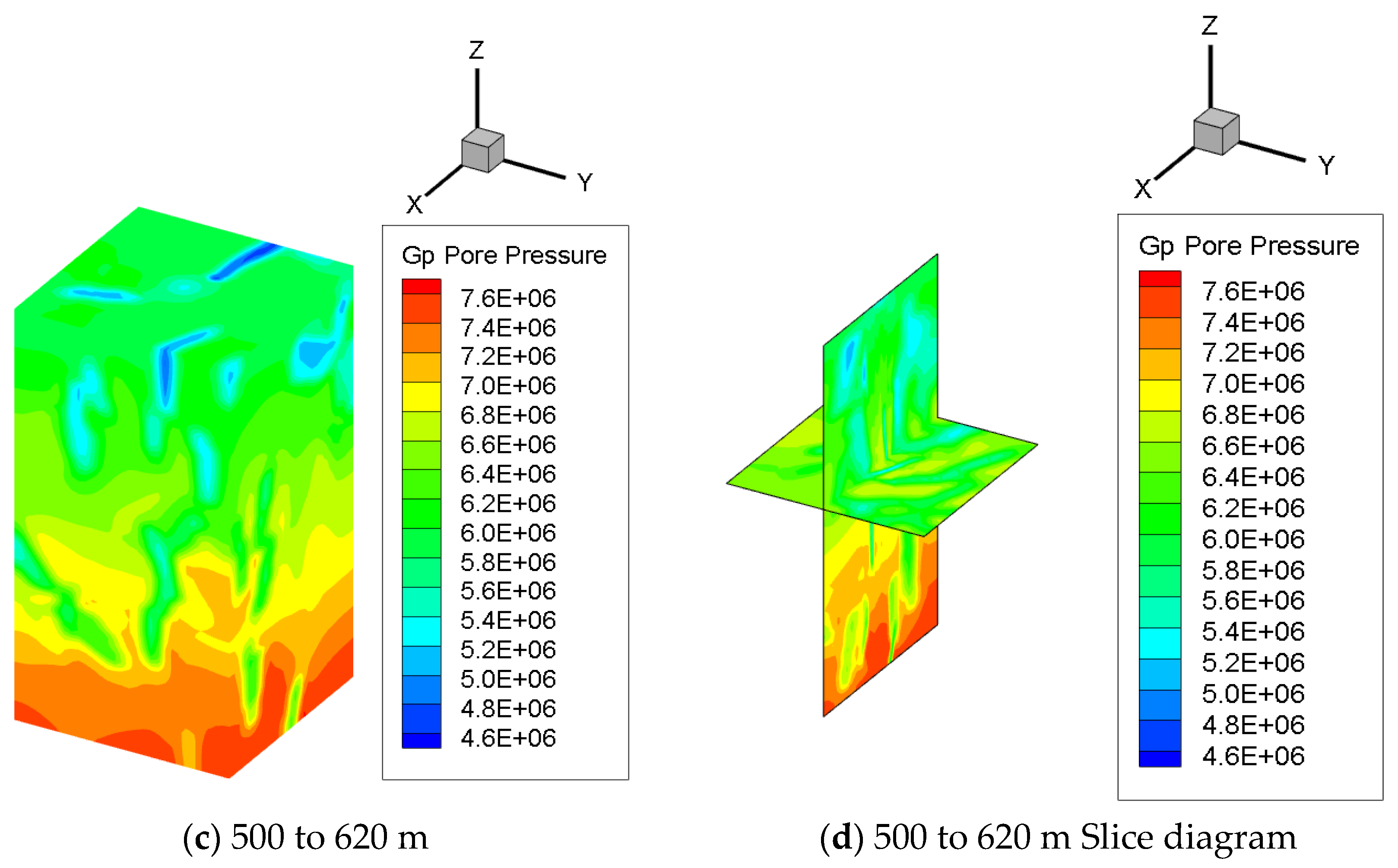
After the in situ stress is balanced and output by Tecplot, as shown in Figure 9, it can be seen that the existence of fractures weakens the surrounding pore water pressure.

3. Site Pumping Test

3.1. Construction Plan

The wireline coring drilling tool is used for the combination construction of the survey hole. The coreless drilling tool is used to drill to the complete rock, and the coring bit is used to drill to the final hole. The geophysical logging is carried out, and the pumping test is carried out one by one in the aquifer. The equipment includes a deep well submersible pump (model: 100QJ2-150/60), which pumps water for four times. According to the pumping time, it is divided into the fourth aquifer, the third aquifer, the second aquifer and the first aquifer.

3.2. Experimental Data

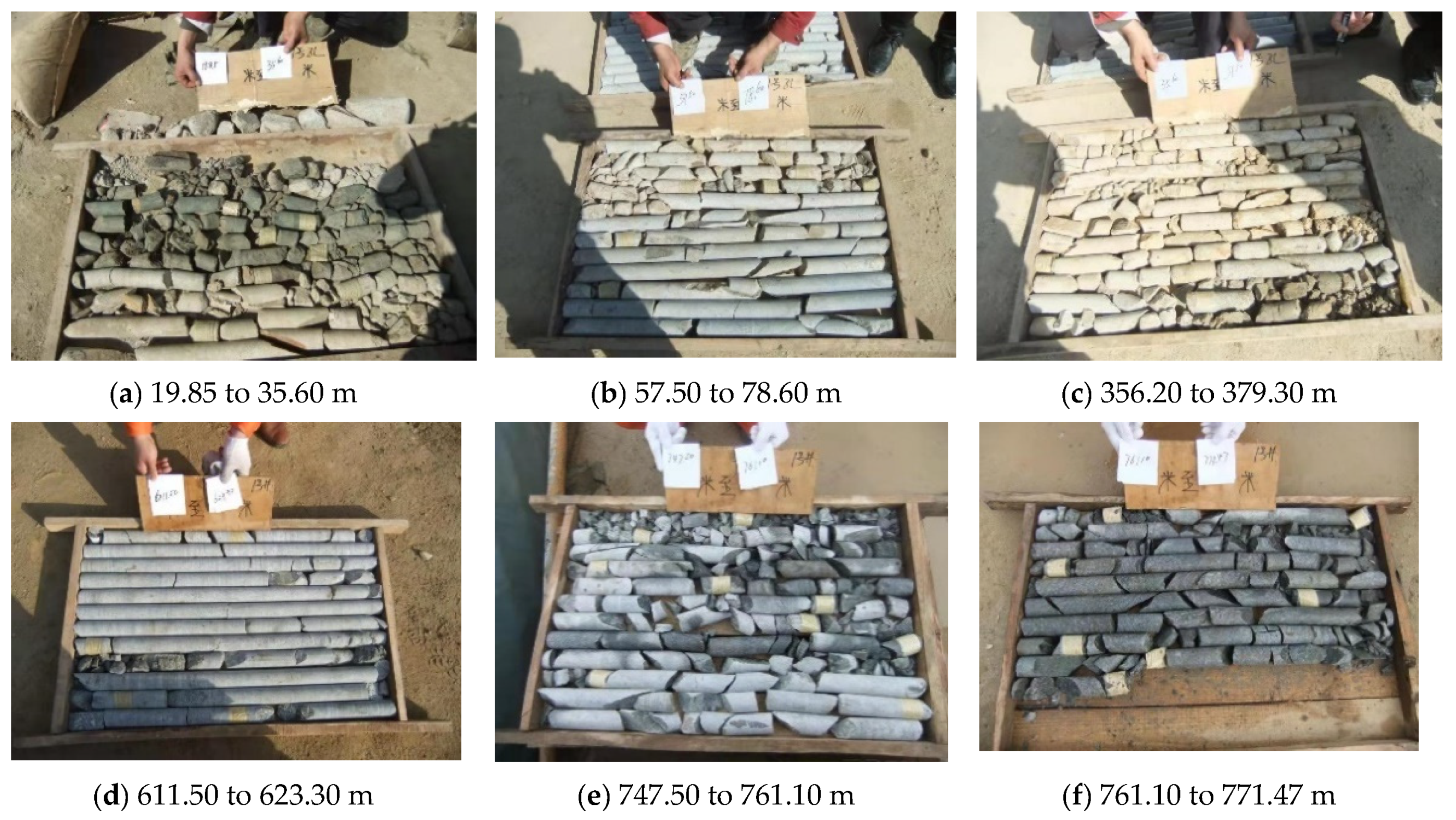
Some drilling samples are shown in Figure 10.
The pumping test data are shown in Table 1, which uses the maximum drawdown depth of the water level in the well only, and the hydrogeological parameters are calculated by Formula (2). The predicted value of water inflow calculated by Formula (3) is shown in Table 2.
Q = 2.73 K M s w lg R r w R = 10 s w K ( Stable   Joule   Formula )
where Q is the single well water field, K is the permeability coefficient, M is the aquifer thickness, r w is the water level in well, 0.0455 m in this calculation, S w is the average water level draw down in stable section, and R is the radius of influence.
Q = 1.366 K [ ( 2 H 0 M ) M h 2 ] lg R r w R = 10 s w K ( Formula   of   Pressure   to   No   Pressure )
where Q is the average water inflow of stable section, K is the permeability coefficient, M is the aquifer thickness, h is the water level in well, s w is the average water level draw down in stable section, R is the radius of influence, and H 0 is the height from static water level of the aquifer to the aquifer floor (see Table 6 and Table 7).

4. Derivation of Water Inflow Prediction Formula

4.1. Basic Assumption

The strata are homogeneous porous media.
(1)
The seepage conforms to Darcy’s law, that is, the seepage velocity in a certain direction is proportional to the hydraulic gradient.
(2)
The permeability coefficient of the rock stratum is the same in all directions.
(3)
Study only steady flow (time independent).
(4)
The influence radius is 2 H, and H is the distance from the still water surface to the bottom of the well [58].
(5)
The seepage field accords with Dupuit hypothesis.

4.2. Formula Derivation

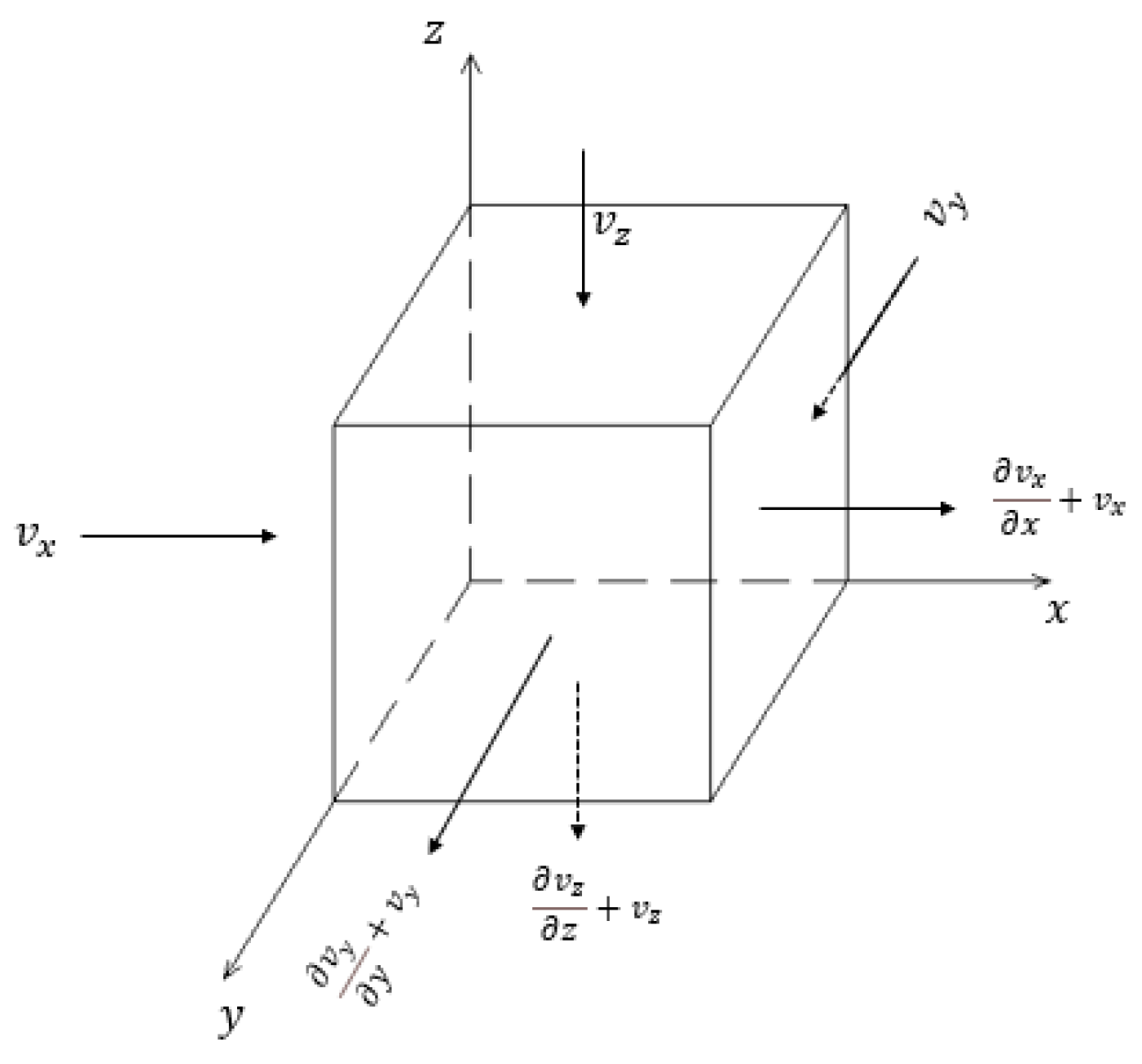
Let there be a differential element in the seepage field, as shown in Figure 11. The side length is d x , d y , d z , and the velocity v x , v y , v z is a function of the coordinates. The flow rate into the unit is v x , v y , v z . The flow velocity of the outflow unit is:
v x x d x + v x ,   v y y d y + v y ,   v z z d z + v z
It is considered that the fluid in the flow channel cannot be compressed, and the inflow flow of the unit is equal to the outflow flow. Then, it can be shown that
v x d y d z + v y d x d z + v z d x d y = ( v x x d x + v x ) d y d z + ( v y y d y + v y ) d x d z + ( v z z d z + v z ) d x d y .
i.e.,
v x x + v y y + v z z = 0 .
Darcy’s law is introduced:
v x = K h x , v y = K h y , v z = K h z .
There K is the permeability coefficient and h stand for the full head
Substituting Formula (5), we get
h 2 x 2 + h 2 y 2 + h 2 z 2 = 0 .
The equation expressed by column coordinate:
1 r r ( r h r ) + 1 r 2 2 h θ 2 + 2 h z 2 = 0 .
The seepage flow in the affected area of shaft excavation is considered to be symmetrical about the z axis, that is, Equation (8) is expressed as:
1 r r ( r h r ) = 0 .
i.e.,
2 h r 2 + 1 r h r = 0 .
As there is only one variable, PDE is converted to an ordinary differential equation as follows:
d 2 h d r 2 + 1 r d h d r = 0 .
The solution of separated variables is as follows:
J = d h d r = Q 2 π r K .
The integral of Equation (12) is as follows:
h = Q 2 π K ln r + a .
Using spherical coordinates to express Equation (5), we can get
1 r 2 r ( r 2 h r ) + 1 r 2 sin θ θ ( sin θ h θ ) + 1 r 2 sin θ 2 h φ 2 = 0 .
Take h ( r , θ , φ ) = u ( r ) ( θ , φ ) = u ( r ) c ( θ ) ϕ ( φ ) . Substituting Equation (14), after twice separating the variables, the following formula is obtained:
{ r 2 d 2 u d r 2 + 2 r d u d r η u = 0 1 sin θ d d θ ( sin θ d c d θ ) + ( η λ sin 2 θ ) c = 0 d 2 ϕ d φ 2 + ρ ϕ = 0 μ = l ( l + 1 ) ρ = m 2 .
The seepage in the area affected by shaft excavation is considered to be symmetrical around the z-axis, i.e.; ρ = m 2 = 0 , which leads to
{ r 2 d 2 u d r 2 + 2 r d u d r l ( l + 1 ) u = 0 1 sin θ d d θ ( sin θ d c d θ ) + l ( l + 1 ) c = 0 .
Take b = cos θ , i.e.,
{ r 2 d 2 u d r 2 + 2 r d u d r l ( l + 1 ) u = 0 ( 1 b 2 ) d 2 p ( b ) d b 2 2 b d p ( b ) d b + l ( l + 1 ) p ( b ) = 0 .
The general solution is as follows:
{ u ( r ) = c 1 r l + c 2 r l + 1 p l ( b ) = 1 2 l l ! d l ( b 2 1 ) l d b 2 ( l = 0 , 1 , 2 , 3 , , n ) .
The general solution of h is as follows:
h = l = 0 + ( c l r l + b l r l + 1 ) 1 2 l l ! d l ( b 2 1 ) l d b 2 ( l = 0 , 1 , 2 , 3 , , n ) .
The general series solution of Legendre equation is as follows
y = ( a 0 y 1 + a 1 y 2 ) y 1 = 1 l ( l + 1 ) 2 ! x 2 + l ( l 2 ) ( l + 1 ) ( l + 3 ) 4 ! x 4 +   , y 2 = x ( l 1 ) ( l + 2 ) 3 ! x 3 + ( l 1 ) ( l 3 ) ( l + 2 ) ( l + 4 ) 4 ! x 5 +
because of
| b | = | cos θ | 1
Formula (19) has the following form:
h = l = 0 + ( c l r l + b l r l + 1 ) ( a 0 y 1 + a 1 y 2 ) ( l = 0 , 1 , 2 , 3 , , n ) y 1 = 1 l ( l + 1 ) 2 ! x 2 + l ( l 2 ) ( l + 1 ) ( l + 3 ) 4 ! x 4 + . y 2 = x ( l 1 ) ( l + 2 ) 3 ! x 3 + ( l 1 ) ( l 3 ) ( l + 2 ) ( l + 4 ) 4 ! x 5 +
Based on the assumption of the radius of influence of the shaft pumping, there are
Outside   the   ball : h 1 = l = 0 + ( a l r l + b l r l + 1 ) P l ( b ) ( l = 0 , 1 , 2 , 3 , , n )   In   the   ball : h 2 = l = 0 + ( c l r l + d l r l + 1 ) P l ( b ) ( l = 0 , 1 , 2 , 3 , , n ) .
Considering the boundary conditions, the equation is established as follows
{ h 1 = l = 0 + ( a l r l + b l r l + 1 ) P l ( b ) ( l = 0 , 1 , 2 , 3 , , n ) h 2 = l = 0 + ( c l r l + d l r l + 1 ) P l ( b ) ( l = 0 , 1 , 2 , 3 , , n ) h 1 | r = Q 2 π K ln r + a b l | r = 1 d l | r = 0 .
When r ± , then θ 0 b = cos θ 1 . Therefore, replacing it with cylindrical coordinates, we can get
h 1 = l = 0 + ( a l r l ) P l ( b ) l = 0 + ( a l r l ) a 0 = Q 2 π K ln r + a ( l = 0 , 1 , 2 , 3 , , n ) .
On the ball, d l = 0 because of r = 0 . Therefore, h 2 has the following form:
h 2 = l = 0 + ( c l r l ) P l ( b ) ( l = 0 , 1 , 2 , 3 , , n ) .
It is considered that if the influence radius of shaft pumping is 2 s w , ( 2 s w , H ) is a common point. From this point { h 1 = h 2 v 1 = v 2 K 1 = K 2 J 1 = J 2 , we can get
{ [ Q 2 π K ln ( R 0 ) + a ] P 1 ( b ) + l = 2 + ( b l r l + 1 ) P l ( b ) = l = 0 + ( c l r l ) P l ( b ) Q 2 π K 1 R 0 P 1 ( b ) l = 2 + ( 2 b l r l + 2 ) P l ( b ) = l = 0 + ( l c l r l 1 ) P l ( b ) .
i.e.,
{ Q 2 π K ln ( R 0 ) + a + b 1 R 0 2 P 1 ( b ) = c 1 R 0 Q 2 π K 1 R 0 2 b 1 R 0 3 = c 1 .
From this formula, we can get
{ b 1 = R 0 2 3 ( Q 2 π K a Q 2 π K ln R 0 ) c 1 = Q 2 π K 1 R 0 Q 3 π K + R 0 3 b n = c n = 0 , n 1 R 0 = 2 s w .
The general solution of the original equation is
h = c 1 P 1 ( b ) .
Due to b = cos θ = d h d r , a Dupuit hypothesis is adopted, which leads to
h = c 1 P 1 ( b ) = c 1 cos θ = c 1 d h d r = c 1 d r d h .
After separating variables, we can get
{ H 0 2 ( H 0 s w ) 2 = ( 2 H 0 s w ) s w = 2 c 1 ( R 0 r 0 ) c 1 = Q 2 π K 1 R 0 Q 3 π K + R 0 3 R 0 = 2 s w .
The results are as follows:
Q = 2 π s w 2 K ( 6 H 0 11 s w + 4 r 0 ) ( 2 s w r 0 ) ( 3 4 s w ) .
where Q is the well discharge per linear meter at depth H 0 , K is the permeability coefficient, s w is the average water level draw down in stable section, r 0 is the waste path of the well, and H 0 is the ground water level at rest.

5. Result

5.1. The Prediction Results of This Formula Are Compared with Those of the Original Big Well Method

The results of this formula are shown in Table 8.
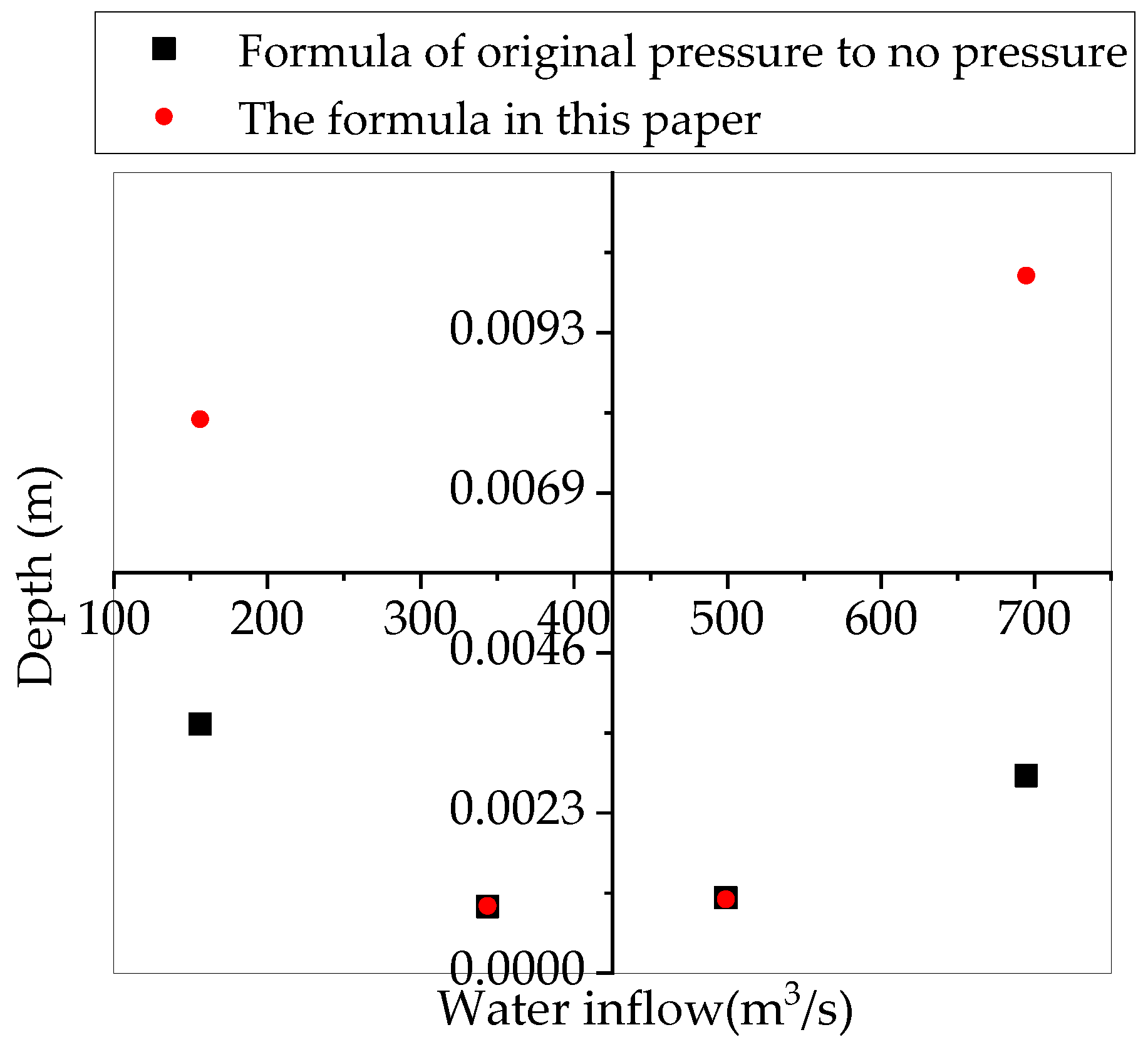
The comparison of the calculation results of the formula in this paper and that of the big well method is shown in Figure 12.
Through comparison, it is found that the change of permeability coefficient in the formula derived in this paper is more sensitive. In the area with small permeability coefficient, the calculation results in this paper are very close to those calculated by the formula of pressure to no pressure. In the aquifer with large permeability coefficient, the calculation result of this formula is obviously larger than that of big well method, which has a greater safety reserve.

5.2. Variation Law of Water Inflow in Working Face during Shaft Excavation

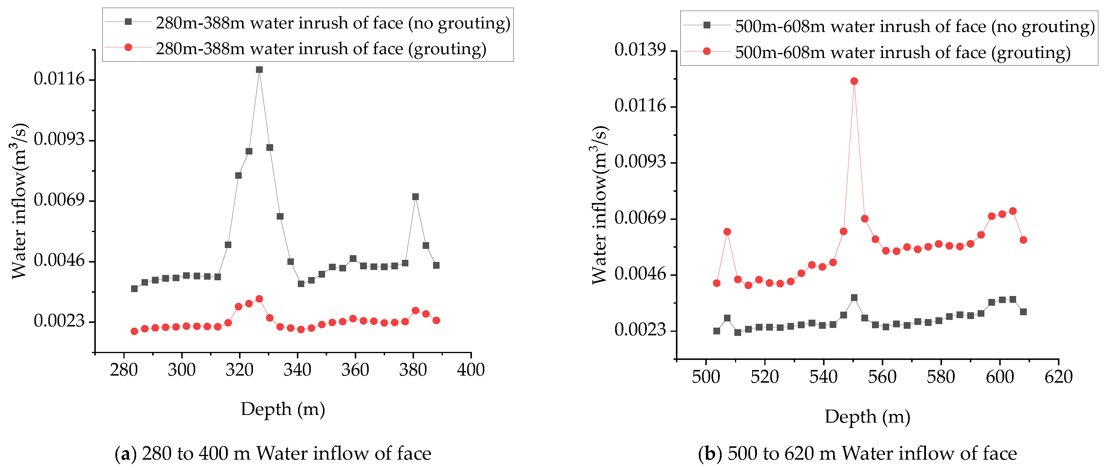
It can be seen from the variation law of the monitoring curve in the Figure 13 that if the joint surface is exposed during the excavation process, the water inflow will increase by multiple, and the maximum will increase to half an order of magnitude. With the advancement of the working face, after passing through the fracture area, the water inflow of the working face will gradually fall back to the normal value, and it is in direct proportion to the excavation depth of the shaft. In addition, the simulation grouting effect is obvious, the water inflow of the working face is greatly reduced, and the water inflow basically presents the trend of stable increase with the shaft excavation, and the increase range is small. Compared with the growth rate of water inflow of the 280–400 m working face, the growth rate of water inflow of the 500–620 m working face increases significantly, which reflects that, with the increase of shaft excavation depth, the change rate of water inflow of working face increases gradually.

5.3. Variation Law of Shaft Wall Water Inflow during Shaft Excavation

From the monitoring data in Figure 14, it can be found that the water inflow of the shaft wall increases with the increase of depth basically. The deeper the excavation depth is, the greater the increase is. When the fracture area is exposed, the water inflow of shaft wall increases to a certain extent, but the amplitude is relatively smaller than that of the working face. Combined with Figure 13, it can be found that the normal water inflow of the working face within 280–400 m is similar to that of the shaft wall, and the normal water inflow of the working face within 500–620 m is relatively smaller than that of the shaft wall. With the excavation depth, the proportion of the shaft wall water inflow to the total water inflow gradually increases from 50% to about 70%, and the proportion of shaft wall water inflow to the total water inflow is proportional to the excavation depth of the shaft. Combined with the daily discharge data, this result is in line with the reality.

5.4. Variation Law of Total Water Inflow during Shaft Excavation

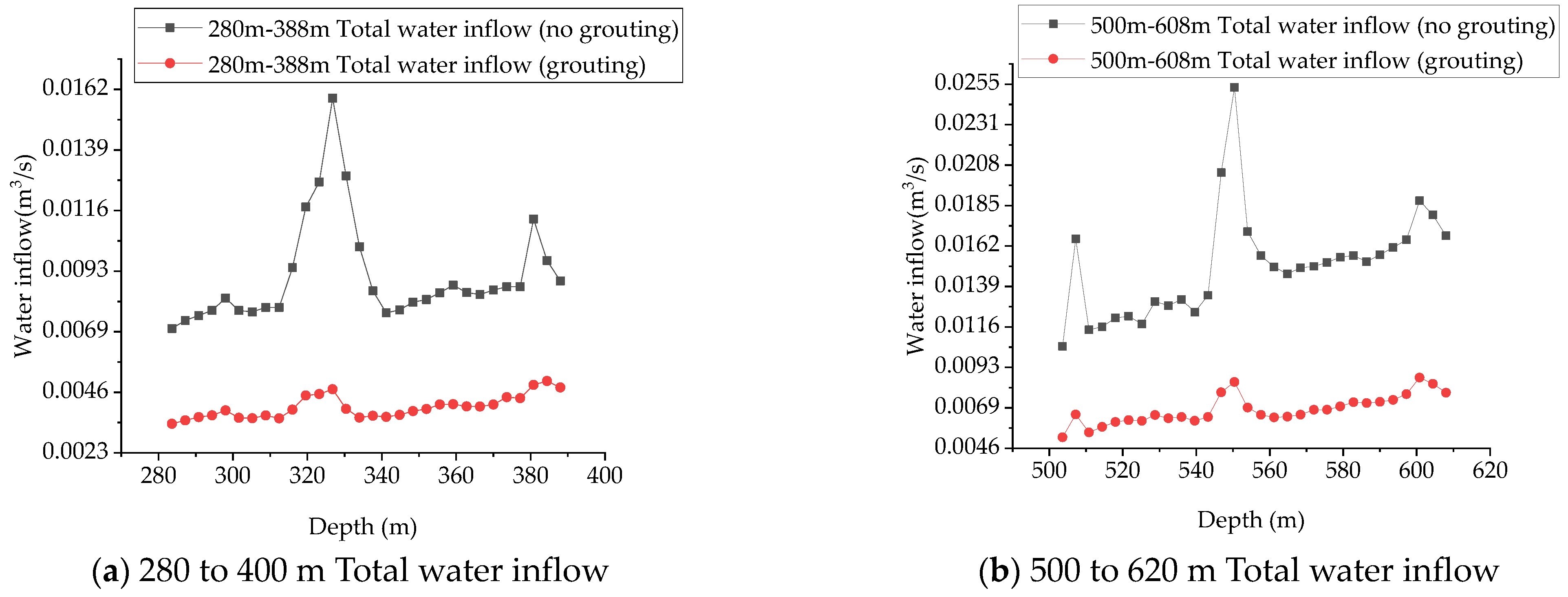
From the monitoring data in Figure 15, it can be found that grouting in the fracture area can obviously avoid the risk of flooding caused by the rapid increase of water inflow due to the exposure of joint surface. When the fracture area is exposed by excavation, the total water inflow of the shaft increases about 2–3 times, and tends to be normal after passing through the fracture area, which is proportional to the excavation depth. With the increase of the excavation depth of the shaft, the variation range of the normal total water inflow inside the shaft gradually increases, and the variation range of 500–620 m is about 1.3 times of 280–400 m. Sufficient drainage measures should be prepared at the project site.

5.5. Comparative Analysis of Simulation, Theory and Measurement.

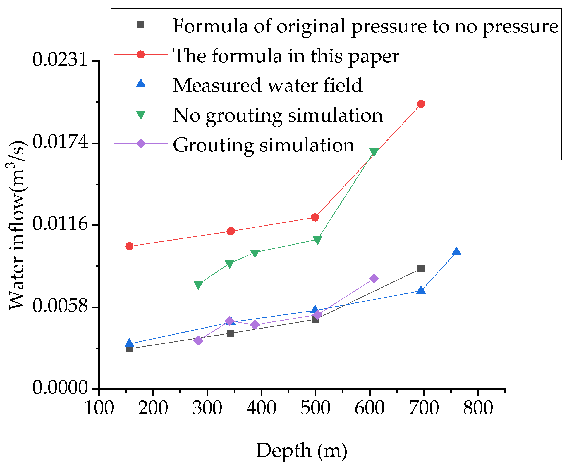
As the simulation depth is 280–400 m and 500–620 m, the normal total water inflow values with excavation depth of 283.6 m, 341.2 m, 388 m, 503.6 m and 608 m are taken. As the grouting method has been used in the actual project, the measured value is the water inflow after grouting excavation. It can be found from Figure 16 that the grouting simulation results are close to the field measured results, but far less than the simulation results without grouting, so the simulation effect is better. The calculation result of the original pressure to non-pressure formula is too small to meet the requirement of the safety reserve. The calculation formula in this paper is close to the simulation result of no grouting, and is closer to the actual excavation result of no grouting compared with the original pressure bearing to no pressure calculation result.

6. Conclusions

(1)
The simulation results of the proposed seepage model of fractured rock mass are in good agreement with the reality, which can better reflect the influence of the existence of fractures on the changes of pore pressure and water inflow. The existence of fractures will weaken the pore pressure field around, which is about 0.3 times of the pore pressure field of porous media.
(2)
Comparing the simulation results of grouting and non-grouting, it is found that the water inflow of grouting excavation is significantly reduced compared with that of non-grouting excavation, especially when passing through the area where the fracture is located. Compared with the monitoring data of the total water inflow in different stages, it is found that the total water inflow increases sharply when passing through the fracture area, and decreases after passing. With the progress of excavation, the total water inflow presents a decreasing trend, with the increase of shaft excavation depth, the change rate of normal total water inflow in shaft increases gradually, which is consistent with the monitoring data.
(3)
Compared with the theoretical calculation results, the grouting simulation results are more close to the measured water inflow, and the numerical simulation method is a good means for construction in complex water rich areas. Compared with the formula of original pressure to no pressure, the water inflow prediction formula proposed in this paper is more sensitive to the permeability coefficient, and the calculated results are larger, so it has greater safety reserves.
(4)
With the progress of excavation, the total water inflow of shaft increases, and the difference of water inflow before and after excavation is nearly three times. Meanwhile, the proportion of shaft wall water inflow to the total water inflow gradually increases from 50% to about 70%, and the proportion of shaft wall water inflow to the total water inflow is proportional to the excavation depth of the shaft.
(5)
The formula presented in this paper is applicable to the engineering with symmetrical structure and horizontal stratum such as shaft. Further research is needed for tunnel engineering. At present, the prediction of steady flow water inflow is gradually improving, and the numerical simulation and analytical solution can accurately predict the project water inflow. However, it is still difficult to predict the water inflow of a kind of unsteady flow, such as water inrush.

Author Contributions

Conceptualization, Y.W. and J.L.; data curation, Z.T., W.D. and Z.L.; funding acquisition, Y.W.; investigation, J.L.; software, J.L.; supervision, Y.W.; validation, J.L.; writing—original draft, J.L.; writing—review and editing, J.L. All authors have read and agreed to the published version of the manuscript.

Funding

The authors acknowledge the financial support provided by the National key R & D program funding (P2019G055).

Institutional Review Board Statement

Not applicable.

Informed Consent Statement

Not applicable.

Data Availability Statement

Not applicable.

Conflicts of Interest

The authors declare no conflict of interest.

References

  1. Long, J.C.S.; Witherspoon, P.A. The relationship of the degree of interconnection to permeability in fractured networks. J. Geophy. Res. 1985, 90, 996–1010. [Google Scholar]
  2. Long, J.C.S. Porous media equivalents for networks of discontinuous fractures. Water Resour. Res. 1982, 18, 32–37. [Google Scholar] [CrossRef] [Green Version]
  3. Gao, J.; Xiang, Y.; Lei, H. Flow heat transfer stress model and discrete element simulation of sparsely non orthogonal fractured rock mass. Acta Geol. Sin. 2019, 25, 502–511. [Google Scholar]
  4. Lu, W.; Xiang, Y.; Li, T. Experimental study on flow heat transfer model of rock mass without filling fracture. J. Rock Mech. Eng. 2011, 30, 3884–3891. [Google Scholar]
  5. Lu, W.; Xiang, Y.; Tang, C. Model test and numerical simulation of seepage and heat transfer in sand filled fractured rock mass. Geo. Mech. 2011, 32, 3448–3454. [Google Scholar]
  6. Tang, C. Seepage of Sand Filled Fractured Rock Mass Heat Transfer Model Experiment and Numerical Simulation. Master’s Thesis, Beijing Jiaotong University, Beijing, China, 2011. [Google Scholar]
  7. Yang, X.; Kang, J.; Liu, Z. Analysis on unsaturated rainfall infiltration characteristics of fractured rock slope. Bulle. Soil Water Conser. 2016, 36, 143–147. [Google Scholar]
  8. Chen, H. Stress of Fractured Rock Mass Injury-Seepage Coupling Theory Experimental and Engineering Application Research. Ph.D. Thesis, Central South University, Changsha, China, 2010. [Google Scholar]
  9. Sheng, J. Calculation and Analysis of Equivalent Continuum of Water Inflow and Water Pressure in Fractured Rock Tunnel. Master’s Thesis, Beijing Jiaotong University, Beijing, China, 2006. [Google Scholar]
  10. Wang, J.; Chen, X.; Zhang, Z. Calculation of fracture water seepage based on discrete fracture network model. Kar. Ch. 2016, 35, 363–371. [Google Scholar]
  11. Yang, D.; Zhao, Y.; Duan, K. Hydraulic model and finite element simulation of generalized dual media rock mass. J. Rock Mech. Eng. 2000, 19, 182–185. [Google Scholar]
  12. He, C.; Yao, C.; Yang, J. Seepage model of 3D fractured rock mass based on equivalent discrete fracture network. J. Rock Mech. Eng. 2019, 38, 2748–2759. [Google Scholar]
  13. Du, G.; Zhou, W. Seepage model of multiple fracture networks in fractured media. J. Rock Mech. Eng. 2000, 16, 1014–1018. [Google Scholar]
  14. Wang, Z.; Wang, H.; Sun, Y. Study on seepage model of double fracture system. J. Rock Mech. Eng. 1998, 17, 400–406. [Google Scholar]
  15. Zhu, B.; Gao, F.; Yang, J. Study on fracture pore double seepage simulation of deep thin coal and rock mass. J. China Univ. Min. Tech. 2014, 43, 987–994. [Google Scholar]
  16. Yang, J. Study on numerical simulation theory and method of fracture vuggy unit in fracture vuggy carbonate reservoir. Master’s Thesis, China University of petroleum, Shandong, China, 2006. [Google Scholar]
  17. Pan, X.; Song, L.; Niu, T. Geological modeling method for double porosity reservoir in granite buried hill. J. Southwest Pet. Univ. Sci. Technol. Ed. 2019, 41, 33–44. [Google Scholar]
  18. Liu, Y.; Li, S.; Liu, X. Coupled seepage stress model of dual media based on continuum discrete element method. J. Rock Mech. Eng. 2011, 30, 951–959. [Google Scholar]
  19. Liu, Y.; Yang, Q.; Huang, Y. Numerical analysis of seepage stress coupling based on dual porous media model. J. Rock Mech. Eng. 2007, 26, 705–711. [Google Scholar]
  20. Rutqvist, J. A modeling approach for analysis of coupled multiphase fluid flow, heat transfer, and deformation in fractured porous rock. Int. J. Rock Mech. Min. Sci. 2002, 39, 429–442. [Google Scholar] [CrossRef]
  21. Nian, G.; Chen, Z.; Zhou, Z. Seepage and stability analysis of fractured rock slope based on dual medium model. J. Coal Ind. 2020, 16, 166–169. [Google Scholar]
  22. Liu, W.; Wang, D.; Su, Q. Dual media model and seepage simulation based on shale reservoir anisotrop. Nat. Gas Geol. 2016, 27, 1374–1379. [Google Scholar]
  23. Pan, G.; Wu, Q. Study on seepage and seepage model of dual medium fracture network in Jiaozuo mining area. Carsologica Sinica. 1998, 17, 363–369. [Google Scholar]
  24. Chen, G.; Song, L.; Liu, L. 3D numerical simulation of elastic wave propagation in discrete fracture network rocks. Pure Appl. Geolphys. 2019, 16, 66–69. [Google Scholar] [CrossRef]
  25. Zhang, Y.; Peng, L. 3D fracture network of rock mass based on Monte Carlo method model research. J. Gan. Sci. 2020, 32, 124–131. [Google Scholar]
  26. Shan, D.; Yan, T.; Li, W. Random fracture network reservoir and wellbore heat flow coupled numerical simulation. Nat. Gas Ind. 2019, 39, 143–150. [Google Scholar]
  27. Zhu, Y.; Wang, X.; Deng, S.; Chen, W.; Shi, Z.; Xue, L.; Lv, M. Grouting process simulation based on 3D fracture network considering fluid–structure interaction. Appl. Sci. 2019, 9, 667. [Google Scholar] [CrossRef] [Green Version]
  28. Li, D.; Liu, J.; Chen, L. Modification of 3D fracture network modeling technology and its engineering application. J. Under. Space Eng. 2020, 16, 1476–1483. [Google Scholar]
  29. Shen, R. Research on 3D stochastic simulation method of fracture network. J. Heilongjiang Inst. Technol. 2020, 34, 11–16. [Google Scholar]
  30. Zhang, J.; Sheng, J.; Huang, T. Study on permeability and fractal characteristics of rock fracture network. Chem. Min. Pro. 2020, 49, 29–34. [Google Scholar]
  31. Ruan, J.; Zhang, J.; Zhang, C. Numerical simulation of the influence of discrete fracture network on mechanical properties of rock mass. J. Hebei Eng. Univ. 2021, 38, 40–46. [Google Scholar]
  32. Xia, Y.; Yao, C.; He, C. 3D random fracture analysis based on LHS method network numerical simulation and seepage analysis. Hydropower Energy Sci. 2019, 37, 139–143. [Google Scholar]
  33. Han, S.; Li, M.; Wang, G. Polygonal fracture network simulation of rock mass based on control circle method and iterative inversion. J. Mech. Eng. 2019, 38, 1635–1646. [Google Scholar]
  34. Huang, B.; Wang, J.; Yin, Y. Study on regional distribution of rock mass deterioration in water level fluctuating zone based on fracture network. J. Underground. Space Eng. 2020, 16, 1901–1908. [Google Scholar]
  35. Wu, Z.; Wang, Z.; Guo, W. Artificial neural network prediction of nonlinear seepage model parameters in plane cross fracture. J. Eng. Geol. 2020, 28, 982–988. [Google Scholar]
  36. Wei, Y.; Zhang, S.; Chen, T. Height Prediction of Water Flowing Fractured Zone in Coal Mine Based on BP Neural Network Optimized by Genetic Algorithm. In Proceedings of the SPG/SEG Nanjing 2020 International Geophysical Conference, Nanjing, China, 13–16 September 2020. [Google Scholar]
  37. Wu, J.; Zhou, Z.; Zhuang, C. Analytical study on distribution of water inflow and pore pressure of tunnel under drainage condition. J. Geotech. Eng. 2020, 42, 1894–1902. [Google Scholar]
  38. Li, Z.; Liang, X.; Guo, F. Application of big well method in calculation of water inflow of foundation pit. People’s Yangtze River. 2009, 40, 50–55. [Google Scholar]
  39. Li, C.; He, F.; Chen, C. New method for calculating karst water inflow of Wulong Tunnel on Chongqing Huaihua Railway. China Railw. Sci. 2005, 33, 41–46. [Google Scholar]
  40. Lu, Q.; Li, J. Analysis of parameters in calculation formula of tunnel water inflow. Water Conserv. Hydropower Eng. Des. 2020, 39, 8–10. [Google Scholar]
  41. Yan, C. Application of unsteady flow analytical method in predicting mine water inflow. Metal. Manag. 2019, 16, 88–89. [Google Scholar]
  42. Li, X.; Huang, H.; Shan, Z. Influencing factors and calculation analysis of water inflow of meihuajing coal mine in Ningxia. Coal Tech. 2019, 38, 113–115. [Google Scholar]
  43. Bi, K.; Niu, Y.; Yan, X. Analysis on calculation method of water inflow from exploration and drainage drilling hole in coal mine. Inner Mongolia Coal Econ. 2020, 26, 20–21. [Google Scholar]
  44. Xie, W.; Yang, X. Prediction and calculation of sectional water inflow of zhedoshan tunnel based on analytical method. Highway 2019, 64, 318–324. [Google Scholar]
  45. Xu, K.; Zhao, Y.; Zhu, Y.; Jiu, Y. Study on calculation method of water inflow of super large rectangular deep foundation pit phreatic incomplete well. J. Insti. Tech. 2020, 31, 36–41. [Google Scholar]
  46. He, Z.; Wan, H.; Hu, K. Prediction and analysis of water inflow from shaft construction. Min. Eng. Res. 2018, 33, 31–35. [Google Scholar]
  47. Liu, J.; Jin, D.; Wang, H. Calculation and parameter optimization of drilling water inflow based on aquifer borehole water exchange. Acta Coal. Sin. 2010, 11, 6–10. [Google Scholar]
  48. Tang, Y.; Zhang, J.; Li, L. Calculation method of pumping well water yield based on wavelet neural network substitution model. Hydropower Energy Sci. 2020, 38, 17–20. [Google Scholar]
  49. Wang, L.; Zhang, W.; Luo, Y. Calculation method and reliability of mine water inflow in the first mining area of jiageilongwa mining area. J. Q. Univ. 2019, 37, 63–71. [Google Scholar]
  50. Wang, J.; Yang, L.; He, J. Trial flow method in numerical calculation of water inflow of deep tunnel. J. Rock Mech. Eng. 2002, 10, 1776–1780. [Google Scholar]
  51. Qin, Z. Finite element analysis of confined water foundation pit inflow. Fujian Cons. Sci. Tech. 2020, 11, 39–42. [Google Scholar]
  52. Tang, N.; Wang, L.; Zhou, N. A new method for predicting water inflow of karst tunnel—A case study of Zhongliangshan karst tunnel project. Fujian Cons. Sci. Tech. 2021, 52, 141–148. [Google Scholar]
  53. Wang, J.; Wang, S.; Huang, Q. Prediction of coal mine water inflow based on correlation analysis method. S. X. Coal. 2021, 40, 99–102. [Google Scholar]
  54. Wan, L.; Wang, Y.; Zhang, W. Dynamic prediction of water inflow in Ordovician limestone aquifer based on water abundance distribution. Sci. Tech. Eng. 2021, 21, 3057–3602. [Google Scholar]
  55. Tian, G.; Wang, J. Prediction and analysis of water inflow in hanglaiwan mine based on numerical simulation. Energy Technol. Manag. 2021, 46, 13–16. [Google Scholar]
  56. Fu, H.; Li, J.; Cheng, G. Prediction of tunnel water inflow in fault affected area based on conformal mapping. J. Huazhong Univ. Sci. Technol. 2021, 49, 86–92. [Google Scholar]
  57. Zhou, L.; Yang, G.; Yang, Q. Study on water inflow prediction of Karst Tunnel Based on optimized combination model and rescaled range method. J. Wuhan Univ. Eng. Ed. 2020, 53, 875–881. [Google Scholar]
  58. Dayangshimaji. In Railway Technology Research Report; Japanese National Railways: Tokyo, Japan, 1983.
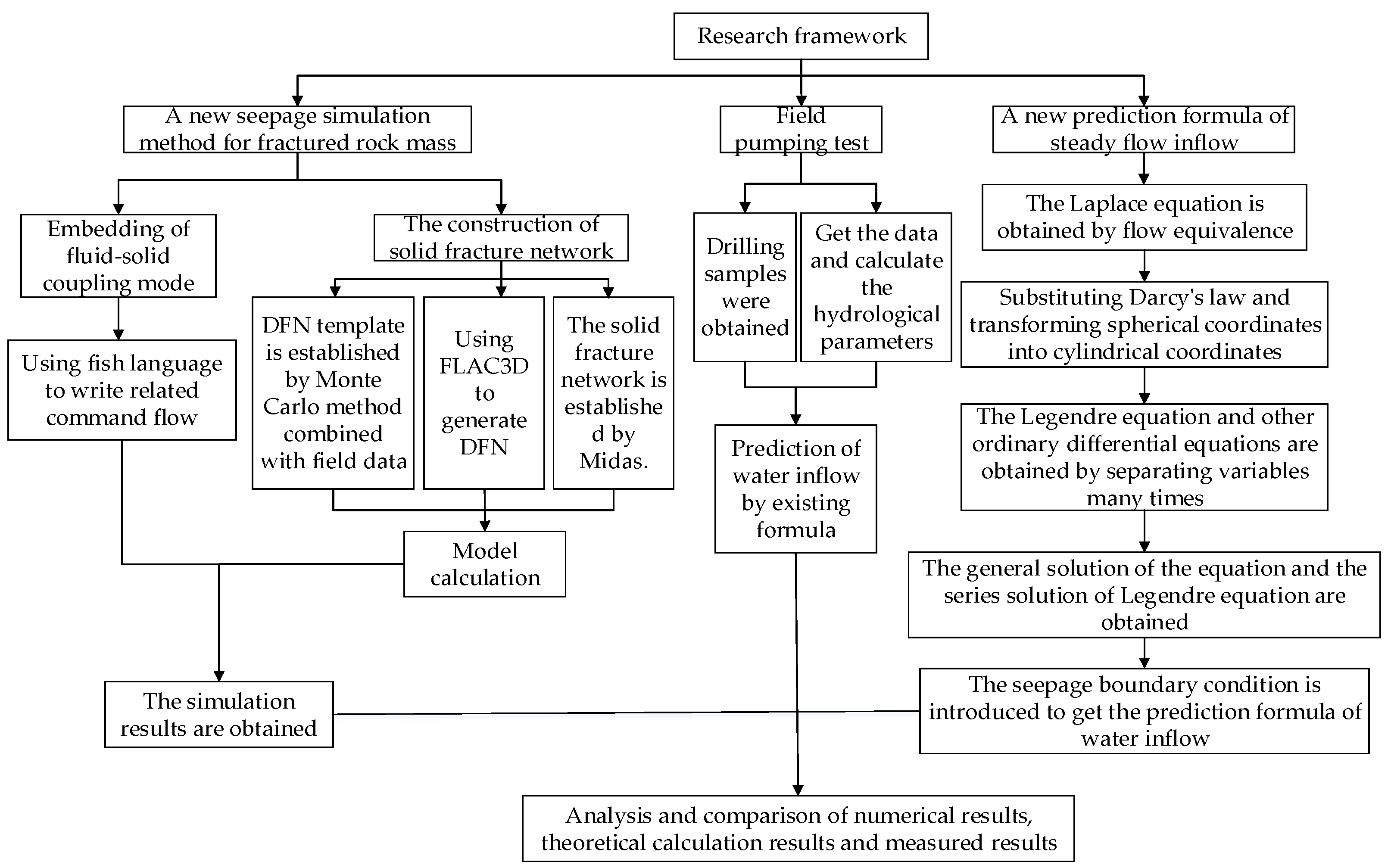
Figure 1. Research ideas.
Symmetry 13 00930 g001
Figure 2. Spot pictures.
Symmetry 13 00930 g002
Figure 3. Drainage equipment.
Symmetry 13 00930 g003
Figure 4. Modified urea formaldehyde resin slurry veins revealed by shaft excavation.
Symmetry 13 00930 g004
Figure 5. Discrete fracture network (DFN).
Symmetry 13 00930 g005
Figure 6. Comparison of two models.
Symmetry 13 00930 g006
Figure 7. Comparison of simulation results.
Symmetry 13 00930 g007aSymmetry 13 00930 g007b
Figure 8. Model map of different depth.
Symmetry 13 00930 g008
Figure 9. Initial geostress field at different depths.
Symmetry 13 00930 g009aSymmetry 13 00930 g009b
Figure 10. Some drilling samples.
Symmetry 13 00930 g010
Figure 11. Differential element.
Symmetry 13 00930 g011
Figure 12. Comparison of the calculation results between the formula in this paper and calculation formula of pressure bearing to no pressure.
Symmetry 13 00930 g012
Figure 13. Flow monitoring of working face in different excavation simulation stages.
Symmetry 13 00930 g013
Figure 14. Flow monitoring of shaft wall in different excavation simulation stages.
Symmetry 13 00930 g014
Figure 15. Water inflow monitoring in different excavation simulation stages.
Symmetry 13 00930 g015
Figure 16. Comparison chart of water inflow prediction.
Symmetry 13 00930 g016
Table 1. Statistics of geometric parameters of fracture group.
Fracture GroupCentral PointDip Angle
(°)
Dip Direction
(°)
Crack Trace Length(m)Density
(one/× 10−5 m2)
Uniform DistributionGaussiGaussiGaussi
Mean Value uVariance
σ
Mean Value uVariance
σ
Mean Value
u
Variance
σ
Mean Value uVariance
σ
NENENENENENENENENE
1--79.0011.03133.009.0036.0010.007
2--82.108.13161.0611.7133.9011.717
3--89.336.1033.619.9026.106.607
Table 2. Geological parameters of 280~400 m model.
Soil TypeElastic Modulus
E/× 104 MPa
Poisson’s Ratio
γ
Cohesion
C/MPa
Internal Friction Angle
φ
Tensile Strength/MPaDensity/g/cm3Height/m
Dark gray mixed granite (weakly weathered)0.530.305.0033.0013.002.110.00~−30.00
Light gray mixed granite (developed joints)0.660.267.0043.006.002.03−30.00~−60.00
Dark gray mixed granite (developed joints)0.730.333.0039.0010.002.33−60.00~−80.00
Light grey mixed granite (with relatively developed joints)0.960.2910.0036.0019.002.43−80.00~−120.00
Table 3. Geological parameters of 500 m~620 m model.
Soil TypeElastic Modulus
E/× 104 MPa
Poisson’s Ratio
γ
Cohesion
C/MPa
Internal Friction Angle
φ
Tensile Strength/MPaDensity/g/cm3Height/m
Dark gray mixed granite (weakly weathered)0.530.305.0033.0013.002.110.00~−30.00
Light gray mixed granite (developed joints)0.660.267.0043.006.002.03−30.00~−60.00
Dark gray mixed granite (developed joints)0.730.333.0039.0010.002.33−60.00~−80.00
Light grey mixed granite (with relatively developed joints)0.960.2910.0036.0019.002.43−80.00~−120.00
Table 4. Strength parameters of fracture group.
Fracture GroupNormal Stiffness
(GN/m)
Tangential Stiffness
(GN/m)
Internal Friction Angle
(°)
Cohesion
(MPa)
Shear Angle
(°)
Tensile Strength (MPa)Crack Width
(mm)
15050451--10
24040403--15
34545434--20
Table 5. Principal value of the seepage tensor of the fracture group.
Fracture GroupK1/× 10−9 cm/sK2/× 10−9 cm/sK3/× 10−9 cm/s
10.0001.701.70
20.0001.361.36
30.0010.570.57
Table 6. Hydrogeological parameters.
Name of AquiferAquifer Depth
(m)
Drawdown
(m)
Water Inflow
(L/s)
Unit Water Inflow
(L/s m)
Aquifer Thickness
(m)
Radius of Influence R (m)Permeability Coefficient K
(m/d)
Fourth aquifer3.03~694.7598.120.30110.00311.25555.920.321
Third aquifer9.45~498.9098.750.13990.00143.45216.350.048
Second aquifer9.33~343.7098.730.19630.00203.70249.770.064
First aquifer0.00~156.2571.361.05330.01481.75758.571.130
Table 7. Forecast value of project water inflow.
Aquifer Depth (m)Permeability Coefficient K (m/d)Static Water Level Height
H (m)
Water Level in Well
h (m)
Well Drops (m)Radius of Influence R (m)Shaft Waste Path
r (m)
Aquifer Thickness (m)Pressure to No Pressure
Q (m3/d)
3.03~694.750.321691.720691.723922.373.31.25246.77
9.45~498.900.048489.450489.451075.633.33.7094.26
9.33~343.700.064334.370334.37849.203.33.4583.26
0.00~156.251.130156.250156.251660.963.31.75310.90
Total///////735.19
Table 8. The prediction results of the formula in this paper are as follows.
Aquifer Depth (m)Permeability Coefficient
K (m/d)
Static Water Level Height
H (m)
Well Drops (m)Radius of Influence
R (m)
Shaft Waste Path
r (m)
Q
(m3/d)
3.03~694.750.321691.72691.721383.443.3871.21
9.45~498.900.048489.45489.45978.903.392.17
9.33~343.700.064334.37334.37668.743.383.93
0.00~156.251.130156.25156.25312.53.3691.89
Total/////1739.20
Publisher’s Note: MDPI stays neutral with regard to jurisdictional claims in published maps and institutional affiliations.