Article

Effect of Pulsatility on the Transport of Thrombin in an Idealized Cerebral Aneurysm Geometry

by
Struan Hume
1,†,
Jean-Marc Ilunga Tshimanga
2,†,
Patrick Geoghegan
3,
Arnaud G. Malan
1,
Wei Hua Ho
2,4,* and
Malebogo N. Ngoepe
1,5,*
1
Department of Mechanical Engineering, University of Cape Town, Rondebosch, Cape Town 7701, South Africa
2
Department of Mechanical Engineering, University of South Africa, Johannesburg 1709, South Africa
3
Department of Mechanical, Biomedical Engineering, Aston University, Birmingham B4 7ET, UK
4
School of Mechanical, Industrial and Aeronautical Engineering, University of the Witwatersrand, Johannesburg 2000, South Africa
5
Stellenbosch Institute for Advanced Study, Wallenberg Research Centre at Stellenbosch University, Stellenbosch 7600, South Africa
*
Authors to whom correspondence should be addressed.
Joint first authorship.
Symmetry 2022, 14(1), 133; https://doi.org/10.3390/sym14010133
Submission received: 14 September 2021 / Revised: 5 November 2021 / Accepted: 22 November 2021 / Published: 11 January 2022
(This article belongs to the Special Issue Biofluids in Medicine: Models, Computational Methods and Applications)

Abstract

:
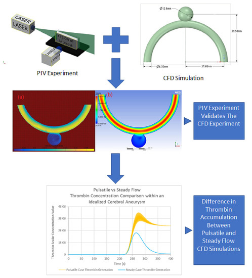
Computational models of cerebral aneurysm thrombosis are designed for use in research and clinical applications. A steady flow assumption is applied in many of these models. To explore the accuracy of this assumption a pulsatile-flow thrombin-transport computational fluid dynamics (CFD) model, which uses a symmetrical idealized aneurysm geometry, was developed. First, a steady-flow computational model was developed and validated using data from an in vitro experiment, based on particle image velocimetry (PIV). The experimental data revealed an asymmetric flow pattern in the aneurysm. The validated computational model was subsequently altered to incorporate pulsatility, by applying a data-derived flow function at the inlet boundary. For both the steady and pulsatile computational models, a scalar function simulating thrombin generation was applied at the aneurysm wall. To determine the influence of pulsatility on thrombin transport, the outputs of the steady model were compared to the outputs of the pulsatile model. The comparison revealed that in the pulsatile case, an average of 10.2% less thrombin accumulates within the aneurysm than the steady case for any given time, due to periodic losses of a significant amount of thrombin-concentrated blood from the aneurysm into the parent vessel’s bloodstream. These findings demonstrate that pulsatility may change clotting outcomes in cerebral aneurysms.

Graphical Abstract

1. Introduction

Cerebral aneurysms are localized expansions in cerebral arteries and are caused by structural inadequacies in the arterial wall. Thrombosis is closely associated with cerebral aneurysms and is defined as blood clotting within the circulatory system, under pathological conditions [1]. Aneurysm rupture is not a prerequisite for thrombosis [2,3,4]. In unruptured aneurysms, the role of thrombosis is ambiguous, with an increase in rupture risk for some cases and stabilization for others.
It is thought that there are similarities and differences between cerebral aneurysm thrombosis and standard physiological clotting [5]. The current view is that biochemical pathways function similarly in both processes, although these may be affected by administration of drugs [6]. The main differences are thought to arise from geometry-linked local hemodynamics and the behaviour of the vascular endothelium [7,8].
During physiological clot initiation, tissue factor is exposed at the injury site and creates a small amount of thrombin when it comes into contact with flowing blood [9]. Typically, the exposure of subendothelial tissue factor is a prerequisite for thrombin formation and therefore, clotting. Large portions of the vessel wall of cerebral aneurysms have an exposed subendothelial layer, creating the ideal conditions for clot initiation [8,10]. There is also evidence of blood-borne tissue factor, in pathological cases, which circulates with blood and seems to play an important role where there are abnormal stimuli [11,12,13]. This is notable due to the hemodynamic intricacy and variability of shear rates in cerebral aneurysms [14]. This hemodynamic environment is therefore an important part of cerebral aneurysm thrombus development.
Various computational tools have been developed to study cerebral aneurysms. Included in these are computational models focusing on cerebral aneurysm thrombosis, which can be classified as either thrombosis potential models or direct thrombosis models [5,15,16,17,18,19,20]. Thrombosis potential models identify flow conditions associated with thrombosis and forecast clotting outcomes on that basis. Direct thrombosis models couple physiological models of platelet and/or biochemical protein activity with local haemodynamics. Both categories recognize the importance of flow.
Computational fluid dynamics (CFD) is the main tool for incorporating flow in computational blood clotting studies and a steady-flow assumption is widely used, largely due to the relatively low computational expense. Pulsatility appears to have an effect on the clotting process, however. Exploration of pulsatility in a microfluidics experiment demonstrated that tissue factor expression in human umbilical vein endothelial cells was higher under pulsatile flow than static flow [20]. Human platelets have been shown to respond differently to shear stress induced by pulsatile flow, affecting thrombin generation and platelet adhesion [21]. A 2D CFD study has explored pulsatile flow by applying varying pulsatility and velocity to a stepwall transition with varying height [22]. Another CFD study of flow through realistic cerebral aneurysm geometries demonstrated that pulsatility had a significant effect on wall shear stress in aneurysms and was therefore an important factor to consider when designing stents [23].
While much of the focus has been placed on platelet response to pulsatile flow, few studies have focused on the impact on protein transport in cerebral aneurysms. Given the evidence relating to platelets and other blood cells, it is conceivable that for cerebral aneurysms, periodically changing flow rates could alter the behaviour and transport of blood clotting proteins such as thrombin, the main contributor to clot formation [24]. Owing to the frequent occurrence of pulsatile flow patterns in vivo, there is rationale for the inclusion of pulsatility in computational models of thrombosis in cerebral aneurysms. The aim of this study, therefore, is to determine if the application of pulsatile flow within a cerebral aneurysm geometry results in appreciable differences in thrombin transport patterns.

2. Materials and Methods

The methods described in this section give details of the numerical simulations and experimental particle image velocimetry study (PIV), in an idealized symmetrical geometry. The experimental study employs steady-state conditions, and the results are used to validate the steady flow numerical model, which applies the lower order PIV inlet velocity for an initial comparison to the PIV measurements. The numerical model is then used to explore the effects of steady flow and pulsatility on thrombin retention and distribution within the aneurysm.

2.1. Idealised Geometry

A symmetrical idealized geometry, based on that developed in the work of Mulder et al., is employed [25]. The symmetrical idealized cerebral aneurysm geometry was recreated using ANSYS DesignModeler and ANSYS Spaceclaim (ANSYS, Lebanon, PA, USA). It consists of a cylindrical artery and a spherical aneurysmal sac, illustrated in Figure 1. This geometry was used for the experimental setup and for numerical simulations.

2.2. Experimental Study

2.2.1. Symmetrical Idealised Phantom

The symmetrical idealised geometry illustrated in Figure 1 was 3D printed on a desktop Stereolithography printer (Form2) from Formlabs, with FLGPCL clear resin. This geometry was then post-processed to improve clarity. Details of the entire process are presented in [25].

2.2.2. Working Fluid

Ammonium thiocyanate (NH4SCN) was prepared as an aqueous solution, undergoing an endothermic reaction during dissolution. The motivation behind the use of ammonium thiocyanate as a working fluid was its refractive index (RI) range (1.33–1.5 [26]), which enabled RI matching with the printed phantom (RI = 1.507 ± 0.003 [25]). RI matching minimizes the effect of optical distortion on the PIV results and analysis. Additional information about ammonium thiocyanate solutions and their RIs can be found in the work of Borrero-Echeverry and Morrison [27], while further details about the RI matching process for this particular study can be found in Ho et al. [25].

2.2.3. Flow Circuit

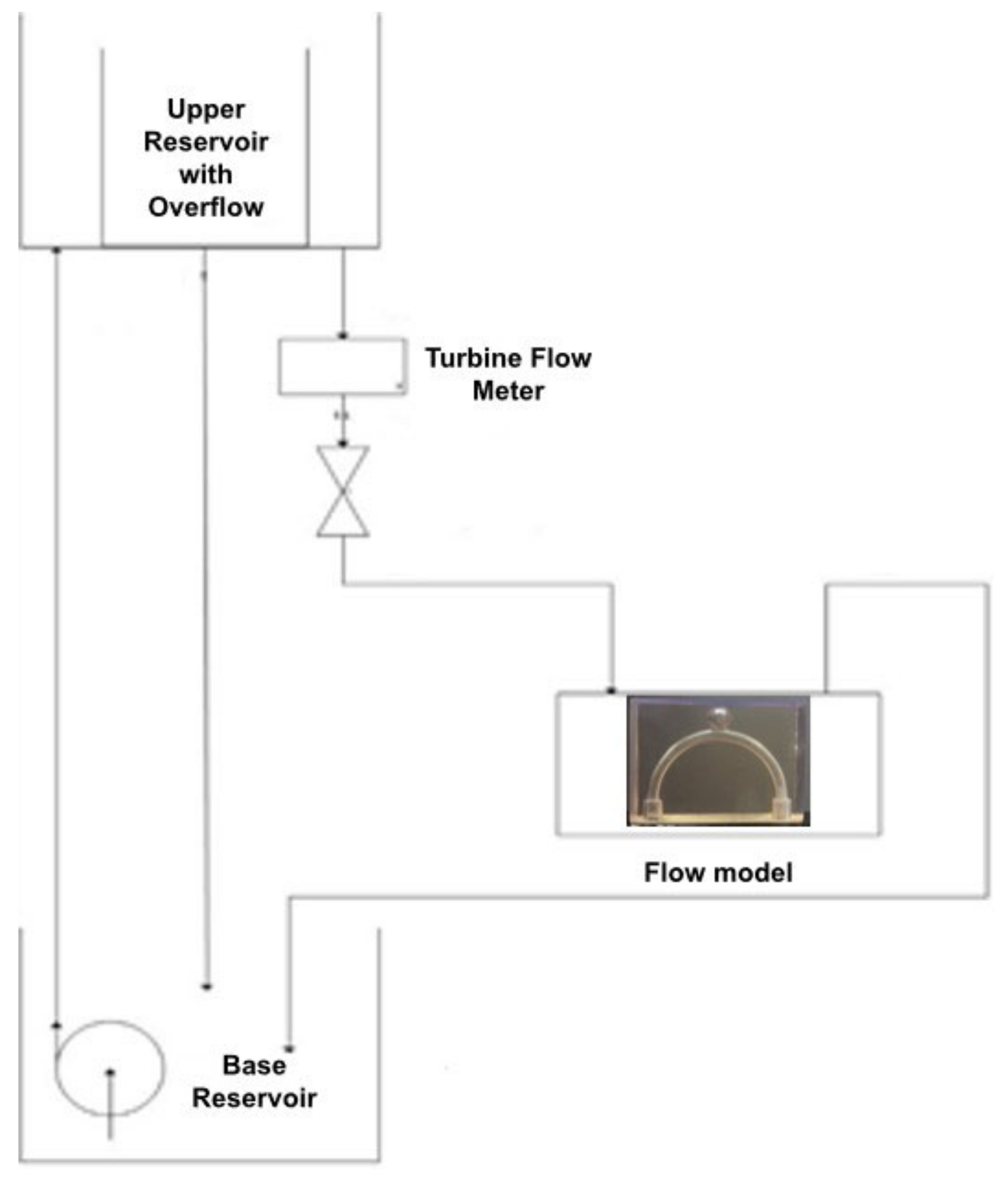
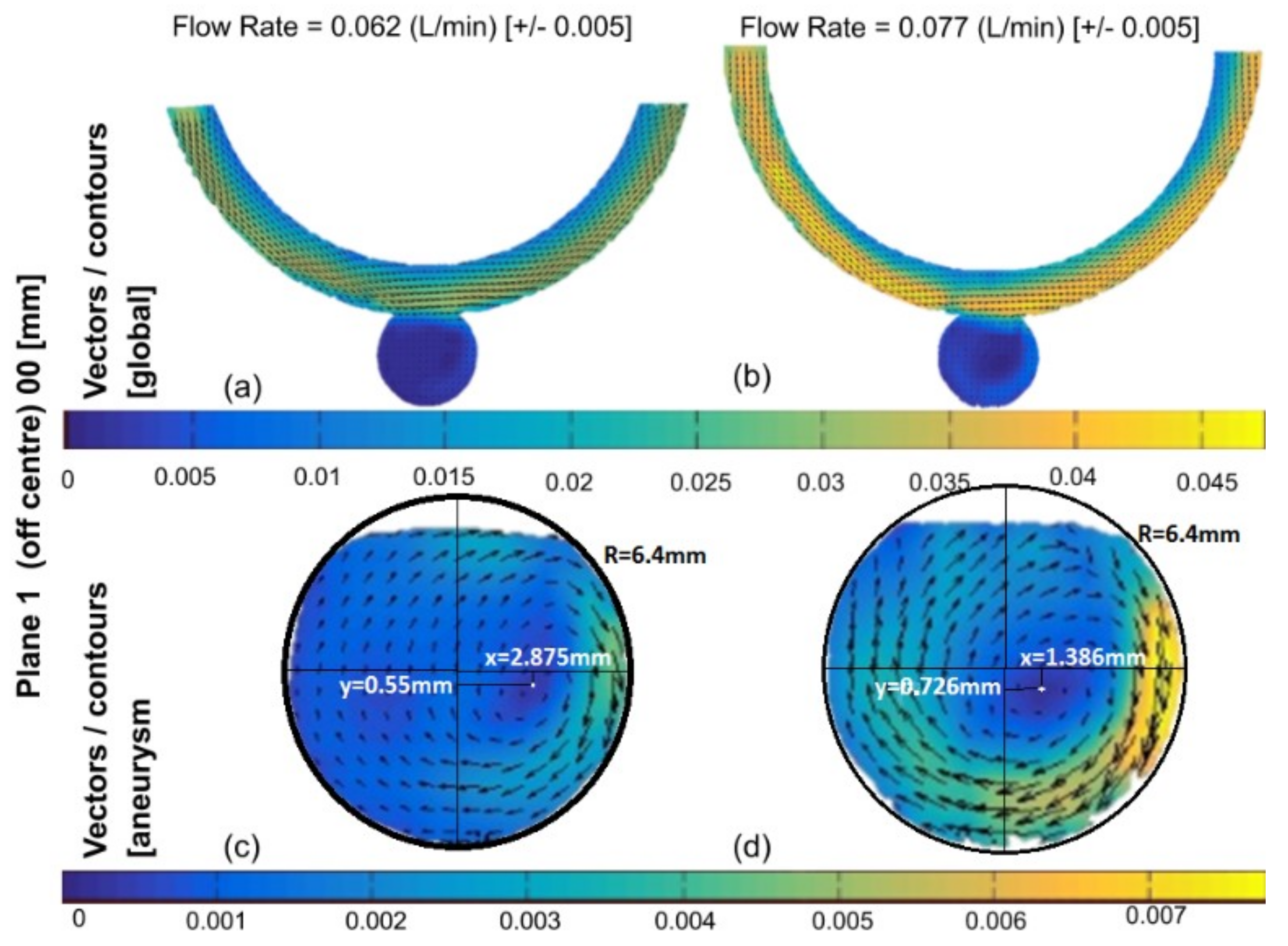
A closed-loop steady flow circuit was designed and fabricated to validate the computational model (Figure 2). It consists of a base reservoir, an upper reservoir with an overflow weir, a screw valve and a turbine flow meter to control and measure the flow, respectively. The turbine flow meter is a FT-210 ¼” from GEMS sensor (Gems Sensors and Control, Plainville, CT, USA) and the readout is obtained from a PD6300 ProVu Pulse Input Flow Rate/Totalizer from Precision Digital (Precision Digital, Hopkinton, MA, USA). A small submersible filtration pump from Sunsun (Sunsun Group Co., Zhoushan, China) is used to pump the working fluid from the base reservoir to the upper reservoir, which then feeds the main flow phantom. The flow is then returned to the base reservoir. The upper reservoir weir maintains a constant pressure head, which enforces a constant flow rate through the flow phantom. Two flow rates were used in the experiment (0.062 L/min and 0.077 L/min). These correspond to Reynolds numbers of 100 and 150, respectively, which fall within the range of in vivo blood flow in cerebral blood vessels, adjusted for dynamic similarity [28,29].

2.2.4. PIV Setup

The detailed flow field within the flow model was measured using planar PIV, consisting of a single 2 MP PCO Pixelfly PIV camera and a Firefly laser from Oxford Lasers (Oxford Lasers Ltd., Didcot, UK). The seeding particles used for the experiment were neutrally buoyant 20 µm hollow glass spheres from Dantec Dynamics (Dantec Dynamics, Skovlunde, Denmark). Images were taken at the centre plane (0 mm), at 2 mm offset and at 4 mm offset, totaling three planes. The time between two images within an image pair needs to be sufficiently small to capture expected displacement within the limits of cross-correlation algorithms. A general rule is to set the timing between image pairs (∆t) to correspond to a particle displacement of approximately one quarter or one third of the size of the interrogation area [30]. The maximum velocity in this study was 0.033 m/s, hence a ∆t of 16.6 ms was applied.

2.2.5. Processing of PIV Measurements

Background subtraction on the raw captured images was performed using the code proposed by Mendez et. al., based on Proper Orthogonal Decomposition (POD) decomposition of the raw images [31]. Processing of results was performed using PIVlab 1.4.2 [32].

2.3. Numerical Simulations

Meshing was conducted in ANSYS meshing, while simulations were carried out in ANSYS Fluent and post-processing in ANSYS CFD-Post (ANSYS, Lebanon, PA, USA).

2.3.1. Navier–Stokes Equations

The flow of the fluid field, illustrated in Figure 1, is governed by the Navier-Stokes equations,
· U = 0
ρ U t + ρ U · U + P = μ 2 U ,
where U is a sample velocity vector, ρ is the fluid density, μ is the dynamic fluid viscosity, t is time and P is pressure.
Human blood is a non-Newtonian fluid. Consequently, several elements cause its fluid properties to vary. Blood is assumed to be Newtonian for this study, since flow is laminar, and the vessel under consideration is sufficiently large, for the non-Newtonian characteristics of blood to be considered negligible [33]. Blood is therefore modelled with a density, ρ , of 1000 kg/m3 and viscosity, μ, of 0.004 kg/m.s, and is considered incompressible.

2.3.2. Boundary Conditions

For the numerical simulations, both steady and pulsatile boundary conditions were investigated. Velocity and pressure waveforms, illustrated in Figure 3, were applied as the inlet and outlet boundary conditions, respectively.
Ferns et al. provide in vivo cerebral artery pressure and velocity flow data measured proximally upstream from an aneurysm in the internal carotid artery at the cervical level [34]. For the pulsatile boundary conditions, a velocity Fourier transform function, fitted to this velocity data and illustrated in Figure 3, was uniformly implemented, normal to the inlet boundary. This plug flow developed as it travelled through the parent artery and resembled Poiseuille flow upstream from the aneurysm. A similarly derived pressure Fourier transform was implemented at the outlet and is also illustrated in Figure 3. The equations for the pressure and velocity Fourier transforms are given by
P = 26.298 sin 2 π 0.9 t + 24.082 13.633 × sin 2 π 1.8 t + 12.73 + 5.891 × sin 2 π 2.7 t 1.789 + 74.982
U t = 14.598 × sin 2 π 0.9 t + 15.031 7.46 × sin 2 π 1.8 t + 0.805 + 2.509 × sin 2 π 2.7 t 0.782 + 20.804
The steady-flow simulation applied the average of these transforms at the respective boundary conditions, with a pressure outlet value of 83 mmHg and a velocity inlet value of 0.23 m/s, as illustrated in Figure 3.
At the aneurysm and parent vessel artery walls, illustrated in Figure 1, a no-slip wall boundary condition was applied. Thrombin, the key protein involved in clotting, was released at the aneurysm wall.

2.3.3. Transport Equation for the Description of Thrombin

The general scalar transport equation is converted into an algebraic equation that is numerically solvable using a control-volume-based technique. The general scalar transport equation is given by
ρ ϕ t + · ρ ϕ v = · Γ ϕ ϕ + S ϕ
where ϕ is the scalar quantity of interest, v is the velocity vector, A is the area, Γ ϕ is the diffusion coefficient of ϕ , ϕ is the gradient of ϕ , S ϕ is the source of ϕ per unit volume.
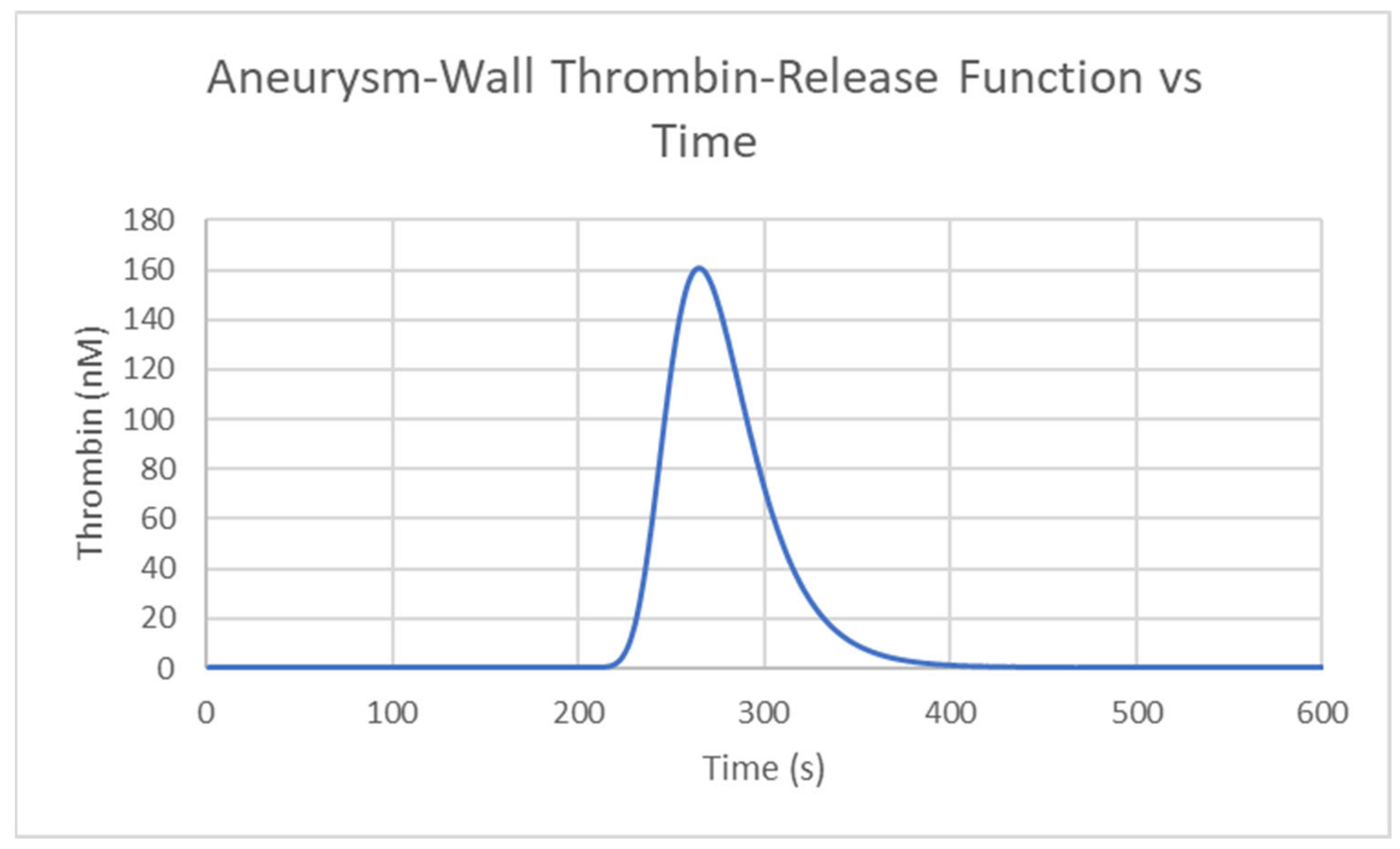
A variable thrombin release model derived from a thrombin generation curve fitting function was applied at the entire wall of the aneurysm shown in Figure 1, to determine how thrombin concentrates and distributes within the aneurysm reacting to the main flow stream in the artery [35]. While the generation of thrombin results from a complex set of equations, the interest, in this particular study, was to observe the effect of pulsatility on the transport of thrombin. As a result, thrombin was specified as a boundary condition. The variable thrombin release equation is given by,
T H t = 2.73 P E A K 2 / E T P × e x p 2.73 t T T P × e x p P E A K / E T P × e x p 2.73 t T T P
where T H is thrombin concentration, P E A K is the peak thrombin generation value, E T P is the area under the thrombin curve and T T P is the time to peak. The values of PEAK, ETP, and TTP are 160 nM, 800 nM.min and 5 min, respectively, and result in the curve shown in Figure 4.
A user-defined scalar (UDS) was used to model thrombin concentration in ANSYS fluent. The variable thrombin release model interacted with the UDS by adjusting the diffusion value of the UDS nearby surfaces on which the model operated. The interaction of the variable thrombin release model at the aneurysm wall with UDS diffusion is given by
T H t = Γ k ϕ x i · n
where, ϕ is the unitless scalar representing thrombin, Γ k is the diffusion coefficient, and n is the vector normal to the surface of thrombin release. The diffusion coefficient Γ k is set as the value for thrombin of 6.68 × 10⁻⁷ kg/m.s.

2.3.4. Solver Settings

An implicit pressure-based solver using an algebraic multigrid was applied, wherein a control-volume-based technique was used to convert the general scalar transport equation to a numerically solvable algebraic equation. The PISO scheme was used for pressure-velocity coupling. A least-squared cell-based gradient was applied so that the cell gradient can be resolved with the Gram–Schmidt process, and the PRESTO! scheme was used for pressure. Second-order upwind momentum, scalar, and time advancement schemes were applied.

2.3.5. PIV Comparison Simulation

A simplified 2D approximation of the geometry, shown in Figure 1, was used for the PIV comparison simulation [36]. The outlet gauge pressure was set as 83 mmHg, while the inlet velocity was derived from the PIV velocity values of the coordinates at location 1, shown in Figure 5. The inlet velocity profile is shown in Figure 6, and is given by
V t = 0.0003 x 6 + 0.0041 x 5 + 0.0032 x 4 0.0373 x 3 0.2342 x 2 0.21682 x + 2.9963

3. Results

This section begins with a presentation of the steady-state experimental results obtained from PIV measurements. This is followed by grid independence results of the numerical model. The steady-state experimental results are then used to validate the steady state numerical simulations, as detailed in the third section. In the final section, a comparison of steady and pulsatile numerical simulations is presented.

3.1. Experimental Results

At the centre plane (Figure 7), two observations are apparent. First, higher velocities are observed in the parent vessel on the side of the aneurysm. This can be attributed to the centrifugal effect, even though the flow may be relatively low. Of equal importance is the centre of rotation within the aneurysm, which is asymmetrically positioned towards the right wall (coordinates given in Figure 7c,d). These two observations are consistent for both flow rates but are different, relative to each other. The first observation is more pronounced at the higher flow rate but the displacement of the centre of rotation is reduced. The displacement was (+2.875, −0.55) for the lower flow rate and (+1.386, −0.726) at the higher flow rate. The velocities near the wall of the aneurysm are also different as a result of the inflow angle. For the low flow rate, the highest velocity inside the aneurysm was 0.005 m/s, located at approximately (+6.4, 0), which is a location at the wall. For the higher flow rate, the location remained the same (+6.4, 0) but the velocity magnitude increased to 0.0075 m/s.
In the other planes, the centre of the vortex does not shift its location significantly with changing flow rate but remains at (2.00, 0.) on the second plane, shown in Figure 8. However, the centre of vortex’s axis shifts significantly from one plane to the other and moves upwards as the plane gets closer to the wall, as shown in Figure 8. The maximum velocity in this region is 0.002 m/s while the minimum velocity is close to 0 m/s.

3.2. Grid Independence for Numerical Results

Grid independence was tested using the steady-flow simulation, wherein a comparison was made between probe values of meshes of decreasing complexity to values of the baseline mesh described in Table 1. Three probes are applied: a surface probe at the inlet and, a z-axis line probe through the centre of the aneurysm, and an x-axis probe through the centre of the outlet. The area-weighted average of pressure and velocity is measured across these probes at each timestep, for 1000 timesteps. In each case, flow is fully developed around 1.5 s. Illustrated in Table 1, velocity changes slightly with increasingly coarser meshes, and pressure changes very little.
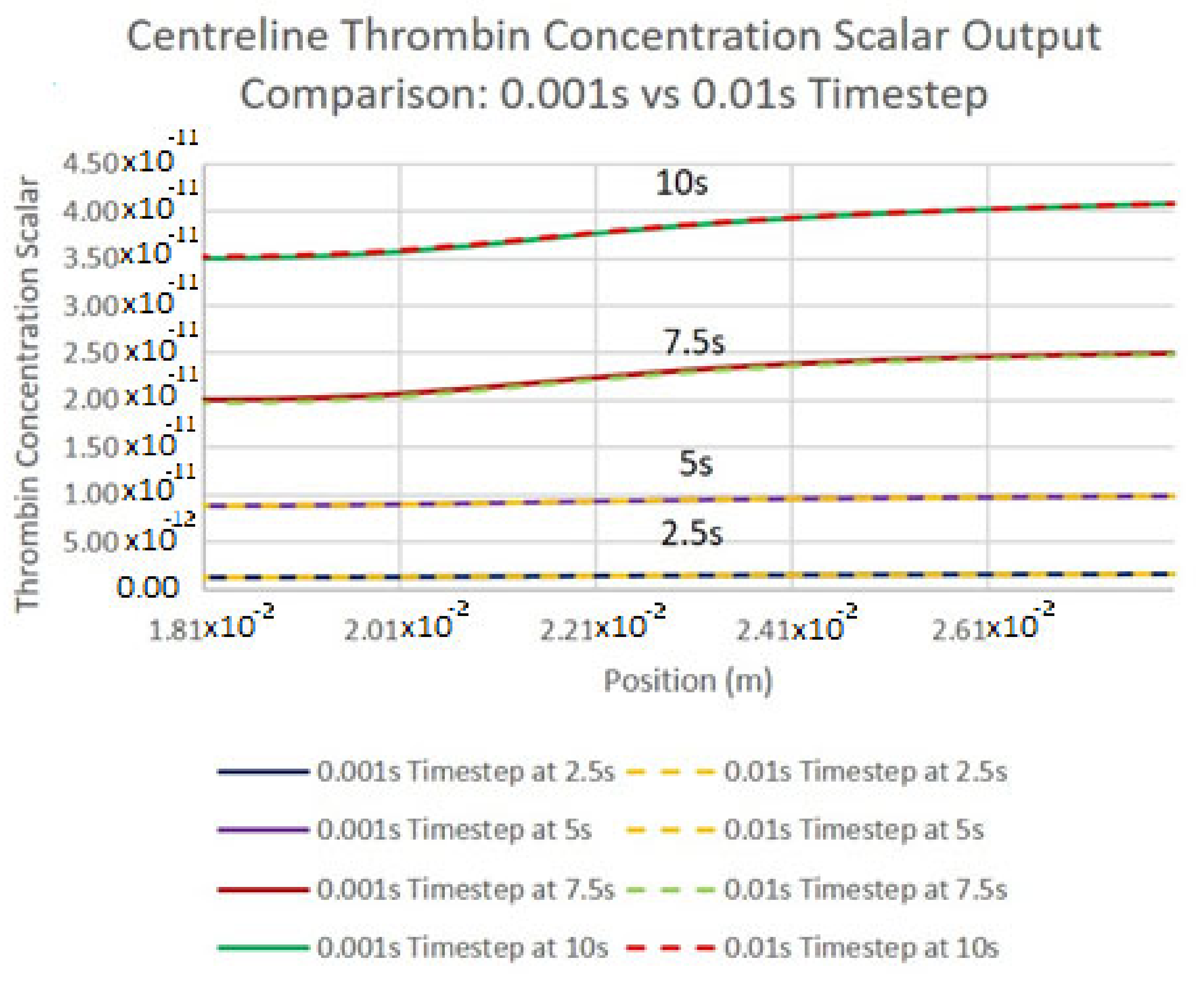
To ensure that each timestep sufficiently captured enough detail, an initial timestep was selected such that the largest cell-convective Courant number within the aneurysm zone was no greater than 1. This was achieved by dividing the minimum aneurysm zone element size by the average velocity at the inlet, resulting in a timestep of roughly 0.001 s. An analysis was then made between the thrombin concentration output along the centreline probe at four discrete times, shown in Figure 9. The application of this small timestep resulted in lengthy simulation times, hence the process was repeated with a larger timestep of 0.01 s. A comparison was then made between the two sets of results, and it was determined that the remaining simulations would be conducted with a 0.01 s timestep.

3.3. Comparison of Experimental and Numerical Results

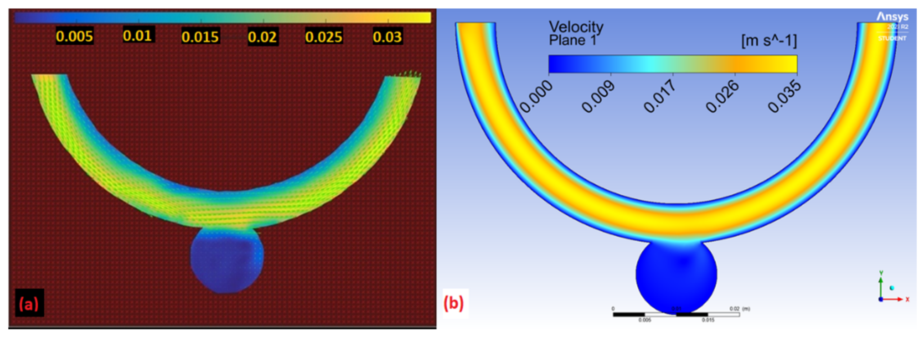
Deviations between the computational and experimental contours, illustrated in Figure 10, were most prominent at the inner walls. Here, velocity is lower for the PIV measurement when compared with the simulation. Velocity profiles for the numerical results demonstrate a near-even flow distribution within the parent artery zone, where maximum flow velocity is located close to the vessel centreline. The experimental results, on the other hand, depict high flow velocity near the outer wall of the artery zone and low flow towards the inner wall of the vessel.
The numerical average flow velocities at each numbered location illustrated in Figure 5 are measured against the experimental flow velocity averages at the same locations, shown in Table 2. Deviation from the experimental results is relatively low at the horizontally oriented locations within the artery, other than position 10, and relatively high at the vertically oriented locations, apart from location 7. Within the aneurysmal sac, deviation is relatively low at location 5, and relatively high at location 6.

3.4. Comparison of Pulsatile and Steady State Numerical Results

For both the steady and pulsatile cases, thrombin generation begins at 121 s. As shown in Figure 11, thrombin within the aneurysm peaks at 270 s at a value of 6.8 × 10³ nM and 6.1 × 10³ nM for the steady and pulsatile case respectively. On average there is 10.2% reduction in thrombin concentrated in the aneurysm in the pulsatile case than the steady case at any given time when thrombin is present.
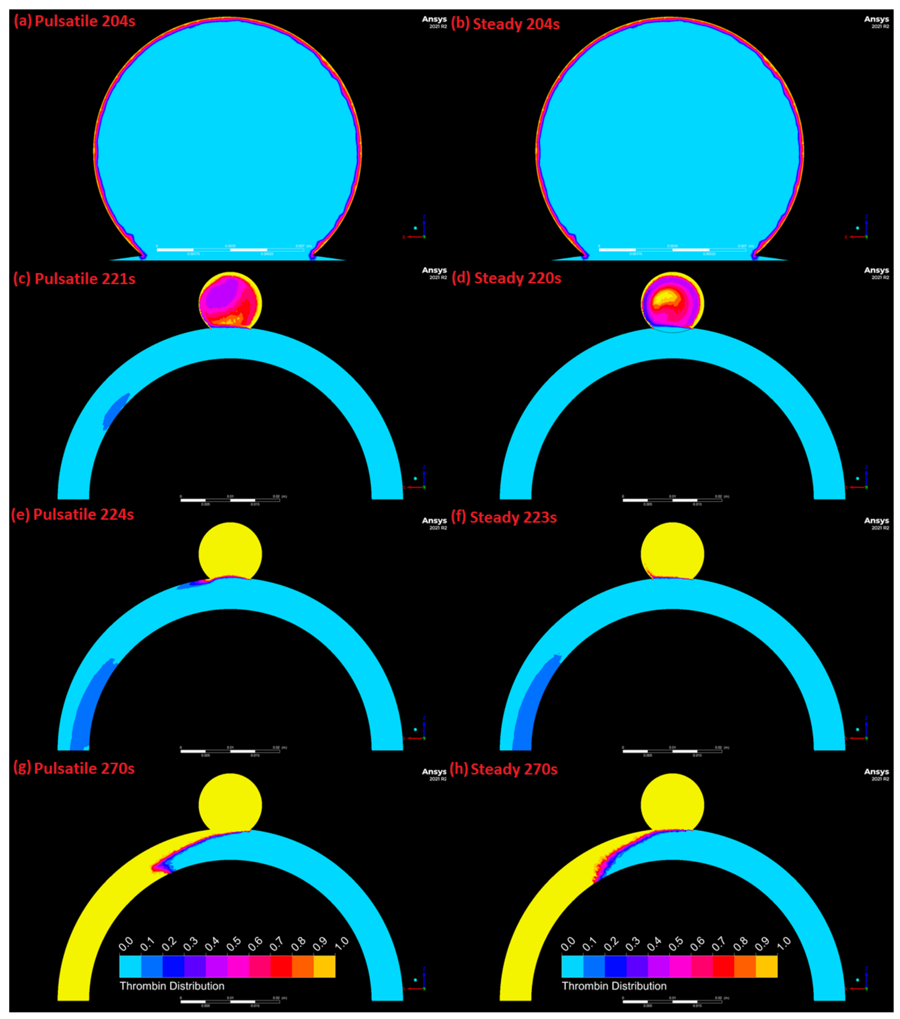
The thrombin concentration clotting threshold (approximately 1 nM) is met at computational cells along the aneurysm wall at 204 s (Figure 12), and this threshold ceases to be met by any computational cells past 563 s. For the steady case, the thrombin concentration threshold for clotting is met by cells in the center of the aneurysm at 220 s, and nearly all cells within the aneurysm at 223 s (Figure 12). For the pulsatile case, the thrombin concentration threshold for clotting is met by cells in the center of the aneurysm at 221 s, and nearly all cells within the aneurysm at 224 s (Figure 12). A large portion of the artery also eventually has a high enough concentration of thrombin for clotting as shown in Figure 12g,h. The shape of this region is different between the pulsatile and steady case as shown in Figure 12g,h.
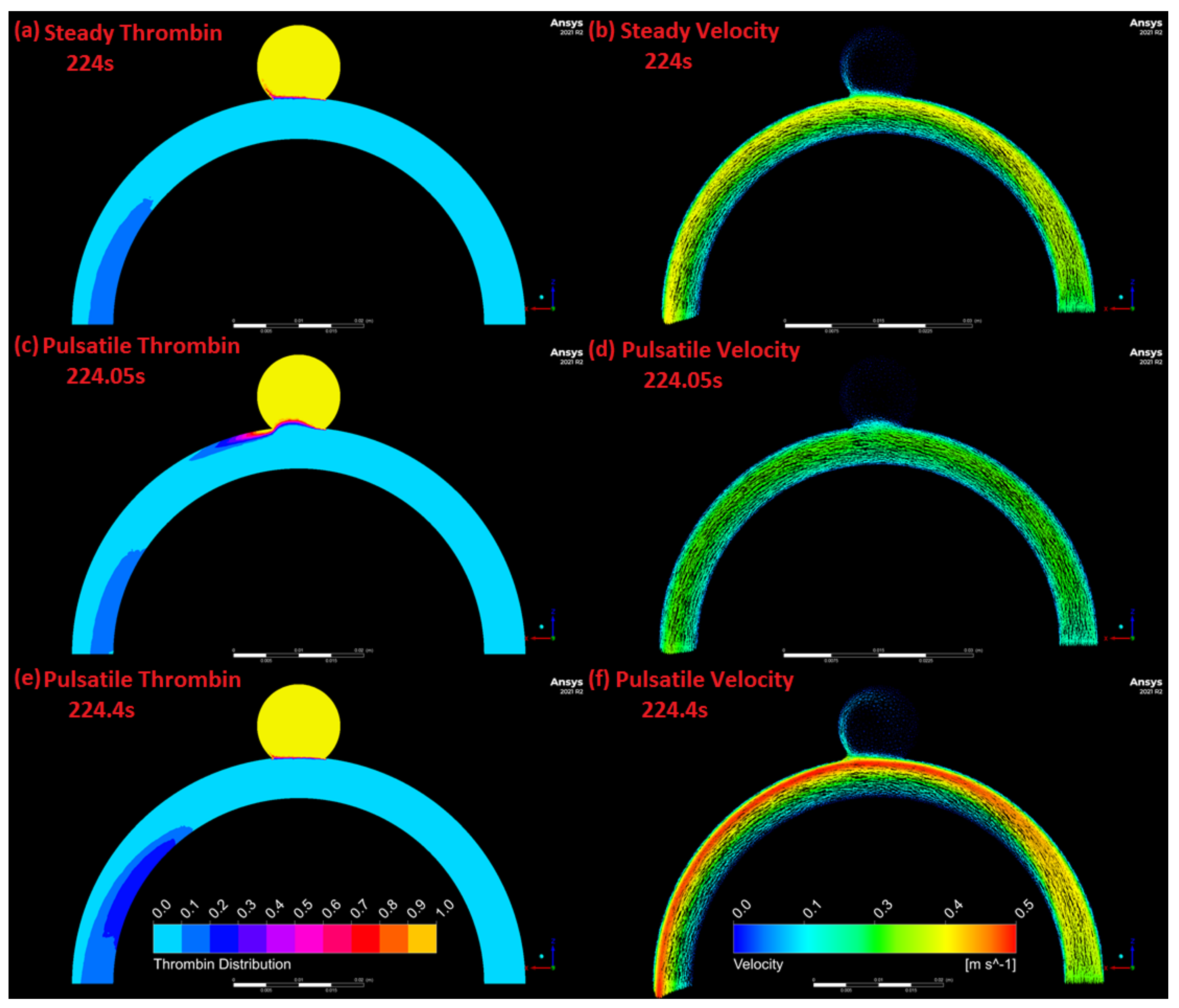
As shown in Figure 13b,d,f, flow velocity is highest in all cases towards the side of the wall of the parent artery tending towards the positive z-axis (upward). As shown in Figure 13b, for the steady case a segment of this high-velocity flow stream diverts into the aneurysm and circulates along the side of the aneurysm wall. Similar behavior can be seen in the pulsatile case shown in Figure 13f, which is representative of the relative distribution of flow throughout the majority of the pulse. The similarities in flow behavior shown in Figure 13b,f correlates with the similarities in steady (Figure 13a) and pulsatile (Figure 13e) case thrombin distribution, which also holds for the majority of a pulse. The flow behavior noted in Figure 13a,e is less prevalent in Figure 13d, which is representative of the pulsatile case flow distribution for roughly 0.15 s after the lower velocity peak of the pulsatile inlet function shown in Figure 3, where velocity increases sharply towards the upper velocity peak. The flow distribution presented in Figure 13d is correlated with a large periodic loss of thrombin shown in Figure 13c. Additionally of note is thrombin becoming concentrated within the artery towards the outlet as demonstrated in Figure 13a,c,e.
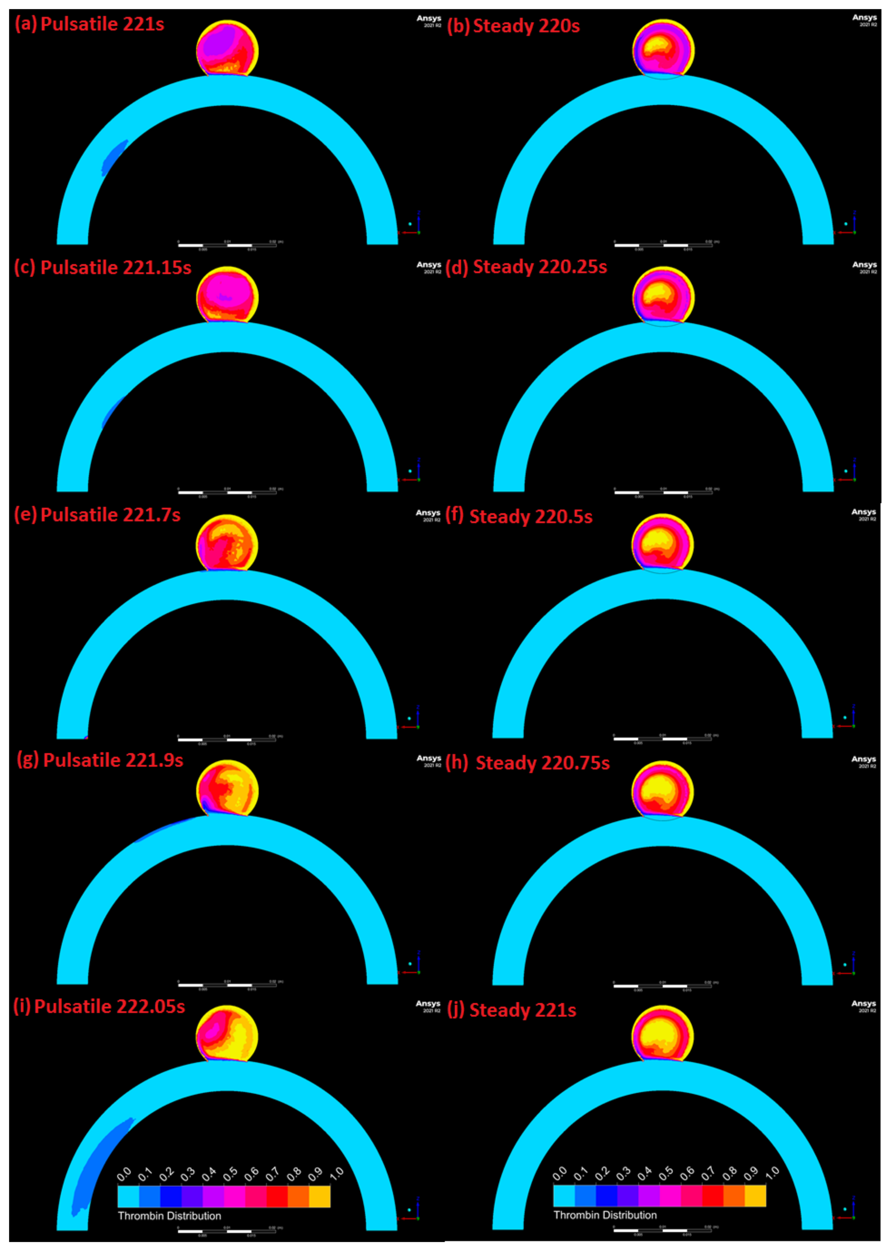
Figure 14 demonstrates differences in the way thrombin concentrates in the aneurysm between the steady and pulsatile case. As shown in Figure 14b,d,f,h,j, in the steady case thrombin appears to concentrate roughly uniformly and roughly offset from the center of the aneurysm. The pulsatile case by comparison demonstrates that thrombin initially concentrates at the bottom of the aneurysm (Figure 14a) just after the upper velocity peak of the pulsatile velocity inlet function (Figure 3), and circulates clockwise from the direction of flow in the artery around the center of the aneurysm to the top of the aneurysm (Figure 14c,e) as the lower velocity peak of the pulsatile velocity inlet function is approached. The thrombin continues to revolve around the center of the aneurysm clockwise from the direction of flow in the artery as shown in Figure 14g and eventually reaches the bottom of the aneurysm again by the upper velocity peak as shown in Figure 14i.

4. Discussion

A numerical model was used to determine whether the application of pulsatility in a cerebral aneurysm model results in significantly altered thrombin transport patterns, when compared to the commonly used steady-state assumption. PIV is one of the tools of choice for validating CFD simulations of blood flow in arteries. Planar PIV measurements were conducted under steady state conditions. A symmetrical idealized geometry of a cerebral aneurysm was used for experimental and numerical studies. Results from the PIV studies were used to validate the computational model of thrombin transport in cerebral aneurysms, under steady state conditions. Both experimental and numerical studies revealed important characteristics of blood flow in cerebral aneurysms. Blood flow inside the aneurysm was much slower than in the parent artery and an asymmetrically positioned vortex was present inside the aneurysm sac. The numerical solution seems to yield slightly higher velocity values and the location of the highest velocity flow within the parent artery is situated much further away from the wall, when compared to experimental results. The numerical model was then used to explore the effects of pulsatility.
The thrombin concentration scalar value (order of magnitude 1 nM) required to activate clotting is reached at approximately the same time for each case [24]. Once this threshold value is attained, approximately 10.2% less thrombin is retained in the aneurysm at any given time under the pulsatile flow condition. This appears to be caused by periodic high rates of flow into the aneurysm sac which are correlated with sharply increasing flowrates after the lowest velocity peak of the pulsatile velocity inlet function shown in Figure 3. Velocity magnitude changes periodically in the pulsatile flow simulation, resulting in variable flow patterns. This uneven and changing flow distribution may hinder the recirculation of thrombin within the aneurysm, contributing to loss into the flow-stream of the parent artery.
Figure 13c,d illustrate that when flow within the aneurysm begins to stagnate and is then suddenly exposed to a rapidly increasing rate of flow from the parent artery, a significant amount of thrombin is pushed from the aneurysm out into the parent artery. Conversely, when there is sufficient flow for recirculation within the aneurysm, such as in Figure 13a,b,e,f, there is steady but less dramatic loss of thrombin into the parent artery. This indicates that steady and higher flowrates will create more ideal recirculation within the aneurysm for thrombin retention, and that periodically low flowrates can create irregular recirculation which may hinder thrombin retention within the aneurysm.
It is also clear that based upon the comparison illustrated in Figure 14 between thrombin concentration in the steady and pulsatile cases, that there is a difference in how a clot may form given that all the other conditions for clotting are met. Clotting will initiate at the walls in both cases given Figure 12a,b. However, when sufficient thrombin is circulating in the center of the aneurysm for clotting to occur in free flow, in the steady case the clot will form at roughly the center of the aneurysm and grow outwards in all directions, where in the pulsatile case a clot will form offset from the center and spin around the aneurysm as it forms.
Compared to the presented computational model, a similar thrombin distribution is observed in Ouared et al.’s intracranial aneurysm thrombosis model employing a lattice Boltzmann numerical algorithm, which applies a pulsatile pressure outlet to a comparable idealised large aneurysm [37]. Applying Lieber et al.’s findings, the maximum shear exerted onto the aneurysmal sac must meet the wall shear threshold for clotting to occur, indicating that conditions for exceeding the wall shear threshold for clotting are more ideal in the steady case than the pulsatile case [38]. Considering these results in tandem with those of Corbett et al., and presuming that flow behaviour past the aneurysm sac and a step-wall transition are roughly analogous, the pulsatile case has both less stagnation and higher maximum wall shear than the steady case, in the aneurysm [22]. Based on the findings of Moriguchi et al., tissue factor expression within the aneurysmal sac would be higher in the pulsatile case [20]. Correlating these findings with the observations of Steadman et al., the increased presence of tissue factor paired with the high wall-shear at the aneurysm neck could potentially increase thrombin generation in the pulsatile case in this area [21]. It is unclear how much of this extra thrombin would be retained, though it is plausible that it could be partially swept into the aneurysm throughout the majority of a pulse and mitigate the thrombin losses into the blood stream when there is low flow within the aneurysm as demonstrated in Figure 13c,d. Overall, application of previous literature suggests that steady flow through the presented geometry will create conditions where the flow requirements for clotting to occur within the aneurysmal sac are more easily achieved, and result in greater retention of clotting components. Pulsatile flow by comparison may compound thrombin within the aneurysmal sac via increased tissue factor expression that causes further thrombin generation, but irregular circulation will cause a larger portion of this thrombin to be periodically lost. With the inclusion of a stent, the clotting outcomes recorded by Gester et al. provide insight to what may occur in the presented pulsatile computational model inclusive of a direct thrombosis model [39].

5. Conclusions

Based on our study, pulsatile flow appears to have an impact on protein transport in cerebral aneurysms, resulting in less retention of thrombin in the aneurysmal sac and periodic outflow into the parent vessel’s stream. The main limitation of this study is that only thrombin transport is considered, rather than the full clotting process. While this limits our ability to consider the effects of pulsatility in their entirety, thrombin is key to the clotting process and alteration in its accumulation, as demonstrated in this study, is likely to lead to differences in the clotting pattern overall. Focusing on one key protein has also made it possible to further tease out the influence of flow and boundary conditions, without having the confounding effects of an otherwise very complicated biochemical system.

Author Contributions

Conceptualization, M.N.N.; Methodology, S.H., J.-M.I.T., M.N.N., W.H.H., P.G. and A.G.M.; Formal analysis, S.H., M.N.N., J.-M.I.T., W.H.H., P.G.; Data curation, S.H. and J.-M.I.T.; Writing—original draft preparation, M.N.N., J.-M.I.T. and S.H.; Witing—review and editing, W.H.H., P.G. and A.G.M.; Visualization, S.H. and J.-M.I.T.; Supervision, M.N.N., W.H.H. and P.G.; Funding acquisition, A.G.M., M.N.N. and W.H.H. All authors have read and agreed to the published version of the manuscript.

Funding

National Research Foundation, South Africa for funding the work through Thuthuka and NRF-FRF Sabbatical grants held by MNN, NRF KIC grant (KIC171023270560), and African Laser Centre research grant (LHIN500 task ALC-R017) held by W.H.H. This work is also based on research supported by the National Research Foundation of South Africa (Grant Number: 89916) held by AGM. The opinions, findings and conclusions or recommendations expressed are that of the authors alone, and the NRF accepts no liability whatsoever in this regard.

Data Availability Statement

Datasets related to this article can be found at 10.25375/uct.16616227, hosted at ZivaHub.

Conflicts of Interest

The authors declare no conflict of interest.

References

  1. Lawton, M.T.; Quiones-Hinojosa, A.; Chang, E.F.; Yu, T. Thrombotic Intracranial Aneurysms: Classification Scheme and Management Strategies in 68 Patients. Neurosurgery 2005, 56, 441–454. [Google Scholar] [CrossRef]
  2. Eller, T.W. MRI demonstration of clot in a small unruptured aneurysm causing stroke. Case report. J. Neurosurg. 1986, 65, 411–412. [Google Scholar] [CrossRef] [PubMed]
  3. Ishikawa, T.; Nakayama, N.; Yoshimoto, T.; Aoki, T.; Terasaka, S.; Nomura, M.; Takahashi, A.; Kuroda, S.; Iwasaki, Y. How does spontaneous hemostasis occur in ruptured cerebral aneurysms? Preliminary investigation on 247 clipping surgeries. Surg. Neurol. 2006, 66, 269–275. [Google Scholar] [CrossRef]
  4. Calviere, L.; Viguier, A.; da Silva, N.A.; Cognard, C.; Larrue, V. Unruptured intracranial aneurysm as a cause of cerebral ischemia. Clin. Neurol. Neurosurg. 2011, 113, 28–33. [Google Scholar] [CrossRef] [PubMed]
  5. Ngoepe, M.N.; Frangi, A.F.; Byrne, J.V.; Ventikos, Y. Thrombosis in cerebral aneurysms and the computational modeling thereof: A review. Front. Physiol. 2018, 9, 1–22. [Google Scholar] [CrossRef]
  6. Rigano, J.; Ng, C.; Nandurkard, H.; Ho, P. Thrombin generation estimates the anticoagulation effect of direct oral anticoagulants with significant interindividual variability observed. Blood Coagul. Fibrinolysis 2018, 29, 148–154. [Google Scholar] [CrossRef]
  7. Scanarini, M.; Mingrino, S.; Giordano, R.; Baroni, A. Histological and ultrastructural study of intracranial saccular aneurysmal wall. Acta Neurochir. 1978, 43, 171–182. [Google Scholar] [CrossRef] [PubMed]
  8. Humphrey, J.D.; Canham, P.B. Structure, Mechanical Properties, and Mechanics of Intracranial Saccular Aneurysms. J. Elast. 2000, 61, 49–81. [Google Scholar] [CrossRef]
  9. Orfeo, T.; Butenas, S.; Brummel-Ziedins, K.E.; Mann, K.G. The tissue factor requirement in blood coagulation. J. Biol. Chem. 2005, 280, 42887–42896. [Google Scholar] [CrossRef] [Green Version]
  10. Sutherland, G.R.; King, M.E.; Peerless, S.J.; Vezina, W.C.; Brown, G.W.; Chamberlain, M.J. Platelet interaction within giant intracranial aneurysms. J. Neurosurg. 1982, 56, 53–61. [Google Scholar] [CrossRef] [PubMed]
  11. Giesen, P.L.; Rauch, U.; Bohrmann, B.; Kling, D.; Roqué, M.; Fallon, J.T.; Badimon, J.J.; Himber, J.; Riederer, M.A.; Nemerson, Y. Blood-borne tissue factor: Another view of thrombosis. Proc. Natl. Acad. Sci. USA 1999, 96, 2311–2315. [Google Scholar] [CrossRef] [Green Version]
  12. Hathcock, J.J.; Nemerson, Y. Platelet deposition inhibits tissue factor activity: In vitro clots are impermeable to factor Xa. Blood 2004, 104, 123–127. [Google Scholar] [CrossRef]
  13. Morel, O.; Jesel, L.; Freyssinet, J.-M.; Toti, F. Cellular mechanisms underlying the formation of circulating microparticles. Arterioscler. Thromb. Vasc. Biol. 2011, 31, 15–26. [Google Scholar] [CrossRef] [PubMed] [Green Version]
  14. Peach, T.W.; Ngoepe, M.; Spranger, K.; Ventikos, Y. Personalizing flow-diverter intervention for cerebral aneurysms: From computational hemodynamics to biochemical modeling. Int. J. Numer. Methods Biomed. Eng. 2014, 1–21. [Google Scholar] [CrossRef]
  15. Rayz, V.L.; Boussel, L.; Lawton, M.T.; Acevedo-Bolton, G.; Ge, L.; Young, W.L.; Higashida, R.T.; Saloner, D. Numerical modeling of the flow in intracranial aneurysms: Prediction of regions prone to thrombus formation. Ann. Biomed. Eng. 2008, 36, 1793–1804. [Google Scholar] [CrossRef]
  16. Di Achille, P.; Tellides, G.; Figueroa, C.A.; Humphrey, J.D. A haemodynamic predictor of intraluminal thrombus formation in abdominal aortic aneurysms. Proc. R. Soc. London A Math. Phys. Eng. Sci. 2014, 470, 20140163. [Google Scholar] [CrossRef] [Green Version]
  17. Ngoepe, M.; Ventikos, Y. Computational modelling of clot development in patient- specific cerebral aneurysm cases. J. Thromb. Haemost. 2016, 14, 262–272. [Google Scholar] [CrossRef] [PubMed] [Green Version]
  18. Ou, C.; Huang, W.; Yuen, M.M.F. A computational model based on fibrin accumulation for the prediction of stasis thrombosis following flow-diverting treatment in cerebral aneurysms. Med. Biol. Eng. Comput. 2016, 55, 1–11. [Google Scholar] [CrossRef]
  19. Sarrami-Foroushani, A.; Lassila, T.; Hejazi, S.M.; Nagaraja, S.; Bacon, A.; Frangi, A.F. A computational model for prediction of clot platelet content in flow-diverted intracranial aneurysms. J. Biomech. 2019, 91, 7–13. [Google Scholar] [CrossRef] [PubMed]
  20. Moriguchi, T.; Sumpio, B.E. PECAM-1 phosphorylation and tissue factor expression in HUVECs exposed to uniform and disturbed pulsatile flow and chemical stimuli. J. Vasc. Surg. 2015, 61, 481–488. [Google Scholar] [CrossRef] [Green Version]
  21. Steadman, E.; Laljee, S.; Fandaros, M.; Rubenstein, D.; Yin, W. Thrombin Generation Kinetics Under Constant and Pulsatile Shear Stress. FASEB J. 2019, 33, 522–527. [Google Scholar]
  22. Corbett, S.C.; Ajdari, A.; Coskun, A.U.; Nayeb-Hashemi, H. Effect of pulsatile blood flow on thrombosis potential with a step wall transition. ASAIO J. 2010, 56, 290–295. [Google Scholar] [CrossRef]
  23. Cavazzuti, M.; Atherton, M.A.; Collins, M.W.; Barozzi, G.S. Non-Newtonian and flow pulsatility effects in simulation models of a stented intracranial aneurysm. Proc. Inst. Mech. Eng. Part. H J. Eng. Med. 2011, 225, 597–609. [Google Scholar] [CrossRef] [PubMed] [Green Version]
  24. Mulder, G.; Bogaerds, A.C.B.; Rongen, P.; Vosse, F.N. On automated analysis of flow patterns in cerebral aneurysms based on vortex identification. J. Eng. Math. 2009, 64, 391–401. [Google Scholar] [CrossRef] [Green Version]
  25. Ho, W.H.; Tshimanga, I.J.; Ngoepe, M.N.; Jermy, M.C.; Geoghegan, P.H. Evaluation of a Desktop 3D Printed Rigid Refractive-Indexed-Matched Flow Phantom for PIV Measurements on Cerebral Aneurysms. Cardiovasc. Eng. Technol. 2019, 11, 24–28. [Google Scholar] [CrossRef] [Green Version]
  26. Jermy, M.C. Making it clear: Flexible, transparent laboratory flow models for soft and hard problems. In Proceedings of the 8th World Conference on Experimental Heat Transfer, Fluid Mechanics, and Thermodynamics, Lisbon, Portugal, 16–20 June 2013; pp. 1–8. [Google Scholar]
  27. Borrero-Echeverry, D.; Morrison, B.C.A. Aqueous ammonium thiocyanate solutions as refractive index-matching fluids with low density and viscosity. Exp. Fluids 2016, 57, 1–5. [Google Scholar] [CrossRef] [Green Version]
  28. Cebral, J.R.; Putman, C.M.; Alley, M.T.; Hope, T.; Bammer, R.; Calamante, F. Hemodynamics in Normal Cerebral Arteries: Qualitative Comparison of 4D Phase-Contrast Magnetic Resonance and Image-Based Computational Fluid Dynamics. J. Eng. Math. 2009, 64, 367–378. [Google Scholar] [CrossRef]
  29. Geoghegan, P.H.; Buchmann, N.A.; Spence, C.J.T.; Moore, S.; Jermy, M. Fabrication of rigid and flexible refractive-index-matched flow phantoms for flow visualisation and optical flow measurements. Exp. Fluids 2012, 52, 1331–1347. [Google Scholar] [CrossRef]
  30. Raffel, M.; Willert, C.E.; Wereley, S.T.; Kompenhans, J. Particle Image Velocimetry: A Practical Guide; Springer: Berlin/Heidelberg, Germany, 2002. [Google Scholar]
  31. Mendez, M.A.; Raiola, M.; Masullo, A.; Discetti, S.; Ianiro, A.; Theunissen, R.; Buchlin, J.M. POD-based background removal for particle image velocimetry. Exp. Therm. Fluid Sci. 2017, 80, 181–192. [Google Scholar] [CrossRef] [Green Version]
  32. Thielicke, W.; Stamhuis, E.J. PIVlab—Time-Resolved Digital Particle Image Velocimetry Tool for MATLAB 2010; MathWorks: Natick, MA, USA, 2010; pp. 1–4. [Google Scholar]
  33. Kundu, P.K.; Cohen, I.M. Fluid Mechanics, 4th ed.; Elsevier Inc.: Amsterdam, The Netherlands, 2008; ISBN 978-0-12-373735-9. [Google Scholar]
  34. Ferns, S.P.; Schneiders, J.J.; Siebes, M.; Van Den Berg, R.; Van Bavel, E.T.; Majoie, C.B. Intracranial blood-flow velocity and pressure measurements using an intra-arterial dual-sensor guidewire. Am. J. Neuroradiol. 2010, 31, 324–326. [Google Scholar] [CrossRef] [Green Version]
  35. Kremers, R.M.W.; de Laat, B.; Wagenvoord, R.J.; Hemker, H.C. Computational modelling of clot development in patient-specific cerebral aneurysm cases: Rebuttal. J. Thromb. Haemost. 2017, 15, 399. [Google Scholar] [CrossRef] [PubMed]
  36. Ngoepe, M.; Passos, A.; Balabani, S.; King, J.; Lynn, A.; Moodley, J.; Swanson, L.; Bezuidenhout, D.; Davies, N.H.; Franz, T. A Preliminary Computational Investigation Into the Flow of PEG in Rat Myocardial Tissue for Regenerative Therapy. Front. Cardiovasc. Med. 2019, 6, 104. [Google Scholar] [CrossRef] [PubMed] [Green Version]
  37. Ouared, R.; Chopard, B.; Stahl, B.; Rüfenacht, D.A.; Yilmaz, H.; Courbebaisse, G. Thrombosis modeling in intracranial aneurysms: A lattice Boltzmann numerical algorithm. Comput. Phys. Commun. 2008, 179, 128–131. [Google Scholar] [CrossRef]
  38. Lieber, B.B.; Giddens, D.P. Post-stenotic core flow behavior in pulsatile flow and its effects on wall shear stress. J. Biomech. 1990, 23, 597–605. [Google Scholar] [CrossRef]
  39. Gester, K.; Lu, I.; Bu, M. In Vitro Evaluation of Intra-Aneurysmal, Flow-Diverter-Induced. Am. J. Neuroradiol. 2016, 37, 490–496. [Google Scholar] [CrossRef] [Green Version]
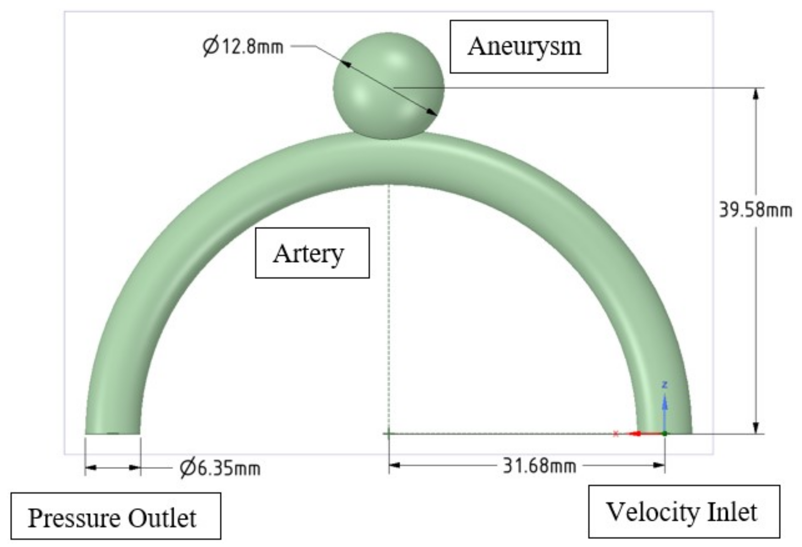
Figure 1. Symmetrical idealised cerebral artery and aneurysm geometry used for experimental and numerical study: illustrates the dimensions of the model and shows the 3D printed model used in PIV measurements.
Symmetry 14 00133 g001
Figure 2. Planar PIV schematic for setup used in the experimental study.
Symmetry 14 00133 g002
Figure 3. Boundary conditions used for both steady and state and pulsatile simulations.
Symmetry 14 00133 g003
Figure 4. Aneurysm-wall thrombin-release function vs. time.
Symmetry 14 00133 g004
Figure 5. Numbered locations 1-10 for 2D and 3D PIV simulation coordinate averages.
Symmetry 14 00133 g005
Figure 6. PIV comparison simulation inlet velocity profile.
Symmetry 14 00133 g006
Figure 7. PIV instantaneous velocity measurements: (a) Instantaneous velocity magnitude contours and vectors (m/s) of the entire artery at lower flow rate at inlet, (b) Instantaneous velocity magnitude contours and vectors (m/s) of the entire artery at higher flow rate at inlet, (c) Instantaneous velocity magnitude contours and vectors (m/s) of the aneurysm at lower flow rate at inlet and (d) Instantaneous velocity magnitude contours and vectors (m/s) of the aneurysm at higher flow rate at inlet.
Symmetry 14 00133 g007
Figure 8. Instantaneous PIV velocity measurements on planes of aneurysm: (a) velocity measurement on plane 2 [2 mm away from the middle plane] with flow rate at inlet Qin = 0.062 L/min; (b) Instantaneous PIV velocity measurement on plane 2 [2 mm away from the middle plane] with flow rate at inlet Qin = 0.077 L/min; (c) Instantaneous PIV velocity measurement on plane 3 [4 mm away from the middle plane] with flow rate at inlet Qin = 0.062 L/min; (d) Instantaneous PIV velocity measurement on plane 3 [4 mm away from the middle plane] with flow rate at inlet Qin = 0.077 L/min.
Symmetry 14 00133 g008
Figure 9. Pulsatile flow simulation centreline probe for thrombin concentration scalar output: comparison of different timesteps.
Symmetry 14 00133 g009
Figure 10. PIV and CFD comparison: (a) Experimental PIV velocity contour (m/s); (b) PIV simulation velocity contour (m/s).
Symmetry 14 00133 g010
Figure 11. Total thrombin amount within aneurysm over time.
Symmetry 14 00133 g011
Figure 12. Pulsatile and steady case comparison of areas with sufficient thrombin for clotting (>1 nM) represented in yellow: (a) pulsatile case at aneurysm wall (204 s); (b) steady case at aneurysm wall (204 s); (c) pulsatile case circulating in aneurysm (221 s); (d) steady case circulating in aneurysm (220 s); (e) pulsatile case entire aneurysm (224 s); (f) steady case entire aneurysm (223 s); (g) pulsatile case max thrombin (270 s); (h) steady case thrombin (270 s).
Symmetry 14 00133 g012
Figure 13. Pulsatile and steady case thrombin (nM) retention comparison with areas with sufficient thrombin for clotting (>1 nM) represented in yellow: (a) steady case thrombin distribution (224 s); (b) steady case velocity field (224 s); (c) pulsatile case thrombin leak from aneurysm 0.1 s after lower velocity peak (224.05 s); (d) pulsatile case velocity field (224.05 s); (e) pulsatile case thrombin distribution representative of majority of pulse (224.4 s); (f) pulsatile case velocity (224.4 s).
Symmetry 14 00133 g013
Figure 14. Pulsatile and steady case thrombin (nM) distribution comparison when sufficient thrombin for clotting (>1 nM) circulates in the aneurysm center and is represented in yellow: (a) pulsatile case (221 s); (b) steady case (220 s); (c) pulsatile case when pulsatile inlet function velocity (Figure 3) is equal to steady case inlet function and decreasing from upper velocity peak to lower velocity peak (221.15 s); (d) steady case (220.25 s); (e) pulsatile case when pulsatile inlet function (Figure 3) is at lower velocity peak (221.7 s); (f) steady case (220.5 s); (g) pulsatile case when pulsatile inlet function velocity (Figure 3) is equal to steady case inlet function and increasing from lower velocity peak to upper velocity peak (221.9 s); (h) steady case (220.75 s); (i) pulsatile case when pulsatile inlet function (Figure 3) is at upper velocity peak (222.05 s); (j) steady case at 221 s.
Symmetry 14 00133 g014
Table 1. Depiction of error from baseline mesh: Average deviation of meshes of varying refinement.
Error from Baseline Mesh
InletCentre-Axis Line ProbeOutlet Line Probe
Elements in MeshVelocityPressureVelocityPressureVelocityPressure
401,283 (Baseline)0%0%0%0%0%0%
203,3690%0.03%2.61%0.02%3.87%0.02%
100,0710%0.03%4.89%0.01%4.32%0.03%
Table 2. Average deviation of simulation from experimental PIV measurements.
PIV Simulation Deviation from Experimental Results
LocationVelocity Magnitude
16.46%
25.86%
316.10%
413.02%
59.46%
629.67%
78.63%
810.78%
97.48%
1021.21%
Average deviation12.87%
Publisher’s Note: MDPI stays neutral with regard to jurisdictional claims in published maps and institutional affiliations.