
Influence of Elastic–Plastic Deformation on the Structure and Magnetic Characteristics of 13Cr-V Alloyed Steel Pipe


Abstract
:1. Introduction
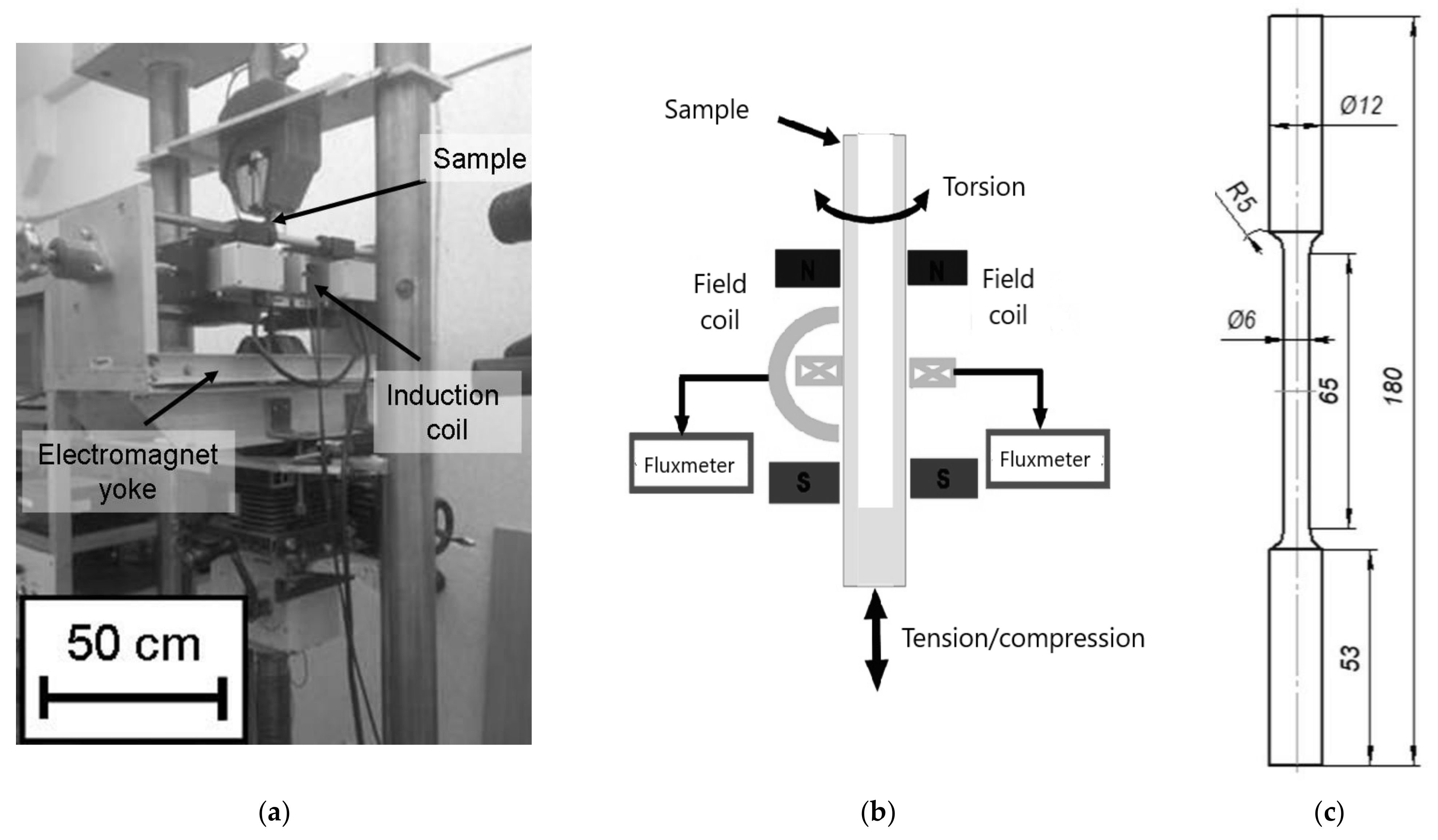
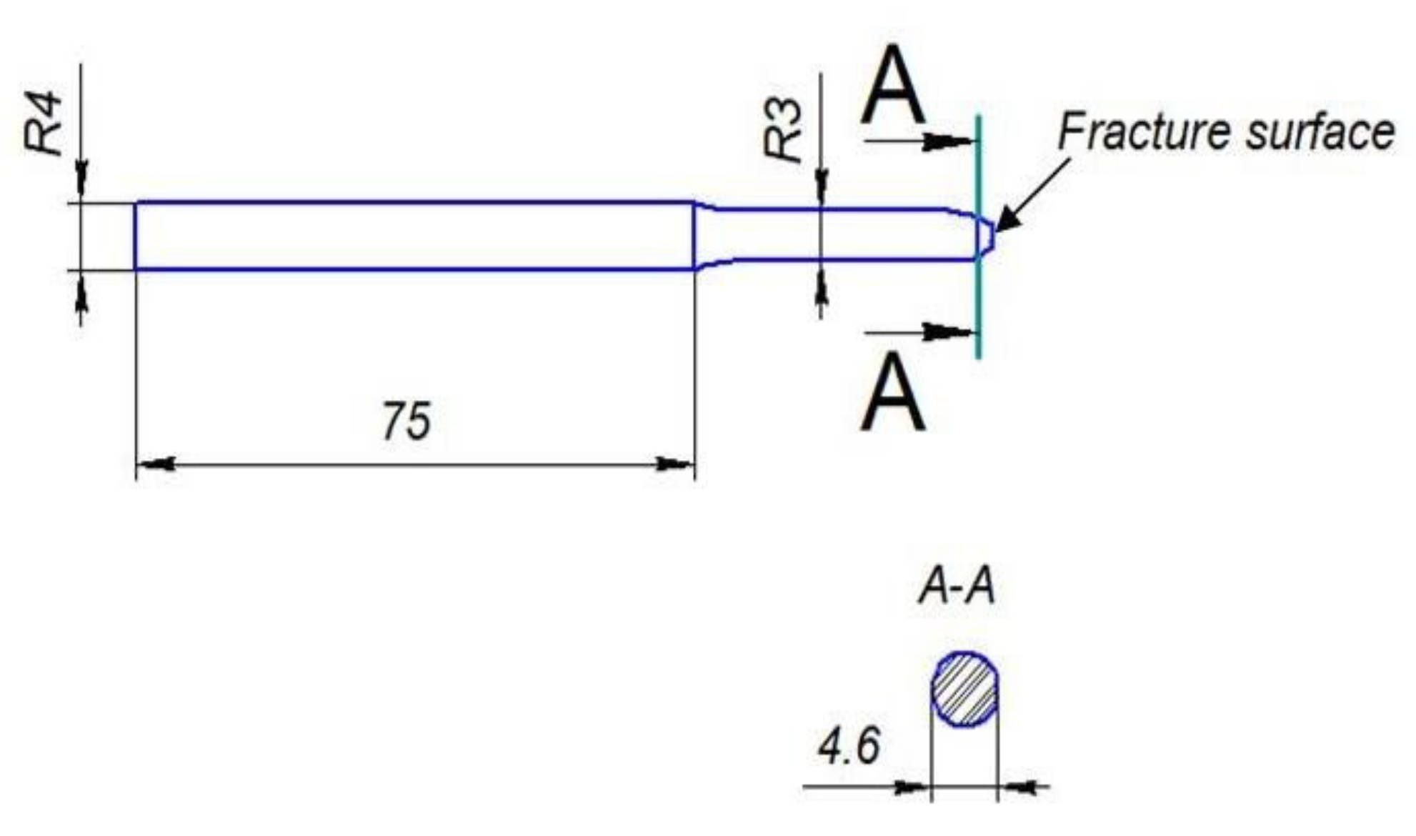
2. Materials and Methods
3. Results and Discussion
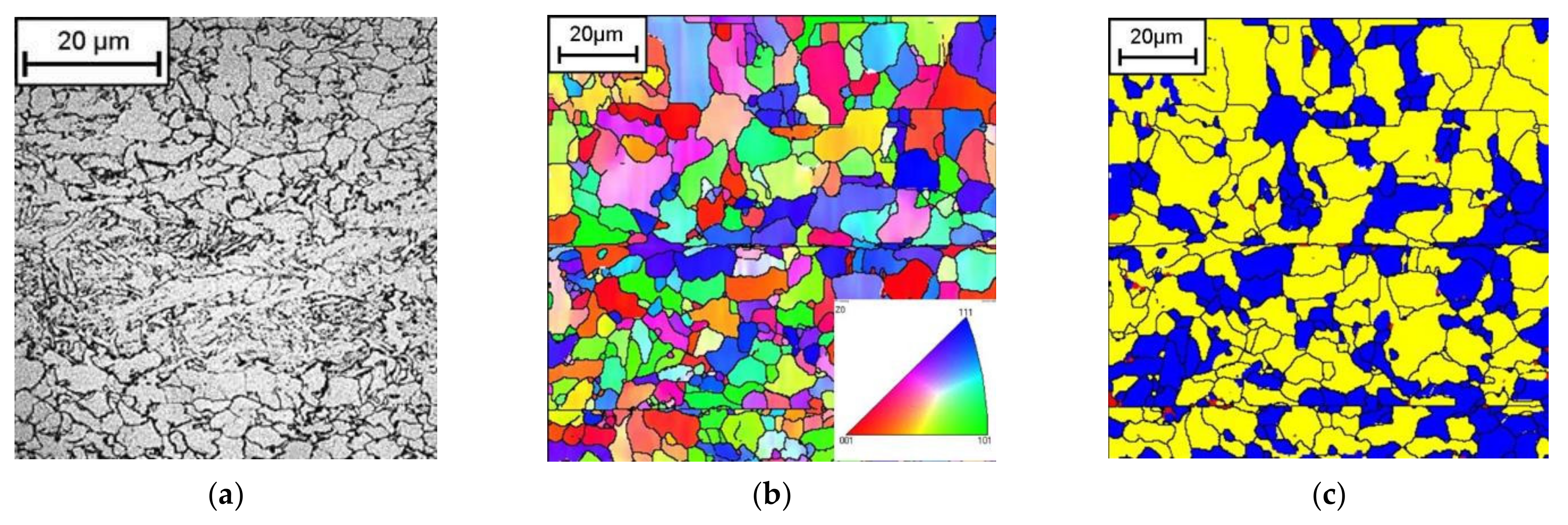
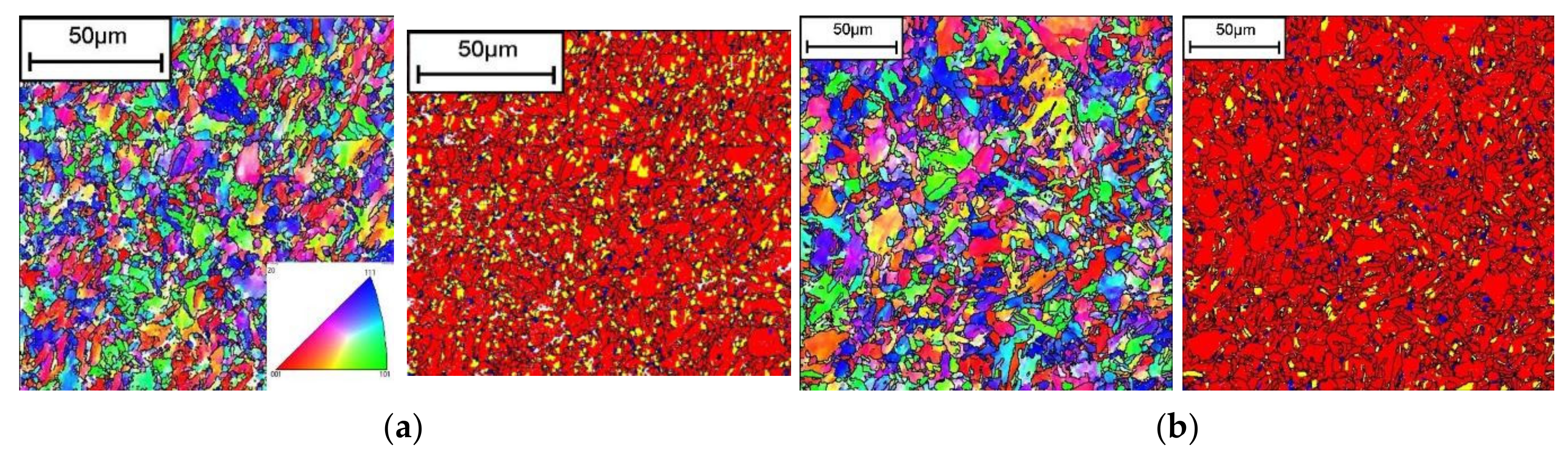
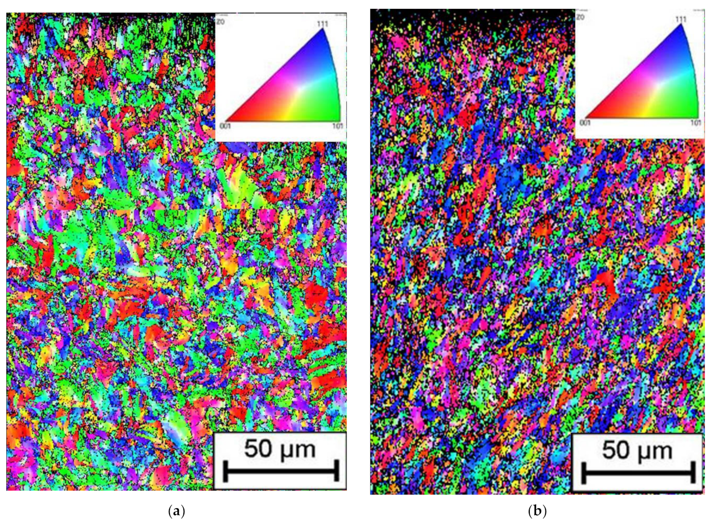
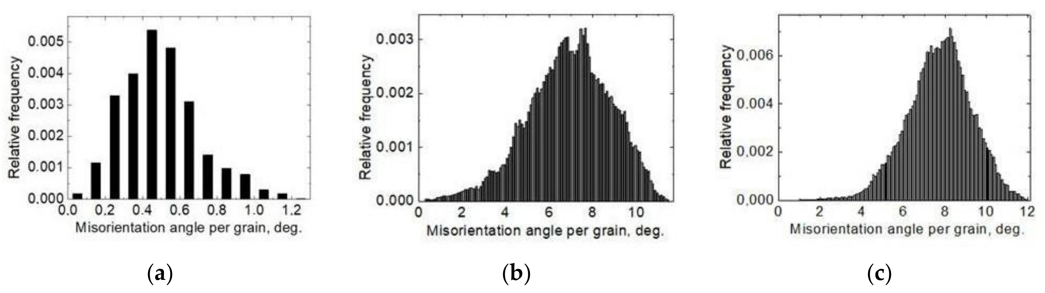
3.1. Microstructure Investigation
3.2. Investigation of Magnetic Properties
4. Conclusions
Author Contributions
Funding
Conflicts of Interest
References
- Liu, M.; Fan, Y.; Gui, X.; Hu, J.; Wang, X.; Gao, G. Relationship between Microstructure and Properties of 1380 MPa Grade Bainitic Rail Steel Treated by Online Bainite-Based Quenching and Partitioning Concept. Metals 2022, 12, 330. [Google Scholar] [CrossRef]
- Suetrong, C.; Uthaisangsuk, V. Investigations of fatigue crack propagation in ER8 railway wheel steel with varying microstructures. Mater. Sci. Eng. A 2022, 18, 142980. [Google Scholar] [CrossRef]
- Ohaeri, E.G.; Szpunar, J.A. An overview on pipeline steel development for cold climate applications. J. Pipeline Sci. Eng. 2022, 1, 1–17. [Google Scholar] [CrossRef]
- Efron, L.I. Material Science in “Big” Metallurgy. Pipe Steels; Metallurgizdat: Moscow, Russia, 2012; 696p. [Google Scholar]
- Wang, H.; Ge, Y.; Shi, L. Technologies in deep and ultra-deep well drilling: Present status, challenges and future trend in the 13th Five-Year Plan period (2016–2020). Nat. Gas Ind. B 2017, 4, 319–326. [Google Scholar] [CrossRef]
- Fan, Y.; Liu, T.G.; Xin, L.; Han, Y.M.; Lu, Y.H.; Shoji, T. Thermal aging behaviors of duplex stainless steels used in nuclear power plant: A review. J. Nucl. Mater. 2021, 544, 152693. [Google Scholar] [CrossRef]
- Hizli, H.; Hakan, C. Applicability of the Magnetic Barkhausen Noise Method for Nondestructive Measurement of Residual Stresses in the Carburized and Tempered 19CrNi5H Steels. Res. Nondestruct. Eval. 2018, 29, 221–236. [Google Scholar] [CrossRef]
- Kaijalainen, L.P.; Moilanen, M. Detection of plastic deformation during fatigue of mild steel by the measurements of Barkhausen noise. NDT Int. 1979, 12, 51–55. [Google Scholar] [CrossRef]
- Vengrinovich, V.; Vintov, D.; Prudnikov, A.; Podugolnikov, P.; Ryabtsev, V. Magnetic Barkhausen Effect in Steel Under Biaxial Strain/Stress: Influence on Stress Measurement. J. Nondestruct. Eval. 2019, 38, 52. [Google Scholar] [CrossRef]
- Mierczak, L.L.; Jiles, D.C.; Fantoni, G. A New Method for Evaluation of Mechanical Stress Using the Reciprocal Amplitude of Magnetic Barkhausen Noise. IEEE Trans. Magn. 2011, 2, 459–465. [Google Scholar] [CrossRef]
- Schajer, G.S. Practical Residual Stress Measurement Methods; John Wiley & Sons Ltd.: Vancouver, BC, Canada, 2013. [Google Scholar] [CrossRef]
- Chen, H.-E.; Xie, S.; Chen, Z.; Takagi, T.; Uchimoto, T.; Yoshihara, K. Quantitative Nondestructive Evaluation of Plastic Deformation in Carbon Steel Based on Electromagnetic Methods. Mater. Trans. 2014, 55, 1806–1815. [Google Scholar] [CrossRef] [Green Version]
- Kurz, J.H.; Szielasko, K.; Tschuncky, R. Micromagnetic and Ultrasound Methods to Determine and Monitor Stress of Steel Structures. J. Infrastruct. Syst. 2017, 2, B4016009. [Google Scholar] [CrossRef]
- Roskosz, M.; Fryczowski, K. Magnetic methods of characterization of active stresses in steel elements. J. Magn. Magn. Mater. 2020, 499, 166272. [Google Scholar] [CrossRef]
- Qiu, F.; Ren, W.; Tian, G.Y.; Gao, B. Characterization of applied tensile stress using domain wall dynamic behavior of grain-oriented electrical steel. J. Magn. Magn. Mater. 2017, 432, 250–259. [Google Scholar] [CrossRef]
- Takahashi, S.; Kobayashi, S.; Tomas, I.; Dupre, L.; Vertesy, G. Comparison of magnetic nondestructive methods applied for inspection of steel degradation. NDT E Int. 2017, 91, 54–60. [Google Scholar] [CrossRef] [Green Version]
- Scherbinin, V.E.; Gorkunov, E.S. Magnetic Quality Control of Metals; UB RAS: Ekaterinburg, Russia, 1996; 263p. [Google Scholar]
- Gorkunov, E.S.; MitropolskayaSYuVichuzhanin, D.I.; Tueva, E.A. Magnetic methods for estimation of loading and damaging in X70 steel. Phys. Mesomech. 2010, 1, 73–82. [Google Scholar]
- Mészáros, I.; Szabó, P.J. Complex magnetic and microstructural investigation of duplex stainless steel. NDT E Int. 2005, 7, 517–521. [Google Scholar] [CrossRef]
- Gorkunov, E.S.; Zadvorkin, S.M.; Kokovikhin, E.A.; Tueva, E.A.; Subachev, Y.u.V.; Goruleva, L.S.; Podkopytova, A.V. The effects of deformations by rolling and uniaxial tension on the structure and the magnetic and mechanical properties of armco iron, steel 12Cr1Nih10Ti, and a steel 12Cr1Nih10Ti-armco iron-steel 12Cr1Nih10Ti composite material. Russ. J. Nondestruct. Test. 2011, 6, 369–380. [Google Scholar] [CrossRef]
- Oršulová, T.; Palček, P.; Roszak, M.; Uhríčik, M.; Smetana, M.; Kúdelčík, J. Change of magnetic properties in austenitic stainless steels due to plastic deformation. Procedia Struct. Integr. 2018, 13, 1689–1694. [Google Scholar] [CrossRef]
- Gorkunov, E.S.; Putilova, E.A.; Zadvorkin, S.M.; Makarov, A.V.; Pecherkina, N.L.; Kalinin, G.Y.; Mushnikova, S.Y.; Fomina, O.V. Behavior of magnetic characteristics in promising nitrogen-containing steels upon elastoplastic deformation. Phys. Met. Metallogr. 2015, 8, 838–849. [Google Scholar] [CrossRef]
- Smirnov, S.V.; Shveikin, V.P. Plasticity and Deformability of Carbon Steels during Pressure Treatment; UB RAS: Ekaterinburg, Russia, 2009; 254p. [Google Scholar]
- Kolmogorov, V.L. Stress, Deformation, Destruction; Metallurgy: Moscow, Russia, 1970; 230p. [Google Scholar]
- Anastasiady, G.P.; Sil’nikov, M.V. Heterogeneity and Performance of Steel; Poligon: Saint Petersburg, Russia, 2002; 624p. [Google Scholar]
- Rybin, V.V. Large Plastic Deformations and Destruction of Metals; Metallurgia: Moscow, Russia, 1986; 224p. [Google Scholar]
- Zolotorevsky, N.Y.; Rybin, V.V. Fragmentation and Texture Formation during Deformation of Metallic Materials; Polytechnic University Press: Saint Petersburg, Russia, 2014; 207p. [Google Scholar]
- Gorkunov, E.S.; Mushnikov, A.N. Magnetic methods of evaluating elastic stresses in ferromagnetic steels (review). Test. Diagn. 2020, 12, 4–23. [Google Scholar] [CrossRef]
- Gorkunov, E.S. Influence of heat treatment on magnetostriction of structural steel 34Khn2M. Defektoskopiya 1979, 11, 105–108. [Google Scholar]
- Vonsovsky, S.V.; Schur, Y.S. Ferromagnetizm; OGIZ: Saint Petersburg, Russia, 1948; 816p. [Google Scholar]
- Dunaev, F.N. On the magnetic texture of elastically stretched transformer steel. Izv. Vuzov Phys. Ser. 1962, 1, 151–153. [Google Scholar]
- Zaykova, V.A.; Schur, Y.S. On the effect of tension on the magnetic properties and magnetostriction curves of silicon iron. Phys. Met. Metallogr. 1966, 5, 664–673. [Google Scholar]
- Kersten, M. Die Bedeutung der Koerzitivkraft. Probleme der Technischen Magnetisierungskurve; Becker, R., Ed.; Springer: Berlin, Germany, 1938; pp. 42–72. [Google Scholar]
- Gorkunov, E.S.; Zadvorkin, S.M.; Putilova, E.A.; Savrai, R.A. Effect of the Structure and Stress State on the Magnetic Properties of Metal in Different Zones of Welded Pipes of Large Diameter. Phys. Met. Metallogr. 2014, 10, 1011–1018. [Google Scholar] [CrossRef]


| C | Si | Mn | Cr | Ni | Mo | Cu | V | P | S |
|---|---|---|---|---|---|---|---|---|---|
| 0.04 | 0.31 | 0.65 | 0.56 | 0.09 | 0.01 | 0.15 | 0.06 | 0.006 | 0.002 |
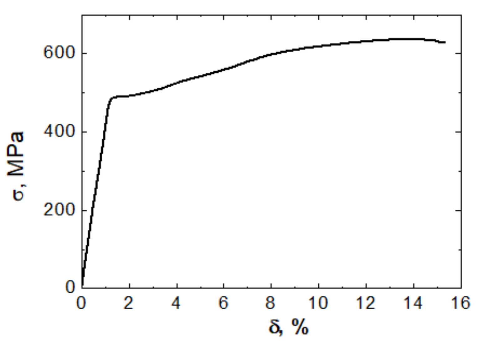
| Steel Grade | σY, MPA | σU, MPa | σY/σU | δ, % |
|---|---|---|---|---|
| 13Cr-V | 490 ± 25 | 640 ± 32 | 0.77 | 17 ± 1 |
Publisher’s Note: MDPI stays neutral with regard to jurisdictional claims in published maps and institutional affiliations. |
© 2022 by the authors. Licensee MDPI, Basel, Switzerland. This article is an open access article distributed under the terms and conditions of the Creative Commons Attribution (CC BY) license (https://creativecommons.org/licenses/by/4.0/).
Share and Cite
Putilova, E.; Kryucheva, K. Influence of Elastic–Plastic Deformation on the Structure and Magnetic Characteristics of 13Cr-V Alloyed Steel Pipe. Symmetry 2022, 14, 1201. https://doi.org/10.3390/sym14061201
Putilova E, Kryucheva K. Influence of Elastic–Plastic Deformation on the Structure and Magnetic Characteristics of 13Cr-V Alloyed Steel Pipe. Symmetry. 2022; 14(6):1201. https://doi.org/10.3390/sym14061201
Chicago/Turabian StylePutilova, Evgeniia, and Kristina Kryucheva. 2022. "Influence of Elastic–Plastic Deformation on the Structure and Magnetic Characteristics of 13Cr-V Alloyed Steel Pipe" Symmetry 14, no. 6: 1201. https://doi.org/10.3390/sym14061201
APA StylePutilova, E., & Kryucheva, K. (2022). Influence of Elastic–Plastic Deformation on the Structure and Magnetic Characteristics of 13Cr-V Alloyed Steel Pipe. Symmetry, 14(6), 1201. https://doi.org/10.3390/sym14061201