Article

Numerical Study on Thermal and Flow Characteristics of Divergent Duct with Different Rib Shapes for Electric-Vehicle Cooling System

1
Department of Mechanical Engineering, Dong-A University, 37 Nakdong-Daero 550, Saha-gu, Busan 49315, Korea
2
Gyeongnam Institute for Regional Program Evaluation, Evaluation Team, Room Number 405, 22 Changwon-daero 18beon-gil, Uichang-gu, Changwon-si 51395, Korea
*
Author to whom correspondence should be addressed.
These authors contributed equally to this work.
Symmetry 2022, 14(8), 1696; https://doi.org/10.3390/sym14081696
Submission received: 25 July 2022 / Revised: 9 August 2022 / Accepted: 12 August 2022 / Published: 16 August 2022
(This article belongs to the Section Computer)

Abstract

:
The cooling performance of the air-conditioning system in electric vehicles could be enhanced through the geometrical optimization of the air ducts. Furthermore, it has been proven that the heat-transfer performance of divergent channels is better than that of conventional channels. Therefore, the present study investigates the thermal and flow characteristics of divergent ducts with various rib shapes for the cooling system of electric vehicles. The thermal and flow characteristics, namely, temperature difference, pressure drop, heat-transfer coefficient, Nusselt number and friction factor, are numerically studied. Divergent ducts comprising ribs with the different shapes of rectangle, isosceles triangle, left triangle, right triangle, trapezoid, left trapezoid and right trapezoid arranged symmetrically are modeled as the computational domains. The thermal and flow characteristics of divergent ducts with various rib shapes are simulated in ANSYS Fluent commercial software for the Reynolds-number range of 22,000–79,000. The numerical model is validated by comparing the simulated results with the corresponding experimental results of the Nusselt number and the friction factor, obtaining errors of 4.4% and 2.9%, respectively. The results reveal that the divergent duct with the right-triangular rib shape shows the maximum values of the heat-transfer coefficient and Nusselt number of 180.65 W/m2K and 601, respectively. The same rib shape shows a pressure drop and a friction factor of 137.3 Pa and 0.040, respectively, which are lower than those of all rib shapes, except for the trapezoidal and right-trapezoidal rib shapes. Considering the trade-off comparison between thermal and flow characteristics, the divergent duct with the right-triangular rib shape is proposed as the best configuration. In addition, the effect of various conditions of the inlet air temperature on the thermal characteristics of the best configuration is discussed. The proposed results could be considered to develop an air-duct system with enhanced efficiency for electric vehicles.

1. Introduction

The wide range of applications of ducts in various fields has drawn considerable attention to improve their heat-transfer and flow performance characteristics. Research has proven that the convergent/divergent cross sections of ducts significantly influence their thermal performance; hence, research has been extended to this investigation. It is recognized that the inclusion of ribs is a promising technique that significantly improves the thermal performance of ducts [1,2]. Numerous research studies have been conducted to evaluate the effects of various rib configurations on the heat-transfer and frictional characteristics of fluid flow in ducts.
Taslim et al. analyzed the heat-transfer coefficient of round corner surfaces with low-aspect-ratio ribs considering the three ratios of rib height to channel hydraulic diameter of 0.133, 0.167 and 0.25 and the three pitch-to-height ratios (rib spacings) of 5, 8.5 and 10 under unheated- and heated-wall conditions [3]. Javadi et al. numerically investigated the Nusselt number, the friction factor, and the thermal and frictional entropy generation of ribbed ducts with rectangular, square, rectangular-trapezoidal, isosceles-trapezoidal, equilateral-triangular and non-equilateral-triangular shapes for the Reynolds-number range from 20,000 to 60,000. The study concluded that frictional entropy generation was maximum with the equilateral-triangular rib shape and minimum with the rectangular rib shape over the considered range of the Reynolds number [4]. Yongsiri et al. studied the heat-transfer and flow characteristics of channels with rib angles ranging from 0 ° to 165 ° . The study concluded that the rib angles of 60 ° and 120 ° showed higher heat-transfer performance for higher Reynolds numbers, whereas for lower Reynolds numbers, the influence of the rib angle was not significant [5]. Ghandouri et al. showed an improvement of 12.2 in heat-transfer performance and a weight reduction of 59% with corrugated fins compared with the conventional finned plate [6]. Ali et al. investigated the thermal and hydraulic performances of a microchannel heat sink with rectangular, zigzag and twisted fins for electronic cooling. The Nusselt number and the exergy efficiency of the microchannel heat sink with zigzag fins were 60% and 15% superior compared with the microchannel heat sink without fins [7]. Mokhtari et al. numerically studied the heat-transfer performance of horizontal channels with various fin arrangements. The study concluded that the cooling performance and temperature distribution were significantly affected by the fin arrangement. The inclined fin arrangement showed an enhancement in heat transfer of 40–50% in laminar flow and 15–20% in turbulent flow compared with the simple fin arrangement [8]. Sivakumar et al. numerically investigated the thermo-hydraulic performance characteristics of convergent and divergent channels with the different rib heights of 0, 1.5, 3, 6, 9 and 12 mm for the Reynolds-number range of 20,000–60,000. The heat-transfer performance increased for convergent and divergent channels compared with the uniform-cross-section channels [9]. Wang et al. compared the heat-transfer and pressure-drop characteristics of turbulent flow in square ducts with constant, convergent and divergent cross sections. The divergent cross section proposed superior heat-transfer characteristics followed by the constant and convergent cross sections, respectively [10]. Sivakumar et al. investigated the heat-transfer and friction characteristics of incompressible turbulent flow in rectangular divergent channels with five different configurations of square ribs. The rib height of 12 mm showed maximum heat transfer, and the friction factor decreased with the increase in the Reynolds number from 20,000 to 30,000 [11]. The influence of inclined ribs with angles from 30 ° to 90 ° , V-shaped ribs and inverted V-shaped ribs with angles of 45 ° and 90 ° on the thermal and frictional characteristics of stationary channels was investigated by Kaewchoothong et al. The results revealed that the Nusselt number was enhanced by 20%, 25% and 30% with the 60 ° inclined ribs, the 45 ° inclined ribs and the 60 ° V-shaped inclined ribs compared with the inclined ribs with an angle of 90 ° [12]. Lee et al. compared the thermal performance of rectangular divergent channels comprising ribs with different flow attack angles under the same conditions of mass flow rate, pressure drop and pumping power [13]. Stasiek et al. experimentally and numerically studied the heat-transfer and aerodynamic characteristics of air flow in channels with ribs provided in the form of turbulators [14]. The effect of the divider inclination angle in the range from −3 ° to +3 ° on the heat-transfer and flow characteristics of two-sided ribbed channels was investigated by Yan et al. for the Reynolds-number range from 10,000 to 50,000. The ribbed channel with the divider inclination angle of −1 ° showed superior thermal performance compared with other configurations [15]. Lee et al. studied the thermal performance of four convergent/divergent one-sided ribbed channels with diameter ratios of 0.67, 0.86, 1.16 and 1.49. The study concluded that both divergent channels showed superior thermal performance under identical conditions of mass flow rate, pressure drop and pumping power [16]. Abraham and Vedula compared the thermal performance of square converging channels obtained with straight ribs, V-shaped ribs and W-shaped ribs for the Reynolds-number range from 5000 to 35,000. The results show that the W-shaped ribs proposed enhanced the heat-transfer coefficient compared with the V-shaped ribs [17]. The effects of the rectangular, triangular, wedge-point-upstream and wedge-point-downstream rib shapes in in-line and staggered configurations on the heat-transfer performance characteristics of fluid flow in constant-cross-section channels were investigated by Vanaki and Mohammed for the Reynolds-number range from 5000 to 20,000 and the heat flux of 10 kW/m2 [18]. Zheng et al. proposed a numerical model to simulate the heat-transfer and flow characteristics of six ribs with different structures in square cross-section channels under uniform heat flux and for the Reynolds-number range from 8000 to 24,000 [19]. Lu and Jiang concluded that the rectangular channel with 60 ° ribs depicted a superior heat-transfer coefficient; however, that with 20 ° ribs showed excellent overall performance considering heat-transfer and pressure-drop characteristics [20]. Zheng et al. investigated the thermal performance in internal cooling of channels with ribs with different convergent/divergent angles and slit shapes. The trapezoidal slit with the smallest angle showed an excellent thermal-performance index in terms of higher heat transfer and lower pressure drop [21].
Air ducts are widely used in the heating, ventilation and air-conditioning (HVAC) system of electric vehicles, whereas flow channels are important parts of the fuel cells of electric vehicles. The shape and structure of air ducts could be optimized to design an efficient HVAC system, which could result in driving-range and reliability enhancements for electric vehicles [22]. Furthermore, optimizing the geometry and structure of flow channels could enhance efficiency to improve the reliability and performance of the fuel cells of electric vehicles. Dong et al. proposed flow channels for proton-exchange membrane (PEM) fuel cells with S-shaped and crescent ribs to improve the flow field and the convective effect. The electrochemical efficiency was improved by 23.61%, and the pressure drop was reduced for the proposed fuel cell compared with the flow channels with sinusoidal ribs [23]. Chowdhury and Timurkutluk replaced convectional serpentine flow channels in proton-exchange-membrane fuel cells with convergent and divergent serpentine flow channels. Uniform current density and better oxygen mass transport were observed in the convergent serpentine flow channels compared with the conventional and divergent serpentine flow channels [24].
To improve the performance of electric vehicles, the cooling channels for thermal management, the air ducts of HVAC systems and the flow channels in fuel cells should be effectively designed such that they show excellent heat-transfer characteristics. Numerous research studies have investigated the performance of conventional straight channels/ducts with various rib shapes. The open literature also reveals that heat-transfer performance could be enhanced by replacing straight channels/ducts with divergent channels, as concluded by Lee et al. in their experimental study [16]. However, there have been no attempts to investigate the heat-transfer performance of divergent channels considering various rib geometries. Therefore, the present study proposes a numerical investigation of the thermal and flow characteristics of divergent ducts with symmetrically arranged ribs of various shapes. Divergent ducts with the various rib shapes of rectangle, isosceles triangle, left triangle, right triangle, trapezoid, left trapezoid and right trapezoid are modeled. The numerical models are developed in ANSYS fluent commercial software, and the simulated results of thermal and flow characteristics are validated with experimental results. The temperature difference, pressure drop, heat-transfer coefficient, Nusselt number and friction factor are numerically simulated and compared for various rib shapes under the influence of Reynolds numbers. The best configuration of divergent duct and rib shape is proposed based on a trade-off comparison between thermal and flow characteristics. In addition, the thermal characteristics of the divergent duct with the best rib shape are investigated under the effects of the inlet air temperature to suggest the optimum temperature conditions. The database generated from the present investigation on ducts with various rib shapes could be referred to as a guideline while designing air-duct cooling systems for electric vehicles.

2. Numerical Method

The numerical method describes the computational geometry considered for the present study followed by the elaboration of meshing, the governing equations, the boundary conditions, the assumption with the solution procedure and the data reduction in Section 2.1, Section 2.2, Section 2.3, Section 2.4, Section 2.5 and Section 2.6, respectively.

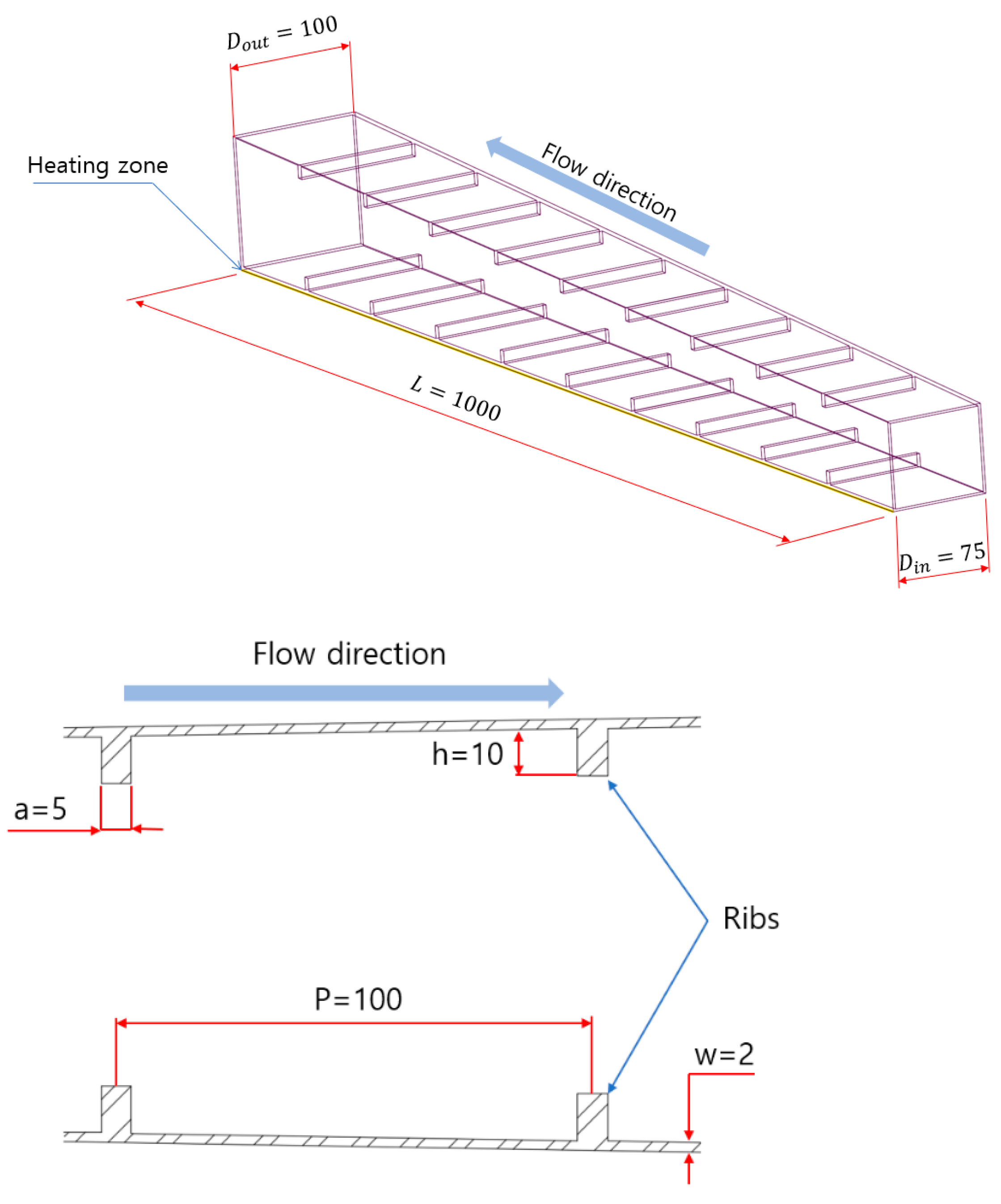
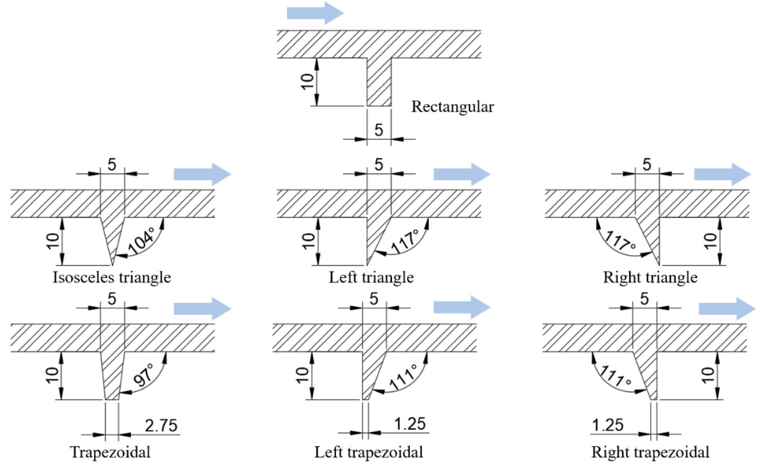
2.1. Computational Geometry
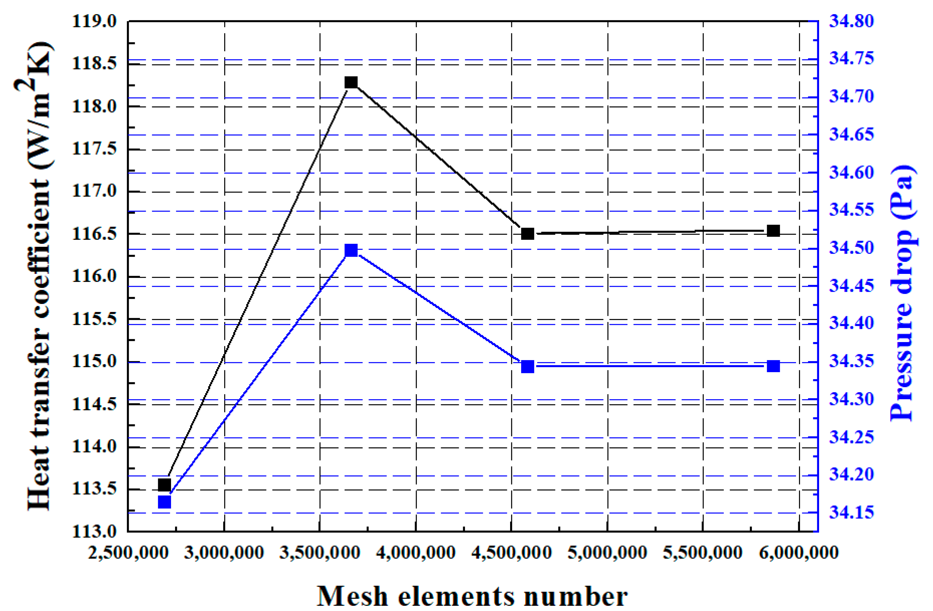
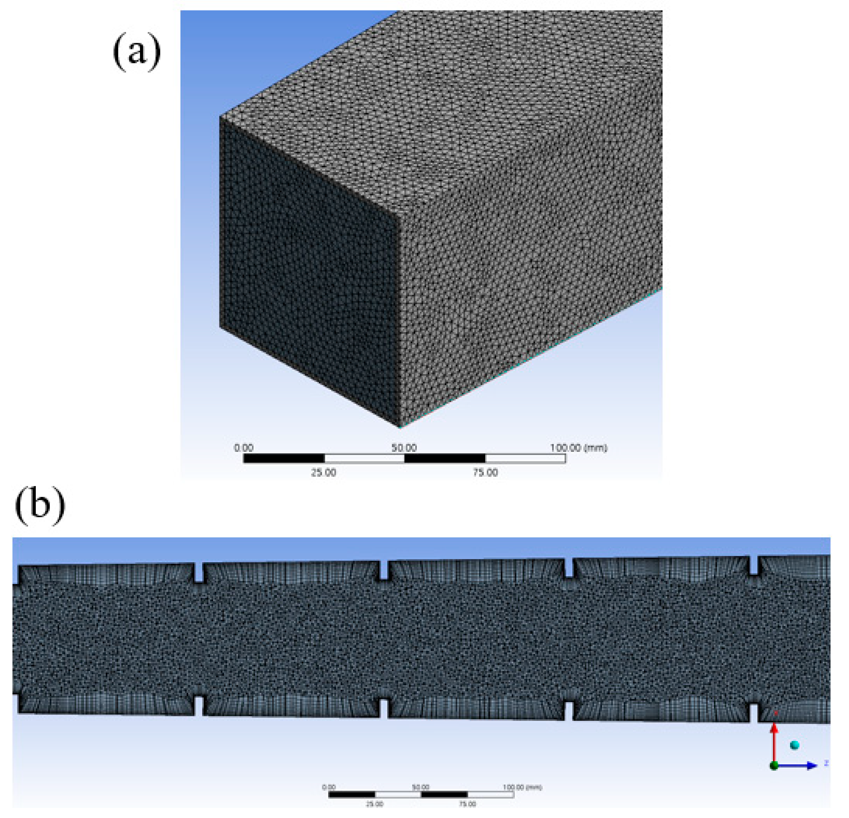
A divergent-duct system as shown in Figure 1 is considered as the computational domain to investigate the thermal and flow characteristics of constant and fully developed flow. The hydraulic diameters of the duct at the inlet and outlet zones are 75 mm and 100 mm, respectively. The length of the duct is 1000 mm, and the thickness of the wall along its entire length is 2 mm. The material of the duct is considered to be copper, and air is considered as the working fluid. The rectangular ribs are provided symmetrically on the top and bottom walls of the duct. The base length and height of the rectangular ribs are 5 mm and 10 mm, respectively. The center-to-center distance between the base of each rib is 100 mm, so there are a total of 18 ribs in the duct. Constant heat flux is enabled at the outer bottom wall of the duct. The effects of different rib shapes, namely, rectangular, isosceles triangular, left triangular, right triangular, trapezoidal, left trapezoidal and right trapezoidal, as shown in Figure 2, on thermal and flow characteristics are studied. The Ansys fluent commercial code is used to simulate and compare the thermal and flow characteristics of divergent-duct systems with various rib shapes.

2.2. Meshing

The computational domain is meshed with tetrahedral mesh elements with different element sizes of 2.3 mm, 2.5 mm, 2.7 mm and 3.0 mm. The inflation layers are provided in the fluid domain to consider the effect of boundary layers near the ribs. The specifications of inflation are a number of layers of 5, a transition ratio of 0.4 and a growth rate of 1.2. Furthermore, to incorporate the impact of vortices generated in the air flow near the ribs, these sections are meshed with finer mesh elements of a size of 0.8 mm. The mesh independency test is conducted considering four element sizes for computational geometry in order to assure the balance between computational time and accuracy [25]. The mesh independency test is performed for divergent ducts with all rib shapes; however, the results for the divergent duct with the rectangular rib shape is depicted in Figure 3, which is the same as the experimental geometry. The mesh independency test is performed at an inlet air temperature of 304.15 K and the maximum inlet velocity corresponding to the Reynolds number of 79,000. The number of elements corresponding to four element sizes are depicted in Table 1. The heat-transfer characteristics of the heat-transfer coefficient and pressure drop are simulated for various element numbers. The simulated results for various mesh-element numbers are shown in Figure 3. Beyond the mesh-element number of 4,579,698, the simulated results of the heat-transfer coefficient and pressure drop converge. Hence, the mesh-element number of 4,579,698 is adopted for computational geometry in further simulations. The meshing for the computational domain of the divergent duct with the rectangular rib shape is shown in Figure 4. The meshing depicted in Figure 4 is adopted with a mesh-element number of 4,579,698 after the mesh independency test.
One of the values that describes the mesh quality used for simulating fluid flow is a non-dimensional distance between the examined duct wall and the initial mesh node and is denoted as y+. Thus, for obtaining more accurate results, the y+ number should be in range from 1 to 10 [26]. In the present simulation, for the adopted mesh, the y+ number is 8, as shown in Figure 5, which is in the acceptable range.

2.3. Governing Equations

The continuity, momentum and energy equations as presented in (1)–(3) are used to simulate the thermal and flow characteristics of the divergent-duct system with air as the working fluid. The conduction in the solid parts of a divergent duct including walls and ribs is governed by Equation (4) [27,28]:
· ( ρ V ) = 0
· ( ρ V × V ) = p + μ ( 2 V ) + S M
· ( ρ V h ) = · ( λ T ) + S E
· ( λ T ) s + q ˙ = 0
To depict the consequences of turbulent-flow conditions, the k-omega ( ω ) turbulence model is used in the present simulations. The k - ω turbulence model is presented in Equations (5)–(17). The turbulent kinetic energy ( k ), which defines the energy in turbulence, and the particular turbulent dissipation rate ( ω ), which determines the rate of dissipation per unit of turbulent kinetic energy, are the two conveyed variables. ω is also regarded as the turbulence scale. The turbulence related to the fluid flow in the divergent duct is solved by selecting the k - ω turbulence model in ANSYS Fluent software. The values of turbulent parameters and coefficients as presented in (13)–(17) are incorporated in ANSYS software to manipulate the related equations [29,30].
Kinematic eddy viscosity:
v T = a 1 k max ( a 1 ω , S F 2 )
Turbulence kinetic energy:
k t + U j k x j = P k β * k ω + k t [ ( v + σ T v T ) k x j ]
Specific dissipation rate:
ω t + U j ω x j = α S 2 β ω 2 + x j [ ( v + σ ω v T ) ω x j ] + 2 ( 1 F 1 ) σ ω 2 1 ω k x i ω x i
F 1 (blending function):
F 1 = tanh { { m i n [ max ( k β * ω y , 500 v y 2 ω ) , 4 σ ω 2 k C D k ω y 2 ] } 4 }
C D k ω
C D k ω = max ( 2 ρ σ ω 2 1 ω k x i ω x i , 10 10 )
F 2 (second blending function):
F 2 = tanh [ [ max ( 2 k β * ω y , 500 v y 2 ω ) ] 2 ]
P K (production limiter):
P K = min ( τ i j U i x j , 10 β * k ω )
The closure coefficients appearing in the model are specified as:
ϕ = ϕ 1 F 1 + ϕ 2 ( 1 F 1 )
α 1 = 5 9 , α 2 = 0.44
β 1 = 3 40 , β 2 = 0.0828
β * = 9 100
σ k 1 = 0.85 , σ k 2 = 1
σ ω 1 = 0.5 , σ ω 2 = 0.856

2.4. Boundary Conditions

The heating input employed at the outer bottom wall of the duct is 235 W based on the experimental study presented by Lee and Ahn [31]. This heating input is converted into heat flux as W/m2 based on the bottom surface area of the duct. The temperature of air at the inlet of the duct is set to 304.15 K. The air velocity at the inlet of the duct is set as per the Reynolds-number range of 22,000–79,000. The turbulence intensity level is set as 10% with a hydraulic-diameter length scale of 0.0875 m. The properties of the air working fluid and the copper material are shown in Table 2 [32]. The boundary conditions are summarized as follows:
Q = 235   W
T i = 304.15   K
5.12   m / s < U i < 17.89   m / s

2.5. Assumptions and Solution Procedure

The SIMPLE (Semi-Implicit Method with Pressure-Linked Equation) algorithm is used to solve the pressure–velocity coupling. The pressure correlations are dealt with using the PRESTO scheme. The second-order upwind scheme is used to solve the Navier–Stokes equations. All governing equations are solved using the finite volume method in the ANSYS Fluent commercial code based on the stated boundary conditions and assumptions. The fluid flow in the divergent channel is assumed to be three-dimensional, steady state, incompressible and turbulent.

2.6. Data-Reduction Equations

The total heat-transfer coefficient is determined using the overall net heat-transfer rate and the difference between the wall temperature and the bulk mean air temperature [31]:
h T = ( Q Q l o s s ) A ( T w T b )
Equation (22) is used to calculate the bulk temperature of air [31]:
T b = T i ( Q Q l o s s ) A A m ˙ C p
The average Nusselt number is evaluated using Equation (23) [33]:
N u = h T D i n k f
The Reynolds number is defined by Equation (24) [34]:
R e = u b m D h m v
The diverging channel’s total friction factor is evaluated using Equation (25) [31]:
f T = D h m 2 ρ u b m 2 | Δ P e L |

3. Results and Discussion
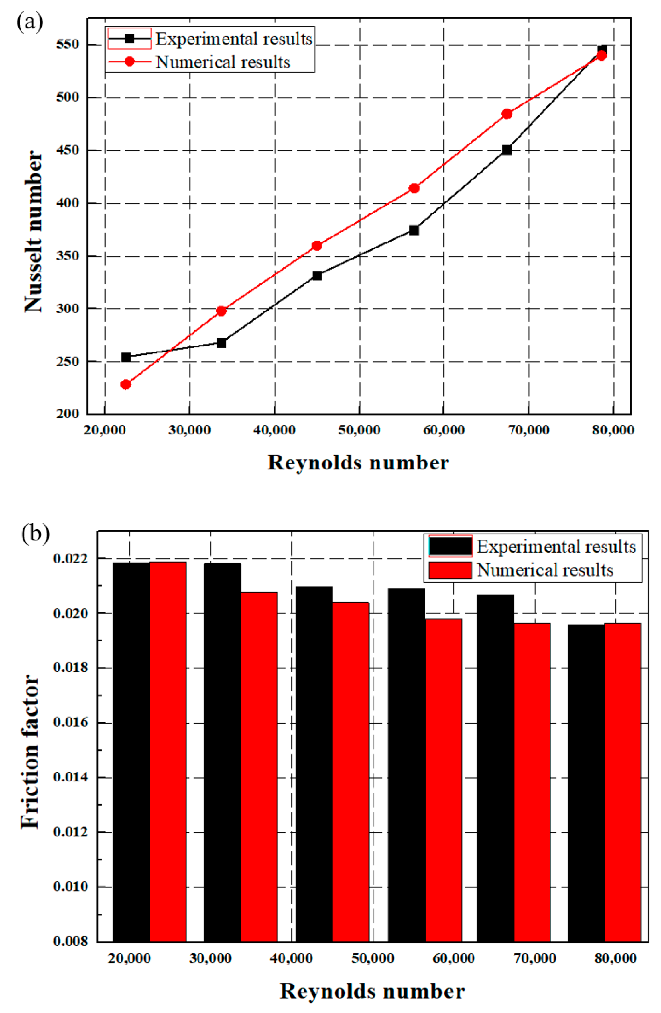
The numerical model is validated in terms of the thermal and flow characteristics in this section. The thermal and flow characteristics of the temperature difference, heat-transfer coefficient, Nusselt number, pressure drop and friction factor are discussed for divergent ducts with various rib shapes under the influence of the Reynolds number. Furthermore, the effect of the inlet temperature of air on the thermal characteristics of divergent ducts with various rib shapes is elaborated in this section.

3.1. Validation

To assure the accuracy and reliability of the numerical model, the simulated results are compared with the experimental results presented by Lee and Ahn [31]. They conducted an experimental study on straight, convergent and divergent ducts with rectangular ribs. The thermal and flow characteristics were investigated for various duct cross sections with one-sided and two-sided rib structures under the influence of different Reynolds numbers. The study concluded that the divergent duct with the two-sided rib structure showed excellent heat-transfer performance compared with straight and convergent ducts. Therefore, in the present study, the best structure of a divergent duct with a two-sided rectangular rib structure is adopted for validation and further modifications with various rib geometries. The same configuration of the divergent channel and operating conditions used in the experimental study are reflected in the present numerical study. The objective of the present work is to modify the structure of the proposed best configuration of a divergent duct with the two-sided rectangular rib structure in the experimental study by Lee and Ahn considering various rib shapes in order to further improve the heat-transfer performance based on a numerical approach. The simulated results of the Nusselt number and the friction factor are compared with the corresponding experimental results. The comparison of experimental and simulated results is presented in Figure 6. For the Reynolds-number range of 22,000–79,000, the average errors between the experimental and simulated results of the Nusselt number and friction factor are 4.4% and 2.9%, respectively. The simulated results deviate within a 5% average error and a 10% maximum error compared with the experimental results. Hence, the developed numerical model is accepted for further simulations considering divergent ducts with different rib shapes under the influence of various boundary conditions.

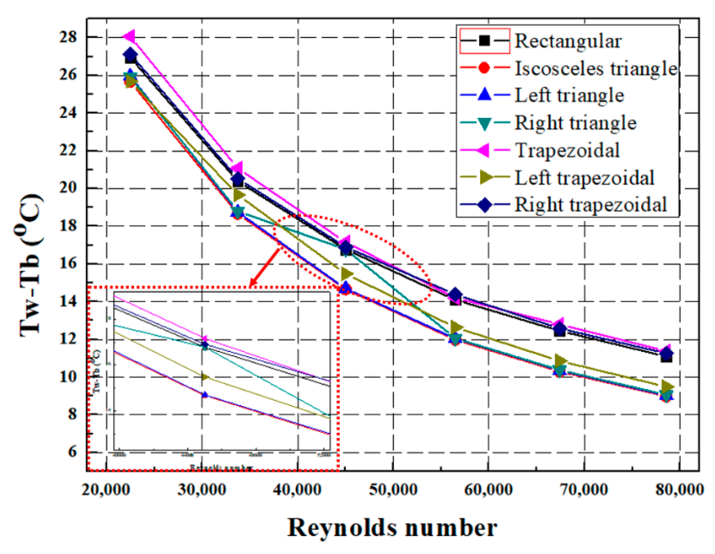
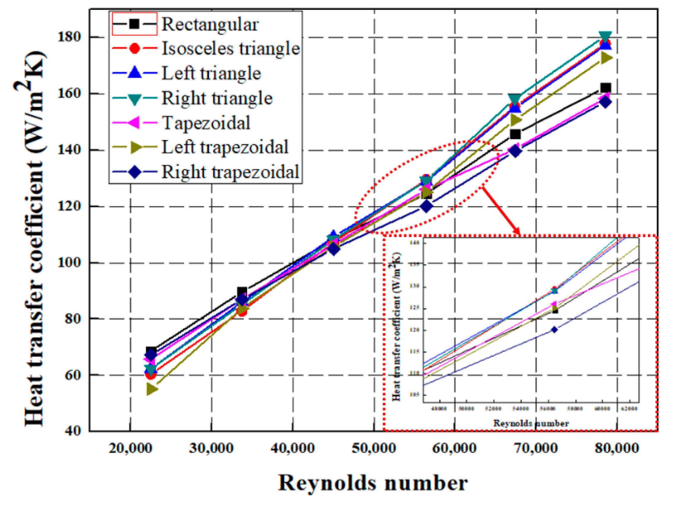
3.2. Thermal Characteristics

The variation in the difference between the wall temperature and the fluid temperature with the Reynolds number for divergent ducts with various rib shapes is shown in Figure 7. A greater difference between the wall temperature and the air temperature indicates that the air carries a lower amount of heat when passing from the inlet to the outlet of the duct, whereas a smaller difference between the wall temperature and the air temperature indicates that the air absorbs a greater amount of heat while moving from the inlet to the outlet of the duct. The heat-transfer rate is maximum at higher Reynolds numbers because of the increase in turbulence, which indicates that the temperature difference between wall and air is greater at lower Reynolds numbers and decreases with the increase in the Reynolds number. Xie et al. showed the same results of the decrease in the difference between the wall temperature and the fluid temperature with the increase in the Reynolds number [35]. The smallest temperature difference is observed for the isosceles triangle followed by the left trapezoid, right triangle, left triangle, rectangle, right trapezoid and trapezoid, respectively, in increasing order. For the Reynolds-number range of 22,483–78,559, the temperature differences range from 11.10 °C to 26.95 °C, from 8.99 °C to 25.67 °C, from 9.03 °C to 25.97 °C, from 9.07 °C to 25.93 °C, from 11.38 °C to 28.07 °C, from 9.49 °C to 25.69 °C and from 11.27 °C to 27.13 °C for the rectangular, isosceles-triangular, left-triangular, right-triangular, trapezoidal, left-trapezoidal and right-trapezoidal rib shapes, respectively.
The heat-transfer coefficient for divergent ducts with various rib shapes is compared in Figure 8. The variation in the heat-transfer coefficient is presented with the Reynolds number for all rib shapes. The heat-transfer coefficient increases when the heat transfer from the duct to the air increases through conduction and convection. The air absorbs more heat at higher Reynolds numbers owing to the increase in the degree of turbulence, which results in a smaller temperature difference between wall and air and thus an enhancement in the heat-transfer coefficient. The increase in the Reynolds number creates a higher degree of turbulence, which results in an enhancement in the heat gain when air passes from the inlet to the outlet of the duct for all rib shapes. Therefore, the divergent duct with each rib shape shows an increase in the heat-transfer coefficient with the increase in the Reynolds number. With the increase in the Reynolds number from 22,483 to 78,559, the heat-transfer coefficients increase from 68.68 W/m2K to 162.30 W/m2K for the rectangular rib shape, from 60.42 W/m2K to 177.87 W/m2K for the isosceles-triangular rib shape, from 62.31 W/m2K to 177.25 W/m2K for the left-triangular rib shape, from 62.31 W/m2K to 180.65 W/m2K for the right-triangular rib shape, from 65.77 W/m2K to 158.42 W/m2K for the trapezoidal rib shape, from 55.18 W/m2K to 172.87 W/m2K for the left-trapezoidal rib shape and from 67.31 W/m2K to 157.21 W/m2K for the right-trapezoidal rib shape. The obstruction of air flow in the case of the right-triangular rib shape imposes a larger degree of turbulence than other rib shapes. Therefore, a superior heat-transfer rate is depicted by the divergent duct with the right-triangular rib shape compared with those obtained with other rib shapes. The maximum heat-transfer coefficient is depicted for the right-triangular rib shape followed by the isosceles-triangular, left-triangular, left-trapezoidal, rectangular, trapezoidal and right-trapezoidal rib shapes, respectively, in decreasing order. Javadi et al. concluded that the triangular rib shape in the case of a constant cross-section duct showed better thermal performance than the rectangular, square and trapezoidal rib shapes [4].
The Nusselt-number comparison for divergent ducts with various rib shapes under influence of the Reynolds number is depicted in Figure 9. The Nusselt number depends on the heat-transfer coefficient; hence, a higher heat-transfer coefficient results in higher Nusselt numbers, and the decrease in the heat-transfer coefficient results in lower Nusselt numbers. The rib shape that shows the highest heat-transfer coefficient has the highest value of the Nusselt number. Therefore, the trends of the variation in the Nusselt number are same as those of the heat-transfer coefficient for all rib shapes. The right-triangular rib shape shows the highest value of the Nusselt number, followed by the isosceles-triangular, left-triangular, left-trapezoidal, rectangular, trapezoidal and right-trapezoidal rib shapes, respectively, in decreasing order of the Nusselt number, because the heat-transfer coefficient for these rib shapes decreases in the same order of the decrease in the heat-transfer rate. The Nusselt number increases with the increase in the Reynolds number because of the increase in the heat-transfer coefficient for all shapes. The Nusselt numbers increase in the ranges from 228 to 540, from 201 to 592, from 207 to 590, from 207 to 601, from 219 to 527, from 184 to 575 and from 224 to 523, for the rectangular, isosceles-triangular, left-triangular, right-triangular, trapezoidal, left-trapezoidal and right-trapezoidal rib shapes, respectively, over the Reynolds-number range from 22,483 to 78,559. Taslim and Wadsworth also showed the same trend of the Nusselt number with the Reynolds number; with the increase in the Reynolds number, the Nusselt number of square channels with ribs increased [36].

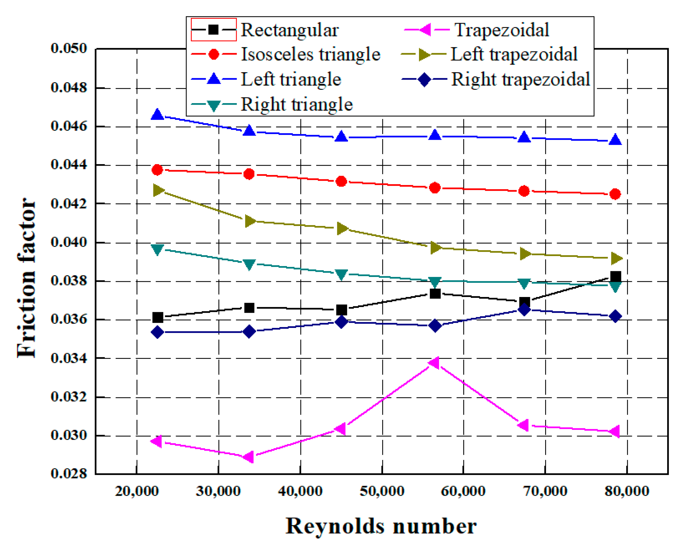
3.3. Flow Characteristics

The comparison of the pressure drop for divergent ducts with various rib shapes over the variation range of the Reynolds number is presented in Figure 10. As mentioned, the increase in the Reynolds number increases the degree of turbulence of air flow in the duct, which results in the increase in heat transfer at the cost of the increase in the pressure drop. This is the reason for the increase in the pressure drop for all rib shapes with the increase in the Reynolds number. The trapezoidal rib shape creates a lower degree of turbulence for air flow, which results in the lowest pressure drop, whereas the left triangle depicts the maximum pressure drop owing to the greater turbulence generated by this rib shape. All other rib shapes present turbulence degrees between the left-triangular and trapezoidal rib shapes; hence, the pressure drops for these rib shapes lie between maximum and minimum values imposed by the left-triangular and trapezoidal rib shapes, respectively. In the variation range of the Reynolds number from 22,483 to 78,559, the pressure drops for the rectangular, isosceles-triangular, left-triangular, right-triangular, trapezoidal, left-trapezoidal and right-trapezoidal rib shapes are from 10.8 Pa to 139.1 Pa, from 13.0 Pa to 154.52 Pa, from 13.9 Pa to 164.5 Pa, from 11.8 Pa to 137.3 Pa, from 8.9 to 109.9 Pa, from 12.7 Pa to 142.5 Pa and from 10.5 to 131.6 Pa, respectively. Ali et al. showed an increment in the pressure drop with the increase in the Reynolds number; the pressure drop increased from 30 kPa to 120 kPa with the rise in the Reynolds number from 100 to 350 [7].
The behavior of the friction factor over the variation range of the Reynolds number for divergent ducts with different rib shapes is shown in Figure 11. For each rib shape, the variation trend of the friction factor is not the same as that of the pressure drop, because the friction factor depends on the pressure drop as well as the velocity of air. There is no specific increasing or decreasing trend for the friction factor with the Reynolds number for the various rib shapes. The left trapezoid shows a decrease in the friction factor as the Reynolds number increases, whereas there is a critical Reynolds number for the trapezoidal rib shape, where the friction factor is maximum. The pressure drop is lower for the trapezoidal rib shape, which results in the lowest values of the friction factor over the entire range of Reynolds numbers. The maximum friction factor is evaluated for the left triangle because of the higher pressure drop over the variation range of the Reynolds number. Over the variation range from 22,483 to 78,559 for the Reynolds number, the friction factors vary in the ranges from 0.036 to 0.038, from 0.043 to 0.044, from 0.045 to 0.047, from 0.038 to 0.040, from 0.029 to 0.034, from 0.039 to 0.043 and from 0.035 to 0.037 for the rectangular, isosceles-triangular, left-triangular, right-triangular, trapezoidal, left-trapezoidal and right-trapezoidal rib shapes, respectively. Taslim and Korotsky also claimed that there exists a critical point for the Reynolds number where the friction factor is maximum [3].
The discussion presented in Section 3.2 and Section 3.3 above indicates that the divergent duct with the right-triangular rib shape shows excellent thermal performance characteristics with superior values of heat-transfer coefficient and Nusselt number among all rib shapes. Furthermore, the pressure drop for the divergent duct with the right-triangular rib shape is higher than that with the trapezoidal and right-trapezoidal rib shapes; however, it is lower than those obtained with all other rib shapes. Hence, the trade-off comparison between thermal and flow performance characteristics shows that the divergent duct with the right-triangular rib shape is the best configuration to achieve enhanced heat-transfer performance. For better visualization, the comparison of the velocity streamlines for the divergent duct with the rectangular and right-triangular rib shapes is depicted in Figure 12. The flow is superiorly developed in the case of the divergent duct with the right-triangular rib shape compared with the rectangular rib shape. However, a symmetrical velocity distribution is observed for both rib shapes. The degree of turbulence is higher in the case of the right-triangular rib shape owing to the velocity in the flow region being higher than in the rectangular rib shape.

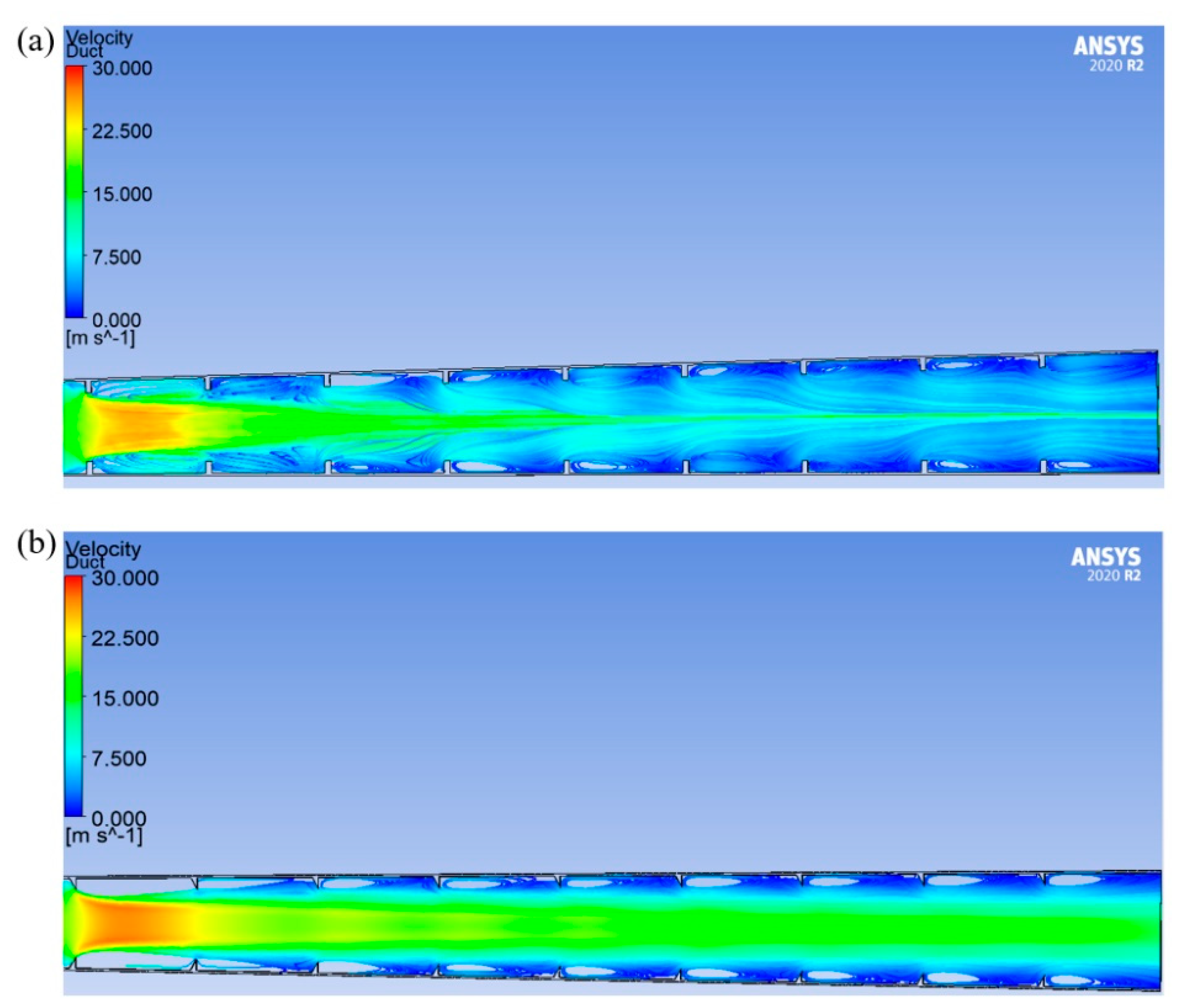
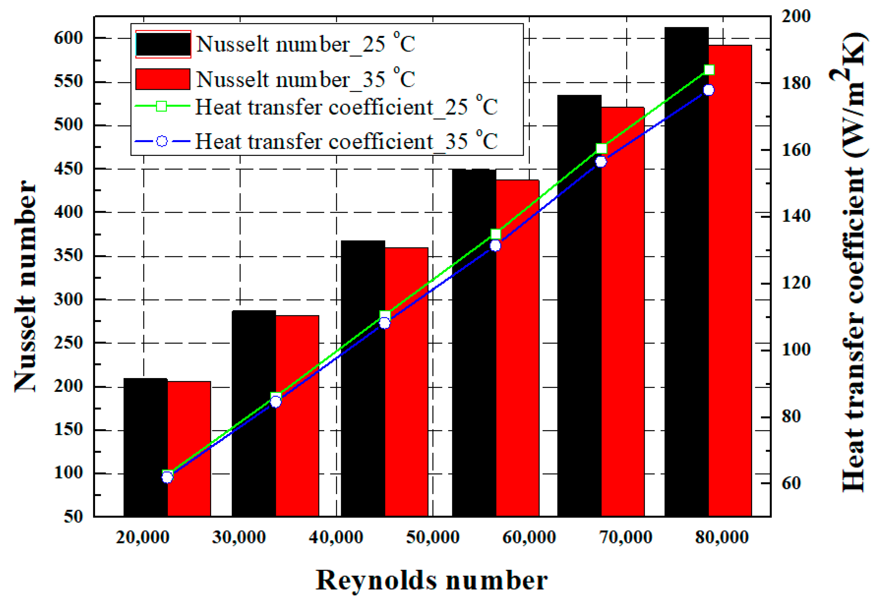
3.4. Effect of Inlet Air Temperature

The influence of the change in the inlet air temperature is evaluated on the thermal characteristics of the best configuration, i.e., the divergent duct with the right-triangular rib shape. The behaviors of the heat-transfer coefficient and the Nusselt number are investigated as thermal characteristics. The flow characteristics do not significantly change with the change in the inlet air temperature; hence, this is not elaborated in this section. The variations in the heat-transfer coefficient and the Nusselt number with the Reynolds number for various inlet air temperatures are depicted in Figure 13. A fluid at lower temperatures has higher potential to absorb heat than a fluid at higher temperatures, because a greater temperature difference is created by the fluid at lower temperatures, which results in a greater driving force for heat transfer. This is the reason for the decrease in the convective heat-transfer rate as the fluid temperature increases. Air at the inlet temperature of 25 °C carries a greater amount of heat when passing through the duct than air at the inlet temperature of 35 °C. Hence, the heat-transfer coefficient and the Nusselt number are superior at the lower inlet air temperature of 25 °C. In addition, the heat-transfer coefficient and the Nusselt number increase with the increase in the Reynolds number for both inlet air temperatures, because the heat-transfer rate improves with the increase in the Reynolds number. However, the difference between the heat-transfer coefficient and the Nusselt number corresponding to both inlet temperatures is smaller at lower Reynolds numbers, and it becomes significant as the Reynolds number increases as a result of the increase in turbulence. At higher Reynolds numbers, the heat-transfer coefficients are evaluated as 184.26 W/m2K and 178.09 W/m2K, and the Nusselt numbers are evaluated as 613 and 592 for inlet air temperatures of 25 °C and 35 °C, respectively.
The optimized geometry and structure of ducts/channels is very crucial to the enhancement of the cooling efficiency of thermal management systems in electric vehicles. The proposed methodology and key findings could be referred to as guidelines while designing optimized ducts/channels for the cooling systems of electric vehicles and air ducts for the HVAC systems of electric vehicles, as well as designing optimized flow channels for fuel-cell electric vehicles. As shown in the present work, the geometry of the air duct is modified by changing the cross section and employing various rib shapes, focusing on improving its thermal and flow characteristics. The database of observations generated through the present numerical investigation could be referred to while designing an actual air-duct cooling system for electric vehicles. Before fabricating a duct/channel cooling system for electric vehicles, priorly conducted numerical investigations enable the opportunity to design optimized air-duct systems with enhanced cooling performance. The numerical results can reduce the unnecessary time, effort and cost for manufacturing various air-duct systems before reaching the optimized design.

4. Conclusions

The thermal and flow characteristics of divergent ducts with various rib shapes are numerically investigated for the cooling system of electric vehicles. The influences of the Reynolds number and the inlet air temperature are studied. The numerical results are validated with experimental results within an error of 5% considering all thermal and flow characteristics. The key findings from the present work are highlighted as follows:
(a)
The maximum heat-transfer coefficients of 162.30 W/m2K, 177.87 W/m2K, 177.25 W/m2K, 180.65 W/m2K, 158.42 W/m2K, 172.87 W/m2K and 157.21 W/m2K and maximum Nusselt numbers of 540, 592, 590, 601, 527, 575 and 523 are evaluated as thermal characteristics for the rectangular, isosceles-triangular, left-triangular, right-triangular, trapezoidal, left-trapezoidal and right-trapezoidal rib shapes, respectively;
(b)
The flow characteristics of maximum pressure drops of 139.1 Pa, 154.52 Pa, 164.5 Pa, 137.3 Pa, 109.9 Pa, 142.5 Pa and 131.6 Pa and maximum friction factors of 0.038, 0.044, 0.047, 0.040, 0.034, 0.043 and 0.037 are evaluated for the rectangular, isosceles-triangular, left-triangular, right-triangular, trapezoidal, left-trapezoidal and right-trapezoidal rib shapes, respectively;
(c)
The heat-transfer coefficient, the Nusselt number and the pressure drop show increasing trends with the increase in the Reynolds number; however, there is a critical Reynolds number whereby the friction factor is maximum for all rib shapes;
(d)
The divergent duct with the right-triangular rib shape shows superior thermal characteristics in terms of maximum heat-transfer coefficient and maximum Nusselt number. The flow characteristics of pressure drop and friction factor of right-triangular ribs are higher than those of the trapezoidal and right-trapezoidal rib shapes; however, those values are lower than those of all other rib shapes. Hence, based on a trade-off comparison between thermal and flow characteristics, the right-triangular rib shape is the best configuration for a divergent duct to achieve enhanced heat-transfer performance;
(e)
The heat-transfer coefficient and the Nusselt number of the divergent duct with the right-triangular rib increase with the increase in the inlet air temperature. The maximum heat-transfer coefficients of 184.26 W/m2K and 178.09 W/m2K and Nusselt numbers of 613 and 592 are observed for inlet air temperatures of 25 °C and 35 °C, respectively;
(f)
The cooling performance could be improved by implementing the observations proposed in the present study while designing air-duct cooling systems for electric vehicles.

Author Contributions

Conceptualization, K.S.G., Y.K., M.-S.L. and M.-Y.L.; methodology, K.S.G. and Y.K.; formal analysis, K.S.G., Y.K. and E.-H.K.; investigation, M.-S.L.; resources M.-Y.L.; data curation, K.S.G., Y.K. and E.-H.K.; validation, K.S.G. and Y.K.; software, K.S.G. and Y.K.; writing—original draft preparation, K.S.G., Y.K. and M.-Y.L.; writing—review and editing, K.S.G. and M.-Y.L.; visualization, Y.K. and K.S.G.; supervision, M.-Y.L.; project administration, M.-Y.L.; funding acquisition, M.-Y.L. All authors have read and agreed to the published version of the manuscript.

Funding

This research study received no external funding.

Institutional Review Board Statement

Not applicable.

Informed Consent Statement

Not applicable.

Data Availability Statement

The data presented in this study are available upon request from the corresponding author.

Acknowledgments

This work was supported by the National Research Foundation of Korea (NRF) grant funded by the Korean government (MSIT) (No. 2020R1A2C1011555) and the Korea Institute for Advancement of Technology (KIAT) grant funded by the Korean government (MOTIE) (No. P160500014, No. P0021944).

Conflicts of Interest

The authors declare no conflict of interest.

Nomenclature

ρ Density
p Static pressure
V Velocity vector
μ Dynamic viscosity
h Enthalpy
λ Thermal conductivity
S M Momentum source
S E Energy source
k Turbulent kinetic energy
ω Turbulent dissipation rate
L Length of duct
D i n Inlet diameter of duct
D o u t Outlet diameter of duct
Ω Vorticity
U Bulk inlet velocity
v Laminar kinematic viscosity
v T Turbulent kinematic viscosity
y Distance from the nearest wall
τ i j Turbulent stress tensor
Q Heater capacity
Q l o s s Heat loss
h T Total heat-transfer coefficient
A Heat-transfer area
T w Wall temperature
T b Bulk mean air temperature
T i Air inlet temperature
m ˙ Mass flow rate
C p Specific heat
N u Nusselt number
k f Fluid thermal conductivity
R e Reynolds number
u b m Average air velocity
D h m Average hydraulic diameter
v Kinematic viscosity
f T Total friction factor
Δ P e Total air-pressure difference
U i Inlet air velocity
s Solid parts
q ˙ Heat generated

References

  1. Khan, A.A.; Kim, S.M.; Kim, K.Y. Performance analysis of a microchannel heat sink with various rib configurations. J. Thermophys. Heat Transf. 2016, 30, 782–790. [Google Scholar] [CrossRef]
  2. Liu, Y.H.; Wright, L.M.; Fu, W.L.; Han, J.C. Rib spacing effect on heat transfer in rotating two-pass ribbed channel (AR = 1:2). J. Thermophys. Heat Transf. 2007, 21, 582–595. [Google Scholar] [CrossRef]
  3. Taslim, M.E.; Korotky, G.J. Low-aspect-ratio rib heat transfer coefficient measurements in a square channel. J. Turbomach. 1998, 120, 831–838. [Google Scholar] [CrossRef]
  4. Javadi, P.; Rashidi, S.; Esfahani, J.A. Effects of rib shapes on the entropy generation in a ribbed duct. J. Thermophys. Heat Transf. 2018, 32, 691–701. [Google Scholar] [CrossRef]
  5. Yongsiri, K.; Eiamsa-Ard, P.; Wongcharee, K.; Eiamsa-Ard, S. Augmented heat transfer in a turbulent channel flow with inclined detached-ribs. Case Stud. Therm. Eng. 2014, 3, 1–10. [Google Scholar] [CrossRef]
  6. El Ghandouri, I.; El Maakoul, A.; Saadeddine, S.; Meziane, M. Thermal performance of a corrugated heat dissipation fin design: A natural convection numerical analysis. Int. J. Heat Mass Transf. 2021, 180, 121763. [Google Scholar] [CrossRef]
  7. Ali, A.M.; Angelino, M.; Rona, A. Numerical analysis on the thermal performance of microchannel heat sinks with Al2O3 nanofluid and various fins. Appl. Therm. Eng. 2021, 198, 117458. [Google Scholar] [CrossRef]
  8. Mokhtari, M.; Gerdroodbary, M.B.; Yeganeh, R.; Fallah, K. Numerical study of mixed convection heat transfer of various fin arrangements in a horizontal channel. Eng. Sci. Technol. Int. J. 2017, 20, 1106–1114. [Google Scholar] [CrossRef]
  9. Sivakumar, K.; Kulasekharan, N.; Natarajan, E. Computational Investigations in Rectangular Convergent and Divergent Ribbed Channels. Int. J. Turbo Jet Engines 2018, 35, 193–201. [Google Scholar] [CrossRef]
  10. Wang, L.B.; Tao, W.Q.; Wang, Q.W.; Wong, T.T. Experimental study of developing turbulent flow and heat transfer in ribbed convergent/divergent square ducts. Int. J. Heat Fluid Flow 2001, 22, 603–613. [Google Scholar] [CrossRef]
  11. Sivakumar, K.; Kumar, T.S.; Sivasankar, S.; Ranjithkumar, V.; Ponshanmugakumar, A. Effect of rib arrangements on the flow pattern and heat transfer in internally ribbed rectangular divergent channels. Mater. Today: Proc. 2021, 46, 3379–3385. [Google Scholar] [CrossRef]
  12. Kaewchoothong, N.; Maliwan, K.; Takeishi, K.; Nuntadusit, C. Effect of inclined ribs on heat transfer coefficient in stationary square channel. Theor. Appl. Mech. Lett. 2017, 7, 344–350. [Google Scholar] [CrossRef]
  13. Lee, M.S.; Jeong, S.S.; Ahn, S.W.; Han, J.C. Effects of angled ribs on turbulent heat transfer and friction factors in a rectangular divergent channel. Int. J. Therm. Sci. 2014, 84, 1–8. [Google Scholar] [CrossRef]
  14. Stąsiek, J.; Stąsiek, A.; Szkodo, M. Modeling of Passive and Forced Convection Heat Transfer in Channels with Rib Turbulators. Energies 2021, 14, 7059. [Google Scholar] [CrossRef]
  15. Yan, H.; Luo, L.; Du, W.; Wang, S.; Sunden, B.; Huang, D. Flow structure and heat transfer characteristics in a ribbed two-pass channel with varying divider inclination angle. Int. J. Therm. Sci. 2021, 166, 106969. [Google Scholar] [CrossRef]
  16. Lee, M.S.; Jeong, S.S.; Ahn, S.W.; Han, J.C. Heat transfer and friction in rectangular convergent and divergent channels with ribs. J. Thermophys. Heat Transf. 2013, 27, 660–667. [Google Scholar] [CrossRef]
  17. Abraham, S.; Vedula, R.P. Heat transfer and pressure drop measurements in a square cross-section converging channel with V and W rib turbulators. Exp. Therm. Fluid Sci. 2016, 70, 208–219. [Google Scholar] [CrossRef]
  18. Vanaki, S.M.; Mohammed, H.A. Numerical study of nanofluid forced convection flow in channels using different shaped transverse ribs. Int. Commun. Heat Mass Transf. 2015, 67, 176–188. [Google Scholar] [CrossRef]
  19. Zheng, S.; Ji, T.; Xie, G.; Sundén, B. On the improvement of the poor heat transfer lee-side regions of square cross-section ribbed channels. Numer. Heat Transf. Part A Appl. 2014, 66, 963–989. [Google Scholar] [CrossRef]
  20. Lu, B.; Jiang, P.X. Experimental and numerical investigation of convection heat transfer in a rectangular channel with angled ribs. Exp. Therm. Fluid Sci. 2006, 30, 513–521. [Google Scholar] [CrossRef]
  21. Zheng, D.; Wang, X.; Yuan, Q. The flow and heat transfer characteristics in a rectangular channel with convergent and divergent slit ribs. Int. J. Heat Mass Transf. 2019, 141, 464–475. [Google Scholar] [CrossRef]
  22. Maksimov, A.; Igoshina, D.; Petrov, R.; Klyavin, O. Optimization of the electric vehicle hvac duct system based on gradient method. Int. J. Mech. 2020, 14, 135–140. [Google Scholar]
  23. Dong, P.; Xie, G.; Ni, M. Improved energy performance of a PEM fuel cell by introducing discontinuous S-shaped and crescent ribs into flowing channels. Energy 2021, 222, 119920. [Google Scholar] [CrossRef]
  24. Chowdhury, M.Z.; Timurkutluk, B. Transport phenomena of convergent and divergent serpentine flow fields for PEMFC. Energy 2018, 161, 104–117. [Google Scholar] [CrossRef]
  25. Shen, Y.; Kang, F.; Cheng, Y.; Liu, P.; Wang, X.; Zhang, K. Numerical and Theoretical Analysis of Sessile Droplet Evaporation in a Pure Vapor Environment. Symmetry 2022, 14, 886. [Google Scholar] [CrossRef]
  26. CFD Online. Re Number and Y+ When Using K-Omega SST. Available online: https://www.cfd-online.com/Forums/cfx/201041-re-number-y-when-using-k-omega-sst.html (accessed on 13 May 2022).
  27. Garud, K.S.; Seo, J.H.; Cho, C.P.; Lee, M.Y. Artificial neural network and adaptive neuro-fuzzy interface system modelling to predict thermal performances of thermoelectric generator for waste heat recovery. Symmetry 2020, 12, 259. [Google Scholar] [CrossRef]
  28. Seo, J.H.; Garud, K.S.; Lee, M.Y. Grey relational based Taguchi analysis on thermal and electrical performances of thermoelectric generator system with inclined fins hot heat exchanger. Appl. Therm. Eng. 2021, 184, 116279. [Google Scholar] [CrossRef]
  29. Menter, F.R. Zonal Two Equation k-w Turbulence Models for Aerodynamic Flows. In Proceedings of the 23rd Fluid Dynamics, Plasmadynamics, and Lasers Conference, Orlando, FL, USA, 6–9 July 1993; p. 2906. [Google Scholar]
  30. Zhang, J.; Yang, Q.; Li, Q. Simulation of Pressure–Velocity Correlations by Green’s Function Based on Reynolds Stress Model. Symmetry 2022, 14, 1352. [Google Scholar] [CrossRef]
  31. Lee, M.S.; Ahn, S.W. Heat transfer and friction factors in the ribbed square convergent and divergent channels. Heat Mass Transf. 2016, 52, 1109–1116. [Google Scholar] [CrossRef]
  32. Garud, K.S.; Seo, J.H.; Patil, M.S.; Bang, Y.M.; Pyo, Y.D.; Cho, C.P.; Lee, M.Y. Thermal–electrical–structural performances of hot heat exchanger with different internal fins of thermoelectric generator for low power generation application. J. Therm. Anal. Calorim. 2021, 143, 387–419. [Google Scholar] [CrossRef]
  33. Garud, K.S.; Hwang, S.G.; Han, J.W.; Lee, M.Y. Performance characteristics of the direct spray oil cooling system for a driving motor of an electric vehicle. Int. J. Heat Mass Transf. 2022, 196, 123228. [Google Scholar] [CrossRef]
  34. Garud, K.S.; Seo, J.H.; Bang, Y.M.; Pyo, Y.D.; Cho, C.P.; Lee, M.Y.; Lee, D.Y. Energy, exergy, environmental sustainability and economic analyses for automotive thermoelectric generator system with various configurations. Energy 2022, 244, 122587. [Google Scholar] [CrossRef]
  35. Xie, G.; Shen, H.; Wang, C.C. Parametric study on thermal performance of microchannel heat sinks with internal vertical Y-shaped bifurcations. Int. J. Heat Mass Transf. 2015, 90, 948–958. [Google Scholar] [CrossRef]
  36. Taslim, M.E.; Wadsworth, C.M. An experimental investigation of the rib surface-averaged heat transfer coefficient in a rib-roughened square passage. J. Turbomach. 1997, 119, 381–389. [Google Scholar] [CrossRef]
Figure 1. Computational geometry of divergent-duct system with rectangle-shaped ribs.
Symmetry 14 01696 g001
Figure 2. Different rib shapes considered for the divergent duct.
Symmetry 14 01696 g002
Figure 3. Mesh independency results for heat-transfer coefficient and pressure drop.
Symmetry 14 01696 g003
Figure 4. Meshing for (a) divergent duct and (b) fluid domain with ribs.
Symmetry 14 01696 g004
Figure 5. y+ plot for the adopted mesh-element number.
Symmetry 14 01696 g005
Figure 6. Comparison between experimental and numerical results for (a) Nusselt number and (b) friction factor.
Symmetry 14 01696 g006
Figure 7. Difference between wall temperature and fluid temperature as a function of the Reynolds number for various rib shapes.
Symmetry 14 01696 g007
Figure 8. Variation in heat-transfer coefficient with the Reynolds number for various rib shapes.
Symmetry 14 01696 g008
Figure 9. Variation in the Nusselt number with the Reynolds number for various rib shapes.
Symmetry 14 01696 g009
Figure 10. Pressure-drop variation with the Reynolds number for various rib shapes.
Symmetry 14 01696 g010
Figure 11. Friction-factor variation with the Reynolds number for various rib shapes.
Symmetry 14 01696 g011
Figure 12. (a) Velocity streamlines for divergent duct with rectangular rib shapes. (b) Velocity streamlines for divergent duct with right-triangular rib shapes.
Symmetry 14 01696 g012
Figure 13. Inlet-temperature effect on heat-transfer coefficient and Nusselt number.
Symmetry 14 01696 g013
Table 1. Number of mesh elements according to the element size.
Element Size2.3 mm2.5 mm2.7 mm3 mm
Number of
elements
5,862,8724,579,6983,659,6112,684,802
Table 2. Properties of air and copper material.
PropertyAirCopper
Density (kg/m3)1.1648933
Specific heat (J/kg∙K)1007385
Thermal conductivity (W/m∙K)0.02588400
Viscosity (Pa∙s) 1.865 × 10 5 -
Publisher’s Note: MDPI stays neutral with regard to jurisdictional claims in published maps and institutional affiliations.

