Article

Experimental Study on Bending Resistance of New Type Joint of Prestressed Concrete Pipe Pile

1
School of Civil Engineering, Longdong University, Qingyang 745000, China
2
Gansu Province Gully Fixing and Tableland Protection Engineering Research Center, Qingyang 745000, China
3
Provincial Key Laboratory of Loess Engineering Properties and Engineering Application for Universities in Gansu, Qingyang 745000, China
*
Author to whom correspondence should be addressed.
Symmetry 2022, 14(9), 1920; https://doi.org/10.3390/sym14091920
Submission received: 8 July 2022 / Revised: 4 September 2022 / Accepted: 8 September 2022 / Published: 13 September 2022
(This article belongs to the Special Issue Symmetry in Applied Mechanics Analysis on Smart Optical Fiber Sensors)

Abstract

:
In the field of PHC pile joints, it is important that prestressed high-strength concrete pipe piles are referred to as PHC pipe piles. In conventional hoops, bamboo-like joints protrude from the pile joint position at the surface of the pile. Driving the pile in, disturbing the soil around the pile, and affecting the frictional resistance are serious issues. To address such issues, herein, a new type of clamping joint is proposed. A new method is presented to determine the size of the new joint that is flushed with the surface of the pile at the joint position. Bending resistance tests are conducted on four types of new joints for common pipe piles to study the deformation development process, bending bearing capacity, and damage characteristics of the new joints. Cracks are mainly distributed in the pure bending section and are approximately symmetrically distributed along both sides of the joint; there is no obvious cracking and damage in the joint until the pile cracks. Under the same bending moment, the deflection in the span of all specimens is greater than the deflection at the loading point.

1. Introduction

Compared with traditional bored piles, prestressed high-strength concrete (PHC) pipe piles have many advantages, such as their reliable quality, high bearing capacity, adaptability to destination geology, good durability, fast construction speed, and low cost per unit bearing capacity. PHC pipe piles are used in industrial and civil buildings, roads and bridges, municipalities, harbors, docks, and other engineering foundations. As a type of green foundation, PHC piles are safe, environmentally friendly, and highly mechanized; moreover, they can effectively reduce any structural impact on the surrounding environment.
In recent years, several scholars have conducted systematic studies on the load transfer law of PHC pipe piles under different geological conditions. Many studies focused on the load transfer mechanism between PHC pipe piles and soil, including PHC pipe piles and soft soils [1,2], PHC pipe piles and soils in Shenyang [3], PHC pipe piles and old clay soils [4], PHC pipe piles and pebble foundations in Chengdu [5], PHC pipe piles and marine silt geological soils [6], PHC pipe piles and wet silt loess [7,8,9,10], the load transfer mechanism between PHC pipe piles and composite foundations, and so on. To improve the load-bearing characteristics of prestressed high-strength concrete (PHC) piles, Cao et al. [11] proposed the use of steel strands for reinforcement instead of steel bars for PHC piles or BFRP-wrapped PHC piles. The bearing capacities of BFRP-wrapped PHC piles are considerably higher than other types of piles. The determined basis testing phenomena include hysteresis curves, skeleton curves, strength and stiffness degradation, ductility, and energy dissipation. PHC piles with steel bars and strands as the main reinforcement exhibit excellent seismic performance. Cao et al. [12,13] analyzed the dynamic responses of single and group piles in single and multi-layered soils by combining theory and field tests. They analyzed the variation law of pile head stiffness while considering various parameters. To clarify the bearing characteristics of PHC piles under seismic loading, a seismic analysis of PHC piles was conducted using experimental and finite element methods [14,15,16,17].
PHC pipe piles are crucial components during the construction process of pile joints. The method and the quality of pile joining directly influence the load-bearing capacity of PHC pipe piles. PHC pipe piles are crucial for the quality control of pile joints, as well as for the construction progress and the choice of pile joining method. Using welding, sulfur cement anchor connections, and flange connections for pile jointing results in relatively low construction efficiency. Socket-type pile joints can ensure efficient and high-performing pile joints, which are connected laterally by 10 pin-bolts connecting male and female joints. According to the field test pile results, the joining rate of socketed pile joints is 2 min/root, which is much more efficient than the welding method (20–25 min/root), sulfur cement anchor joining method (20–30 min/root), and flange joining method (4–6 min/root). Wang et al. [18] proposed a spring-clip connection prestressed concrete square pile joint to solve the problems of a large field splicing workload and easy corrosion of joints in precast concrete piles. They also experimentally investigated the tensile bearing capacity, deformation ductility, and damage characteristics of the joints. Lu et al. [19] determined that the bending load capacity of precast square piles with socketed pile joints depends on the bearing performance of the joints. Thus, they proposed using pile deflection and crack width with specification limits or the yield state of the pile joints as the test marks of the limit state of the bending load capacity of precast square piles. Zhu et al. [20] designed two anticorrosive layer protection schemes to improve the reliability of anticorrosive measures for precast square pile steel joints. They also compared the practicality and reliability of the two anticorrosive layer protection schemes via anti-wear tests. Their findings provided a reliable and feasible solution for designing anticorrosive layer protection for precast square pile steel joints. Dai [21] proposed a new type of embedded I-joint and tested its deformation, damage characteristics, and ultimate shear and bending bearing capacities under various loads. The shear limit value and the bending moment limit values were significantly higher than the current code requirements. Xu et al. [22] conducted full-scale flexural performance tests on three pile types and nine composite reinforced concrete precast square pile joint specimens to improve the connection performance of precast concrete square piles. They also investigated various parameters including the flexural bearing capacity, deformation ductility, and damage to square pile connection joints.
Contemporary research on the mechanical properties of joints mainly focuses on shield pipe joints, while the main mechanical models are the multi-hinged circular ring model, homogeneous circular ring model, beam-spring model, and shell-spring model [23,24,25,26]. Li [27] and Liu [28] studied the mechanical properties of tongue-and-groove and tenon joints of assembled stations using numerical simulation. Due to the large structural differences between shield tube joints, assembled station joints, and pile joints, applying their research results directly to designing pile joints is challenging. Furthermore, the connection of the pile to the bearing is a critical aspect. Guner et al. [29] simulated a nonlinear finite element model and experimentally validated it with 162 response simulations of a helical pile cap system; they quantified the effects of the end-joint bracket type, bracket embedment depth, reinforcement rate, shear span-depth ratio, and loading type. ANOVA and factorial design methods were used to quantify each parameter and measure the percentage contribution of multi-parameter interactions to the system capacity. Xu et al. [30] evaluated the seismic performance of socketed piers with different embedment lengths, explored the design of a minimum embedment length for pier-pile bearing abutment connections, and proposed a method to estimate the minimum embedment length based on the allowable grouting stress. Yang and Wang [31] tested the pile cap connections of six PHC piles to evaluate their damage processes and damage modes under low cyclic loads while observing and analyzing hysteresis behavior, rotation angle, ductility, and load carrying capacity. Wang et al. [32] investigated the ductility and strength properties of PHC piles and observed the test phenomena by performing low circumferential load tests. They obtained the damage modes, hysteretic properties, ductility, bearing capacity, and load-displacement curves and analyzed the effects of pile diameter, reinforcement ratio, and prestress on ductility and strength properties. Joen [33] investigated the performance, strength, and ductility of PHC piles and their connections to pile caps under severe seismic loads. Chiluwal and Guner [34] performed nonlinear finite element simulations to quantify the effects of bracket type, embedment depth, percentage of longitudinal reinforcement, shear span-depth ratio, and loading conditions on the deformation, cracking, and failure of concrete pile caps. At different train speeds, Guo et al. [35] conducted an experimental study on five different piers of two independent railroad bridges. They measured the dynamic responses and loads at bridge ends, the tops of piers, and pile caps. However, few studies have investigated the bending performance of pile joints, and thus, in-depth studies are necessary.
This study proposes a new type of clamping joint that is flushed with the pile joint location and pile surface. The proposed method solves the problem of traditional hoops protruding from the surface of the pile, which leads to challenges in driving the pile in, disturbs the soil around the pile, and affects frictional resistance. Flexural tests were carried out on the new type of clamping joints using PHC pipe piles, and the flexural bearing characteristics of the new type of joints were investigated. Finite element methods were used to verify the development process of strain and flexural load capacity and the accuracy of the test results. The findings of this study provide crucial scientific insights for designing and engineering applications of innovative clamping joints.

2. New Joint

2.1. Introduction of the New Joint

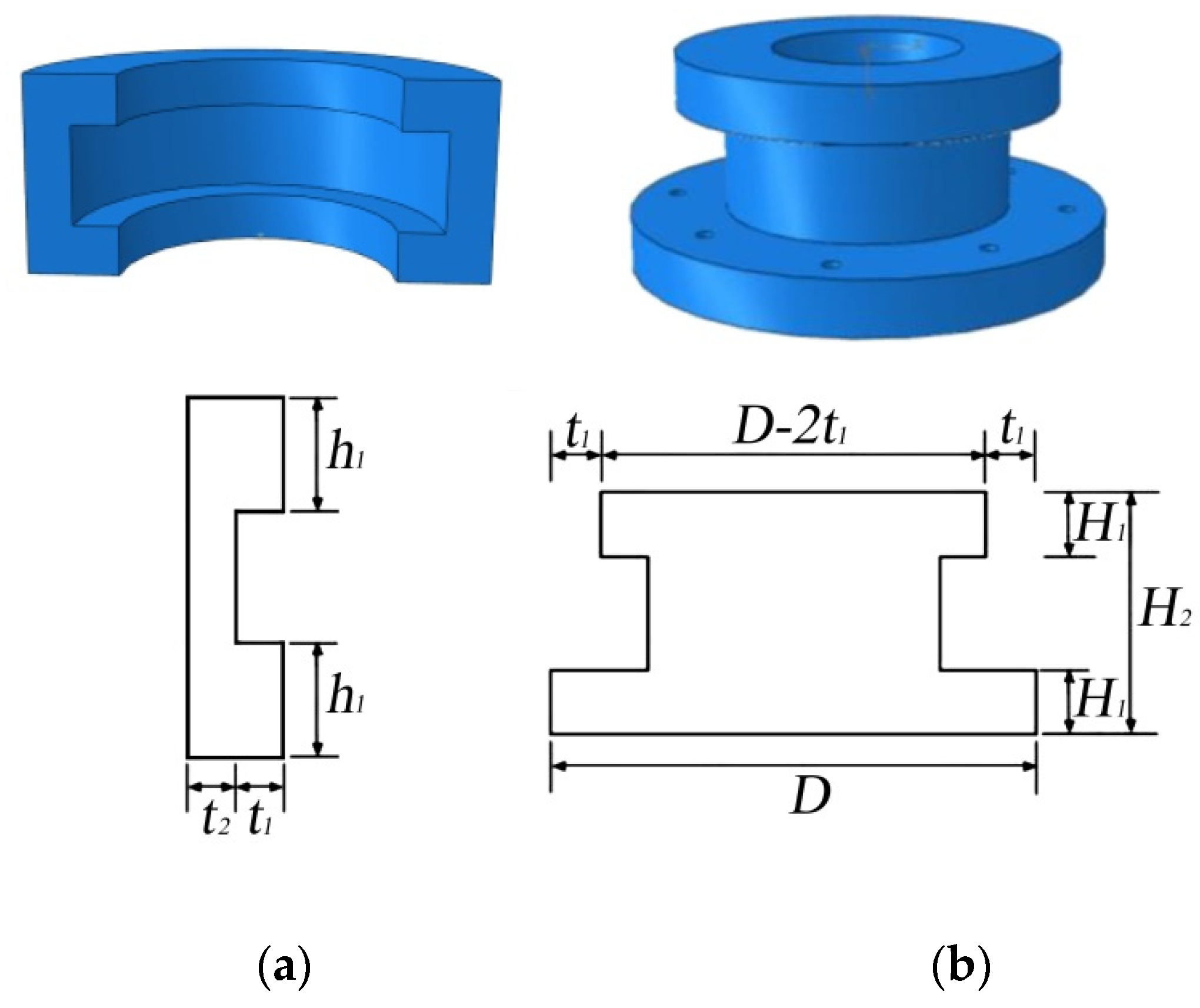
The PHC pipe pile joint flexural specimen comprises two 3 m long piles connected in the center wherein the pile joint is connected by a new type of hoop. The joint is made with two semicircular clamps with the same outer diameter as the pile body connecting the two end plates of the upper and lower pile body, as shown in Figure 1. For the new clamp, h1 is the thickness of the flange plate, h2 is the height of the web, t1 is the thickness of the web, and t2 is the outreach length of the flange plate, as shown in Figure 2a, where the width of the clamp web t1 is equal to half of the difference between the pile outer diameter and the end plate diameter. The diameter of one end of the end plate is the outer diameter of the pile, D, the diameter of the other end is D − 2t1, the thickness H1 at each end of the end plate is 1/2 × h2, the diameter of the middle cylindrical part is D − 2(t1 + t2), and the height is h1, as shown in Figure 2b.

2.2. Determining the Size of the New Joint

According to the given dimensions of the pile type [36,37], the bearing requirements are verified before determining the size of the new clamping joints. The height h2 of the web is determined according to the shear bearing capacity requirements. The outer diameter of the pile is set to D, the tensile force is N1, and the shear strength design value of the clamp is τ′; then, the height h2 of the web should satisfy Equation (1).
N 1 τ π h 2 [ D 2 ( t 1 + t 2 ) ] 2
where h2 is the height of the web, t1 is the thickness of the web, and t2 is the flange plate extension length, which is set to 20 mm.
The thickness t1 of the web is determined according to the tensile bearing requirements which needs to meet the following formula:
N 1 f t u π [ D 2 ( t 1 + t 2 ) ] 2 4
where f t u is the design value of the steel tensile strength of the clamp.
The thickness h1 of the flange plate is determined according to the shear bearing requirements and should satisfy Equation (3):
N 1 τ π h 1 ( D 2 t 1 ) 2
where h1 is the thickness of the flange plate.

3. Test Scheme

3.1. Experimental Setup

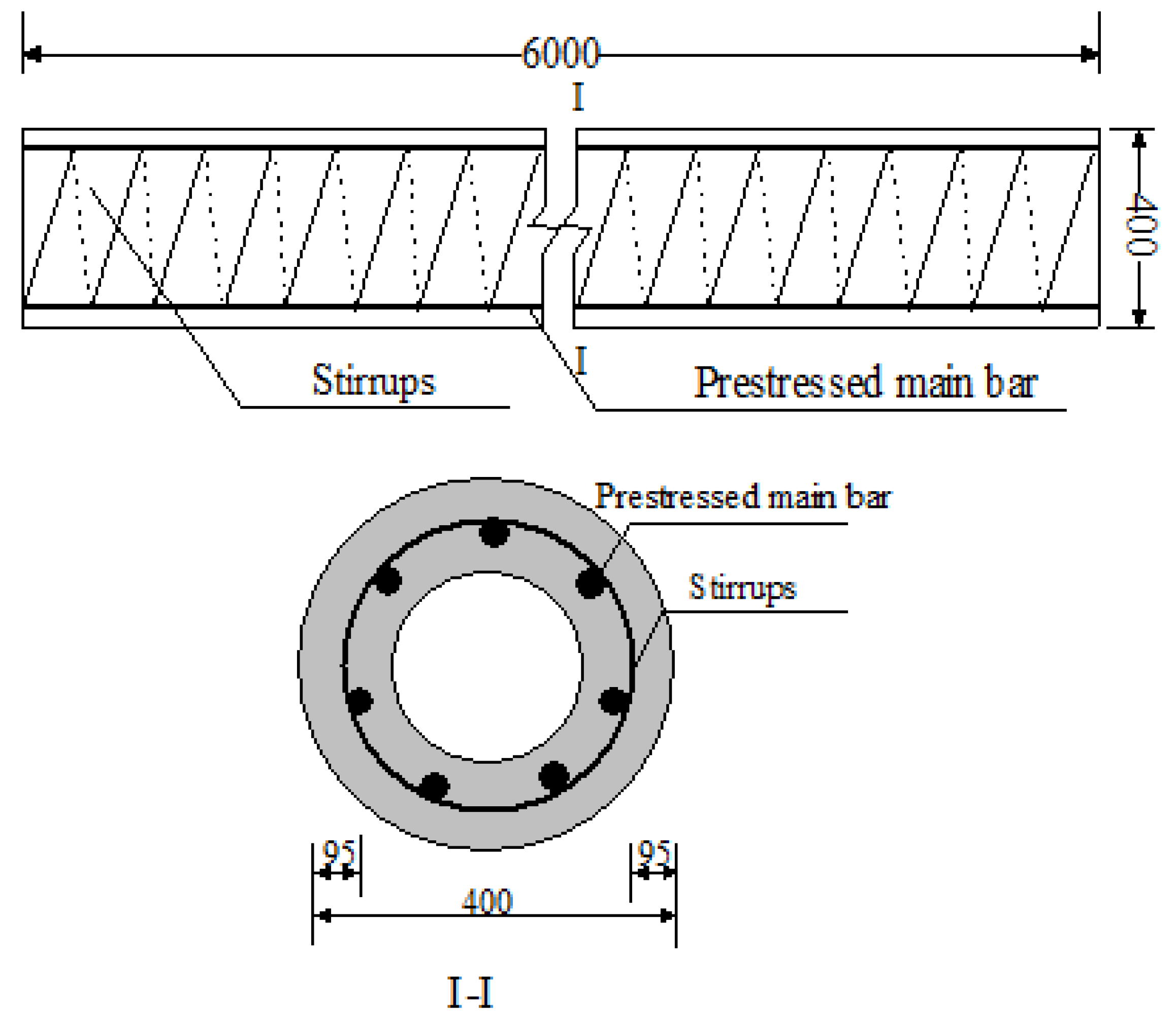
The concrete strength grade of the PHC pipe pile is C80; the main reinforcement is prestressed steel Q355; and the hoop reinforcement is steel strand. The specimen comprises two 3 m-long PHC pipe piles connected by a new type of joint, resulting in a total length of 6 m; furthermore, it is made by the centrifuging of pre-tensioning and high-pressure steam maintenance. Table 1 and Figure 3 show the detailed parameters of the PHC pipe pile specimen and the schematic diagram of reinforcement.
The hoop size of the new clamping joint of the PHC pipe pile specimen is assumed by the pile type and pile diameter; Equations (1)–(3) are used to ensure that it satisfies the bearing capacity requirements. The calculation results are as follows: the thickness of the clamp flange plate = 30 mm, height of web plate = 40 mm, thickness of web plate = 10 mm, and outreach length of flange = 20 mm. The diameter of one end of the end plate is 400 mm (500 mm), as the diameter of the other end is 380 mm (480 mm), and the thickness of each end of the end plate is 20 mm as the diameter of the middle cylindrical part is 340 mm (440 mm), and the height is 30 mm.

3.2. Load Scheme

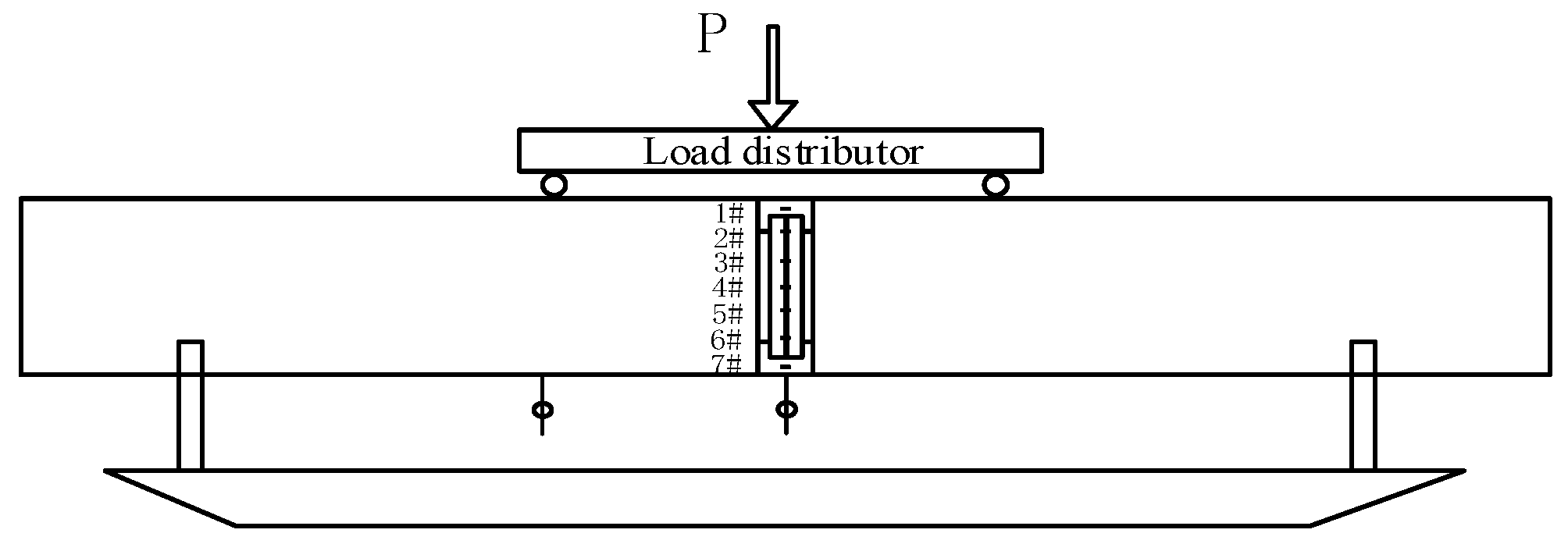
The specimens comprise two PHC pipe piles, each of four types, labelled A–D. The specimens are loaded at two points in the third part of the span, with the distance between the two supports = 4.4 m and the distance between the two loading points = 2 m. The loading is carried out by hydraulic jacks, and the symmetrical load is transferred to the specimens by the distribution steel beam, with a pure bending section between the two loading points. The test results of the same type of pipe pile are taken as the average value. A live map of the loading process is shown in Figure 4, and the specific loading scheme is as follows.
(1)
First, according to the finite element simulation results, the ultimate flexural bearing capacity of the prestressed concrete pile is predicted. The loading process adopts monotonic graded loading with a consistent loading time interval of 2–3 min.
(2)
Before loading, 10% of the estimated ultimate load is applied to the specimen to preload the test apparatus and to eliminate the gap between the device and the specimen.
(3)
The load at each level of formal loading is 5% of the predicted ultimate load, which is loaded at a uniform speed, and the next level of loading is carried out after the deformation stabilizes.
(4)
When the oil pump readings show a significant retracement and the deformation continues to increase, the specimen is considered to be damaged and reaches the limit state.
To measure the strain of the joint and the deflection of the pure bending section [38,39], strain gauges are arranged at the joint, and displacement gauges are arranged at the span and loading point. Strain gauges #1–#7 are arranged along the pile cross-section from top to bottom, as shown in Figure 5. The type of strain gauge is BSF120-80AA.

4. Test Phenomenon

When the bending moment of the pure bending section reaches 96 kN·m, a vertical crack appears on the left and right sides of the joint of specimen A. The width and length of cracks at the time of damage are 0.46 mm and 270 mm, respectively. The cracks are mainly distributed in the pure bending section at the time of damage. There are eight relatively obvious cracks, and their crack patterns are shown in Figure 6.
When the bending moment of the pure bending section reaches 99 kN·m, a vertical crack appears on the left and right sides of the joint of specimen B. The width and length of the cracks are 0.64 mm and 240 mm, respectively, at the time of damage. The cracks at the time of damage are mainly distributed in the pure bending section; there are six relatively obvious cracks whose crack patterns are shown in Figure 7.
When the bending moment of the pure bending section reaches 180 kN·m, a vertical crack appears on the left and right sides of the joint of specimen C. The width and length of the cracks at the time of damage are 0.73 mm and 290 mm, respectively. The cracks at the time of damage are mainly distributed in the pure bending section; there are six relatively obvious cracks, and their crack patterns are shown in Figure 8.
When the bending moment of the pure bending section reaches 210 kN·m, a vertical crack appears on the left and right sides of the joint of specimen D. The width and length of the cracks at the time of damage are 0.53 mm and 280 mm, respectively. The cracks at the time of damage are mainly distributed in the pure bending section; there are six relatively obvious cracks, and their crack patterns are shown in Figure 9.
As can be seen from the crack patterns of the four specimens A–D, the cracks are mainly distributed in the pure bending section under the three-point load, the cracks are approximately symmetrically distributed along both sides of the joint, and the pile body is damaged by cracks. Cracking and damage in the joint are not obvious.

5. Test Results

5.1. Strain Analysis

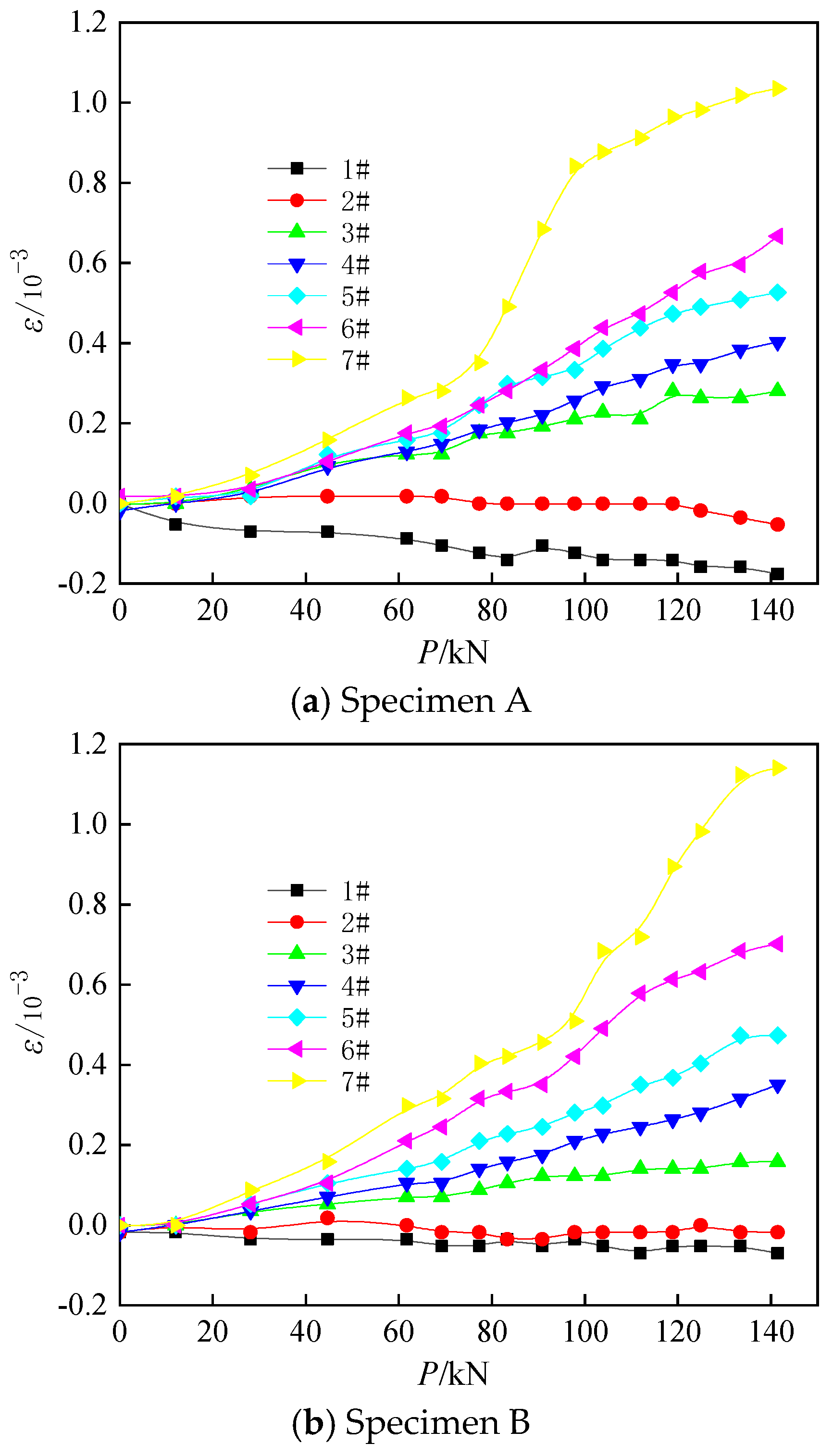
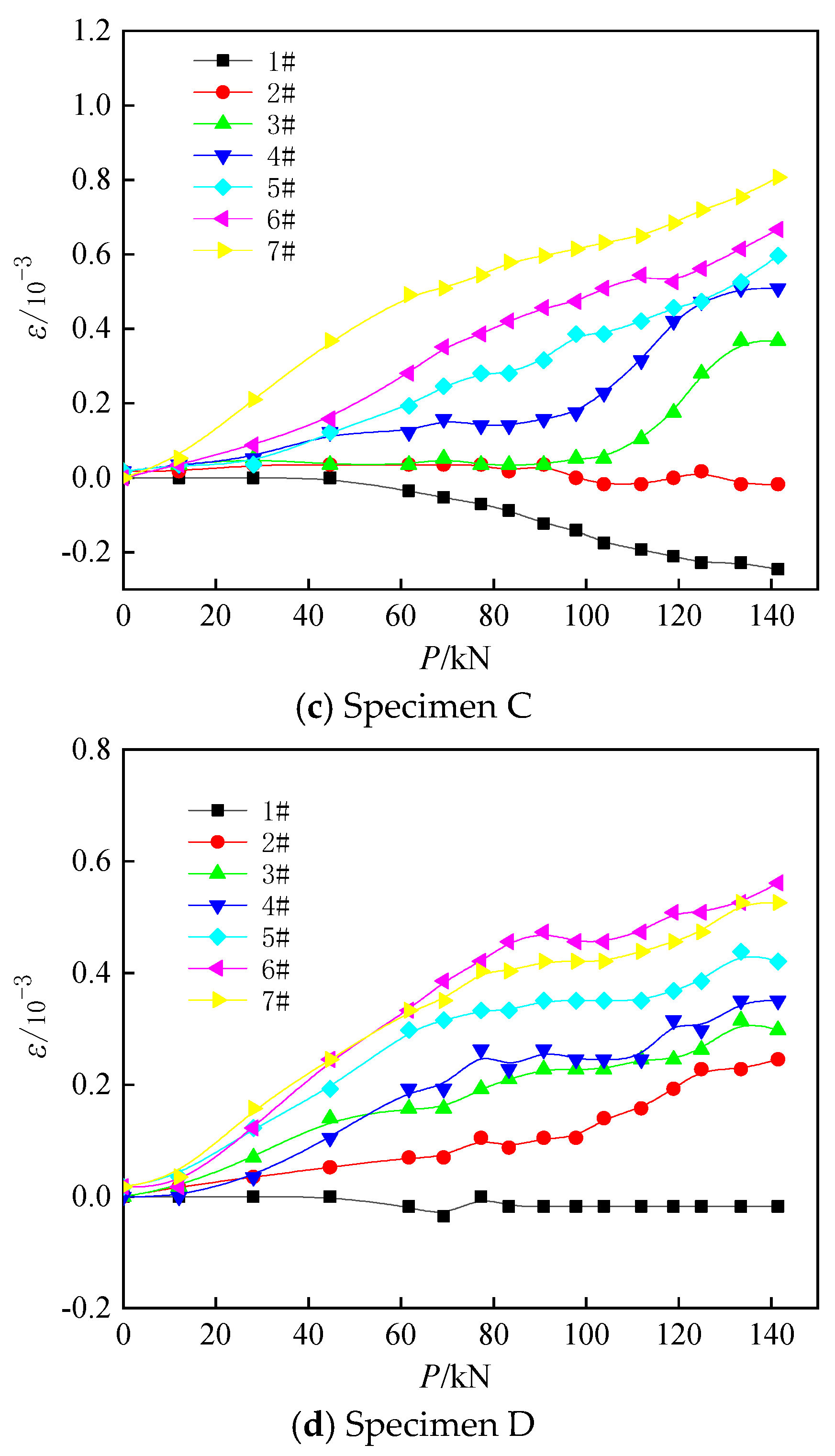
Two sets of three-point loading tests were conducted for each of the four specimens A–D. The test data were taken as the average of the test results of the same specimens between two groups. Figure 10 shows the distribution of clamp strains of the four specimens A–D. The strain is considered to be distorted when the tensile strain of the joint reaches 2.0 × 10⁻³ (Figure 10), and the distorted strain data are no longer provided. Figure 10a shows the distribution law of strain in the clamp joint as the load increases in specimen A; strain gauge position #1 is under compression, strain gauge position #2 has almost zero strain, and strain gauge positions #3–#7 are under tension. Figure 10b shows that strain gauge positions #1 and #2 are under compression, and strain gauge positions #3–#7 are under tension. Figure 10c shows that strain gauge positions #1 and #2 are under compression, strain gauge positions #3–#7 are under tension, and the magnitude of the strain increases from top to bottom. Figure 10d shows that strain gauge position #1 is under compression and the compression strain is small; strain gauge positions #2–#7 are under tension; and the magnitude of the strain increases from top to bottom. As the load increases, the values of tensile strain and compression strain increase.

5.2. Flexural Capacity

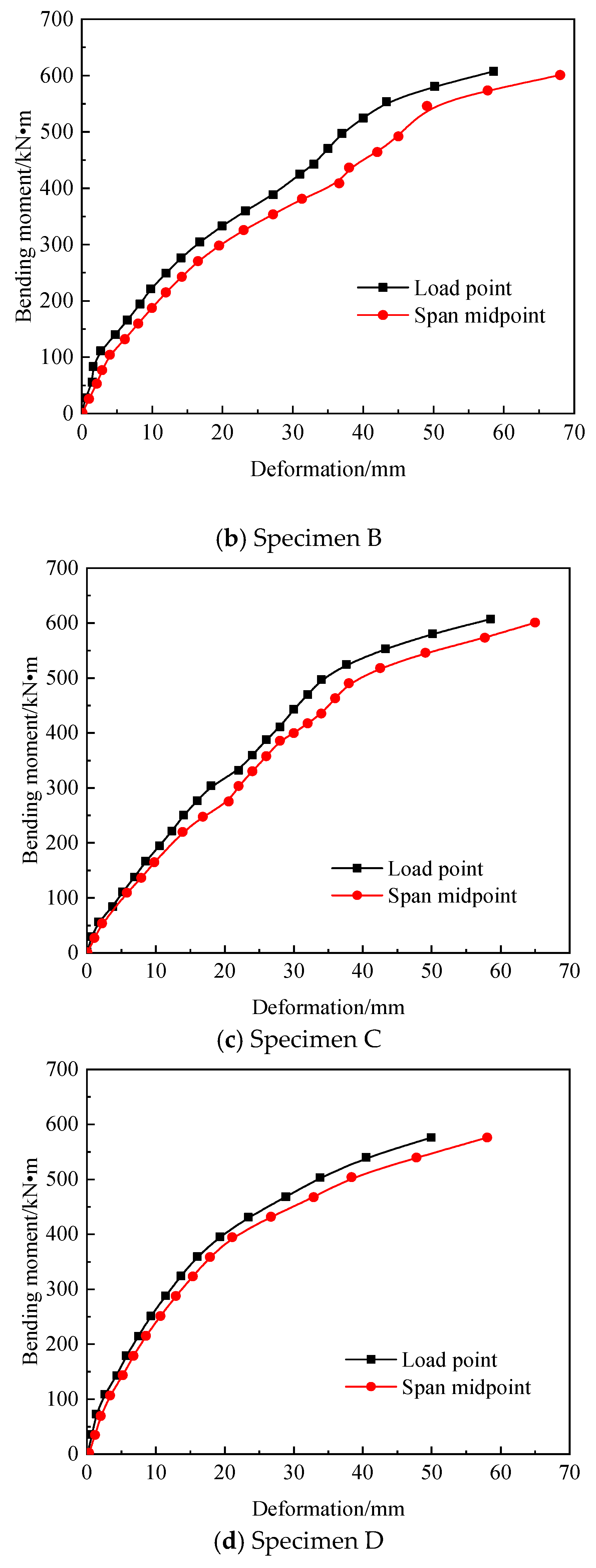
Figure 11 shows the bending moment distribution of the pure bending section of specimens A–D. When the bending moment is small, the mid-span deflection of all specimens is almost the same as the loading point; under the action of the same bending moment, the mid-span deflection of all specimens is larger than the deflection of the loading point.

6. Comparison with FEM

Finite element simulations were performed for class A PHC pipe piles under monotonic graded loads; for the PHC pipe piles, the outer diameter is 400 mm, wall thickness is 95 mm, the main reinforcement material is 7A10.7, and the stirrup is Ab5@80. The loading scheme used for the finite element simulations is the same as that of the test.

6.1. Material Constitutive Model and Parameters

The finite element analysis software ABAQUS is used to numerically simulate piles under three-point loads. The concrete model is established using the stress–strain relationship provided by Guo [4]. The concrete strengths are defined in the simulations according to the experimental values, and the standard value of axial compressive strength of C80 concrete is 50.2 MPa. The tensile and compressive damage parameters for concrete are calculated using Equations (4) and (5).
σ c = ( 1 d c ) E c ε
σ t = ( 1 d t ) E c ε
where dc and dt are the uniaxial compressive and uniaxial tensile damage evolution parameters of concrete, respectively, and Ec is the elastic modulus of concrete, which is taken as 3.8 × 10⁴ N/mm2.
The isotropic elastic–plastic model provided by ABAQUS software was used for the main reinforcement and joint to satisfy the Von Mises yield criterion, which can simulate the elastic–plastic properties of steel bars. The elastic modulus and Poisson’s ratios are 2.1 × 10⁵ MPa and 0.3, respectively, and the expressions for the stress–strain relationship are given in Equation (6):
σ = { E s ε σ f y f y + 0.1 ( ε ε y ) σ > f y
The concrete and steel bar material performance parameters are shown in Table 2.

6.2. Contact Relation and Loading Method of Element Type

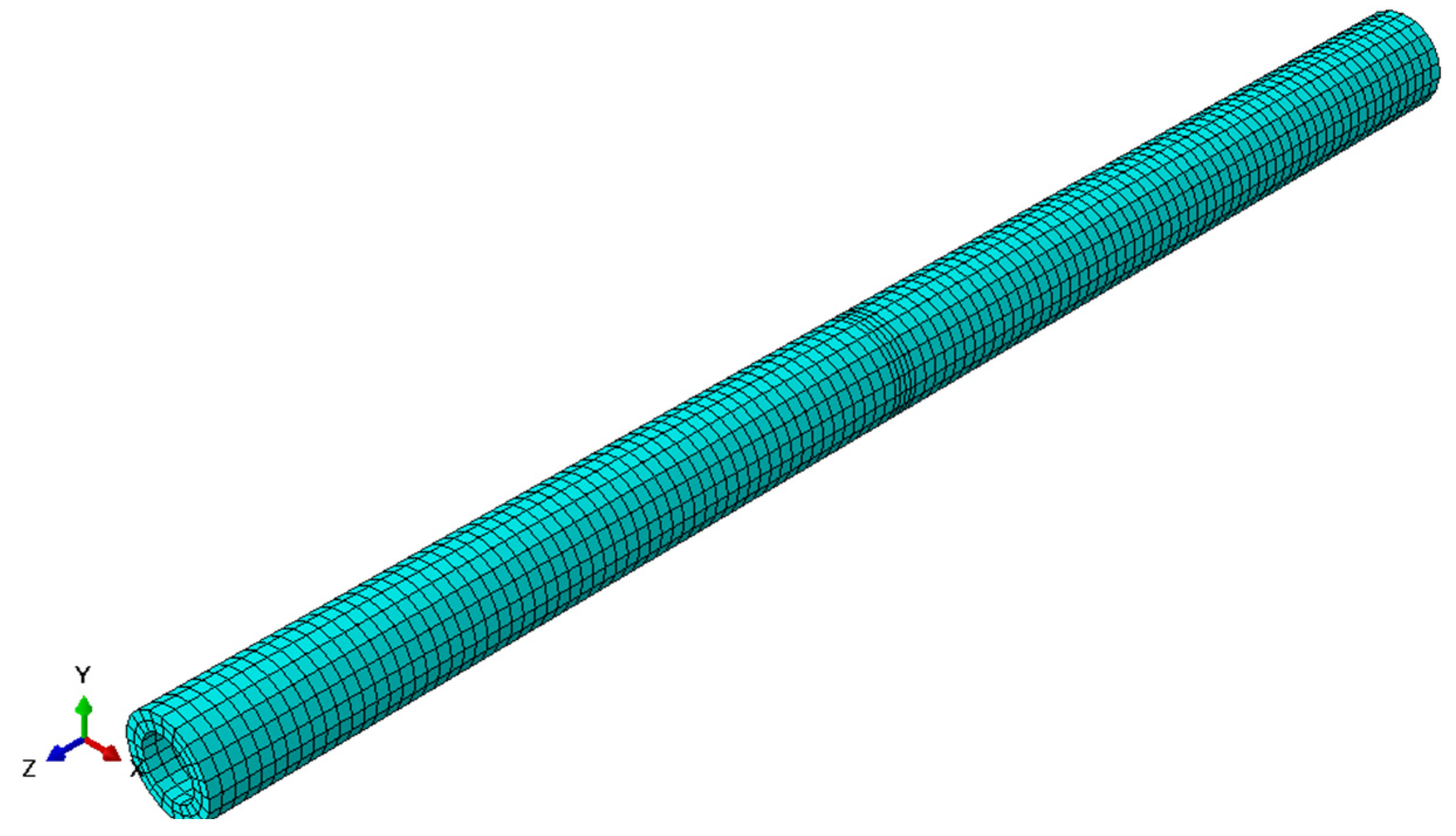
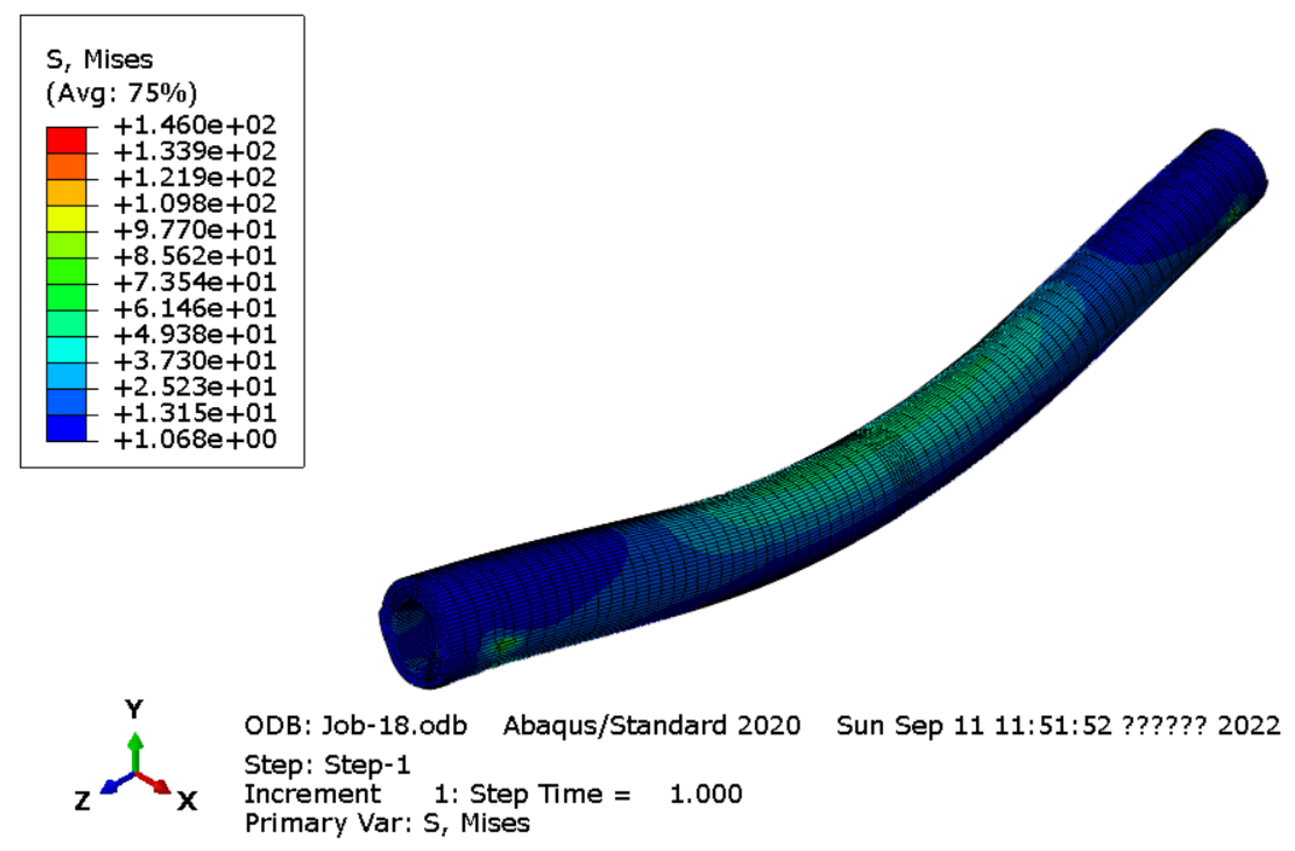
The C3D8R unit is used for pile concrete and clamps, and the T3D2 truss unit is used for prestressed reinforcement and stirrups. In the finite element model, binding constraints are used between the bracket, the curved clamps and the pile concrete, and the concrete and the joint are also bound. The two surfaces in the model are tightly bound together and do not separate during the analysis. The prestressed reinforcement and stirrups are embedded in the concrete according to the embedding zone. The loading process includes the following three stages: the initial stage, prestressing the PHC pipe pile, and application of the pure bending load. The boundary constraints of the model are mainly concentrated on the two supports. Considering that both ends of the pile are loaded during the test, the boundary conditions define one side of the central axis to support U1 = U2 = UR3 = 0, which not only ensures the existence of vertical displacement but also limits the torsional deformation of the pile. The division of the finite element mesh is shown in Figure 12, the mesh at the joint is encrypted, and the cloud of finite element results is shown in Figure 13.

6.3. Comparison of Numerical Values and Test Results

The bending moment–deflection curves comparing the finite element and test results under the three-point load are shown in Figure 14.
As shown in Figure 14, the bending moment-displacement curves obtained from the ABAQUS analysis are consistent with those obtained from the test results. The curves obtained from the finite element analysis lie below the test curves; this is attributed to the fact that, during the test, the member accumulates some damage under the three-point load, which decreases the stiffness. However, the accumulated damage in the concrete is not taken into account during the simulation. The concrete in the compression zone does not crush during the test, and it is mainly controlled by the prestressing tendon for the strength of the members. The cracks influence the stiffness and only slightly influence the bearing capacity. Therefore, the ultimate bearing capacity obtained from the simulation and experiments is almost the same.

7. Conclusions

In this study, a new type of joint is proposed and tested using bending resistance tests and simulation analyses. The flexural performance of the new joints of different types of piles is explored through test phenomena, the development of strain, and the changing law of flexural bearing capacity. The following conclusions are obtained:
(1)
By observing the crack pattern of the stirrup joint specimens, we determined that cracks are mainly distributed in the pure bending section under pure bending load. Due to the high bearing capacity of the joint, the pile body first develops cracks and fails with an increase in load.
(2)
By analyzing the distribution law of the joint strain of the specimen, we found that it is mainly subject to tension under the action of a pure bending load. With an increase in load, the values of tensile and compressive strains increase.
(3)
By analyzing the bending moment distribution of the pure bending section of the specimen, it can be determined that when the bending moment is small, the mid-span deflection of all specimens is basically the same as the loading point; however, as the bending moment increases, under the same bending moment, all the specimens span medium deflection, which is greater than the deflection at the loading point.

Author Contributions

Theoretical analysis, experiment, validation, and writing, B.W.; writing and translation, L.Q.; check, Y.Y. All authors have read and agreed to the published version of the manuscript.

Funding

The work described in this paper was supported by the Gansu Province Qingyang City Scientific Support Funds (Grant No. QY2021A-F028).

Institutional Review Board Statement

Not applicable.

Informed Consent Statement

Not applicable.

Data Availability Statement

The data supporting the results reported in the paper can be requested from the corresponding authors.

Acknowledgments

The findings and opinions expressed in this article are only those of the authors and do not necessarily reflect the views of the sponsors.

Conflicts of Interest

No conflict of interest to declare.

References

  1. Shi, F. Experimental research on load transfer mechanism of pretensioned high strength spun concrete piles. Chin. J. Geotech. Eng. 2004, 26, 95–99. [Google Scholar]
  2. Lv, W.T.; Wang, Y.H.; Leng, W.M. Testing and numerical analysis of load transfer mechanism of PHC pile. Rock Soil Mech. 2006, 27, 466–470. [Google Scholar]
  3. Ruan, X. Experimental Research on Bearing Behavior of Jacked PHC Pipe Piles. J. Kunming Univ. Sci. Technol. 2011, 36, 33. [Google Scholar]
  4. Guo, Y.; Cui, W. Experimental study on application of PHC piles in paleo-clay area. Chin. J. Geotech. Eng. 2011, 33, 108–115. [Google Scholar]
  5. Kang, J.W.; Zang, S.Z.; Gan, Y. Vertical bearing capacity of driven PHC piles in the Chengdu gravel foundation. Chin. J. Geotech. Eng. 2010, 32, 107–110. [Google Scholar]
  6. Zong, Z.L. Study on Load Transfer Mechanism of PHC Piles under the Silting Geological Condition. Build. Sci. 2011, 27, 22–24. [Google Scholar]
  7. Liu, F.; Zheng, J.G. Immersion tests on PHC piles in collapsible loess. Chin. J. Geotech. Eng. 2011, 33, 362–366. [Google Scholar]
  8. Liu, Z.H.; Zheng, J.G.; Yu, Y.T. Vertical bearing behaviors of PHC piles in collapsible loess. Chin. J. Geotech. Eng. 2010, 32, 111–114. [Google Scholar]
  9. Chen, Z.S.; Rui, R.; Xia, Y.Y. Analysis of Pile-Soil Relative Displacements of Soft Soil Roadbed Reinforced by Prestressed Tubular Piles. Highway 2005, 8, 280–284. [Google Scholar]
  10. Shen, Y.P.; Mao, Y.F.; Jing, P.; Cheng, W.H. Experimental effect contrast between PHC and CFG pile-raft composite foundation in high speed railway base treatment. Chin. J. Rock Mech. Eng. 2014, 33, 4174–4180. [Google Scholar]
  11. Cao, X.; Dai, G.; Gong, W.; Tang, J. Experimental study on the seismic behavior of new PHC piles. Arab. J. Geosci. 2020, 13, 778. [Google Scholar] [CrossRef]
  12. Cao, X.; Dai, G.; Gong, W.; Zhou, F.; Xu, J. Resistance of saturated soil to a laterally vibrating pile. Soil Dyn. Earthq. Eng. 2020, 141, 106496. [Google Scholar]
  13. Cao, X.; Wang, S.; Gong, W.; Wu, W.; Dai, G.; Zhou, F. Experimental and theoretical study on dynamic stiffness of floating single pile and pile groups in multi-layered soil. Soil Dyn. Earthq. Eng. 2022, 157, 107282. [Google Scholar] [CrossRef]
  14. Yang, Z.J.; Li, G.C.; Wang, W.J.; Lv, Y.J. Study on the flexural performance of prestressed high strength concrete pile. KSCE J. Civ. Eng. 2018, 22, 4073–4082. [Google Scholar] [CrossRef]
  15. Banerjee, S.; Stanton, J.F.; Hawkins, N.M. Seismic performance of precast prestressed concrete piles. J. Struct. Eng. 1987, 113, 381–396. [Google Scholar] [CrossRef]
  16. Wang, T.C.; Yang, Z.J.; Zhao, H.L.; Wang, W.J. Seismic performance of prestressed high strength concrete piles. Mater. Res. Innov. 2014, 18, 515–521. [Google Scholar] [CrossRef]
  17. Au, F.T.K.; Leung, C.C.Y.; Kwan, A.K.H. Flexural ductility and deformability of reinforced and prestressed concrete sections. Comput. Concr. 2011, 8, 473–489. [Google Scholar] [CrossRef]
  18. Wang, Y.F.; Chen, G.; Xu, Q.B.; Gong, S.F.; Xiao, Z.B.; Fan, H. Study on Tensile Behavior of Prestressed Concrete Square Pile Connection Joint with Resilient Clamping. J. Disaster Prev. Mitig. Eng. 2018, 38, 1003–1011. [Google Scholar]
  19. Lu, L.H.; Han, S.; Chen, Z.X.; Wang, G. Study on bending performance of prefabricated square pile with socket and spigot joint. J. Build. Struct. 2018, 39, 153–161. [Google Scholar]
  20. Zhu, B.; Zhang, F.W.; Zhu, H.S. Wear resistance test on steel joint anticorrosion coating for precast square piles. Eng. J. Wuhan Univ. 2017, S1, 299–302. [Google Scholar]
  21. Dai, X.F. A New Type of Mechanical Connection Joint of Pre-Stressed Concrete Pipe Pile. Ph.D. Thesis, Zhejiang University of Technology, Hangzhou, China, 2015. [Google Scholar]
  22. Xu, Q.B.; Chen, G.; He, J.F.; Gong, S.F. Flexural performance experiment of connection joint for composite reinforcement concrete prefabricated square piles. J. Zhejiang Univ. 2017, 51, 1300–1308. [Google Scholar]
  23. Chen, J.S.; Mo, H.H. Three-dimensional FEM Analysis on Flexural Rigidity of Segment Joints in Shield Tunnel. J. China Railw. Soc. 2009, 31, 87–91. [Google Scholar]
  24. Zeng, D.Y.; He, C. Numerical Simulation of Segment Joint Bending Stiffness of Metro Shield Tunnel. J. Southwest Jiaotong Univ. 2004, 6, 744–748. [Google Scholar]
  25. Song, K.Z.; Yuan, D.J.; Wang, M.S. Dynamic performance detection of CFRP composite pipes based on quasi-distributed optical fiber sensing techniques. Rock Soil Mech. 2008, 29, 619–623. [Google Scholar]
  26. He, C.; Zhang, J.G.; Yang, Z. Model test study on the mechanical characteristics of segment lining for the Wuhan Yangtze River tunnel. China Civ. Eng. J. 2008, 12, 85–90. [Google Scholar]
  27. Li, Z.P.; Wang, C.; Su, H.F.; Shi, S. Mechanical Property of Tenon-Groove Joints for Metro Station Constructed by Prefabricated Structure. China Railw. Sci. 2015, 36, 7–11. [Google Scholar]
  28. Liu, J.H. Study on the Design Optimization of the Fabricated Structure of the Subway Station of the Constructed by Open-Cut Method and the Mechanical Behavior of Construction. Ph.D. Thesis, Southwest Jiaotong University, Chengdu, China, 2007. [Google Scholar]
  29. Guner, S.; Chiluwal, S. Cyclic load behavior of helical pile-to-pile cap connections subjected to uplift loads. Eng. Struct. 2021, 243, 112667. [Google Scholar] [CrossRef]
  30. Xu, Y.; Zeng, Z.; Wang, Z.; Ge, J. Experimental studies of embedment length of precast bridge pier with socket connection to pile cap. Eng. Struct. 2021, 233, 111906. [Google Scholar] [CrossRef]
  31. Yang, Z.; Wang, W. Experimental and numerical investigation on the behaviour of prestressed high strength concrete pile-to-pile cap connections. KSCE J. Civ. Eng. 2016, 20, 1903–1912. [Google Scholar] [CrossRef]
  32. Wang, T.; Yang, Z.; Zhao, H.; Wang, W. Seismic Performance of Prestressed High Strength Concrete Pile to Pile Cap Connections. Adv. Struct. Eng. 2014, 17, 1329–1342. [Google Scholar] [CrossRef]
  33. Joen, P.H. Seismic Performance of Prestressed Concrete Piles and Pile-Pile Cap Connections. Ph.D. Thesis, University of Canterbury, Christchurch, New Zealand, 1987. [Google Scholar]
  34. Chiluwal, S.; Guner, S. Helical Pile-to-Pile Cap Connections Subjected to Uplift Forces: Improving Future Practice. In Proceedings of the Deep Foundations Institute 44th Annual Conference, Chicago, IL, USA, 15–18 October 2019. [Google Scholar]
  35. Guo, Z.; He, W.; Bai, X.; Chen, Y.F. Seismic Performance of Pile-Cap Connections of Prestressed High-Strength Concrete Pile with Different Details. Struct. Eng. Int. 2017, 27, 546–557. [Google Scholar] [CrossRef]
  36. Wang, H.; Chen, H.; Chen, C.; Zhao, H.; Jiang, H.; Song, T.; Feng, S. The Structural Performance of CFRP Composite Plates Assembled with Fiber Bragg Grating Sensors. Symmetry 2021, 13, 1631. [Google Scholar] [CrossRef]
  37. Wang, H.; Song, T.; Yan, J.; Xiang, P.; Feng, S.; Hui, D. Improved analytical method for interfacial-slip control design of steel-concrete composite structures. Symmetry 2021, 13, 1225. [Google Scholar] [CrossRef]
  38. Wang, H.; Jiang, L.; Xiang, P. Improving the durability of the optical fiber sensor based on strain transfer analysis. Opt. Fiber Technol. 2018, 42, 97–104. [Google Scholar] [CrossRef]
  39. Sasy, C.; Yung, W.; Hua-Ping, W.; Ping, X. Optical Fiber Sensors for Monitoring Railway Infrastructures: A Review towards Smart Concept. Symmetry 2021, 13, 2251. [Google Scholar] [CrossRef]
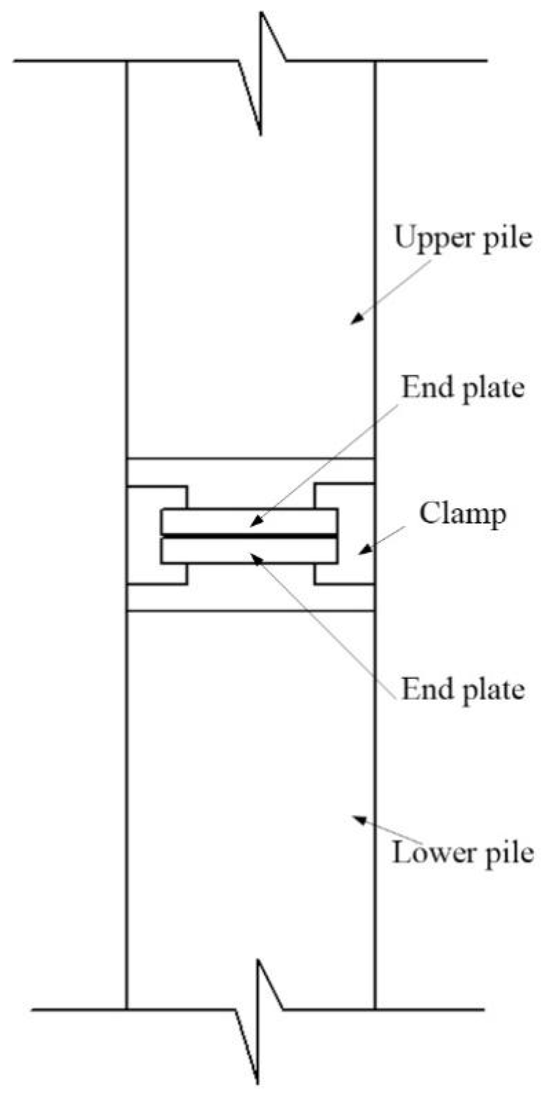
Figure 1. Schematic diagram of PHC pipe pile hoop connection.
Symmetry 14 01920 g001
Figure 2. Schematic diagram of the new joint clamps and end plates: (a) hoop; (b) end plate.
Symmetry 14 01920 g002
Figure 3. Schematic diagram of the reinforcement of PHC pipe pile (pile diameter = 400 mm) (all units are in millimeters).
Symmetry 14 01920 g003
Figure 4. Loading live map.
Symmetry 14 01920 g004
Figure 5. Schematic diagram of loading device.
Symmetry 14 01920 g005
Figure 6. Crack pattern of specimen A.
Symmetry 14 01920 g006
Figure 7. Crack pattern of specimen B.
Symmetry 14 01920 g007
Figure 8. Crack pattern of specimen C.
Symmetry 14 01920 g008
Figure 9. Crack pattern of specimen D.
Symmetry 14 01920 g009
Figure 10. Strain distribution law of clamp joint.
Symmetry 14 01920 g010aSymmetry 14 01920 g010b
Figure 11. Distribution law of bending moment in pure bending section.
Symmetry 14 01920 g011aSymmetry 14 01920 g011b
Figure 12. Finite element mesh of pile body and new joint.
Symmetry 14 01920 g012
Figure 13. Finite element results cloud.
Symmetry 14 01920 g013
Figure 14. Comparison of finite element and test results.
Symmetry 14 01920 g014
Table 1. Detailed parameters of the specimen.
NumberPile TypePile Diameter
(mm)
Wall
Thickness (mm)
Prestressed Main
Reinforcement
Hoop Reinforcementσc
(MPa)
AAB400957A10.7Ab5@806.48
BAB4001007A10.7Ab5@806.48
CAB500957A10.7Ab5@806.48
DAB5001007A10.7Ab5@806.48
Table 2. Concrete and steel bar material performance parameters.
Model MaterialVolumetric Weight (kN/m3)Tensile Modulus (GPa)Yield Strength (MPa)Compressive Strength (MPa)Poisson’s
Ratio
Steel bar78.5206335-0.23
Concrete2538-800.20
Publisher’s Note: MDPI stays neutral with regard to jurisdictional claims in published maps and institutional affiliations.