Article

Numerical Simulation on Heat Transfer Augmentation by Using Innovative Hybrid Ribs in a Forward-Facing Contracting Channel

1
Department of Biomedical Engineering, College of Engineering, University of Thi-Qar, Nasiriyah 64001, Iraq
2
Energy and Mechanical Engineering Laboratory (LEMI), University of Boumerdes, Boumerdes 35000, Algeria
3
Department of Physics, College of Education, University of Garmian, Kalar 46021, Iraq
4
Air Conditioning and Refrigeration Techniques Engineering Department, Al-Mustaqbal University College, Babylon 51001, Iraq
5
Ministry of Higher Education & Scientific Research, Department of Studies, Planning & Follow-Up, Baghdad 10011, Iraq
6
Electromechanical Engineering Department, University of Technology, Baghdad 10066, Iraq
7
Department of Oil and Gas Engineering, Basrah University for Oil and Gas, Basra 61004, Iraq
8
Department of Mechanical Engineering, University of Kufa Najaf, Kufa 54003, Iraq
9
Scientific Research Center, Al-Ayen University, Nasiriyah 64001, Iraq
10
Department of Petroleum & Gas Engineering, College of Engineering, University of Thi-Qar, Nasiriyah 64001, Iraq
*
Author to whom correspondence should be addressed.
Symmetry 2023, 15(3), 690; https://doi.org/10.3390/sym15030690
Submission received: 14 February 2023 / Revised: 26 February 2023 / Accepted: 6 March 2023 / Published: 9 March 2023
(This article belongs to the Special Issue Advances in Heat and Mass Transfer with Symmetry)

Abstract

:
This study aims to investigate the thermal behavior and aerodynamic phenomena in a heated channel with varied rib configurations using computational fluid dynamics (CFD) simulations. Incorporating ribs in such systems enhances heat transfer and increases flow resistance and manufacturing costs. Understanding heat exchanger theory, measurement methods, and numerical calculations are crucial for creating efficient heat exchangers. The current research employs numerical analysis to assess the impact of hybrid ribs on heat transfer enhancement in forward-facing contracting channels (FFS). A two-dimensional forced convection heat transfer simulation under turbulent flow conditions was performed, considering the presence and absence of ribs with dimensions of 1 cm by 1 cm and spaced 11 cm apart. The arrangement of the ribs causes symmetrical temperature and flow distribution after and before each rib. The results demonstrate that the use of hybrid ribs outperforms the use of individual rib configurations in terms of thermal performance. This is due to the distinct flow patterns generated as the fluid passes through each rib. The triangle ribs had a more significant impact on the pressure drop than other rib configurations, while the cross ribs showed a lesser effect. The ribs improve the heat transfer coefficient while increasing the pressure drop, and the values of the Reynolds number were found to be directly proportional to the heat transfer coefficient and the pressure drop. The study concludes with a qualitative and quantitative analysis demonstrating the accuracy and coherence of the obtained computational results.

1. Introduction

Heat transfer enhancement technology is crucial in cooling and thermal systems as every heat exchanger presents an opportunity for improvement. There have been numerous advancements in heat transfer enhancement technologies to reduce the size, enhance thermodynamic process efficiency, and save costs in different engineering applications. Many computational and experimental studies have focused on exploring changes in transport pipelines that impact thermal performance, including ribbed channels, expanding, or contracting passages, and the utilization of fins.
Effect of the rib height on the pressure drop and local heat transfer distribution in a square channel with 90° continuous and 60° V-broken ribs studied by SriHarsha et al. [1]. The increase in the rib height to hydraulic diameter ratio (e/D) is seen to enhance heat transfer enhancements in the channel with 90° continuous attached ribs; however, at the loss of pressure drop all over the test rig.
A numerical study is done by Hussein et al. [2] on the turbulence of heat transmission and hybrid Al2O3-Cu-nanofluid across a vertical double forward-facing step. The major conclusions showed that local heat transfer coefficients increased as the Reynolds number increased, reaching their maximum value at Re = 40,000. Moreover, increases in heat transfer coefficient were observed with hybrid (Al2O3-Cu-water) nanofluid volume concentrations, with the maximum heat transfer coefficient recorded at hybrid Al2O3-Cu-water nanofluid of 2% in comparison to others.
Promyooge [3] present an evaluation of the turbulent forced convection heat transfer and friction loss characteristics for airflow through a channel with several 60° V-baffle turbulators. The study findings show that the V-baffle significantly improves flow mixing compared to a smooth wall channel by increasing the Nusselt number, friction factor, and thermal improvement factor values through the induction of secondary flows caused by vortex flows produced by the V-baffle.
Hussein et al. [4] conducted an experimental analysis to examine the impact of step height on the heat transfer to radially enlarged outwards air flow in a concentric circular channel. The findings indicate that as the heat flux and Reynolds number rise, similarly do the values of the local heat transfer coefficient. Step variation has a noticeable impact on the heat transfer process in the separation zone as the step height increases, while it has less of an impact in the reconstruction region.
Using particle image velocimetry, Sherry et al. [5] conducted an experimental analysis of the recirculation zone created downstream of a forward-facing step submerged in a turbulent boundary layer. The set separation point for observing bluff body flow is at the step’s leading edge. A variety of Reynolds numbers (1400–19,000) are used to describe the recirculation region’s dimensions, with Reh based on the step height and free stream velocity.
Hussein et al. [6] presented an overview of experimental research on turbulent heat transfer in separation flow. They noted that the increased turbulent heat transfer rate in separation flow had been highlighted by the use of swirl generators in pipes, annular pipes, and rapid expansion in passages.
Hussein et al. [7] conducted an experimental study on the impact of step height on heat transmission to a stream of radially outward enlarged air in a concentric circular channel. Enhanced heat flux and/or Re resulted in an increase in the local heat transfer coefficient. Heat transfer in the separation region is significantly impacted by step variation, and this impact grows as step height rises, while it has less of an impact in the redevelopment region.
Gupta et al.’s [8] current research aims to quantify the local heat transfer distributions in a square channel with a double wall and ribs that are 90° continuous, 90° saw tooth profiled, and 60° V-broken. The enhancements in heat transfer in the channel with 90° saw-tooth profiled ribs are found to be comparable to those of 90° continuous ribs.
Oon et al. [9] have studied how a sudden expansion in an annular tube can cause the separation and reattachment of water flow. The surface temperature all along the channel is reduced to the lowest value by an increase in flow, which gradually rises to a peak and remains constant for the remainder of the pipe. At the flow reattachment point, the lowest surface temperature is measured.
Daniel and Hendrik [10] examine numerically the overall stability over time of the two-dimensional, incompressible flow over a forward-facing step in a planar channel. According to an energy-transfer analysis, the fundamental flow becomes unstable as a result of the interaction between lift-up and flow deceleration, which results in a critical mode with constant streaks.
Hussein et al. [11] utilized numerical analysis to examine the numerical studies of turbulent heat transfer in separation flow, improvement of the rate of heat transfer in turbulent separation flow at sudden expansion in the passage, over forward or backward facing steps, blunt body, ribs channel, and swirl generators in channels. The numerical findings showed that as the essential parameters were increased, the heat transfer coefficients increased as well. The numerical simulations included many computational programs and were generated from the finite volume, element, and different methods for evaluating turbulent heat transfer in separated flow.
Togun et al. [12] provide research on the heat transfer improvement of hybrid “Al2O3-Cu/water” nanofluids flowing in a two-dimensional channel with semicircle ribs. The simulation findings showed that the addition of ribs improved the passage’s ability to transport heat. When the solid volume fraction of “Al2O3-Cu/water” hybrid nanofluids and the Re number grew, the Nusselt number also increased.
Direct numerical simulation is used by Hattori and Nagano [13] to study the turbulent boundary layer over forward-facing steps. The findings demonstrate the turbulent quantitative statistics and boundary layer structures over a forward-facing step, with prominent counter-gradient diffusion phenomena (CDP) being particularly evident on the step that is closest to the wall.
Togun et al. [14] present a numerical study of heat transfer and laminar airflow over a double backward-facing step. The results indicate that the Nusselt number rises as the Reynolds number rises in all circumstances, with the greatest Nusselt number occurring at the first step as opposed to the second.
In their research, Scheit et al. [15] used direct numerical simulation (DNS) and the finite volume method to investigate turbulent fluid flow over a forward-facing step. They found a significant accumulation of streaklines due to recirculation flow at step 1. Biswas et al. [16] investigated the effect of backward-facing step height on fluid flow and found that the separation length increased non-linearly, in agreement with Armaly et al. [17]. Hakan [18] also studied the impact of the contraction ratio on heat transfer and found the maximum improvement occurred at a contraction ratio of one. Sano Ma-satoshi et al. [19] evaluated fluid flow through a backward-facing step channel with suction applied over a slot at the step’s end corner. They found that the separation zone had a higher heat transfer coefficient and lower pressure drop.
In computational fluid dynamics (CFD) programming, advances have led to numerous attempts to examine velocity processes and heat transfer features. Abe et al. [20,21] used RANS with a new K-ɛ model for modeling heat transfer and fluid flow at the recirculating and reattaching zone and found the results of Vogel and Eaton [22] to be very acceptable. Terekhov et al. [23] discovered that the length of the separation region behind the step decreased as the rib moved away from the edge. The one-equation model better explains this change in size than the Smagorinsky model. Zhdanov et al. [24] used the LES method with the Smagorinsky and one-equation models to study the influence of the separated flow structure on the parameters of the separation region behind a backward-facing step. The velocity field characteristics on the step edge and the development dynamics of the separation zone were poorly described by the Smagorinsky model, leading to the use of the one-equation model for calculating turbulent properties of the separation zone behind the step. Terekhova et al. [25] conducted an experimental study of heat and mass transfer behind a backward-facing step in the presence of detached vortex generators in a Reynolds number range of 5000–15,000. They found, using a deflector, that the position of heat transfer maxima could be regulated by intensifying heat transfer in the area near the ledge’s base.
In their simulation study, Fifi et al. [26] used the conventional k-w model, Shear Stress Transport (SST), and Reynolds Stress Transport (RST) to examine turbulent heat transfer and fluid flow in pipes with various rib shapes (square ribs triangular ribs, and trapezoidal ribs) and found the SST turbulence model to have the best data agreement, with trapezoidal ribs having the highest heat transfer coefficient compared to other cases. Tanda [27] investigated the effect of transverse and V-shaped ribs on turbulent heat transport at 45 and 60 degrees and found the largest improvement in heat transfer was obtained with V-ribs compared to continuous ribs. In contrast, SriHarsha et al. [1], Promvonge [3], and Gupta et al. [8] found that V-ribs had the greatest impact.
Many researchers in various applications have investigated using nanofluids as modern and effective coolants. The shear stress transport (SST) K-ɛ model was used to simulate turbulence [28]. This simulation took into account three different volume fractions of nanofluid (0%, 2%, and 4%), variable Reynolds numbers (50–200 for laminar flow and 5000–20,000 for turbulent flow), an expansion ratio of 2, and a constant heat flux of 4000 W/m2. The outcomes demonstrate how increasing the Nusselt number in the laminar and turbulent regions is impacted by the volume percentage of the nanofluid. Safeai et al. [29] examined the heat transfer caused by the turbulent forced convection of water and functionalized multi-walled carbon nanotube (FMWCNT) nanofluids over a step that faced forward. The findings show that the Reynolds number and FMWCNT volume % significantly influence the heat transfer coefficient. The local heat transfer coefficient increased as the Reynolds number, and the FMWCNT volume fraction were raised in all cases. While Hussein et al. [30] conducted a numerical analysis of the turbulent heat transfer to nanofluid flow over two forward-facing steps. The outcomes demonstrated a relationship between the Nusselt number and the nanofluid volume fraction, Reynolds number, and step height growth. In every case, a greater local Nusselt number value was discovered at step two compared to step one. Also, Mehrez and Cafsi [31] numerically investigate forced convection hybrid nanofluid flow over a backward-facing step in a non-uniform magnetic field. Findings demonstrate that decreasing the Reynolds number and increasing the volume percentage of nanoparticles shorten reattachment length. With weak magnetic field intensity, the recirculation bubble shrinks, and the conductive heat transfer mode expands due to an increase in the Hartmann number. In Alrashed et al. [32]’s study, the finite volume approach was used to computationally evaluate the laminar flow and heat transfer of water/functional multi-walled carbon nanotube nanofluid in weight percentages of 0.00, 0.12, and 0.25 and Reynolds numbers of 1–150. In particular, the mean Nusselt number rises as the solid nanoparticle mass fraction increases. At a Reynolds number of 150, pumping power and pressure drop improvements do not lead to noticeable changes. The behavior that improves thermal efficiency is a significant benefit of selecting nanofluid. An analysis of research on forced, natural, and combined heat transfer to fluid and nanofluid flow in an annulus tube was achieved by Hussein et al. [33]. This review describes numerous approaches for improving the thermal performance of heat-exchanging equipment that transports energy at a cheap cost. Hussein et al. [34] also explored Laminar CuO-water nanofluid flow and heat transmission in a backward-facing step with and without an obstacle computationally. According to the findings, a backward-facing step with a 4.5 mm obstruction and using CuO nanoparticles at a Reynolds number of 225 increased heat transmission by as much as 22% when matched to a backward-facing step without an obstacle. Heat transfer and hybrid nanofluid flow over backward and forward steps: A review by Salman et al. [35]. This review highlights research on hybrid nanofluids over BFS and FFS, discusses different types of nanoparticles employed for thermal conductivity, and demonstrates an increase in the rate of heat transmission. Though Tuqa et al. [36], heat transport and fluid flow over a vertical, double forward-facing step are studied numerically. Step length and Reynolds number impact the local Nusselt number rise, especially in recirculation regions. Hussein et al. [37] explored the turbulent heat transfer to separation nanofluid flow in an annular conical cylinder using numerical and experimental methods. At expansion ratio 2, where the improvements totaled about 45.2% (TiO2), 47.3% (CuO), and 49% (Cu), nanofluid might be used to increase heat transmission (Al2O3). Also, Salman et al. [38] presented a numerical examination of a backward-facing step in a two-dimensional (2D) flat microscale (MBFS). The investigation discovered that the ethylene glycol case yielded the greatest Nu and that using ethylene glycol increases the recirculation range at steps compared to using water under the same Re. A mathematical study of the impact of TiO2 nanofluid flow separation on heat transfer in the annular gap of two concentric tubes. Due to the created recirculation flow zone that starts after the separation point on the wall, simulation findings show that the annular pipe with a contraction ratio of 2 exhibits the maximum augmentation in the heat transfer coefficient. Manca et al. [39] examined the impact of nanofluids on the flow and heat transfer across ribbed pipes, finding that the addition of nanofluids resulted in improved thermal efficiency. Togun [40] conducted a numerical study on a nanofluid’s turbulent heat transfer and flow in a channel with half-circular ribs, analyzing the effect of step height, nanofluid volume fraction, and Reynolds number on heat transfer rate improvement. The results showed that the maximum heat transfer coefficient was achieved at a step height of 5 mm, a volume fraction of 4% Al2O3 nanofluids, and a Reynolds number of 25,000. Khadija et al. [41] explored the impact of spacing between ribs in a microchannel and nanofluid flow on thermal efficiency. They found that thermal efficiency could be enhanced by increasing the Reynolds number, nanofluid volume percentages, and narrowing the spacing between ribs. Andreozzi et al. [42] used a commercial code to study the heat and flow properties of an Al2O3 /water nanofluid in turbulent flow in a ribbed channel, employing three distinct rib forms (triangular, rectangular, and trapezoidal) and four different nanofluid volume fractions (0.0–4.0%). The results showed that the triangle rib configuration improved heat transfer performance and increased heat transfer with increasing nanofluid volume fraction. Masoud and Maryam [43] used numerical simulations to investigate the turbulent heat transfer and flow of nanofluids in a channel with annular ribs and found that increasing Al2O3 nanofluids by 10% led to a 15% improvement in the Nu number rate. Khudheyer and Nawaf [44] simulated turbulent nanofluid flow in pipes with varied rib patterns (triangular, trapezoidal, and semi-circular) using the k-ɛ model triangular ribs were the optimal shape for improving heat transfer and fluid flow properties. Arash et al. [45] conducted a numerical study on laminar heat transfer and Al2O3 nanofluid flow in a ribbed annular pipe. They found that the loading of the nanoparticles is directly proportional to the generated entropy. Pourfattah et al. [46] conducted a 3D analysis of the flow of nanofluids and heat transfer in a channel with a dimple fin. They discovered that dimple ribs and nanofluid dimple ribs were more effective at cooling than water flowing through a smooth channel, with low Reynolds value dimple ribs being the most effective. Abdulrazzaq et al. [47] numerically investigated the thermal enhancement in a double backward-facing enlarging channel utilizing different conventional fluids. Their outcomes reveal that the local Nusselt number rises with the augmentation of the Reynolds number, and the acute effects are seen in the entrance area of the first and second steps. Ali et al. [48] numerically investigated the thermos-hydraulic features of a microchannel sink with new trefoil Shaped ribs. They stated that the increment in the Nusselt number with velocity is more significant than the pressure drops.
The recent study by Recep and Muhammet [49] compares the heat transfer of monotype and hybrid nanofluids in ducts with varying rib configurations. The findings indicate that the Nusselt number increases with both types of nanofluids as the Reynolds number (Re) increases, both in ribbed and non-ribbed ducts. The greatest rise in Nusselt number was observed in the case of hybrid nanofluids, at roughly 32.0 percent, while the increase in Nusselt number with monotype nanofluids was 18.0 percent. Wei et al. [50] conducted a numerical study on nanofluids’ heat transfer and flow characteristics in a circular tube with trapezoidal ribs. The results showed that the Nusselt number for the CuO-Ethylene Glycol/Water (EGW) nanofluid in the ribbed tube increased by 135.8% on average compared to the smooth tube, with a performance review criterion of 1.64. In comparison, Aadel et al. [51] investigated the impact of trapezoidal and triangular ribs on the thermal and hydraulic parameters of TiO2/water nanofluid flow in tubes. They found that tubes with trapezoidal ribs exhibited better thermal performance compared to plain tubes, followed by those with triangular ribs.
Despite some prior research on improving heat transfer from the turbulent airflow in forward-facing contracting channels with regular ribs, no innovative hybrid ribs have been examined. The placement of the ribs allows for symmetrical flow and heat transfer to occur after and before each rib. This paper aims to improve heat transfer by exploring innovative hybrid ribs (triangular, L-rib, trapezoidal, and cross-rib) and the Reynolds number.

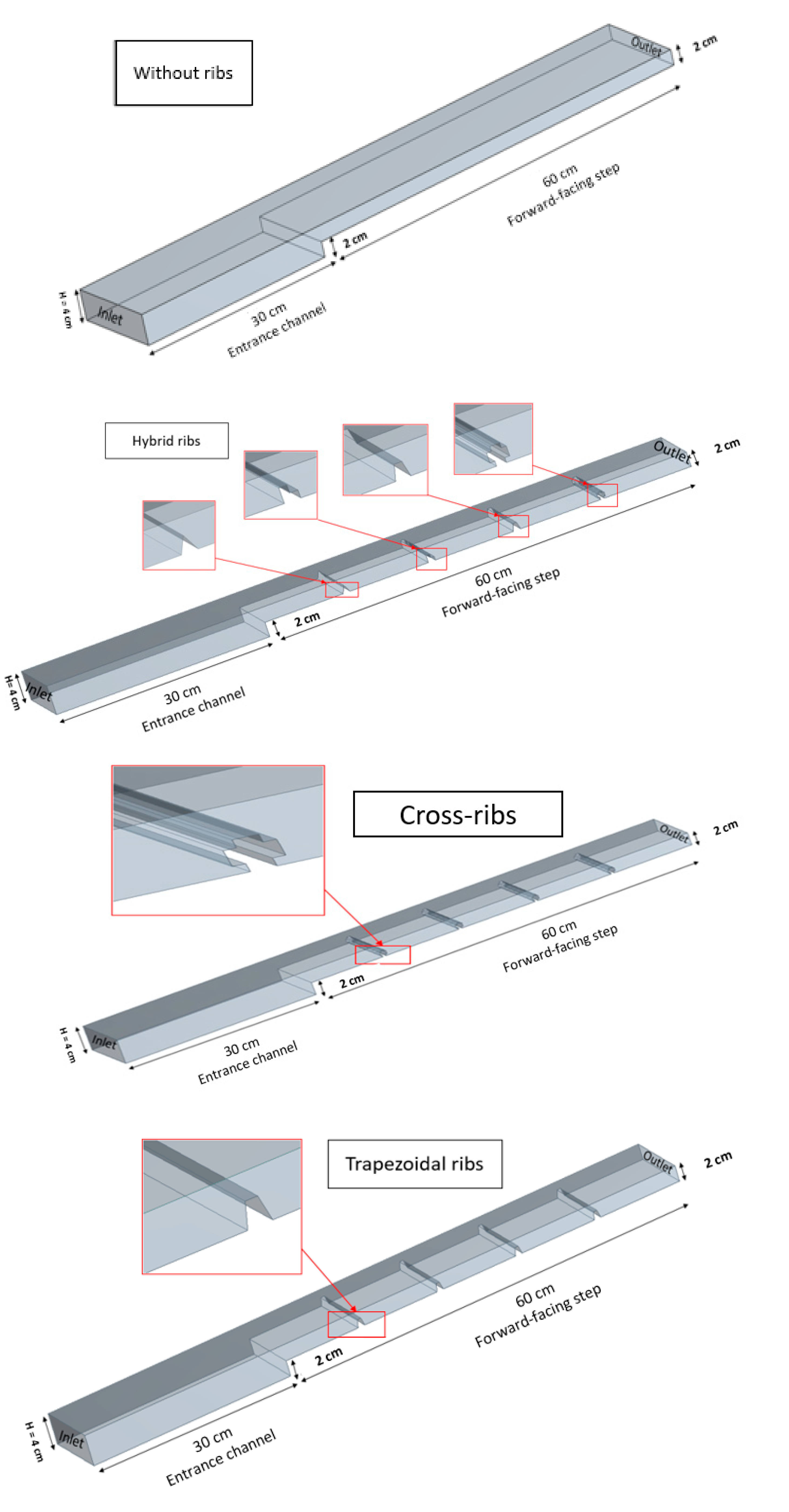
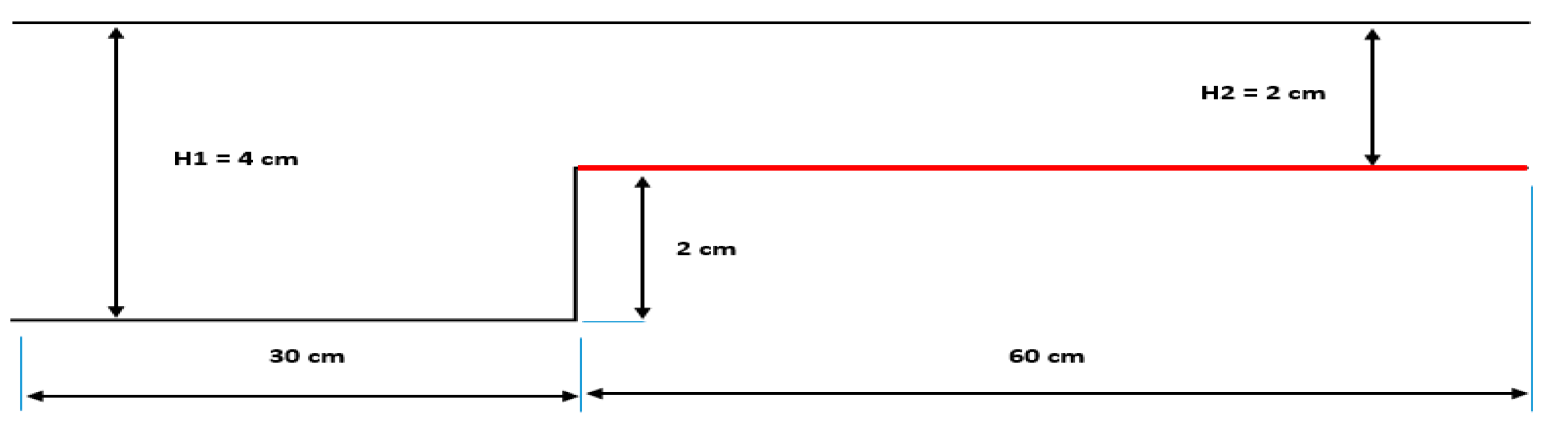
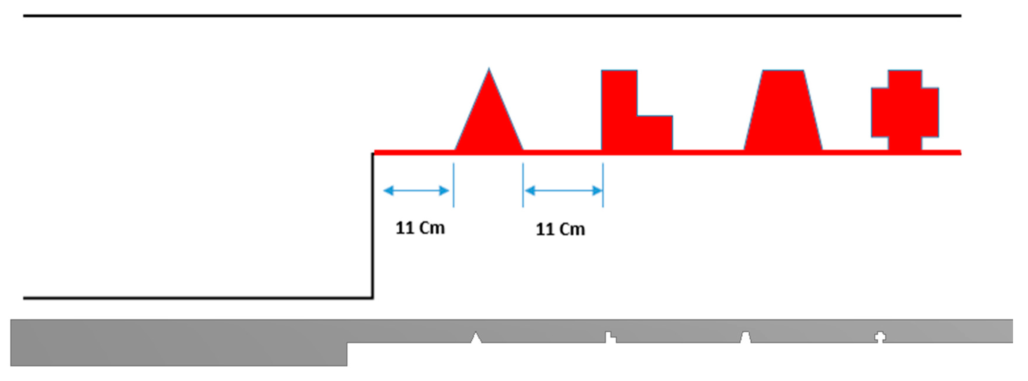
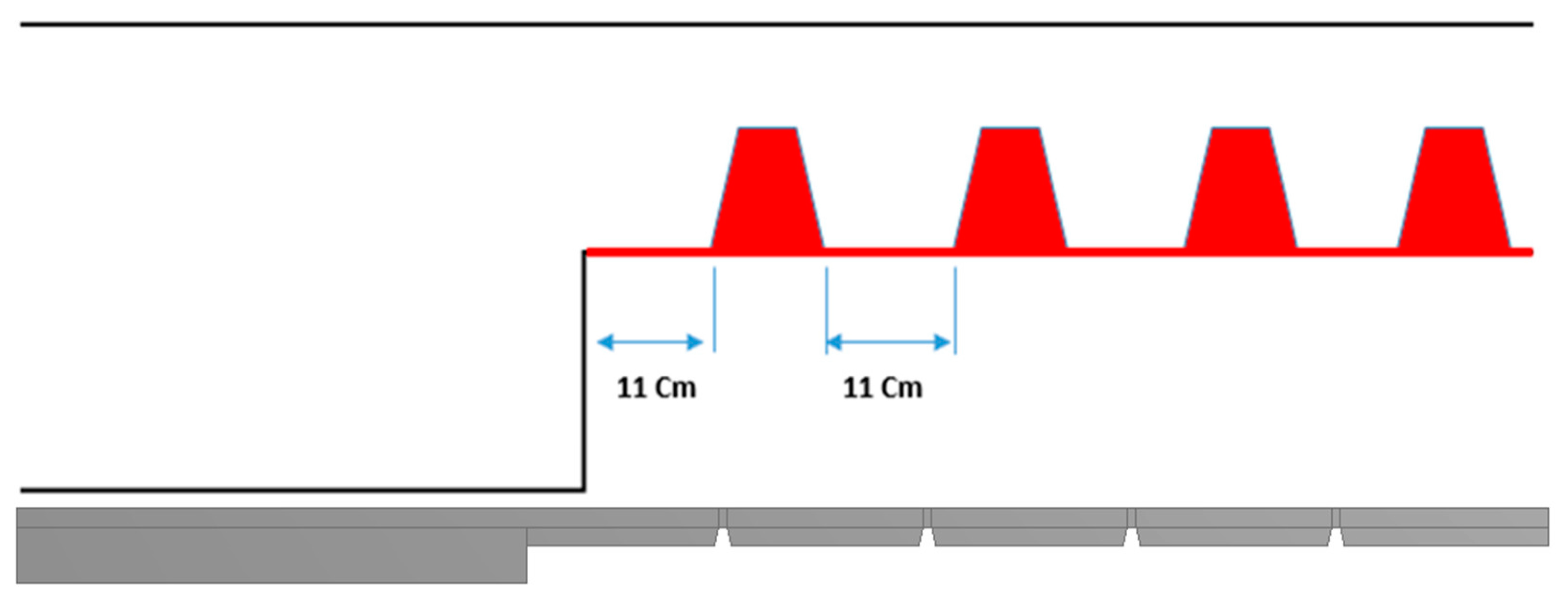
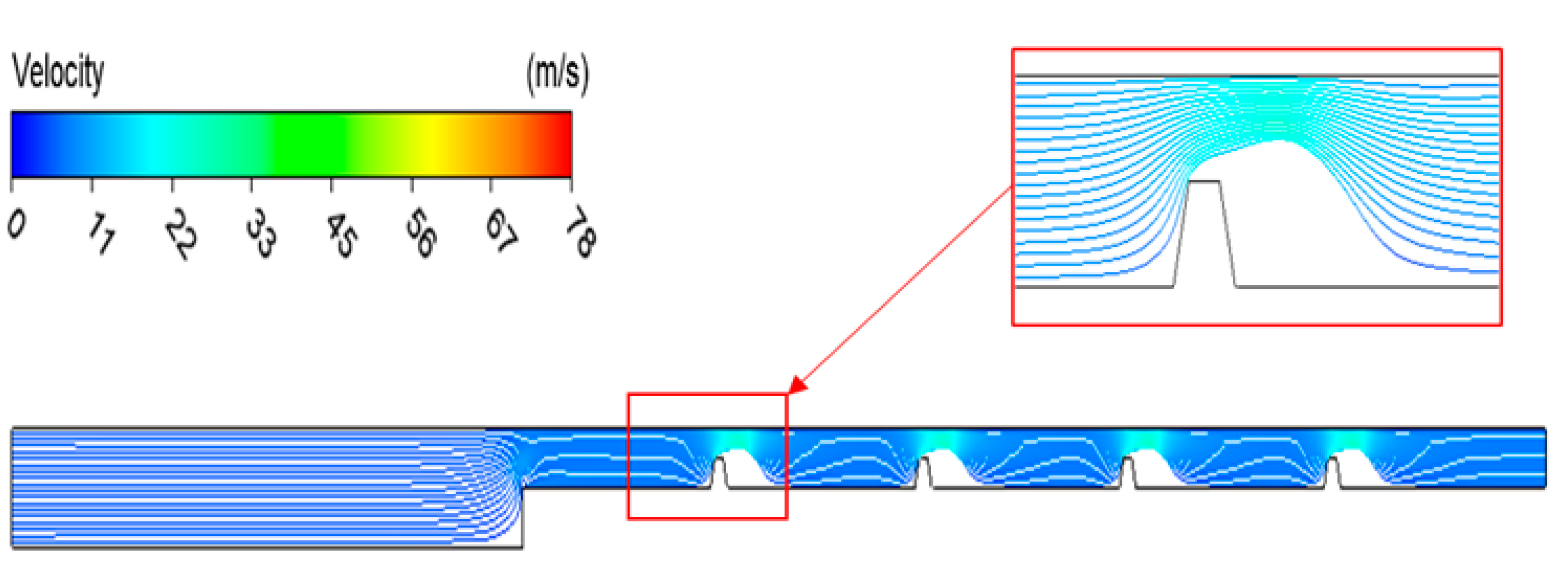
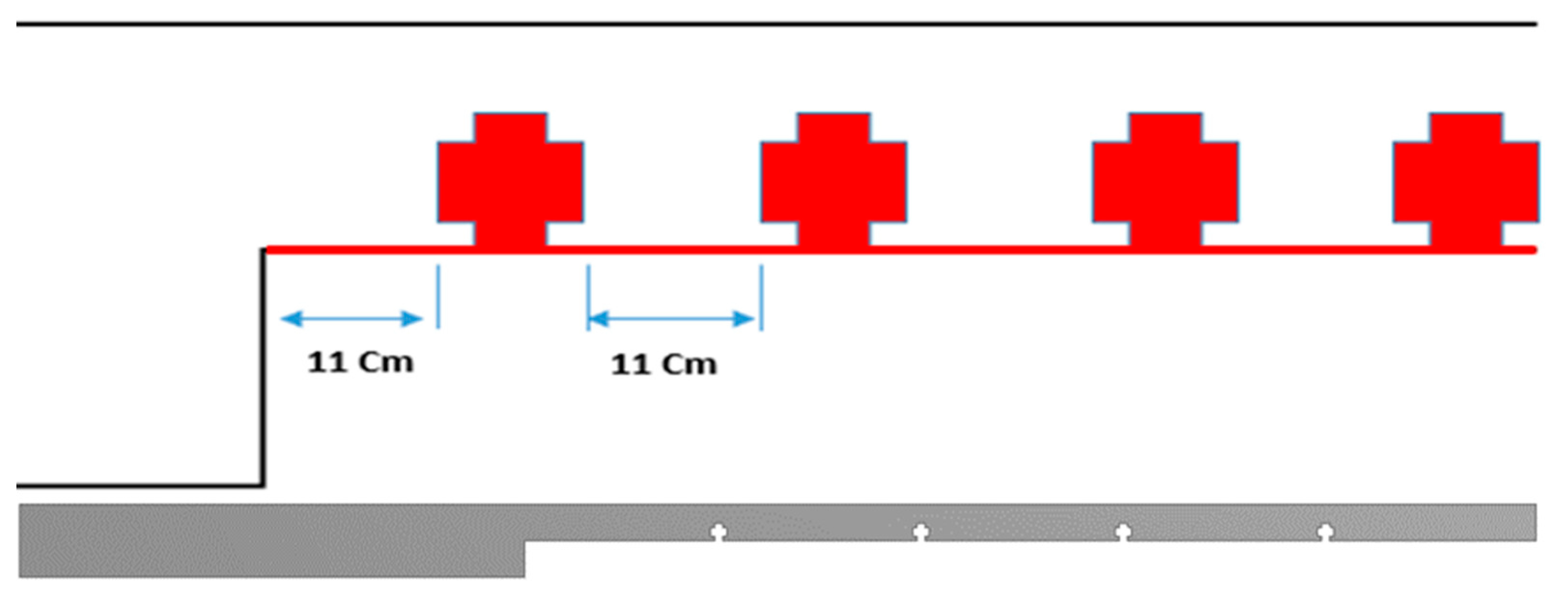
2. The Physical Model

This study’s suggested physical model is shown in Figure 1. Two-dimensional forced convection heat transfer under turbulent flow conditions, a forward-facing contracting channel (FFS) with and without ribs investigated. Four types of ribs (Triangular-rib, L-rib, Trapezoidal- rib, and Cross-rib) were used in this simulation with dimensions (1 cm × 1 cm) and 11 cm space between every two ribs. The total length (L) is 90 cm, with the entrance height (H1) 4 cm, the exit height (H2) 2 cm, the height of the step 2 cm, and the length of upstream 60 cm. Before and after each rib, the entire domain might achieve symmetrical flow and heat transfer. The top channel and the bottom wall upstream are insulated, while the bottom wall downstream is heated by constant heat flux (q = 2000 W/m2). Four ranges of Reynolds number changed, 10,000, 20,000, 30,000, and 40,000, are used for airflow. Figure 2 shows a forward-facing contracting channel (FFS) with and without ribs. The rib size and spacing were chosen based on previous research and empirical observations. The 1 × 1 cm rib size and 11 cm distance between them were selected. They are commonly used in similar studies and represent typical rib configurations in various engineering applications, such as heat exchangers, electronic cooling systems, and gas turbine blades.
In addition, previous studies have shown that these rib sizes and spacings significantly impact the flow field’s heat transfer and fluid dynamics. For instance, a study by Yang et al. [52] investigated the effects of rib size and spacing on heat transfer and pressure drop in a rectangular channel with rib turbulators. They found that smaller rib sizes and closer rib spacings resulted in higher heat transfer rates and pressure drops, while larger ribs and wider rib spacings had the opposite effect. Further, several other studies have investigated the impact of rib size and spacing on heat transfer and fluid dynamics in different geometries. For instance, a study by Xie et al. [53] investigated the effect of rib height and pitch on heat transfer and pressure drop in a wavy channel with rib turbulators. They found that increasing rib height and decreasing rib pitch can improve heat transfer performance while increasing pressure drop.
Moreover, the selection of rib geometries in our study is based on their practical applicability in the targeted engineering systems. Specifically, the rib size and spacing we have chosen are commonly used in the design of gas turbine blades and cooling channels in electronic devices. By investigating the effects of these specific geometries on the flow field’s heat transfer and fluid dynamics, our study aims to provide valuable insights into the design and optimization of these engineering systems.

3. The Problem Statement

3.1. Governing Equations

Based on FVM and constant fluid characteristics, governing equations for 2D turbulent heat transfer are solved. The relationships between continuity, momentum, and energy equations are shown below:
U i x i = 0
( U i   U j ) x j = p x i + x j ( μ U i x j   ρ u i u j ¯ )
( U i   T j ) x j = x i ( μ Pr T i x j   ρ u i t j ¯   )
The Reynolds stresses and heat fluxes are, respectively, set as:
  ρ u i u j ¯ = μ t ( U i x j + U j x i ) + 2 3 δ ij k ]
  ρ u i t j ¯ = μ t σ θ T i x j
The equations of the standard k-ɛ model can be written as:
ρ kU i   x j =   x j + [ ( μ + μ t σ k ) k x j ] +   ρ ( G b ε )
ρ ε U i   x j =   x j + [ ( μ + μ t σ k ) ε x j ] +   ρ ε k ( c 1 ε G b c 2 ε ε )
G b = μ t ( u i x j + u j x i ) u i x j
μ t = ρ c μ k 2 ε
The factors of the k-ɛ model are   C 1 ε = 1.44 , C 2 ε = 1.92 ,   C 3 ε = 0.09 ,   σ k = 1.0 , σ ε = 1.3 , and   Pr = 0.7 .
In order to achieve greater numerical accuracy, the second-order approach was used in this research. The convergence measure for momentum and energy was less than 10−8 for each repeat and less than 10−6 for the continuity equation.

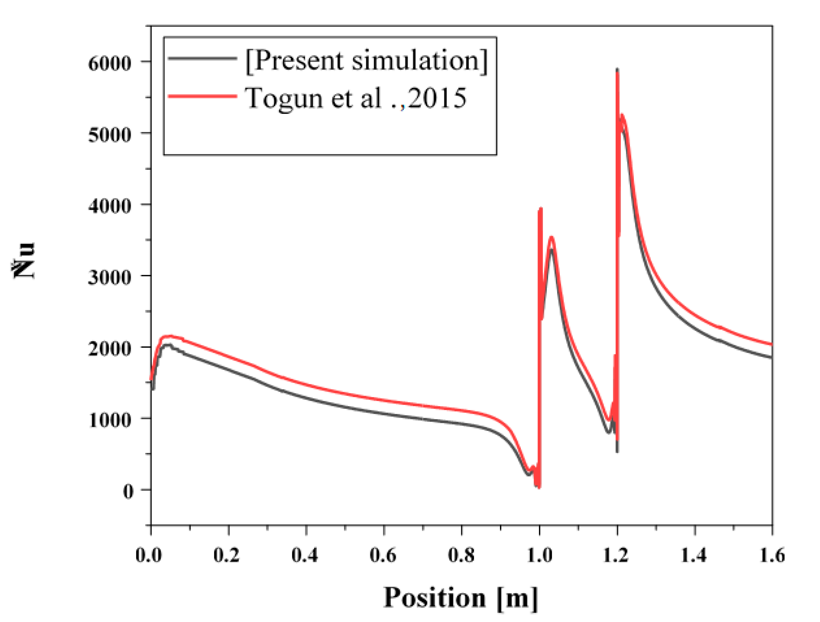
3.2. Grid Independent and Code Validation

Ansys. 19 software was used to study grid independence by increasing the grid elements and comparing the outlet temperature until it became stable; for nodes = 2108, 2801, 3956, 5331, 8341, 11,353, 14,361, the outlet temperature was 307, 313.5, 314.2, 314.7, 313.9, 313.7, 313.6 respectively, as shown in Figure 3. The difference between the temperature of the last two grids is less than 0,1K; therefore, a grid of 11,353 was adopted in this analysis. From what has been revealed by the previous literature for a turbulent flow and heat transfer of nanofluids in a double forward-facing step, and for the sake of checking our simulations, we have reconducted the work done by Togun et al. [30], over than Re > 104 and forced convection, as shown in Figure 4. The difference between the results of the local Nusselt number was less than 3%; hence, our present study was successfully tested.

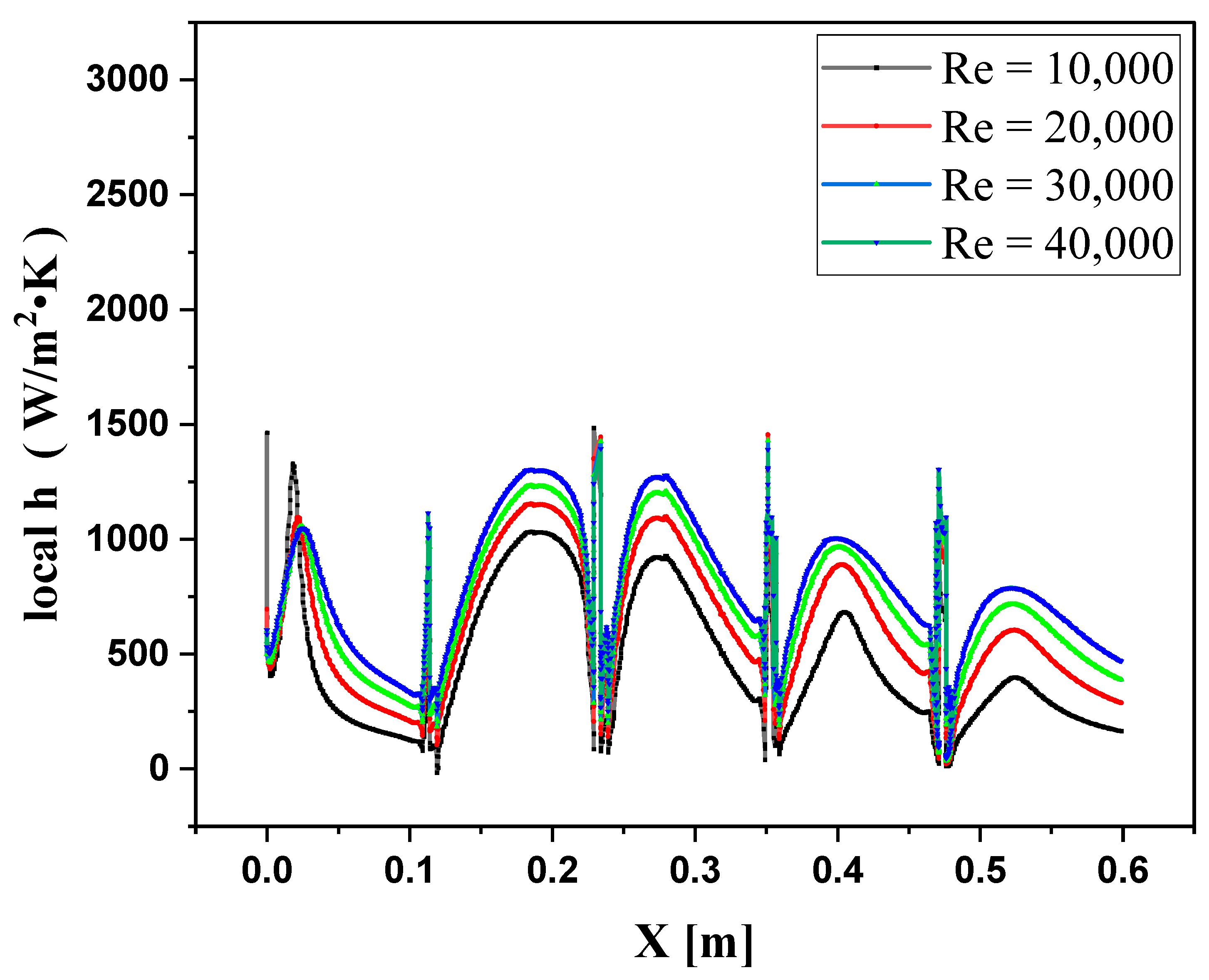
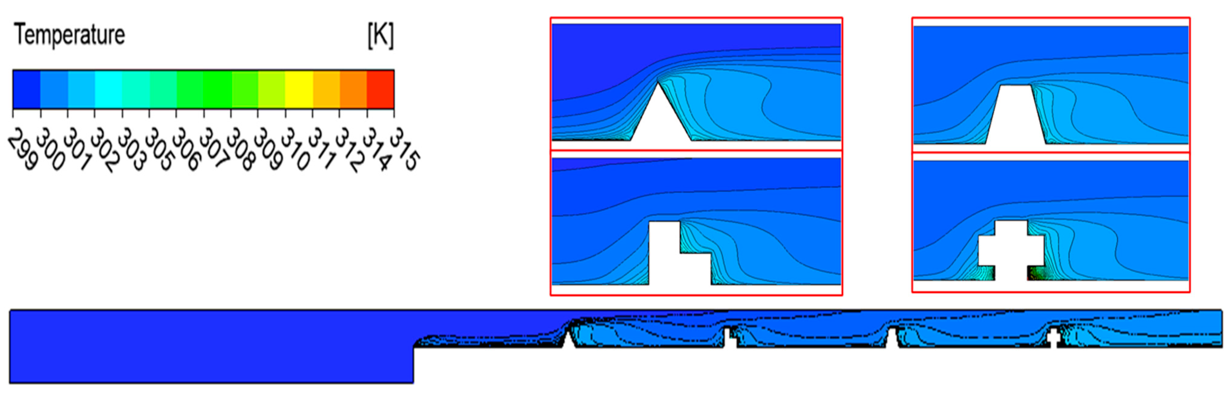
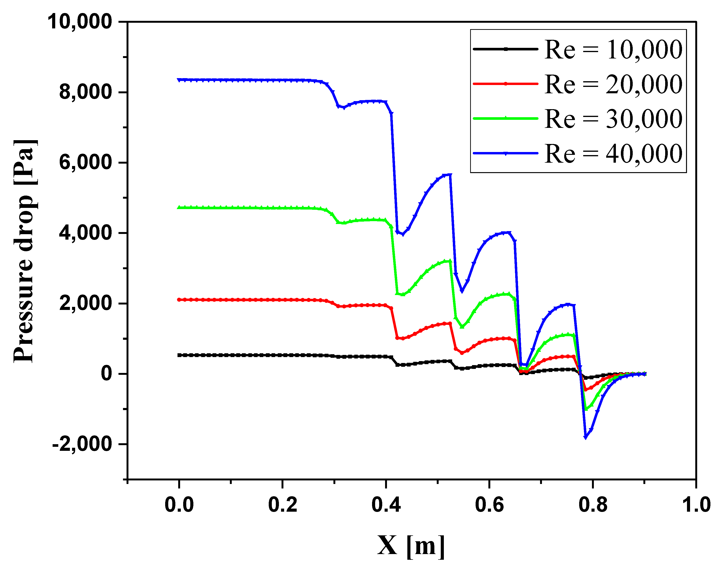
4. Results and Discussion

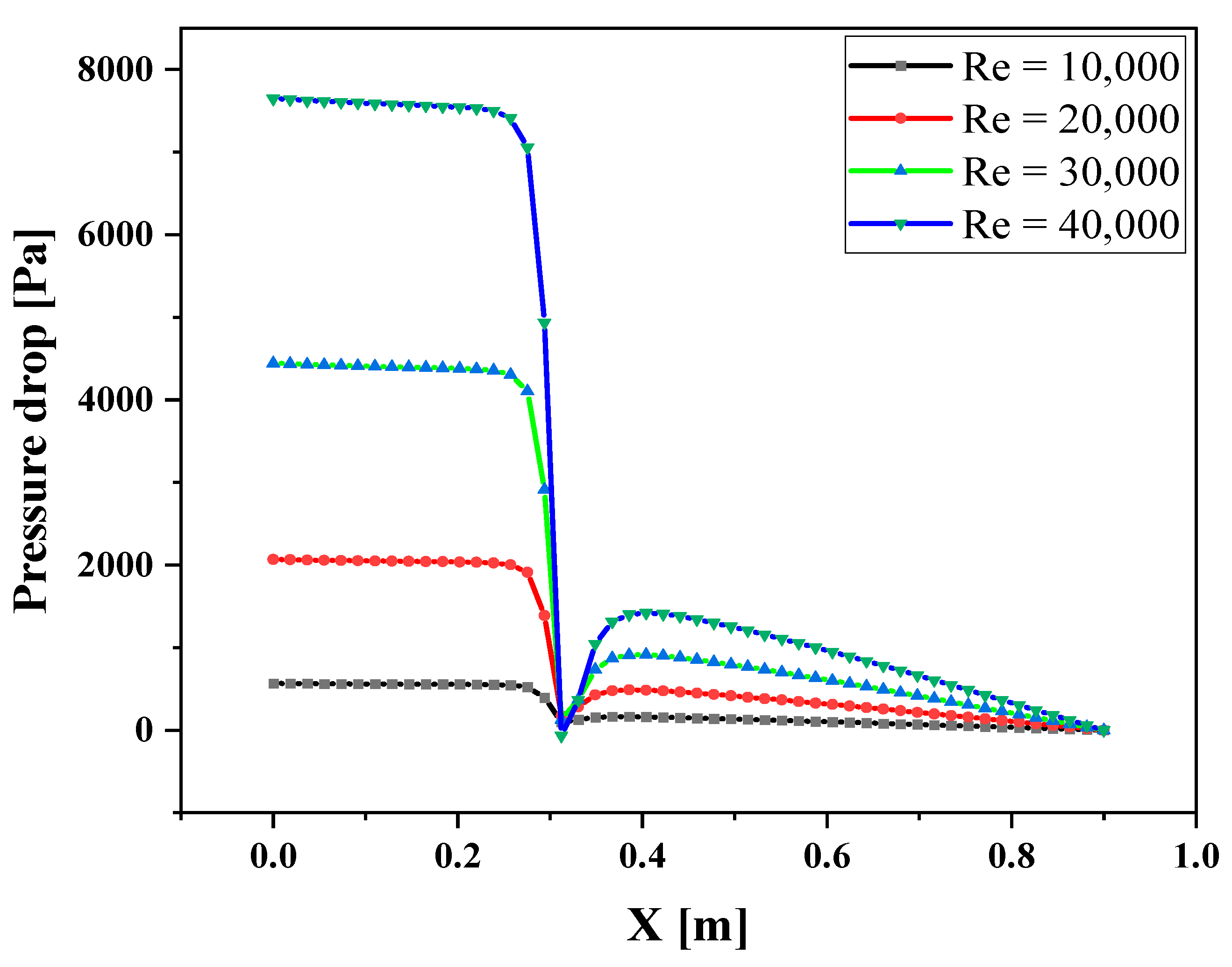
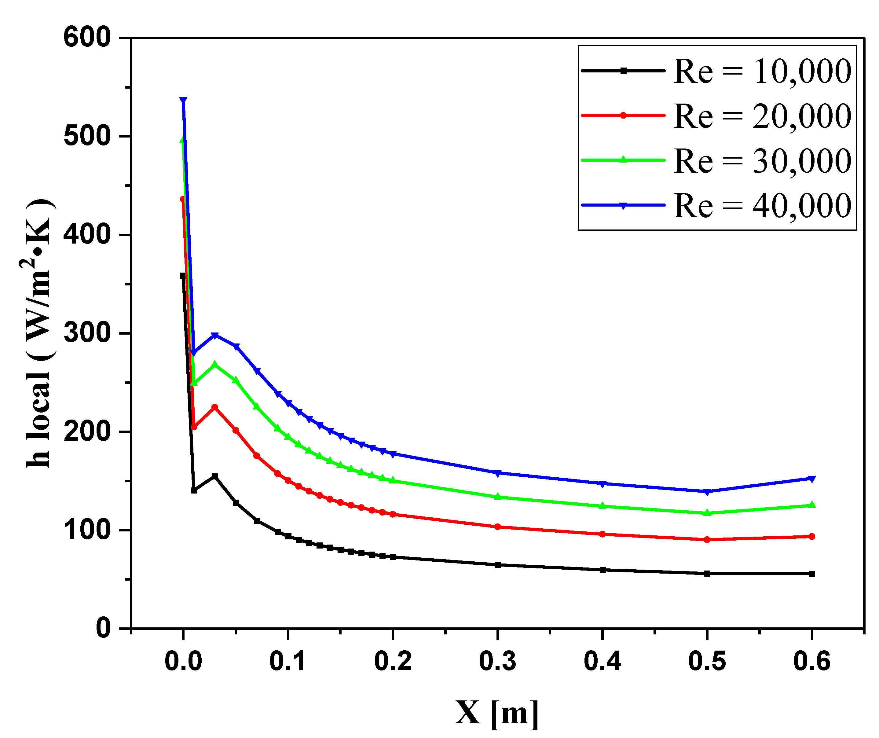
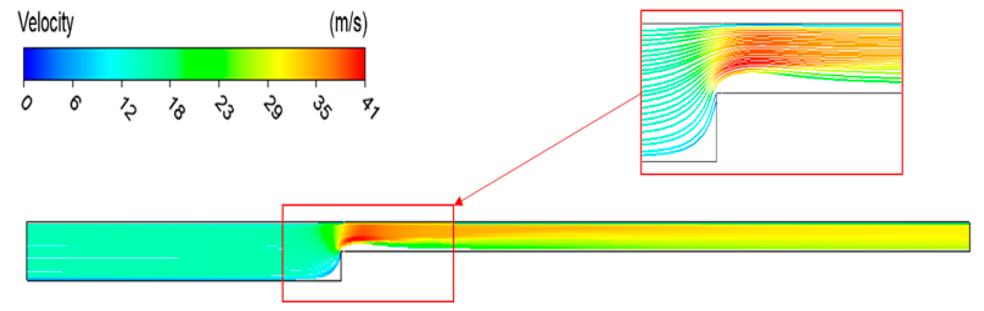
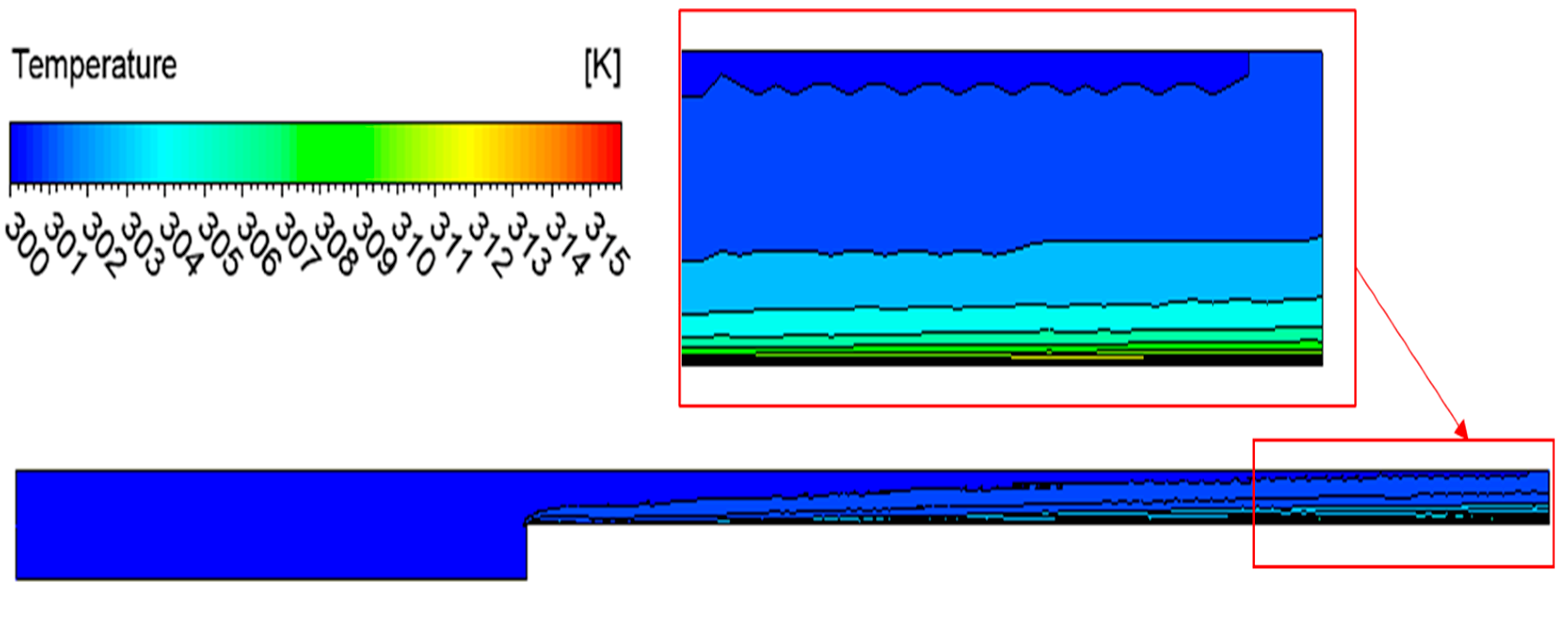
4.1. The Pressure Drop and Heat Transfer Coefficient without Ribs Shape

Pressure drop is an irreversible and unavoidable phenomenon that occurs for every flow rate in a tube unit, caused mainly by the conversion of the mechanical energy to heat by friction, variation in the altitude, and turbulence caused by a sudden flow change. The inaccurate pressure drop predictions cause different issues involving the indecent choice of the requested power supply.
In Figure 5, it can be observed that the fluid travels from the wider region to the narrower heated zone. Due to the constancy of the flow rate, the fluid velocity increases in the heated area. Figure 6 displays the pressure drop across the channel for different Reynolds numbers. The pressure drop begins with a relatively higher value in the wider section, directly proportional to the Reynolds number. At a Reynolds number of 40,000, the pressure drop is recorded as 780 Pa, while at a lower Reynolds number of 10,000, it is measured to be 60 Pa. The high Re (high velocity) between the fluid particles and the wall surface causes a more significant pressure drop. Therefore, the value of the pressure drop increase with increasing Re. The pressure drop values for various Re collapse at the point of changing the channel size, causing high friction, and for the higher Re, the pressure drop goes to the negative value due to the rebounding of the flow direction. In the narrower region of the channel, the less pressure drop starts with a lower value due to less friction, which is caused by a smaller surface area of the channel. Figure 7 shows the heat transfer coefficient in the heated channel for various values of the Re. The heat transfer coefficient starts with unstable values because of the irregular pattern of the flow. The heat transfer coefficient reduces as it flows in the heated channel because it increases the air temperature and reduces the difference between the air temperature and the walls. Increasing the Re increases the value of the heat transfer coefficient, whereas, at the outlet section, it registered 150 W/m2.k and 55 W/m2.k when the Re are 40,000 and 10,000, respectively.
Figure 8 illustrates the streamlined velocity contour for the higher flow rate (Re) case. The velocity starts with a specific value at the wide area; the velocity increases due to the constant flow rate when the flow channel becomes smaller. In the heated zone, the fluid lunches with the irrotational flow region generating a boundary layer below. The developing velocity profile generates and initiates the fully developed velocity profile. Due to generating the boundary layer between the flow and the wall at the entrance region (to the smaller channel), the velocity shows a higher value before it slows down at the fully developed region. The shear stress starts with a valve at the entrance region and exponentially reduces as the flow develops. Figure 9 shows the isothermal contours presented by the temperature distribution in the channels. The temperature increase due to the heating is insignificant as there is a long boundary layer at the region’s entrance in which the air is not in contact with the heated plate.

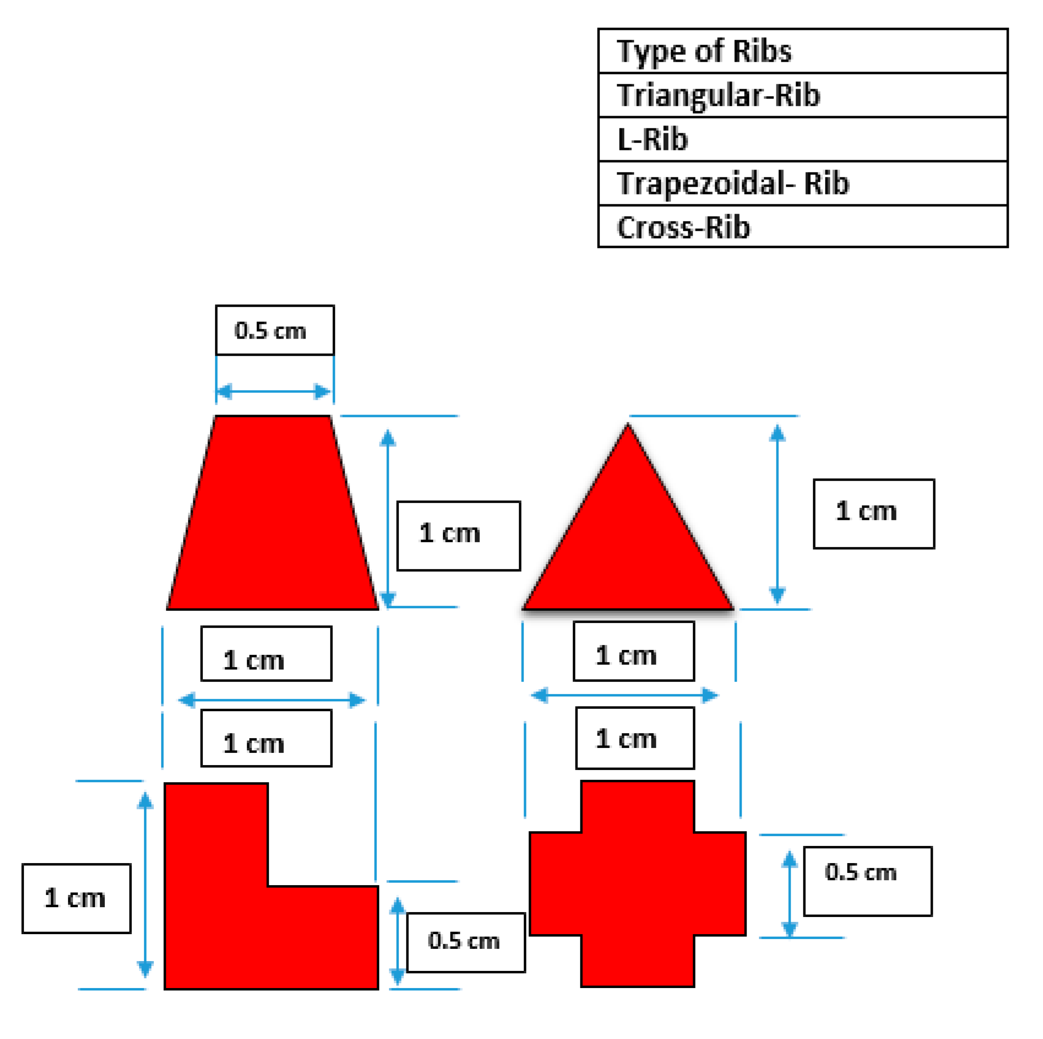
4.2. The Pressure Drop and Heat Transfer Coefficient of the Type of Ribs Shape

Different rib configurations are added to the heated plate’s internal surface to improve the unit’s thermal performance (Figure 10). The separation distance between these ribs is 11 cm. Figure 11 shows the variation in the pressure drop along the domain. At the entrance Zone (wide) area), the pressure drop shows a stable behavior for each value of Re. The change in the pressure drop Starts at the point of changing the diameter, causing a reduction in the pressure drop value due to the fluid rebound. After entering the heated section, the pressure drop sharply declines when it hits the rib on the left side. Its value increases gradually when the fluid flow (slips) over and behind the rib (right side) since the velocity increases in those areas.
The value of the pressure drops reduces after hitting each barrier (rib), and with the last rib (cross shape), this value drops to an opposing side due to rebounding most of the fluid in the opposite direction. The heat transfer coefficient for each value of Re along the heated wall is illustrated in Figure 12. The heat transfer coefficient shows a sharp increase in the region of each rib due to increasing the turbulence effect and the velocity caused by the small area between the top of the ribs and the upper wall. The heat transfer coefficient drops sharply behind each rib; then, it makes a small peak in the areas between the ribs due to generating a vortex.
Figure 13 shows the streamlined velocity for the case of using all types of ribs. The contours show a higher rate at the top of each rib due to the reduction of the flow’s cross-section area. Vortexes or swirls are appeared behind each rib, increasing the turbulence intensity of the fluid and helping to increase the heat transfer rate to the liquid. Because of the point shape of the top of the triangle rib, the stream shows a faster movement and generates a large vertex behind that rib compared to the others. The isothermal conduct is presented by the temperature distribution for the case of using various rib types and illustrated in Figure 14. The higher temperature appears in the region attached to the heated wall, especially in the sword places, since the fluid circulates in those areas and gains more heat from the surface area. The temperature recorded a higher value around the cross rib since this rib has many straight angles, and several vortexes (even no small size shown in the streamlined contours) generate and cause the higher temperature in those areas.

4.3. The Pressure Drop and Heat Transfer Coefficient of Triangular-Ribs Shape

Utilizing each type of rib (separately) in this work should be investigated to explore the effect of the rib’s configurations on the thermal performance. In this part, the impact of the tringle ribs on the system has been investigated, as shown in Figure 15. Figure 16 shows the Pressure drop behavior in the tested channel for different values of Re at the steady state case. The pressure drop reduces sharply when the flow hits each rib; then, it increases slightly behind the rib as the flow slips over the rib on the right side. The average pressure drop value reduces by passing each rib and shows a negative value at the last one, confirming a flow back of the fluid. The pressure drops registered 8300 Pa and 0 Pa at the entrance region and the area behind the ribs, respectively, when Re is 40,000.
The heat transfer coefficient along the heated plate is shown in Figure 17. The value starts in the unsteady range and drops to a stable one. Before that, the flow hits the tringle rib, causing an increase in the heat transfer coefficient due to the higher surface area and generating vortexes beside the ribs. The convective heat transfer reaches the maximum value at the top region of the rib; then, it drops down, reaching the minimum value when the flow is on the heated wall. The minimum value of the heat transfer coefficient is caused by generating the boundary layer over the heating surface. The convective heat transfer is directly proportional to the Re since the high Re (high flow rate) helps the fluid absorb more heat from the surface of the plate. The average heat transfer coefficient of the liquid in the case of Re (40,000) is 290 W/m2.k, whereas when Re (10,000), the heat transfer coefficient is 80 W/m2.k.
The streamlined contour shows the flow rate along the channel (Figure 18). Worth to note that the velocity of the fluid increases behind each rib since the cross-section area of the channel becomes smaller. Due to the sharp peak of the tringle ribs, the fluid flows far away from the heated surface, causing a gap over the plate. Swirls appear behind each rib, occupying the gap between the liquid and the heated surface. The isothermal contours in Figure 19 show the temperature distribution along the channel. The area of a fast flow rate shows lower temperature since the fluid is away from the heated surface and has a short time to absorb heat from the heater. The maximum temperature appears behind the ribs, especially in the swirl area, because the fluid circulation in the vortex helps to gain more heat from the surface.

4.4. The Pressure Drop and Heat Transfer Coefficient of L-Ribs Shape

Applying the L shape of ribs to the system was also explored for various Re in the test section (Figure 20). The pressure drop, in this case, shows a stable manner in the wide entrance area and reduces when the flow hits the wall of reduction since some fluid flows back (Figure 21). In the heated region, the pressure drop reduces when it meets the rib and then rises gradually due to slipping over the rib and sharply drops by the other rib. The average pressure drop reduces after each rib. At the last one, it falls to the negative value reflecting an increase in the pressure—the pressure drop increases with increasing the Re since the faster flow causes higher friction. Generally, in this case, when Re equals 40,000, the pressure drop is higher than in the cases where Re equals 10,000, 20,000, and 30,000 by 12, 3.8, and 1.8 times, respectively.
In the heated surface area, the heat transfer coefficient starts with the developing region and reduces gradually at the territory of each rib; the heat transfer coefficient sharply increases due to increasing the surface area on the one hand and the fast flow on the other (Figure 22). The heat transfer coefficient appears to plateau in the spaces between the ribs due to generating a swirl on the heated surface. The average heat transfer coefficient in the cases of Re equals 40,000, and 10,000 are 600 W/m2.k and 300 W/m2.k, respectively. Figure 23 shows the flow velocity and the stream along the channel. The rate shows a noticeable increase when the channel diameter reduces, and the flow accelerates more when it passes each rib, generating more turbulency between the ribs, represented as vortexes. The sharp cut part of the L shape also produces more turbulency on the flows, even if no swirl appears on the streamlined figure. This influence is shown in Figure 24, which illustrates a higher temperature in those places. The figure shows a higher temperature in the areas attached to heated surfaces and around the ribs since the fluid circulates and gains more heat. However, the temperature shows a colder state in the regions far from the heated surface, and the flow passes quickly since the fluid has not had sufficient time to gain heat from the heater.

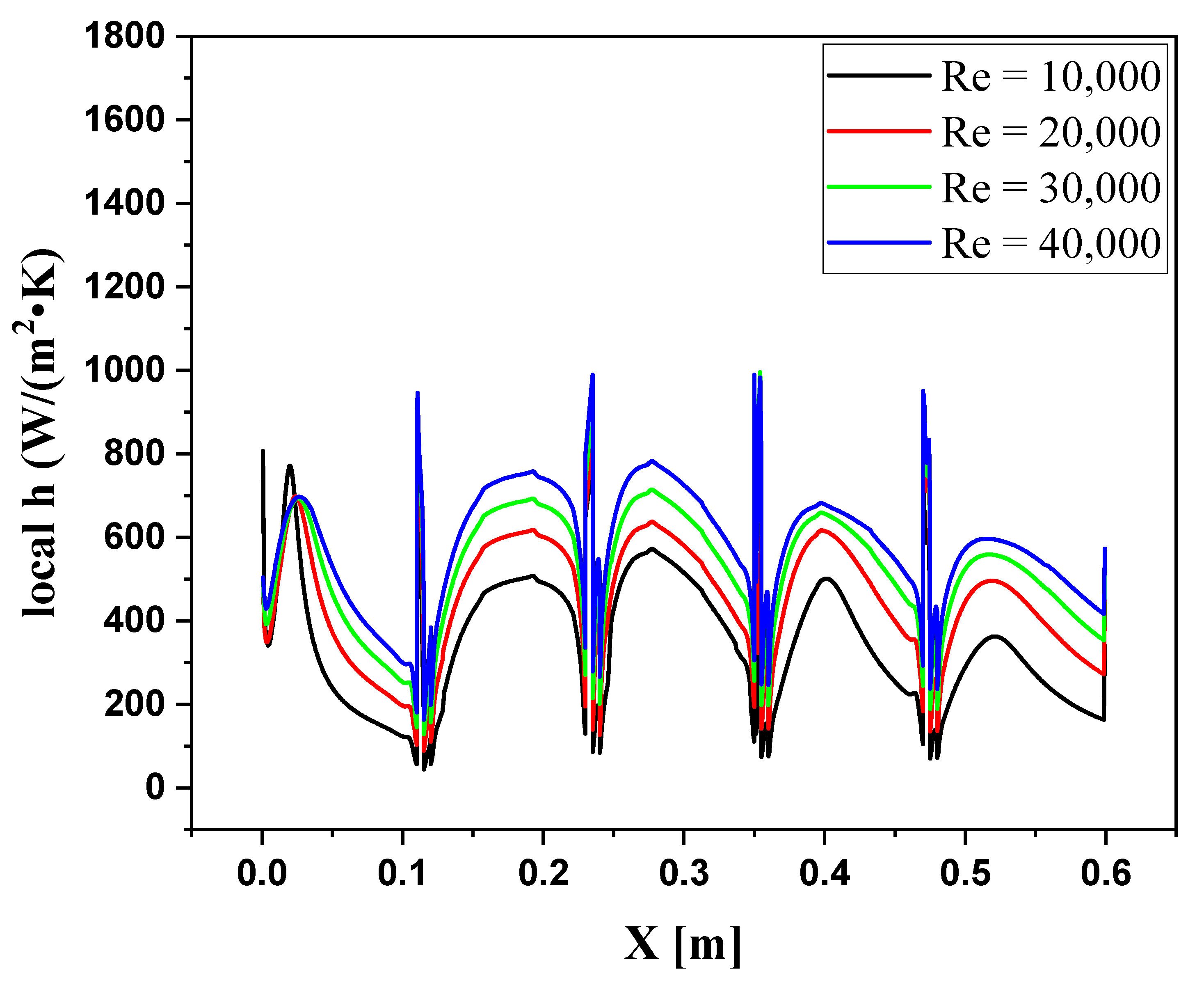
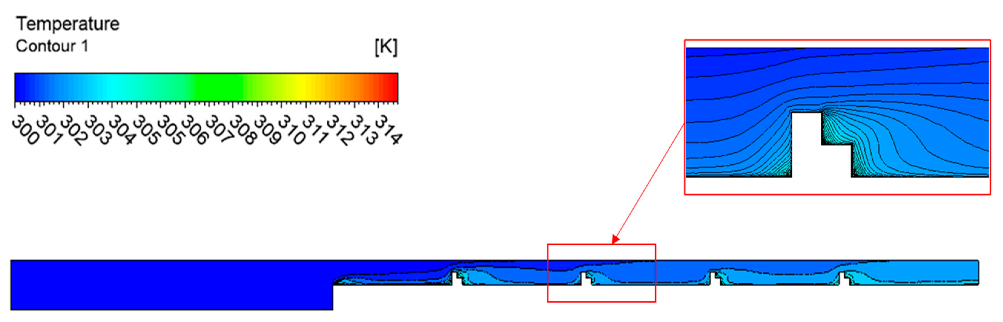
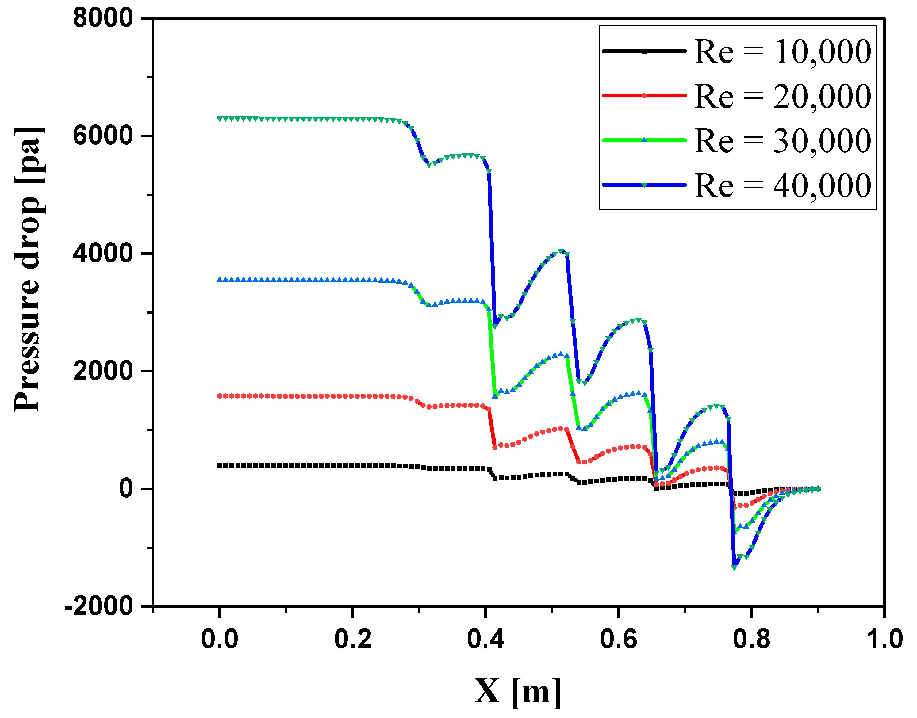
4.5. The Pressure Drop and Heat Transfer Coefficient of Trapezoidal-Ribs Shape

The thermal performance was analyzed in this study for the trapezoidal rib use in the channel (Figure 25). Similar to the previous cases, the pressure drop sets out in uniform levels for different Re at the entrance region, as shown in Figure 26. Worth to note that, not expectedly, the pressure drop starts at various values in each case, even though the initial conditions are the same for the different instances of the ribs. This behavior is due to the general ribs’ impact on the flow, which develops till the steady state. The pressure drop reduces sharply at meeting each rib and slightly increases when the flow slips on the rib due to increasing friction. At the last rib, the pressure drop reduces to a negative value indicating that the flow moves back. The pressure drop begins with 6300, 3700, 1700, and 250 Pa, when the Re is 40,000, 30,000, 20,000, and 10,000, respectively. Continuously slipping the flow over the heater reduces the convective heat transfer. A sudden increase occurs when the fluid hits the ribs due to the fast flow of the liquid in those areas and the large heat transfer surface areas around the ribs (Figure 27). The average heat transfer coefficient in the heated channel is 700 W/m2.k when Re is 40,000, and this value reduces to 400 W/m2.k at Re, equal to 10,000.
From the streamline velocity figure (Figure 28), the flow becomes faster when the fluid enters the heated zone; then, by reducing the channel at the rib’s areas, the fluid moves faster (shown in red). The top edge of the rib scatters the fluid upward, and then some of the fluid moves downward due to gravity. Swirls appear behind each rib as the pressure drops sharply at those regions. Due to the constant flow rate, the outlet section velocity is equal to that at the entrance of the heated section. The isothermal contours illustrated in Figure 29 clearly show that the higher temperatures are at the sides of the ribs, especially the right side, since the flow circulates there in a swirl allowing the fluid to gain more heat from the surface. The colder region also appears on the fast flow that is scatted from the ribs since it is far away from the heated surface, too fast, and has not had enough time to absorb heat from the surface.

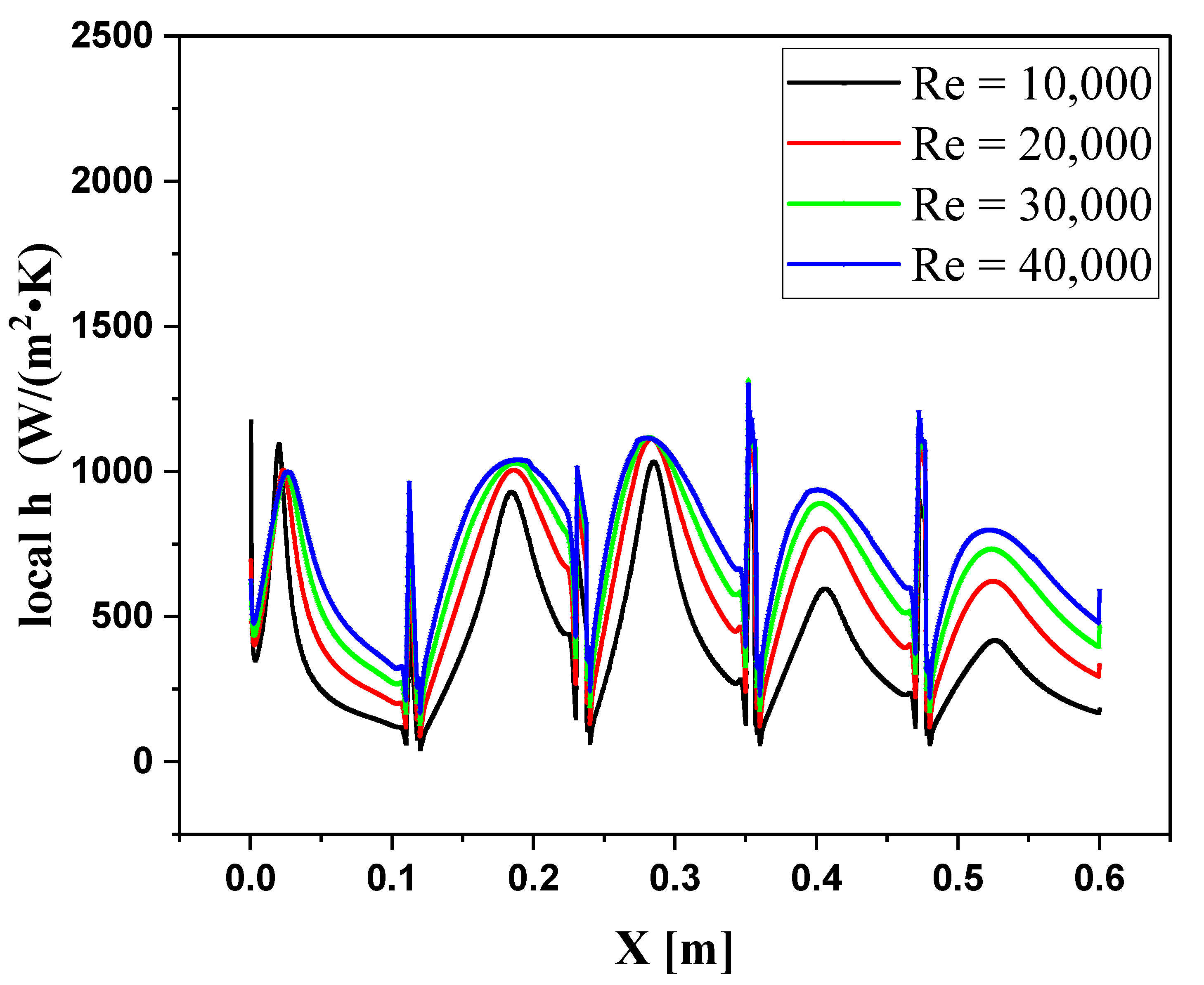
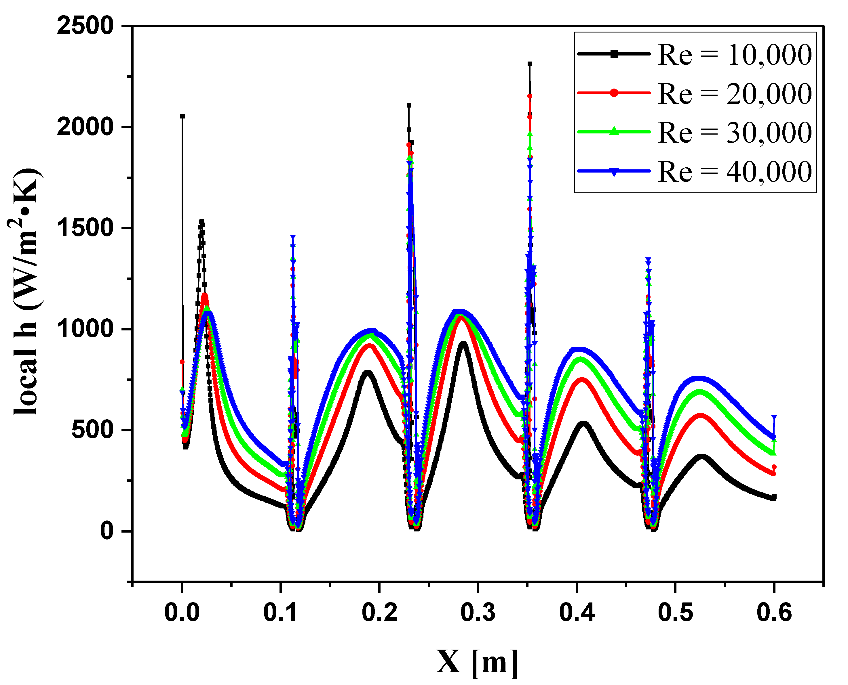
4.6. The Pressure Drop and Heat Transfer Coefficient of Cross-Ribs Shape

The cross ribs have been used in the system to finalize the heat transfer evaluation of this work, as shown in Figure 30. Figure 31 shows the pressure drop in the channel for various values of Re. The pressure drops to start with a constant value at a steady state condition for each Re; this value decreases when the fluid hits the reduction wall. The pressure drop increases slightly when the fluid flows between the ribs and collapses at the meeting region with the ribs. The average pressure drop reduces at each rib and goes to a negative value with the last rib. The pressure drop increases with the Re, starting with 5800 Pa and 450 Pa when Re are 40,000 and 10,000, respectively. In this case, the heat transfer coefficient is directly proportional to the Re (Figure 32). The average thermal coefficients are 750, 650, 600, and 450 W/m2.k when the Re equals 40,000, 30,000, 20,000, and 10,000, respectively. The convective heat transfer drops sharply when the fluid flows on the heated plate and rises when the fluid runs around the ribs since the velocity increases due to the small stream area above the ribs.
Over each rib, the heat transfer coefficient makes a high narrow peak. Figure 33 shows a velocity stream contour of the fluid in the channel. Two main points can be observed here; firstly, the velocity becomes faster when it enters the heated zone and accelerate more when it passes over the ribs. Secondly, due to drifting the flow upward when the fluid hits the top corner of the rib, a cavity appears behind the ribs, and vortexes generate in those areas. The isothermal contour in the heating channel is shown in Figure 34. The colder region appears at the top channel’s location since the velocity of the fluid is too fast and the flow is far from the heating surface. The warmer regions appear behind the ribs (at the areas generating the swirls), and in front, the ribs on the lower side as the fluid stuck in that region. The swirls and stuck fluid help the flow to gain more heat from the heating surface.
Figure 35 shows the pressure drops for all the studied cases at various Re. The case without ribs shows a slight increase with increasing the Re, and this change considerably increases with utilizing ribs. The shapes of the ribs influence the average pressure drops in the channel since it directly affects the flow and changes the flow patterns. The tringle ribs have a more significant impact than the other ribs configurations on the pressure drop; however, the cross ribs show a lower effect. At Re equals 40,000, the average pressure drop is 5000 Pa, which is higher than that in the cases using the cross ribs and the case without ribs by 1700 Pa and 4750 Pa, respectively. Figure 36 shows the heat transfer coefficient for all the studied cases at various Re. For the case without ribs, the heat transfer coefficient starts at 100 W/m2.k when Re is 10,000 and increases to 200 W/m2.k when the Re increases to 40,000. The best improvement in the heat transfer coefficient appears by applying the hybrid ribs, where its value equals 460 W/m2.k when Re is 10,000 and increases by 70% when the Re rises to 40,000. When Re equals 40,000, the hybrid case’s heat transfer coefficient is higher than those of trapezoidal, cross, and L shape ribs by 8%, 18%, and 39%, respectively.

5. Conclusions

In conclusion, this numerical investigation evaluated the impact of utilizing hybrid ribs in a heated channel with varying Reynolds numbers on heat transfer. The results were compared against simulations that utilized each rib type separately with the same boundary conditions. The forward-facing contracting channel (FFC) with and without ribs was analyzed under turbulent flow conditions using two-dimensional forced convection heat transfer. The simulations incorporated four rib configurations (triangular, L-shaped, trapezoidal, and cross) separated by 1 cm and 11 cm distances. Results showed that the values of the Reynolds number were proportional to the heat transfer coefficient and pressure drop, with the ribs improving the heat transfer coefficient and increasing the pressure drop. Despite having the same boundary conditions, the pressure drop at the channel’s entrance was different for each rib configuration due to the ribs affecting the general flow of the system. The triangle ribs had a more significant impact on the pressure drop, while the cross ribs had a lower effect. The use of hybrid ribs demonstrated improved thermal performance compared to using each rib type separately because of generating various flow patterns. This study demonstrates encouraging developments in thermal performance through these techniques. Future work can examine the impact of different fluids, including nanofluids, and varying heat, geometry, and flow modes.

Author Contributions

Conceptualization, H.T. and S.H.; methodology, A.M.A.; software, S.H.; validation and formal analysis, M.A.-T.; investigation, R.Z.H. and T.A.; resources, H.A.H.; writing—review and editing, H.I.M.; visualization, A.W.A.-F.; supervision, H.T. All authors have read and agreed to the published version of the manuscript.

Funding

This research received no external funding.

Conflicts of Interest

The authors declare no conflict of interest.

References

  1. SriHarsha, V.; Prabhu, S.; Vedula, R. Influence of rib height on the local heat transfer distribution and pressure drop in a square channel with 90° continuous and 60° V-broken ribs. Appl. Therm. Eng. 2009, 29, 2444–2459. [Google Scholar] [CrossRef]
  2. Togun, H.; Homod, R.; Abdulrazzaq, T. Hybrid Al2O3-Cu/water nanofluid flow and heat transfer over vertical double forward-facing step. Therm. Sci. 2021, 25, 3517–3529. [Google Scholar] [CrossRef]
  3. Promyoog, P. Heat transfer and pressure drop in a channel with multiple 60° V-baffles. Int. Commun. Heat Mass Transf. 2010, 37, 835–840. [Google Scholar]
  4. Togun, H.; Hakim; Sultan, S.; Anjum, I.; Kazi, S. An experimental study of turbulent heat transfer separation external in an annular passage. In Proceedings of the International Conference on Applications and Design in Mechanical Engineering (ICADME 2009), Shenzhen, China, 19–20 September 2015. [Google Scholar]
  5. Sherry, M.; Jacono, D.L.; Sheridan, J. An experimental investigation of the recirculation zone formed downstream of a forward facing step. J. Wind. Engng. Ind. Aerodyn 2010, 98, 888–894. [Google Scholar] [CrossRef] [Green Version]
  6. Kazi, H.T.S.; Badarudin, A. A Review of Experimental Study of Turbulent Heat Transfer in Separated Flow. Aust. J. Basic Appl. Sci. 2011, 5, 489–505. [Google Scholar]
  7. Togun, H.; Salman, Y.; Aljibori, H.S.S.; Kazi, S. An experimental study of heat transfer to turbulent separation fluid flow in an annular passage. Int. J. Heat Mass Transf. 2011, 54, 766–773. [Google Scholar] [CrossRef]
  8. Gupta, A.; SriHarsha, V.; Prabhu, S.; Vedula, R. Local heat transfer distribution in a square channel with 90° continuous, 90° saw tooth profiled and 60° broken ribs. Exp. Therm. Fluid Sci. 2008, 32, 997–1010. [Google Scholar] [CrossRef]
  9. Oon, C.; Togun, H.; Kazi, S.; Badarudin, A.; Sadeghinezhad, E. Computational simulation of heat transfer to separation fluid flow in an annular passage. Int. Commun. Heat Mass Transf. 2013, 46, 92–96. [Google Scholar] [CrossRef]
  10. Lanzerstorfer, D.; Kuhlmann, H. Three-dimensional instability of the flow over a forward-facing step. J. Fluid Mech. 2012, 695, 390–404. [Google Scholar] [CrossRef]
  11. Hussein, T.; Kazi, S.; Kadhum, A.A.H.; Badarudin, A.; Sadeghinezhad, M.A.E. Numerical Study of Turbulent Heat Transfer in Separated Flow: Review. Int. Rev. Mech. Eng. 2013, 7, 337–349. [Google Scholar]
  12. Togun, H.; Homod, R.Z.; Yaseen, Z.M.; Abed, A.M.; Dhabab, J.M.; Ibrahem, R.K.; Dhahbi, S.; Rashidi, M.M.; Ahmadi, G.; Yaïci, W.; et al. Efficient Heat Transfer Augmentation in Channels with Semicircle Ribs and Hybrid Al2O3-Cu/Water Nanofluids. Nanomaterials 2022, 12, 2720. [Google Scholar] [CrossRef] [PubMed]
  13. Hattori, H.; Nagano, Y. Investigation of turbulent boundary layer over forward-facing step via direct numerical simulation. Int. J. Heat Fluid Flow 2010, 31, 284–294. [Google Scholar] [CrossRef]
  14. Togun, H.; Abdulrazzaq, T.; Kazi, S.; Badarudin, A.; Ariffin, M. Heat Transfer to Laminar Flow over a Double Backward v-Facing Step. Int. J. Mech. Ind. Sci. Eng. 2013, 7, 673–678. [Google Scholar]
  15. Scheit, C.; Esmaeili, A.; Becker, S. Direct numerical simulation of flow over a forward-facing step—Flow structure and aeroacoustic source regions. Int. J. Heat Fluid Flow 2013, 43, 184–193. [Google Scholar] [CrossRef]
  16. Biswas, G.; Breuer, M.; Durst, F. Backward-Facing Step Flows for Various Expansion Ratios at Low and Moderate Reynolds Numbers. J. Fluids Eng. 2004, 126, 362–374. [Google Scholar] [CrossRef]
  17. Armaly, B.F.; Durst, F.; Pereira, J.C.F.; Schönung, B. Experimental and theoretical investigation of backward-facing step flow. J. Fluid Mech. 1983, 127, 473–496. [Google Scholar] [CrossRef]
  18. Oztop, H.F.; Mushatet, K.S.; Y11maz, I. Analysis of turbulent flow and heat transfer over a double forward facing step with obstacles. Int. Commun. Heat Mass Transf. 2012, 39, 1395–1403. [Google Scholar] [CrossRef]
  19. Sano Masatoshi, S.I.; Kenichiro, S. Control of turbulent channel flow over a backward-facing step by suction. J. Fluid Sci. Technol. 2009, 4, 188–199. [Google Scholar] [CrossRef] [Green Version]
  20. Abe, K.; Kondoh, T.; Nagano, Y. A new turbulence model for predicting fluid flow and heat transfer in separating and reattaching flows—I. Flow field calculations. Int. J. Heat Mass Transfer. 1994, 37, 139–151. [Google Scholar] [CrossRef]
  21. Abe, K.; Kondoh, T.; Nagano, Y. A new turbulence model for predicting fluid flow and heat transfer in separating and reattaching flows—II. Thermal field calculations. Int. J. Heat Mass Transfer. 1995, 38, 1467–1481. [Google Scholar] [CrossRef]
  22. Vogel, J.C. Heat Transfer and Fluid Mechanics Measurements in the Turbulent Reattaching Flow Behind a Backward-Facing Step; Stanford University: Stanford, CA, USA, 1984. [Google Scholar]
  23. Terekhov, V.I.; Smul, Y.I.; Sharov, K.A. Experimental investigation of the separation flow structure behind a step in the presence of passive perturbation. Prikl. Mekh. Tekh. Fiz. 2016, 57, 207–215. [Google Scholar]
  24. Zhdanov, V.L.; Ivanov, D.A.; Smul’Skii, Y.I.; Terekhov, V.I. Influence of the Preseparation Flow Structure on the Characteristics of the Separation Region Behind a Backward-Facing Step. J. Eng. Phys. Thermophys. 2018, 91, 628–640. [Google Scholar] [CrossRef]
  25. Terekhov, V.I.; Dyachenko, A.Y.; Smulsky, Y.I. Heat and mass transfer behind a backward-facing step in the presence of detached vortex generators. AIP Conf. Proc. 2020, 2211, 080001. [Google Scholar] [CrossRef]
  26. Elwekeel, F.N.M.; Zheng, Q.; Abdala, A.M.M. Numerical Study of Turbulent Flow Through Rib-Roughened Channels with Mist Injection. Heat Transfer. 2014, 5A, 1–10. [Google Scholar]
  27. Tanda, G. Heat transfer in rectangular channels with transverse and V-shaped broken ribs. Int. J. Heat Mass Transf. 2004, 47, 229–243. [Google Scholar] [CrossRef]
  28. Hussein, T.; Safaei, M.R.; Rad, S.; Kazi, S.N.; Badarudin, A.; Hooman, K.; Sadeghinezhad, E. Numerical simulation of laminar to turbulent nanofluid flow and heat transfer over a backward-facing step. Appl. Math. Comput. 2014, 239, 153–170. [Google Scholar]
  29. Safaei, M.R.; Togun, H.; Vafai, K.; Kazi, S.N.; Badarudin, A. Investigation of Heat Transfer Enhancement in a Forward-Facing Contracting Channel Using FMWCNT Nanofluids. Numer. Heat Transfer Part A Appl. 2014, 66, 1321–1340. [Google Scholar] [CrossRef]
  30. Togun, H.; Ahmadi, G.; Abdulrazzaq, T.; Shkarah, A.J.; Kazi, S.N.; Badarudin, A.; Safaei, M.R. Thermal performance of nanofluid in ducts with double forward-facing steps. J. Taiwan Inst. Chem. Eng. 2015, 47, 28–42. [Google Scholar] [CrossRef]
  31. Mehrez, Z.; El Cafsi, A. Forced convection magnetohydrodynamic Al2O3–Cu/water hybrid nanofluid flow over a backward-facing step. J. Therm. Anal. Calorim. 2018, 135, 1417–1427. [Google Scholar] [CrossRef]
  32. Alrashed, A.A.; Akbari, O.A.; Heydari, A.; Toghraie, D.; Zarringhalam, M.; Shabani, G.A.S.; Seifi, A.R.; Goodarzi, M. The numerical modeling of water/FMWCNT nanofluid flow and heat transfer in a backward-facing contracting channel. Phys. B Condens. Matter 2018, 537, 176–183. [Google Scholar] [CrossRef]
  33. Togun, H.; Abdulrazzaq, T.; Kazi, S.; Badarudin, A.; Kadhum, A.; Sadeghinezhad, E. A review of studies on forced, natural and mixed heat transfer to fluid and nanofluid flow in an annular passage. Renew. Sustain. Energy Rev. 2014, 39, 835–856. [Google Scholar] [CrossRef]
  34. Hussein, H. Laminar CuO–water nanofluid flow and heat transfer in a backward-facing step with and without obstacle. Appl. Nanosci. 2016, 6, 371–378. [Google Scholar]
  35. Salman, S.; Abu Talib, A.; Saadon, S.; Sultan, M.H. Hybrid nanofluid flow and heat transfer over backward and forward steps: A review. Powder Technol. 2019, 363, 448–472. [Google Scholar] [CrossRef]
  36. Abdulrazzaq, T.; Togun, H.; Ariffin, M.K.; Kazi, S.N.; Badarudin, A.; Adam, N.M.; Masuri, S. Heat Transfer and Turbulent Fluid Flow over Vertical Double Forward-Facing Step. World Acad. Sci. Eng. Technol. 2014, 86, 722–726. [Google Scholar]
  37. Hussein, T.; Kazi, S.N.; Badarudin, A. Turbulent heat transfer to separation nanofluid flow in annular concentric pipe. Int. J. Therm. Sci. 2017, 117, 14–25. [Google Scholar]
  38. Salman, S.; Hilo, A.; Nfawa, S.R.; Sultan, M.T.H.; Saadon, S. Numerical study on the turbulent mixed convection heat transfer over 2D Microsclae backward facing step. CFD Lett. 2019, 11, 31–45. [Google Scholar]
  39. Manca, O.; Nardini, S.; Ricci, D. A numerical study of nanofluid forced convection in ribbed channels. Appl. Therm. Eng. 2012, 37, 280–292. [Google Scholar] [CrossRef]
  40. Togun, H. Turbulent Heat Transfer and Nanofluid Flow in a Pipe with Half Circle Ribs. WSEAS Trans. Heat Mass Transfer. 2017, 12, 136–143. [Google Scholar]
  41. Madani, K.; Maad, R.B.; Abidi-Saad, A. Numerical investigation of cooling a ribbed microchannel using nanofluid. J. Therm. Eng. 2018, 4, 2408–2422. [Google Scholar] [CrossRef] [Green Version]
  42. Andreozzi, A.; Manca, O.; Nardini, S.; Ricci, D. Forced convection enhancement in channels with transversal ribs and nanofluids. Appl. Therm. Eng. 2016, 98, 1044–1053. [Google Scholar] [CrossRef]
  43. Ziaei-Rad, M.; Beigi, M. Numerical study of turbulent nanofluid flow at the entrance region of a ribbed pipe. Phys. Scr. 2016, 91, 034004. [Google Scholar] [CrossRef]
  44. Ahmed, F.K.; Nawaf, T.S. Enhancement of Forced Convection Heat Transfer for SiO2 flow through Channel with Ribs at Constant Heat Flux. Int. J. Sci. Res. Manag. 2018, 6. [Google Scholar] [CrossRef]
  45. Shadlaghani, A.; Barhemmati-Rajab, N.; Zhao, W. Exergy analysis of the alumina nanofluid through a ribbed annular channel. In Proceedings of the 4th Thermal and Fluids Engineering Conference, Las Vegas, NV, USA, 14–17 April 2019. [Google Scholar]
  46. Pourfattah, F.; Akbari, O.A.; Jafrian, V.; Toghraie, D.; Pourfattah, E. Numerical simulation of turbulent flow and forced heat transfer of water/CuO nanofluid inside a horizontal dimpled fin. J. Therm. Anal. Calorim. 2019, 139, 3711–3724. [Google Scholar] [CrossRef]
  47. Abdulrazzaq, T.; Togun, H.; Alsulami, H.; Goodarzi, M.; Safaei, M.R. Heat Transfer Improvement in a Double Backward-Facing Expanding Channel Using Different Working Fluids. Symmetry 2020, 12, 1088. [Google Scholar] [CrossRef]
  48. Ali, S.; Ahmad, F.; Akhtar, K.; Habib, N.; Aamir, M.; Giasin, K.; Vafadar, A.; Pimenov, D.Y. Numerical Investigation of Microchannel Heat Sink with Trefoil Shape Ribs. Energies 2021, 14, 6764. [Google Scholar] [CrossRef]
  49. Ekiciler, R.; Çetinkaya, M.S.A. A comparative heat transfer study between monotype and hybrid nanofluid in a duct with various shapes of ribs. Therm. Sci. Eng. Prog. 2021, 23, 100913. [Google Scholar] [CrossRef]
  50. Wang, W.; Zhang, B.; Cui, L.; Zheng, H.; Klemeš, J.J.; Wang, J. Numerical study on heat transfer and flow characteristics of nanofluids in a circular tube with trapezoid ribs. Open Phys. 2021, 19, 224–233. [Google Scholar] [CrossRef]
  51. Alkumait, A.A.R.; Ibrahim, T.K.; Zaidan, M.H.; Al-Sammarraie, A.T. Thermal and hydraulic characteristics of TiO2/water nanofluid flow in tubes possessing internal trapezoidal and triangular rib shapes. J. Therm. Anal. Calorim. 2020, 147, 379–392. [Google Scholar] [CrossRef]
  52. Yang, J.; Liu, B.; Sundén, B. Effects of rib size and spacing on heat transfer and pressure drop in a rectangular channel with rib turbulators. Appl. Therm. Eng. 2017, 120, 392–402. [Google Scholar]
  53. Patil, M.S.; Seo, J.-H.; Panchal, S.; Jee, S.-W.; Lee, M.-Y. Investigation on thermal performance of water-cooled Li-ion pouch cell and pack at high discharge rate with U-turn type microchannel cold plate. Int. J. Heat Mass Transf. 2020, 155, 119728. [Google Scholar] [CrossRef]
Figure 1. Utilized ribs shape in this work.
Symmetry 15 00690 g001
Figure 2. The forward-facing contracting channel (FFS) and its different rib configurations for both cases without ribs and using various rib configurations.
Symmetry 15 00690 g002aSymmetry 15 00690 g002b
Figure 3. Grid independent test.
Symmetry 15 00690 g003
Figure 4. Compares the Nusselt number obtained in the present study and the Nusselt number reported in the literature by Togun et al. [30].
Symmetry 15 00690 g004
Figure 5. Schematic of fluid flow from the wide area to the narrower heated zone.
Symmetry 15 00690 g005
Figure 6. Variation of pressure drop in the domain along the channel for different values of Re.
Symmetry 15 00690 g006
Figure 7. Local heat transfer coefficient in the heated channel for various values of the Re.
Symmetry 15 00690 g007
Figure 8. The streamlined velocity contour for the higher flow rate (Re) case.
Symmetry 15 00690 g008
Figure 9. The isothermal contours for the temperature distribution in the channel.
Symmetry 15 00690 g009
Figure 10. Schematic of hybrids novel-ribs case.
Symmetry 15 00690 g010
Figure 11. Variation of pressure drop for Hybrid novel-ribs at different Reynolds numbers.
Symmetry 15 00690 g011
Figure 12. Local heat transfer coefficient for hybrid novel-ribs at different Reynolds numbers.
Symmetry 15 00690 g012
Figure 13. The streamlined velocity contour at Re = 40,000 and for hybrid novel ribs.
Symmetry 15 00690 g013
Figure 14. The isothermal contours at Re = 40,000, and for hybrid novel ribs.
Symmetry 15 00690 g014
Figure 15. Schematic of triangular ribs case.
Symmetry 15 00690 g015
Figure 16. Variation of pressure drop for Triangular ribs at different Reynolds numbers.
Symmetry 15 00690 g016
Figure 17. Local heat transfer coefficient for Triangular ribs at different Reynolds numbers.
Symmetry 15 00690 g017
Figure 18. The streamlined velocity at Re = 40,000, and for Triangular ribs.
Symmetry 15 00690 g018
Figure 19. The isothermal contours at Re =40,000, and for Triangular ribs.
Symmetry 15 00690 g019
Figure 20. Schematic of L- ribs case.
Symmetry 15 00690 g020
Figure 21. Variation of pressure drop for L-ribs at different Reynolds numbers.
Symmetry 15 00690 g021
Figure 22. Local heat transfer coefficient for L-ribs at different Reynolds numbers.
Symmetry 15 00690 g022
Figure 23. The streamlined velocity at Re = 40,000 and for L-ribs.
Symmetry 15 00690 g023
Figure 24. The isothermal contours at Re = 40,000 and for L-ribs.
Symmetry 15 00690 g024
Figure 25. Schematic of Trapezoidal-ribs.
Symmetry 15 00690 g025
Figure 26. Variation of pressure drop for Trapezoidal ribs at different Reynolds numbers.
Symmetry 15 00690 g026
Figure 27. Local heat transfer coefficient for Trapezoidal ribs at different Reynolds numbers.
Symmetry 15 00690 g027
Figure 28. The streamlined velocity at Re = 40,000 and for Trapezoidal ribs.
Symmetry 15 00690 g028
Figure 29. The isothermal contours at Re = 40,000, and for Trapezoidal ribs.
Symmetry 15 00690 g029
Figure 30. Schematic of Cross-ribs case.
Symmetry 15 00690 g030
Figure 31. Variation of pressure drop for Cross-ribs at different Reynolds numbers.
Symmetry 15 00690 g031
Figure 32. Local heat transfer coefficient for Cross-ribs at different Reynolds numbers.
Symmetry 15 00690 g032
Figure 33. The streamlined velocity at Re = 40,000, and for Cross-ribs.
Symmetry 15 00690 g033
Figure 34. The isothermal contours at Re = 40,000, and for Cross-ribs.
Symmetry 15 00690 g034
Figure 35. Variation of pressure drop for all cases at different Reynolds numbers.
Symmetry 15 00690 g035
Figure 36. Variation of heat transfer coefficient for all cases at different Reynolds numbers.
Symmetry 15 00690 g036
Disclaimer/Publisher’s Note: The statements, opinions and data contained in all publications are solely those of the individual author(s) and contributor(s) and not of MDPI and/or the editor(s). MDPI and/or the editor(s) disclaim responsibility for any injury to people or property resulting from any ideas, methods, instructions or products referred to in the content.

