Article

Control and Analysis of a Hybrid-Rotor Bearingless Switched Reluctance Motor with One-Phase Full-Period Suspension

1
College of Automation & College of Artificial Intelligence, Nanjing University of Posts and Telecommunications, Nanjing 210023, China
2
National Rare Earth Permanent Magnet Motor Engineering Technology Research Center, Shenyang University of Technology, Shenyang 110870, China
3
Key Laboratory of Special Machine and High Voltage Apparatus, Shenyang University of Technology, Ministry of Education, Shenyang 110870, China
*
Author to whom correspondence should be addressed.
Symmetry 2024, 16(3), 369; https://doi.org/10.3390/sym16030369
Submission received: 24 February 2024 / Revised: 7 March 2024 / Accepted: 16 March 2024 / Published: 18 March 2024
(This article belongs to the Special Issue Research on Motor and Special Electromagnetic Device of Symmetry II)

Abstract

:
In the traditional control scheme of a 12/8-pole bearingless switched reluctance motor (BSRM), radial force and torque are usually controlled as a compromise due to the conflict between their effective output areas. Additionally, each phase requires individual power circuits and is excited in turn to produce a continuous levitation force, resulting in high power device requirements and high controller costs. This paper discusses a 12/8-pole single-winding hybrid-rotor bearingless switched reluctance motor (HBSRM) with a hybrid rotor consisting of cylindrical and salient-pole lamination segments. The asymmetric rotor of the HBSRM slightly increases the complexity of its structure and magnetic circuit, but makes it possible to generate the desired radial force at any rotor angular position. A control scheme for the HBSRM is developed to utilize the independent excitation of the four windings in one phase to generate the desired levitation force at any rotor angular position, and it requires only half the number of power circuits used in the conventional control scheme of a 12/8-pole single-winding BSRM. Different from the average torque chosen to be controlled in traditional methods, this scheme directly regulates the instantaneous total torque produced by all excited phases together and presents a current algorithm to optimize the torque contribution of each phase so as to reduce torque pulsation, and the improved performance of this bearingless motor is finally validated by simulation analysis.

1. Introduction

Switched reluctance motors (SRMs), due to their inherent advantages such as simple structure, no permanent magnets on the rotor and strong environmental adaptability, have a wide range of applications in aerospace, flywheel energy storage and electric vehicles [1,2,3,4]. Magnetic levitation technology is often used to solve the problem of mechanical bearing support for SRMs at high speeds [5]. A bearingless switched reluctance motor (BSRM) may simultaneously generate radial force and torque by integrating both active magnetic bearing and SRM functions into the same structure, and it then has a shorter axial length, high critical speed and superior high-speed performance, thus it is considered suitable for operation in ultra-clean environments or in intense temperature variations, such as centrifugal blood pumps, flywheel storage and starters/generators in aircraft engines [6,7,8].
Based on the number of coils wound on one stator tooth, the BSRM may be classified into two types of topologies: single-winding and double-winding BSRMs. The 12/8-pole double-winding BSRM has received a lot of attention from researchers due to its simplicity of radial force generation and that it has been operated in levitation for the first time [9,10,11]. In this topology, a torque coil and a radial force coil are wound together on each stator tooth, and these two types of coils on four stator teeth spatially separated by 90° are configured as one phase consisting of a torque winding and two radial force windings. Each torque winding is usually fed by an asymmetrical power circuit, as in a conventional SRM. Each radial force winding needs to be excited by a bipolar power circuit, and to reduce the number of power devices used, two three-phase half-bridge power convertors are typically used to drive a total of six radial force windings in three phases [12,13].
The single-winding BSRM has the same structure as the classical SRM and is attracting more and more attention due to its flexible control [14,15,16,17]. Due to the need to independently control the current of each coil of a single-winding BSRM, the number of asymmetrical half-bridge power circuits used for this motor must be equal to that of its stator teeth. The two types of single-winding BSRMs, the 8/6 type and 6/4 type, require the simultaneous excitation of three windings belonging to two phases in order to generate the required levitation force in any radial direction, and therefore their control schemes are relatively complex [14,15]. For a 12/8-pole single-winding BSRM, only four windings per phase need to be excited unequally to generate the required radial force, which provides additional convenience in its control [16,17].
In the classical BSRM with single- and double-winding structures, there are two technical challenges to be addressed. Firstly, effective radial force generation occurs only at locations where there is a high overlap between its stator and rotor teeth; each phase winding is usually excited in turn to produce a continuous radial force, resulting in high power circuit usage and high costs, which greatly limits its application in price-sensitive areas. Secondly, when the BSRM is running at high speeds, there will be a suspended dead zone during the phase change due to poor current chopping and tracking caused by the increased anti-electromotive force, which is very detrimental to stable levitation operation and output performance improvement.
In order to solve the above challenges of traditional BSRMs, a class of BSRMs with hybrid stator teeth such as the 8/10 type, 12/10 type and 12/14 type have been developed in recent years [18,19,20,21]. In this type of BSRM, its stator consists of wide and narrow teeth; a radial force coil and a torque coil are wound on each wide and narrow tooth, respectively. The pole arc of the wide tooth is designed to be equal to one rotor angular cycle, and the inductance of radial force coils no longer varies with the rotor angular position, and then no back electromotive force in radial force windings is generated. Therefore, the significant advantage of this kind of topology is the natural decoupling of torque and radial force. Both types of coils are usually driven by asymmetrical half-bridge power converters; the radial force coils on the wide teeth are excited all the time to generate levitation forces, while the torque coils on the narrow teeth are powered in turn to generate positive torques. In the control scheme of the BSRM with a hybrid stator tooth, the radial force control is similar to radial magnetic bearings (RMBs), while the speed control is the same as SRMs. This type of BSRM has been shown to have better levitation properties and is well suited for higher speed suspension; however, it has a poor starting torque output due to the fact that it can only be operated as a two-phase motor.
In addition, an 8/6-pole single-winding BSRM with a hybrid rotor consisting of a salient rotor stack and a cylindrical rotor stack is discussed in [22]. Due to the contribution of the cylindrical rotor, the 8/6-pole hybrid-rotor BSRM (HBSRM) can generate the required radial force at any rotor angular position. In the control, the four coils in the two phases are always excited and individually controlled to generate the desired radial force, and the remaining two phases are powered in turn to produce a positive torque. Thus, it can be found that the 8/6-pole HBSRM is also a two-phase motor with a poor starting torque, and the torque fluctuation caused by the two always-excited phases is another problem that needs to be solved.
In the traditional control of a 12/8-pole BSRM, a single-phase conduction scheme with an excitation width of 15° has been widely used [9,10,11,13,16]. The average torque and instantaneous radial force were selected as the controlled targets for the speed and displacement regulations, respectively. When the 12/8-pole BSRM operates at high speed loads, the preferred excitation interval for each phase is from the start of the aligned position to the aligned position, which is a compromise between the effective outputs of radial force and torque, and in turn its performance of motion and levitation is underutilized by using this single-phase control scheme. In addition, the levitation at the starting point of the aligned position needs a bigger current because of the smaller radial force/current ratio, and then has a poor radial force control and may be at risk of failure due to the required current not being able to be quickly established with the increase of the anti-electromotive force.
In order to solve the above problems in the conventional control scheme for the 12/8-pole BSRM, this paper investigates the control and analysis for full-period suspension of a 12/8-pole single-winding HBSRM using one-phase always excitation to generate levitation force at all rotor angular positions, so as to reduce the number of power circuits used and improve performance of suspended forces and torques. The arrangements of this paper are as follows: Firstly, the structure and operating principle of the 12/8-pole single-winding HBSRM with A-phase full-period suspension are introduced in detail. Then, the mathematical models of radial force and torque for this bearingless motor are briefly derived and analyzed. Further, based on the derived mathematical model, a single-phase full-cycle levitation control method for the HBSRM is developed to simultaneously coordinate the radial force and instantaneous torque outputs. Finally, the method proposed in this paper is validated by simulation analysis.

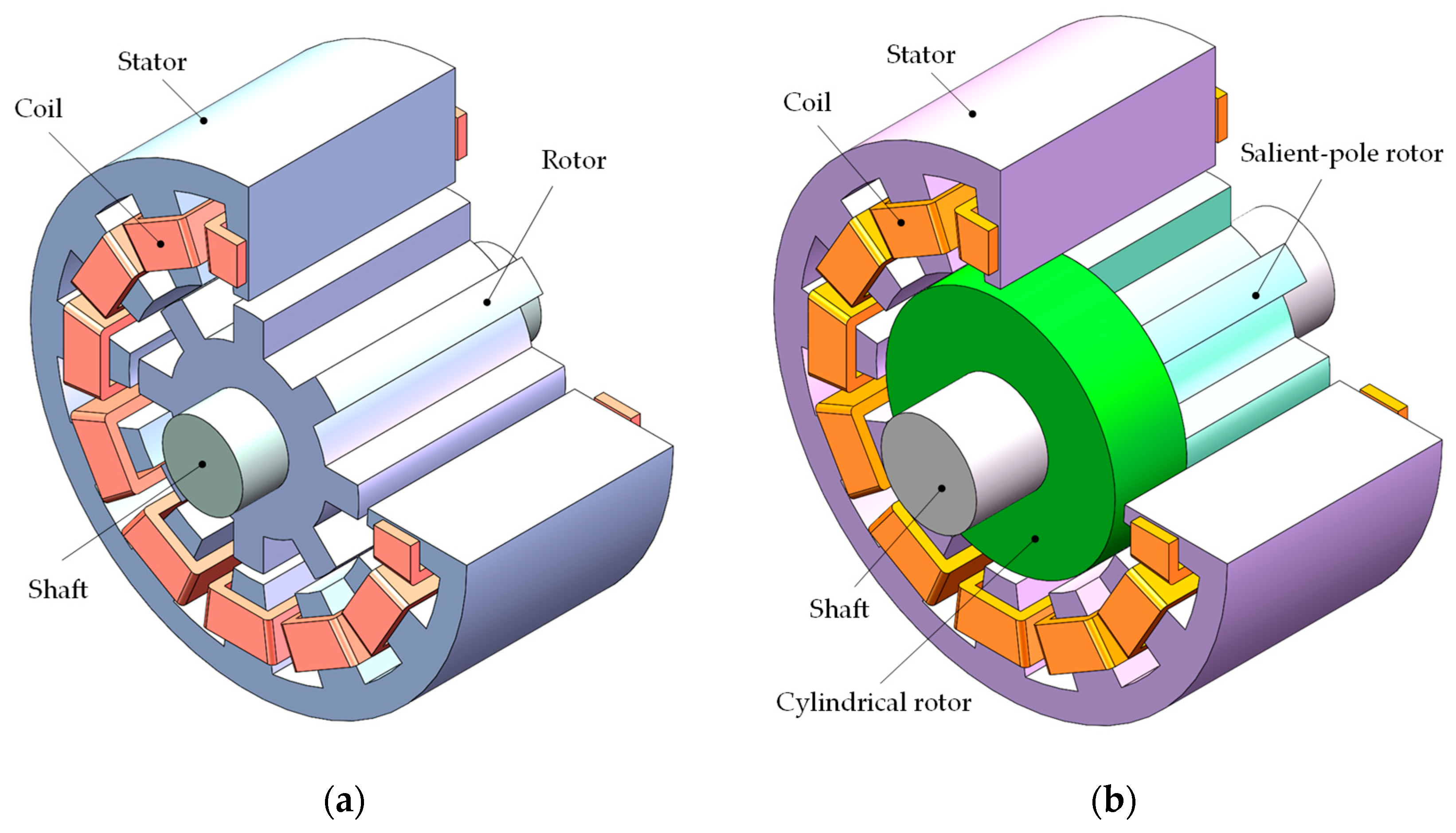
2. Structure and Operating Principle of the 12/8-Pole HBSRM

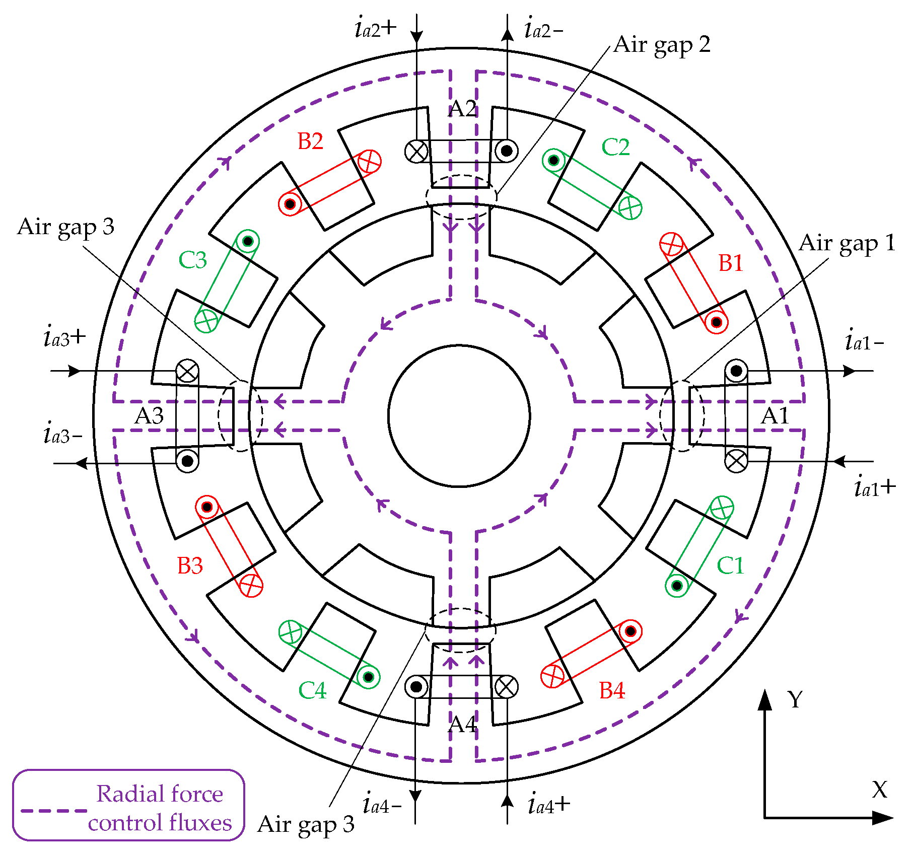
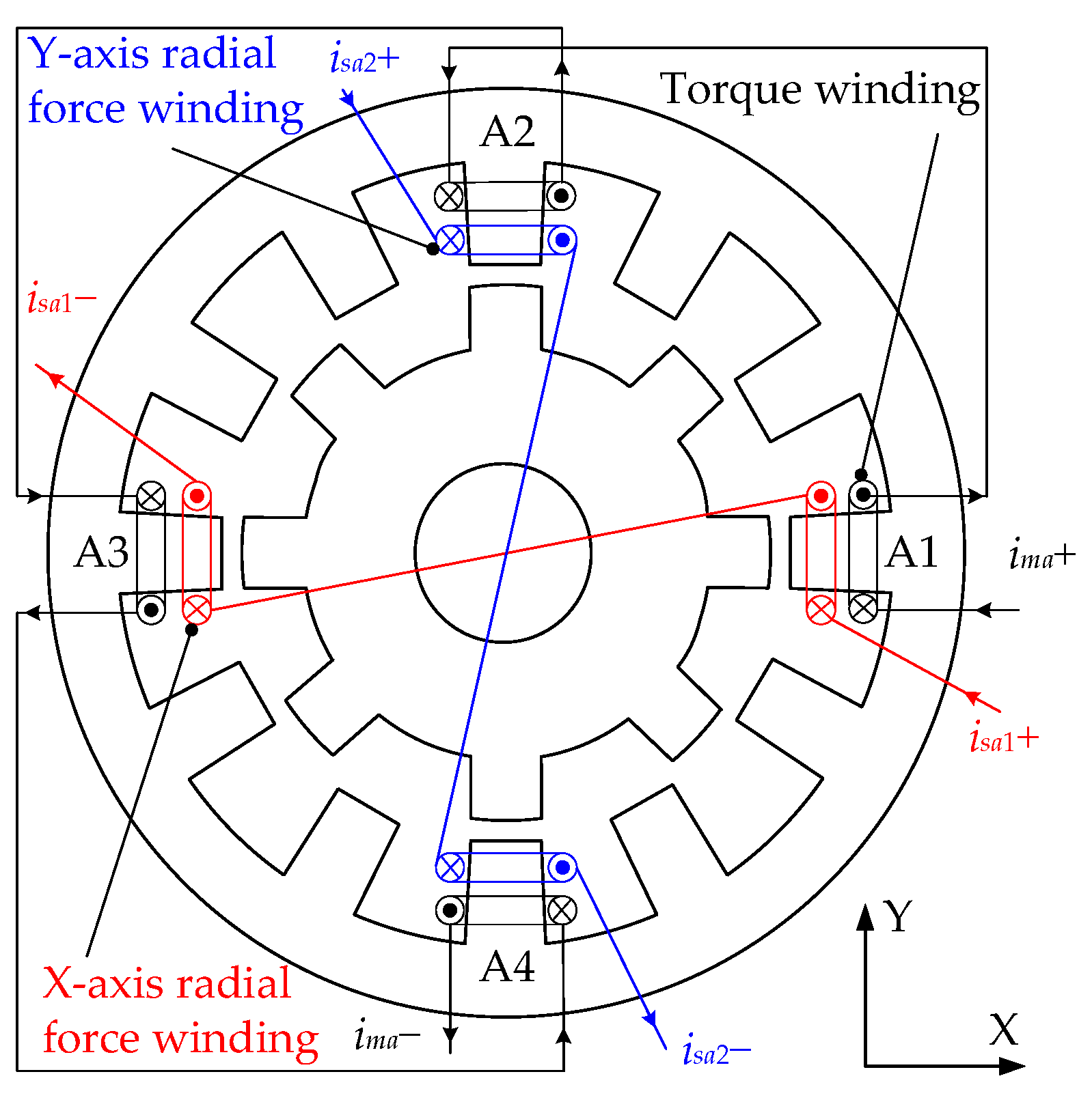
2.1. Structure and Radial Force Production

Different from a traditional 12/8-pole single-winding BSRM, the HBSRM’s hybrid rotor consists of a cylindrical rotor stack and an 8-pole salient rotor stack, and both rotor stacks are closely arranged together, as shown in Figure 1. A coil is wound on each of the twelve stator teeth, and four coils spatially separated by 90° form one phase, phase A, B and C, respectively.
Figure 2 shows three-phase winding configurations and radial force control fluxes of the 12/8-pole HBSRM. Coils on poles A1, A2, A3 and A4 are set to A1-phase, A2-phase, A3-phase and A4-phase, and they together constitute the A-phase. Moreover, currents in phases A1, A2, A3 and A4 are independently controlled to produce two radial forces in the X- and Y-axis directions, and at the same time a positive or negative torque will be generated at different rotor angular positions. Coils on poles B1, B2, B3 and B4 are connected in parallel to construct the B-phase, whereas coils on poles C1, C2, C3 and C4 are connected in parallel to form the C-phase. When phases B and C are excited in turn at the rising regions of the respective phase inductance, there will only be a positive torque and no radial force by the currents in phases B or C.
The radial force control fluxes produced by the A-phase are displayed as the purple dashed line in Figure 2; it is a four-pole magnetic flux and alternately distributed. When the current ia1 in the A1-phase is greater than the current ia3 in the A3-phase, the control flux in air gap 1 will be more than that in air gap 3, so there is a positive radial force acting on the shaft in the X-axis direction. In contrast, if the current ia1 is less than the current ia3, a negative radial force will be produced in the X-axis direction. Similarly, the currents ia2 in the A2-phase and ia4 in the A4-phase are controlled independently, a positive or negative radial force in the Y-axis direction can also be generated. Therefore, a required radial force can be produced by reasonably controlling these four currents in A-phase windings. The rotor angular position θ is defined as θ = 0 at the aligned position of the A-phase, and the rotor angular position θ of Figure 2 is 0.

2.2. Analysis of A-Phase Full-Period Levitation Operations

To simplify the magnetic circuit analysis of the HBSRM discussed in this paper, based on radial force and torque distributions, it is divided into two parts, a 12-pole RMB and a 12/8-pole BSRM. The 12-pole RMB only produce radial forces, and the 12/8-pole BSRM can generate torques and radial forces simultaneously. Two 2D finite element analyses (FEAs) are carried out using the parameters of the prototype shown in Table 1, and magnetic flux distributions of two equivalent parts at the position of θ = −7.5° are shown in Figure 3.
In radial force analysis, the currents in four windings of phase A are respectively set as follows: ia1 = 4 A, ia2 = 2 A, ia3 = 0, and ia4 = 2 A, and a positive radial force in the X-axis direction is generated at this time, as shown in Figure 4. In a traditional SRM, the smaller magnetic permeance near the unaligned positions results in very low radial force generations at these positions, such as the calculated radial forces in the two intervals [−22.5°, −15°] and [15°, 22.5°] in Figure 4, and thus there is a suspended dead zone in this motor. The radial force in the HBSRM can be considered as the sum of the BSRM and RMB parts, and the RMB has a continuous and large radial force at any rotor angular position, so the HBSRM provides a significant increase in radial forces and may eliminate the suspended dead zones in a conventional BSRM, as shown in Figure 4. For traditional 12/8-pole single-winding BSRMs, due to the levitation dead zone at some rotor angular positions of each phase, as shown in Figure 4, a control strategy of three-phase intermittent excitation on turn is forced to be utilized to generate a continuous required radial force. This results in the four coils in each phase of this motor being needed to be individually excited, which in turn requires a half-bridge power circuit for each coil, ultimately increasing the costs of the controller and limiting the range of applications.
Based on the principle of full-cycle levitation operation using the A-phase to generate radial forces, the power converter topology used for the 12/8-pole single-winding HBSRM is shown in Figure 5. The number of power converters and power devices required for three types of 12/8-pole BSRMs is shown in Table 2. Compared to conventional single- and double-winding structures, the number of power switches required for the 12/8-pole HBSRM in this paper is significantly reduced, by 12 and 6, respectively; the drive circuits and digital control resources required for this bearingless motor are also considerably decreased; thus, all of these help to further reduce its controller costs and improve system reliability.
Figure 6 shows three-phase inductances, currents and torque distributions of the 12/8-pole HBSRM presented in this paper. For a 12/8-pole BSRM, one rotor position cycle angle is 45° and divided into six regions, such as Sectors I–VI. In a traditional SRM, each phase is excited sequentially in the rising regions of phase inductance to generate positive torques. However, in the presented HBSRM, phase A is excited all the time to generate a continuous radial force, which results in a negative torque that will be generated in the decreasing regions of A-phase inductance. Table 3 shows three-phase torque contributions in six sections for the 12/8-pole HBSRM with A-phase full-period suspension, where La, Lb and Lc indicate the inductance of the A-, B- and C-phase windings, respectively; Ta, Tb and Tc represent the instantaneous torques generated when phases A, B and C are individually excited, respectively, and Tsum is the instantaneous total torque.
As shown in Figure 6 and Table 3, when the rotor angular position changes from Sector I to VI, the total torque of the 12/8-pole HBSRM may be generated by one, two or three phases. In addition, there are two radial forces that need to be controlled simultaneously. Therefore, it is necessary to establish accurate mathematical models of radial forces and torques in order to calculate and assign their required values in each sector.

3. Mathematical Models of the Radial Force and Torque

For a 12/8-pole HBSRM with one-phase full-cycle suspension, there are five mathematical expressions to be derived: the X-axis radial force Fx, the Y-axis radial force Fy, the torque Ta generated by the four currents ia1ia4 of phase A, the torques Tb and Tc produced by the B-phase current ib, and the C-phase current ic, respectively. In this paper, the mathematical models of the radial force and torque of a 12/8-pole HBSRM are derived by combining its equivalent magnetic circuit and the virtual displacement method. In the derivation, the 12/8-pole HBSRM is divided into a 12-pole RMB part and a 12/8-pole BSRM part in order to simplify this motor’s magnetic circuit analysis and facilitate modelling.
The brief derivation may be described as follows: Firstly, the equivalent magnetic circuit and the air-gap permeance of phase A are established. Then, the magnetic circuit equation is solved to obtain expressions for the A-phase inductance, which in turn establishes its magnetic energy storage. Moreover, the radial forces Fx and Fy can be obtained by solving the derivative of the magnetic energy storage with respect to the respective radial displacement, and the torque Ta may also be derived by calculating the derivative of the magnetic energy storage with respect to the rotor angular position. Similarly, the torques Tb and Tc can also be written directly with reference to the formula of Ta. The difficulty in modelling the radial force and torque for this bearingless motor structure is the resolution of the fringe flux and the derivation of the air-gap permeance, and the detailed procedure is described in [23].
In this paper, the X-axis radial force Fx and the Y-axis radial force Fy of the 12/8-pole single-winding HBSRM are directly given as
F x = K f θ N 2 8 i a 1 + i a 2 + i a 3 + i a 4 i a 1 i a 3 F y = K f θ N 2 8 i a 1 + i a 2 + i a 3 + i a 4 i a 2 i a 4
K f θ = μ 0 h f r π 6 l 0 2 + 2 μ 0 h t r π / 12 θ l 0 2 + 8 μ 0 h t r θ l 0 + 2 θ r l 0 l 0 + θ r 2 l 0 + π θ r ,   0 θ π 12 μ 0 h f r π 6 l 0 2 + 8 μ 0 h t r 2 l 0 2 + r π 2 / 12 l 0 + 2 r θ π / 12 π / 6 θ l 0 + r θ π / 12 2 l 0 + π r θ π / 12 + l 0 + 2 r π / 6 θ θ π / 12 l 0 + r π / 6 θ 2 l 0 + π r π / 6 θ , π 12 < θ π 8
where Kf(θ) is the radial force coefficient, N is the number of turns of a coil, μ0 is the air permeability, ht is the stack length of the salient rotor, hf is the axial length of the cylindrical rotor, r is the rotor radius, and l0 is the average length of the air gap.
The A-phase torque Ta of the 12/8-pole single-winding HBSRM can be expressed as
T a = J t θ N 2 8 i a 1 + i a 2 + i a 3 + i a 4 2 + 2 i a 1 i a 3 2 + 2 i a 2 i a 4 2
J t θ = 2 μ 0 h t r l 0 2 r θ + π / 12 l 0 r θ + π / 12 2 l 0 π r θ + π / 12 l 0 + 2 r θ + π / 6 l 0 + r θ + π / 6 2 l 0 + π r θ + π / 6 , π 8 θ < π 12 μ 0 h t r l 0 2 μ 0 h t r l 0 2 θ r l 0 θ r 2 l 0 π θ r ,   π 12 θ < 0 μ 0 h t r l 0 + 2 μ 0 h t r l 0 + 2 θ r l 0 + θ r 2 l 0 + π θ r ,   0 θ π 12 2 μ 0 h t r l 0 + 2 r θ π / 12 l 0 + r θ π / 12 2 l 0 + π r θ π / 12 + l 0 + 2 r π / 6 θ l 0 + r π / 6 θ 2 l 0 + π r π / 6 θ , π 12 < θ π 8
where Jt(θ) is the torque coefficient, and then the torques Tb and Tc can also be directly obtained by
T b = J t θ + π / 12 N 2 / 8 i b 2 T c = J t θ π / 12 N 2 / 8 i c 2
Figure 7 shows the calculated results of radial force and torque coefficients using the parameters of the prototype shown in Table 1. It can be found from Figure 7 that the mathematical models of radial forces and torques for the 12/8-pole HBSRM derived in the paper have a good accuracy, and the expressions for radial forces and torques are continuous at all the rotor angular positions.
In control, to reduce the number of current variables to be solved, combined with the equivalent principle of magnetomotive forces, the four coils of phase A can be equivalent to three windings: the torque winding, the X-axis radial force winding and the Y-axis radial force winding. The torque winding consists of four torque coils connected in series, and two radial force coils in the X- or Y-axis direction are connected in series to form the X- or Y-axis radial force winding, respectively. At this moment, the bearingless motor is converted from a single-winding structure to a double-winding structure, as shown in Figure 8.
Based on the principle of equivalent magnetomotive force, the relationship between single- and double-winding structures can be expressed as
N m i m a = 1 4 N i a 1 + i a 2 + i a 3 + i a 4 N b i s a 1 = 1 2 N i a 1 i a 3 N b i s a 2 = 1 2 N i a 2 i a 4
where ima is the current in the torque winding of A-phase, isa1 is the current in the X-axis radial force winding of A-phase, isa2 is the current in the Y-axis radial force winding of A-phase, Nm is the number of turns of a torque coil, and Nb is the number of turns of a radial force coil.
Moreover, the A-phase torque and radial force can be rewritten as
F x = K f ( θ ) N m N b i m a i s a 1 F y = K f ( θ ) N m N b i m a i s a 2
T a = J t ( θ ) 2 N m 2 i m a 2 + N b 2 i s a 1 2 + N b 2 i s a 2 2

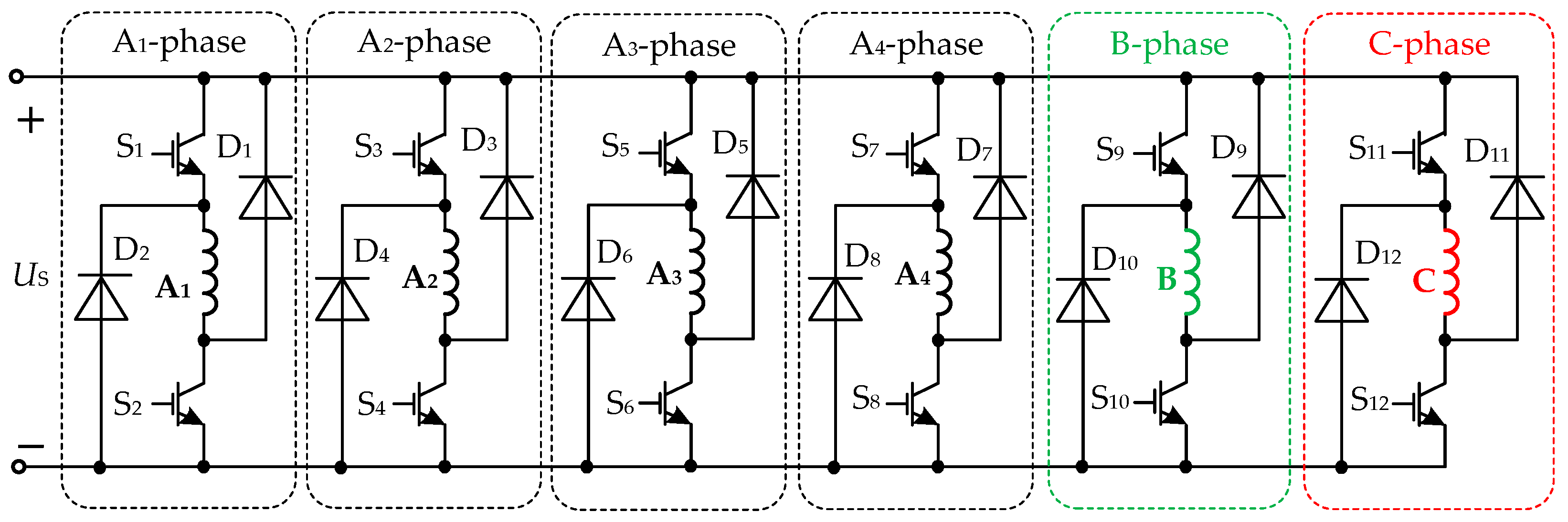
4. Control Strategy and Simulation Analysis

4.1. Control Strategy

Figure 9 is the control block diagram of the 12/8-pole single-winding HBSRM with A-phase full-period suspension. The deviation signal of the given speed n* and the real-time speed n is transmitted to the PI controller, and its output is the reference value of the instantaneous total torque Tsum*. The difference between the reference radial displacement and the real-time displacement is transmitted to the respective PID controller to obtain the needed radial forces in the two mutually perpendicular directions, such as the X-axis instantaneous radial forces Fx* and the Y-axis instantaneous radial forces Fy*. Based on the real-time rotor angular position θ, judge which sector the rotor is in, and then the constraint equations for the corresponding sectors can be obtained. Moreover, the three given values Fx*, Fy*, Tsum* and the constraint formulae in corresponding sectors are fed into a three-phase current calculator, which has outputs of the given currents ima*, isa1*, isa2*, ib* or ic*. Further, three currents ima*, isa1* and isa2* are transformed by the double-single winding conversion to obtain the four given values of A-phase currents ia1*, ia2*, ia3* and ia4*. Finally, the current chopping control is independently applied to these three phases. In addition, when the motor is running at different speeds, the switching angle of the B- or C-phase can be also adjusted in real time to increase the output torque performance.
It can be seen from Figure 9 and Table 3 that there are three given values, Fx*, Fy* and Tsum*, in the control scheme, but the number of unknown currents and the unknown variables to be calculated vary in the six sectors. Sectors I, III, IV and VI require one current constraint equation, Sector V needs two constraint formulae, and no constraint expression is needed in Sector II, so matching current constraint equations need to be designed in each sector.
In Sector I or III, phase A and the other phase (B or C) together produce a positive torque. Based on the principle of single-double winding conversion and combining Equation (6), a current constraint formula for Sector I or III is developed as
N m i m a * = N i b * / 4   Sector   I N m i m a * = N i c * / 4         Sector   III
It can be found from Equation (9) that, when ia1 = ia2 = ia3 = ia4 and N = Nm, currents in four coils of phase B or C are equal to that of phase A, which helps to keep the output power of each phase balanced.
In Sectors IV–VI, phase A generates a negative torque, and it is necessary to increase the current in phase B or C to supplement the negative torque produced by phase A to keep the total output torque smooth. At this point, A-phase current should meet the minimum requirements for radial force generation and then produces as little negative torque as possible. Based on Equations (7) and (8), it can be obtained as
2 F x * 2 + F y * 2 / K f θ 2 = 2 N m 2 i m a * 2 · N b 2 i s a 1 * 2 + i s a 2 * 2 T a * / J t ( θ ) = 2 N m 2 i m a * 2 + N b 2 i s a 1 * 2 + i s a 2 * 2
Thus, it can be seen from Equation (10) that, when the bearingless motor operates from Sectors IV to VI, the minimum possible negative torque of phase A can be obtained if it is satisfied as follows:
2 N m i m a * = N b i s a 1 * 2 + i s a 2 * 2
In Sector V, the B- and C-phase together produce a positive torque; to reduce calculations in control, the second constraint is that both phase currents are equal, i.e., ib* = ic*. Current constraint equations within six sectors are summarized in Table 4. Moreover, combined with Equations (5)–(8) and current constraint equations in Table 4, the given values of three-phase currents can be calculated as shown in Table A1 of Appendix A.

4.2. Simulation Analysis

In order to validate the presented control scheme, a simulation of the 12/8-pole HBSRM control system is performed using Matlab/Simulink. The parameters of the prototype are shown in Table 1, and its rated speed, rated power and rated voltage are 20,000 rpm, 1.5 kW and 310 V, respectively.
Figure 10 shows the simulated results of a 12/8-pole single-winding BSRM at a speed of 1000 rpm using a conventional control scheme of single phase excitation, where the parameters of the BSRM part of the prototype are used, and Fx* = 150 N, Fy* = 100 N and the reference average torque Tav* = 0.8 Nm. Fax, Fbx and Fcx represent the X-axis radial forces generated independently by the A, B and C phase currents. Similarly, Fay, Fby and Fcy are the Y-axis radial forces. Due to the use of average torque control in the speed loop and an excitation width of only 15° per phase, there is a very large torque pulsation, and the maximum change in torque output is about 0.67 Nm when the conventional control scheme is used for this bearingless motor. In addition, it can also be known from Figure 10 that there is a dead zone in the radial force output during excitation phase change because of the desired current not being able to be built up quickly enough.
Figure 11 shows the simulated results of the 12/8-pole single-winding HBSRM at a speed of 1000 rpm, where Fx* = 150 N, Fy* = 100 N and Tsum* = 0.8 Nm. It can be seen from Figure 11 that the two radial forces and the total torque are essentially the same as the respective given values, and all three of them have a good output. As a result of the one-phase full-period levitation control for the HBSRM, the levitation dead zone during phase change due to the limited current rate of change found in the traditional control scheme for a 12/8-pole BSRM, as shown in Figure 10, has also been eliminated.
The simulation results when the bearingless motor is running at the rated speed of 20,000 rpm are shown in Figure 12. At this moment, due to the increase in the back electromotive force, the rate of change of each phase current becomes smaller, and then the real-time tracking and chopping control of currents in three-phase windings becomes not very effective; ultimately, the control accuracy of the two suspended forces and the total torque is also reduced. It can be noted from Figure 12 that, despite the increase in radial force fluctuations, there is no dead zone of suspended force production. In addition, the given total torque Tsum* and the real-time average torque Tav are 0.8 Nm and 0.75 Nm; the error between the two is less than 6.5%, which is acceptable at such high operating speeds.
In order to verify the interaction between the two-control channels of radial force and torque, the radial force and torque mutation is simulated while this motor working at a speed of 10,000 rpm, as shown in Figure 13. In simulation, the X-axis radial force changes suddenly between 150 N and 190 N, the Y-axis radial force varies sharply between 100 N and 140 N, and the total torque changes abruptly between 0.8 Nm and 1.2 Nm. The simulation results show that, when radial force mutations happen, the required radial force can be quickly established and precisely controlled, with basically no impact on the torque channel; similarly, while a sudden change in torque occurs, the output torque can also be well tracked and controlled, with basically no influence on the radial force channel as well. Therefore, it can be obtained from Figure 13 that the radial force channel and the torque channel of the 12/8-pole HBSRM with one-phase full-period suspension almost do not affect each other under the presented control strategy.

5. Conclusions

The 12/8-pole single-winding HBSRM, due to its hybrid rotor consisting of a salient stack and a cylindrical stack, can produce a required radial force to suspend its shaft at any rotor angular position. A single-phase full-cycle levitation control method is proposed for the HBSRM in this paper. The HBSRM with one-phase full-period suspension requires only half the number of power devices used in a traditional 12/8-pole single-winding BSRM, and in turn needs significantly less digital resources and auxiliary drive circuits, which will reduce controller costs and lower the risk of power converter failures. Simulation results demonstrate that the radial force in both directions can be stably controlled with good torque output performance, and the levitation dead zone during phase change usually found in traditional BSRMs adopting a control strategy in which each phase generates suspended forces on turn can also be eliminated. In addition, the radial force and torque mutation simulations show that both radial force and torque control channels have no effect on each other. Further, it should be noted that the method presented in this paper is also applicable to the co-excitation of a 4-pole or 8-pole RMB and a 12/8-pole SRM using six asymmetrical half-bridge power convertors, and only requires that the four torque coils in one phase of the SRM be connected in series with each of the four radial force windings in the RMB.

Author Contributions

Conceptualization, Z.L.; methodology, Z.L. and X.W.; validation, Z.L., X.W., Y.Y. and C.L.; writing—original draft, Z.L., Y.Y. and W.Z.; writing—review and editing, Z.L., C.L. and X.W.; funding acquisition, Z.L. and W.Z.; data curation, X.W. and W.Z. All authors have read and agreed to the published version of the manuscript.

Funding

This research was supported in part by the National Natural Science Foundation of China under grant 52377061, 52007086, in part by the Opening Foundation of Key Laboratory of Special Machine and High Voltage Apparatus under grant KFKT202102, in part by the Joint Opening Foundation of National Rare Earth Permanent Magnet Motor Engineering Technology Research Center of Shenyang University of Technology under grant 2022-KF-24-03, and in part by the Scientific Foundation of Nanjing University of Posts and Telecommunications under grant NY222146.

Data Availability Statement

The raw data supporting the conclusions of this article will be made available by the authors, without undue reservation.

Conflicts of Interest

The authors declare no conflicts of interest.

Appendix A

Table A1. Results of three-phase current calculations.
SectorsResults of Current CalculationsSectorsResults of Current Calculations
I i m a * = 1 2 N m T s u m * ( J t ( θ ) + J t θ + π / 12 ) + T s u m * 2 ( J t ( θ ) + J t θ + π / 12 ) 2 8 J t ( θ ) ( F x * 2 + F y * 2 ) ( J t ( θ ) + J t θ + π / 12 ) K f θ 2 i s a 1 * = 2 F x * K f θ N b / T s u m * ( J t ( θ ) + J t θ + π / 12 ) + T s u m * 2 ( J t ( θ ) + J t θ + π / 12 ) 2 8 J t ( θ ) ( F x * 2 + F y * 2 ) ( J t ( θ ) + J t θ + π / 12 ) K f θ 2 i s a 2 * = 2 F y * K f θ N b / T s u m * ( J t ( θ ) + J t θ + π / 12 ) + T s u m * 2 ( J t ( θ ) + J t θ + π / 12 ) 2 8 J t ( θ ) ( F x * 2 + F y * 2 ) ( J t ( θ ) + J t θ + π / 12 ) K f θ 2 i b * = 2 N T s u m * ( J t θ + J t θ + π / 12 ) + T s u m * 2 ( J t θ + J t θ + π / 12 ) 2 8 J t ( θ a ) ( F x * 2 + F y * 2 ) ( J t θ + J t θ + π / 12 ) K f θ 2 IV i m a * = 1 N m F x * 2 + F y * 2 2 K f θ i s a 1 * = F x * K f θ N b / F x * 2 + F y * 2 2 K f θ i s a 2 * = F y * K f θ N b / F x * 2 + F y * 2 2 K f θ i c * = 2 N 2 2 T s u m * K f θ + 8 J t ( θ ) F x * 2 + F y * 2 J t θ π / 12 2 K f θ
II i m a * = 1 2 N m T s u m * J t ( θ ) + T s u m * 2 J t ( θ ) 2 8 ( F x * 2 + F y * 2 ) K f θ 2 i s a 1 * = 2 F x * K f θ N b / T s u m * J t ( θ ) + T s u m * 2 J t ( θ ) 2 8 ( F x * 2 + F y * 2 ) K f θ 2 i s a 2 * = 2 F y * K f θ N b / T s u m * J t ( θ ) + T s u m * 2 J t ( θ ) 2 8 ( F x * 2 + F y * 2 ) K f θ 2 V i m a * = 1 N m F x * 2 + F y * 2 2 K f θ i s a 1 * = F x * K f θ N b / F x * 2 + F y * 2 2 K f θ i s a 2 * = F y * K f θ N b / F x * 2 + F y * 2 2 K f θ i b * = i c * = 2 N 2 2 T s u m * K f θ + 8 J t ( θ ) F x * 2 + F y * 2 J t θ π / 12 + J t θ + π / 12 2 K f θ
III i m a * = 1 2 N m T s u m * ( J t ( θ ) + J t θ π / 12 ) + T s u m * 2 ( J t ( θ ) + J t θ π / 12 ) 2 8 J t ( θ ) ( F x * 2 + F y * 2 ) ( J t ( θ ) + J t θ π / 12 ) K f θ 2 i s a 1 * = 2 F x * K f θ N b / T s u m * ( J t ( θ ) + J t θ π / 12 ) + T s u m * 2 ( J t ( θ ) + J t θ π / 12 ) 2 8 J t ( θ ) ( F x * 2 + F y * 2 ) ( J t ( θ ) + J t θ π / 12 ) K f θ 2 i s a 2 * = 2 F y * K f θ N b / T s u m * ( J t ( θ ) + J t θ π / 12 ) + T s u m * 2 ( J t ( θ ) + J t θ π / 12 ) 2 8 J t ( θ ) ( F x * 2 + F y * 2 ) ( J t ( θ ) + J t θ π / 12 ) K f θ 2 i c * = 2 N T s u m * ( J t ( θ ) + J t θ π / 12 ) + T s u m * 2 ( J t ( θ ) + J t θ π / 12 ) 2 8 J t ( θ ) ( F x * 2 + F y * 2 ) ( J t ( θ ) + J t θ π / 12 ) K f θ 2 VI i m a * = 1 N m F x * 2 + F y * 2 2 K f θ i s a 1 * = F x * K f θ N b / F x * 2 + F y * 2 2 K f θ i s a 2 * = F y * K f θ N b / F x * 2 + F y * 2 2 K f θ i b * = 2 N 2 2 T s u m * K f θ + 8 J t ( θ ) F x * 2 + F y * 2 J t θ + π / 12 2 K f θ

References

  1. Huang, L.R.; Zhu, Z.Q.; Feng, J.H.; Guo, S.Y.; Li, Y.F.; Shi, J.X. Novel current profile of switched reluctance machines for torque density enhancement in low-speed applications. IEEE Trans. Ind. Electron. 2020, 67, 9623–9634. [Google Scholar] [CrossRef]
  2. Ghani, A.; Khalid, H.A.; Rehman, H. Saliency ratio-based torque enhancement of switched reluctance motors for electric bikes. Energies 2023, 16, 7320. [Google Scholar] [CrossRef]
  3. Sayed, E.; Abdalmagid, M.; Pietrini, G.; Sa’adeh, N.M.; Callegaro, A.D.; Goldstein, C.; Emadi, A. Review of electric machines in more-/hybrid-/turbo-electric aircraft. IEEE Trans. Transp. Electr. 2021, 7, 2976–3005. [Google Scholar] [CrossRef]
  4. Liaw, C.M.; Jhou, P.H.; Yang, C.W. Switched-reluctance motor drive for more electric aircraft with energy storage buffer. IEEE Trans. Aerosp Electron Syst. 2023, 59, 7423–7439. [Google Scholar] [CrossRef]
  5. Charl, P.; Winston, H.; Earl, G. Magnetic bearing controls for a high-speed, high-power switched reluctance machine (SRM) starter/generator. In Proceeding of SAE Power Systems Conference, San Diego, CA, USA, 31 October–2 November 2000; Society of Automotive Engineers: San Diego, CA, USA, 2000; pp. 3665–3671. [Google Scholar]
  6. Yang, R.; He, Z.Q.; Sugita, N.; Shinshi, T. Low-cost and compact disposable extracorporeal centrifugal blood pump utilizing a homopolar bearingless switched reluctance slice motor. IEEE Access 2023, 11, 24353–24366. [Google Scholar] [CrossRef]
  7. Yang, F.; Sun, Y.K.; Yuan, Y.; Huang, Y.H. A 5-degrees of freedom hybrid excitation bearingless motor for vehicle flywheel battery. Electron. Lett. 2021, 57, 909–911. [Google Scholar] [CrossRef]
  8. Gao, H.W.; Liu, Z.D.; Wang, X.N.; Li, D.Y.; Zhang, T.; Yu, J.H.; Wang, J.B. A novel motor structure with extended particle swarm optimization for space robot control. Sensors 2023, 23, 4126. [Google Scholar] [CrossRef]
  9. Takemoto, M.; Chiba, A.; Fukao, T. A method of determining advanced angle of square-wave currents in a bearingless switched motor. IEEE Trans. Ind. Applicat. 2001, 37, 1702–1709. [Google Scholar] [CrossRef]
  10. Takemoto, M.; Chiba, A.; Akagi, H.; Fukao, T. Radial force and torque of a bearingless switched reluctance motor operating in a region of magnetic saturation. IEEE Trans. Ind. Applicat. 2004, 40, 103–112. [Google Scholar] [CrossRef]
  11. Hao, Z.Y.; Zhu, T.; Cao, X.; Yu, Q.; Zhang, Q.Y. Direct displacement control for single-winding bearingless switched reluctance motor. IEEE Access 2020, 8, 211269. [Google Scholar] [CrossRef]
  12. Lo, Y.K.; Chiu, H.J.; Song, T.H. Elimination of voltage imbalance between the split capacitors in three-phase half-bridge switched-mode rectifiers. In Proceedings of the 4th IEEE International Conference on Power Electronics and Drive Systems, Denpasar, Indonesia, 22–25 October 2001; pp. 163–165. [Google Scholar]
  13. Yang, G.; Deng, Z.Q.; Cao, X.; Wang, X.L. Optimal winding arrangements of a bearingless switched reluctance motor. IEEE Trans. Power Electr. 2008, 23, 3056–3066. [Google Scholar] [CrossRef]
  14. Chen, L.; Hofmann, W. Speed regulation technique of one bearingless 8/6 switched reluctance motor with simpler single winding structure. IEEE Trans. Ind. Electron. 2012, 59, 2592–2600. [Google Scholar] [CrossRef]
  15. Yang, Y.F.; Zhang, G.X.; Wang, F.G. Design and analysis of a new bearingless switched reluctance motor. Int. J. Appl. Electrom. 2023, 71, 91–102. [Google Scholar] [CrossRef]
  16. Zhu, T.; Cao, X.; Yu, Q.; Deng, Z.Q.; Hao, Z.Y. Direct torque control with phase commutation optimization for single-winding bearingless switched reluctance motor. IEEE Trans. Power Electr. 2022, 37, 13238–13249. [Google Scholar] [CrossRef]
  17. Cao, X.; Deng, Z.Q.; Yang, G.; Wang, X.L. Independent control of average torque and radial force in bearingless switched-reluctance motors with hybrid excitations. IEEE Trans. Power Electr. 2009, 24, 1376–1385. [Google Scholar] [CrossRef]
  18. Guan, Z.; Zhang, F.; Ahn, J.W. High speed direct current compensation control for 8/10 bearingless SRM. In Proceeding of the IEEE International Symposium on Industrial Electronics, Hangzhou, China, 28–31 May 2012; pp. 1934–1939. [Google Scholar]
  19. Xu, Z.; Lee, D.H.; Ahn, J.W. Suspending force control of a novel 12/14 hybrid stator pole type BSRM. In Proceeding of the 15th International Conference on Electrical Machines and Systems, Sapporo, Japan, 21–24 October 2012; pp. 1–5. [Google Scholar]
  20. Xu, Z.Y.; Huang, C.; Wang, H.J.; Lee, D.H.; Zhang, F.G. Mathematical model of stepped rotor type 12/14 bearingless switched reluctance motor based on maxwell stress method. Energy Rep. 2023, 9, 556–566. [Google Scholar] [CrossRef]
  21. Zhu, Z.Y.; Jiang, Y.J.; Zhu, J.; Guo, X. Performance comparison of 12/12 pole with 8/10 and 12/14 pole bearingless switched reluctance machine. Electron. Lett. 2019, 55, 327–329. [Google Scholar] [CrossRef]
  22. Morrison, C.R.; Siebert, M.W.; Ho, E.J. Electromagnetic forces in a hybrid magnetic-bearing switched-reluctance motor. IEEE Trans. Magn. 2008, 44, 4626–4638. [Google Scholar] [CrossRef]
  23. Liu, Z.Y.; Chen, M.; Yang, Y.; Liu, C.Z.; Gao, H. A full-period mathematical model for a hybrid-rotor bearingless switched reluctance motor. Symmetry 2021, 13, 2383. [Google Scholar] [CrossRef]
Figure 1. Three-dimensional schematic of the 12/8-pole single-winding BSRM and HBSRM. (a) BSRM; (b) HBSRM.
Symmetry 16 00369 g001
Figure 2. Three-phase winding configurations and radial force control fluxes of the 12/8-pole HBSRM.
Symmetry 16 00369 g002
Figure 3. Magnetic flux distribution of two equivalent parts. (a) RMB part; (b) BSRM part.
Symmetry 16 00369 g003
Figure 4. Radial force distributions in the 12/8-pole HBSRM.
Symmetry 16 00369 g004
Figure 5. Three-phase power converters of the 12/8-pole HBSRM.
Symmetry 16 00369 g005
Figure 6. Three-phase inductances, currents and torque distributions of the 12/8-pole HBSRM.
Symmetry 16 00369 g006
Figure 7. Comparison of radial force and torque coefficients. (a) Torque coefficient; (b) radial force coefficient.
Symmetry 16 00369 g007
Figure 8. A-phase winding configurations of the 12/8-pole double-winding BSRM.
Symmetry 16 00369 g008
Figure 9. Control block diagram of the 12/8-pole HBSRM with A-phase full-period suspension.
Symmetry 16 00369 g009
Figure 10. Simulated results of the 12/8-pole single-winding BSRM at 1000 rpm using a conventional control scheme. (a) Current; (b) radial force and torque.
Symmetry 16 00369 g010
Figure 11. Simulated results of the 12/8-pole single-winding HBSRM at 1000 rpm. (a) Current; (b) radial force and torque.
Symmetry 16 00369 g011
Figure 12. Simulated results at 20,000 rpm. (a) Current; (b) radial force and torque.
Symmetry 16 00369 g012
Figure 13. Simulated results at 10,000 rpm. (a) Current; (b) radial force and torque.
Symmetry 16 00369 g013
Table 1. Parameters of the prototype.
ParameterValue
Outer diameter of stator105 mm
Inner diameter of stator52.5 mm
Stator yoke6.5 mm
Outer diameter of salient rotor52 mm
Salient rotor yoke6 mm
Shaft diameter25 mm
Stator pole arc angle15°
Salient rotor pole arc angle15°
Number of stator poles12
Number of salient rotor poles8
Number of winding turns60
Number of parallel winding turns2
Length of salient rotor stack75.0 mm
Length of cylindrical rotor stack25.0 mm
Silicon steel sheet grade35DW270
Table 2. Number of power converters and power devices required for the three types of 12/8-pole BSRMs.
Three Types of 12/8-Pole StructuresPower Converters RequiredPower Devices Required
Asymmetric Half-Bridge CircuitsThree-Phase Half-Bridge Circuits Power SwitchesDiodesTotal
Single-winding BSRM120242448
Double-winding BSRM3218624
Single-winding HBSRM in the paper60121224
Table 3. Three-phase torque contributions in six sectors.
SectorsTaTbTcTsum
I++0Tsum = |Ta|+|Tb|
II+00Tsum = |Ta|
III+0+Tsum = |Ta|+|Tc|
IV0+Tsum = −|Ta|+|Tc|
V++Tsum = −|Ta|+|Tb|+|Tc|
VI+0Tsum = −|Ta|+|Tb|
Table 4. Current constraint equations in six sectors.
Sectors T s u m * Given ValuesUnknown Currents No. of ConstraintsCurrent Constraint Equations
I T a * + T b * F x *
F y *
T s u m *
i m a *
i s a 1 *
i s a 2 *
i b * 1 N m i m a * = N i b * / 4
II T a * 0
III T a * + T c * i c * 1 N m i m a * = N i c * / 4
IV T a * + T c * i c * 1 2 N m i m a * = N b i s a 1 * 2 + i s a 2 * 2
V T a * + T b * + T c * i b * , i c * 2 2 N m i m a * = N b i s a 1 * 2 + i s a 2 * 2 , i b * = i c *
VI T a * + T b * i b * 1 2 N m i m a * = N b i s a 1 * 2 + i s a 2 * 2
Disclaimer/Publisher’s Note: The statements, opinions and data contained in all publications are solely those of the individual author(s) and contributor(s) and not of MDPI and/or the editor(s). MDPI and/or the editor(s) disclaim responsibility for any injury to people or property resulting from any ideas, methods, instructions or products referred to in the content.

