Article

Symmetrical Modeling of Physical Properties of Flexible Structure of Silicone Materials for Control of Pneumatic Soft Actuators

1
Institute of General Engineering, Empress Catherine II Saint Petersburg Mining University, 2, 21st Line, Saint Petersburg 199106, Russia
2
Higher School of Cyberphysical Systems & Control, Peter the Great St. Petersburg Polytechnic University, Saint Petersburg 195251, Russia
*
Author to whom correspondence should be addressed.
Symmetry 2024, 16(6), 750; https://doi.org/10.3390/sym16060750
Submission received: 15 May 2024 / Revised: 10 June 2024 / Accepted: 14 June 2024 / Published: 16 June 2024

Abstract

:
With the ongoing advancements in material technology, the domain of soft robotics has garnered increasing attention. Soft robots, in contrast to their rigid counterparts, offer superior adaptability to the environment, enhanced flexibility, and improved safety, rendering them highly suitable for complex application scenarios such as rescue operations and medical interventions. In this paper, a new type of pneumatic software actuator is proposed. The actuator adopts a combination of a soft structure and pneumatic control, which is highly flexible and versatile. By using the flow of gas inside the soft structure, high-precision and flexible motion control is realized. In the design process, the extensibility and adaptability of the structure are considered, so that the actuator can adapt to different working environments and task requirements. The experimental results show that the pneumatic soft actuator exhibits excellent performance in terms of accuracy, response speed, and controllability. This research provides new ideas and methods for the development of the field of pneumatic actuators and has wide application prospects. The main research content of this paper is as follows: first, the soft pneumatic actuator is modeled and simulated, the structure is optimized on the basis of simulation, and finally, the performance of the actuator is tested.

1. Introduction

The use of robots has become indispensable in industrial production and life. Robots in the traditional sense are mainly based on rigid structures. However, traditional rigid-body robots are limited by their own mechanical structure, and their operation has unknown safety risks. They cannot adapt to various complex mission environments [1,2], and there are still many difficulties and challenges in applications with special needs such as military reconnaissance [3], disaster rescue [4], and scientific exploration.
Due to the characteristics of rigid structural materials, robots cannot adapt to changes in complex environments. Robots made of rigid materials have some disadvantages, such as their large size and low safety, which make rigid robots unable to be used in many application scenarios. Therefore, people are in urgent need of developing robots that avoid these shortcomings. Researchers have developed soft robots by imitating soft animals in nature. Soft robots use less or no traditional rigid materials, but instead use moldable materials such as fluids, gels, and shape memory polymers. This material exhibits the same elastic and deformable properties as soft organisms, can withstand large strains, and allows robots to stretch and contract significantly in a variety of different environments. By actively deforming the robot body, its original morphology, structure, and size are changed to adapt to changing environments and perform specific operations. The soft robot makes up for many defects of the rigid body robot and has many irreplaceable advantages [5]:
(1)
In theory, the soft robot has unlimited degrees of freedom, so its own structure is simple, and it is easy to design customized functions;
(2)
Because the soft robot has good compliance, it can adapt to unknown or complex working environments and facilitate smooth progress of detection;
(3)
When in contact with objects, the soft robot can reduce damage to objects and reduce the risk of damage to objects due to improper contact, and it can operate objects of different shapes and sizes;
(4)
In addition, the structural design of the soft robot itself is not complicated, the manufacturing and processing process is relatively simple, the preparation time is short, and the production cost is small.
Currently, the advancement of 3D printing technology and the emergence of intelligent materials, including shape memory alloys (SMAs), shape memory composite materials (SMP), ionic polymer metal composite materials (IPMC), and dielectric elastomers (DEs), have established a solid foundation for the further exploration of soft robotics. Drawing inspiration from the locomotion mechanisms observed in nature [6,7,8], researchers have leveraged the unique structural features of soft organisms in the design of soft robots, enabling them to successfully accomplish specific locomotion tasks. This kind of robot is called a bionic soft robot [9,10].
Because the research on soft robots involves many fields such as materials, biology, and control, its development has faced many difficulties and challenges [11]:
(1)
How to design bionic structures and select intelligent materials to quickly and efficiently process soft robots that meet expected needs [12].
(2)
The most widely used sensors on the market, such as encoders, potentiometers, and force tactile sensors, are not suitable for soft robots. In order to ensure the precise control of software robots, research on new variable sensors has become an urgent task [13,14,15].
(3)
A soft robot is made of flexible materials, and its material properties are non-linearly transformed. Therefore, the traditional rigid robot D-H law does not apply to soft robots. This poses a serious challenge to the theoretical analysis of soft robots, and the establishment of a new modeling method of soft robots has become an urgent difficulty to overcome.
The research on soft robots is not only conducted to make up for the shortcomings of traditional rigid body robots but also to promote the research and development of related disciplines, which have broad application prospects and research significance [16,17,18].
Soft robots are usually composed of elastic materials that can produce large strains, with multiple degrees of freedom and the ability to produce large deformations. In order to adapt to the characteristics of these soft robots, the drive should meet the requirements of high flexibility and low inertia of motion, and usually, the drive is integrated with the body structure of the robot, so the drive and transmission device traditionally used in rigid robots cannot be applied to soft robots. For researchers, in order for soft robots to function and achieve the desired results, choosing the appropriate driving method is the most critical topic in soft robot research [19,20,21]. Through the reading and inductive analysis of the research results on soft robots so far, it can be seen that most of the driving methods are physically driven, and a small part are chemically driven.
Physical drives include gas drives, shape memory alloy drives (SMA), and electroactive polymeric material (EAP) drives. Chemical drive refers to the use of chemical reactions to convert chemical energy into mechanical energy to drive the movement of soft robots. Its typical representative is the internal combustion explosion drive. Each driving method has its own advantages and disadvantages [22,23,24].
In this article, the gas drive method is mainly used to drive the soft gas actuator. The gas drive has the following advantages [25,26,27]:
(1)
The gas drive system has a high-power density, can provide relatively large force and speed, and is suitable for some application scenarios that require a high power output.
(2)
As a driving medium, gas is widely present in nature, such as air, nitrogen, etc., so gas driving has good availability and accessibility. Compared with other driving methods, such as liquids or chemical compounds, gases are easier to obtain and process.
(3)
Gas drives often use compressed gas or fluid as the driving medium. Compared with liquids or chemical compounds, gases are safer when leaking or released and have a smaller impact on the environment. In addition, gas drive usually does not produce harmful substances and meets environmental protection requirements.
(4)
The gas drive system has high flexibility and responsiveness and can quickly adjust and control the flow, pressure, and direction of the gas, so as to achieve precise motion control. This makes the gas drive perform well in applications that require a fast and precise response [28,29].
In this article, first of all, for the design of the pneumatic software actuators, we considered the mutual integration of a flexible structure and pneumatic control. Through the reasonable selection of materials and structural forms, a highly flexible and versatile mechanism design was realized. In the design process, we paid special attention to the extensibility and adaptability of the organization so that it can adapt to different working environments and task needs.
Secondly, we carried out simulation optimization and used computer simulation technology to evaluate and improve the performance of pneumatic software actuators. Through the establishment of a mathematical model, considering factors such as the gas flow, material properties, and mechanism dynamics, system-level simulation analysis and optimization were carried out. Through the feedback and adjustment of simulation results, the design parameters and working characteristics of the mechanism were continuously improved to improve its performance and reliability.
Finally, we conducted a performance test to verify the actual performance of the pneumatic software actuator. Through the construction of an experimental platform, various performance tests were carried out, including the evaluation of indicators such as accuracy and load capacity. The experimental results show that the proposed pneumatic software actuator exhibits excellent performance in various indicators, and the effectiveness of its design and optimization was verified.
Outstanding achievements have been reached in the field of soft robots. For example, the bionic operating assistant designed by Festo in Germany based on the characteristics of an elephant’s trunk can smoothly carry loads. Its pneumatic drive design enables it to perform well in precise operations, which is very useful for material handling and precise operations at disaster relief sites. The positive and negative pressure integrated programmable pneumatic drive system developed by Professor Liao Hongen’s research group at Tsinghua University provides precise and stable air pressure control for soft robots. This system can be used to control the movement of soft robots in complex environments. The Bionic Motion Robot [30] is a lightweight robot with natural movements. This pneumatic lightweight robot has 12 degrees of freedom. The Bionic Motion Robot can act as a third hand in monotonous, repetitive, or even dangerous activities, providing support during assembly processes and relieving the burden on humans. The development prospects of soft robots are very broad, and they have shown great potential and application value in many fields. Because soft robots are soft and biocompatible, they can be used in the medical field, can safely interact and collaborate with humans, and are suitable for assistance, companionship, and education. Soft robots can adapt to complex and narrow environments, so they can perform search and rescue missions in ruins. The team led by Wang Hao and Chen Genliang from Shanghai Jiao Tong University proposed a lightweight and high-strength fabric-based robot/manipulator that breaks through the bottleneck of the mutual constraints between the flexibility and carrying capacity of traditional flexible robots [31]. The research team at the University of California, San Diego, developed a pneumatic soft robot without electronic components, which is controlled by a ring oscillator composed of soft valves [32]. The Yuanzhi team at Shanghai Jiao Tong University optimized the cavity shape and input air pressure of a multi-cavity pneumatic soft robot for a variety of motion modes and designed a multi-degree-of-freedom flexible arm [33]. In this article, the material Dragon Skin 30 was used. In the simulation study of the soft pneumatic gripper, Dragon Skin 30 showed good gripping performance and was able to provide stable gripping force compared with other silicone materials [34]. Multiple simulation models were performed, and the results were compared to obtain a good soft robot structure, which improved the efficiency and capability of the robot.
In summary, this research proposes a new type of pneumatic software actuator through structural design, simulation optimization, and performance testing and verifies its feasibility and advantages. This research result is of great significance to promote the development of the field of pneumatic actuators and provides new technical solutions for related application fields such as robotics, medical equipment, and industrial automation.

2. Materials and Methods

  • Structural design:
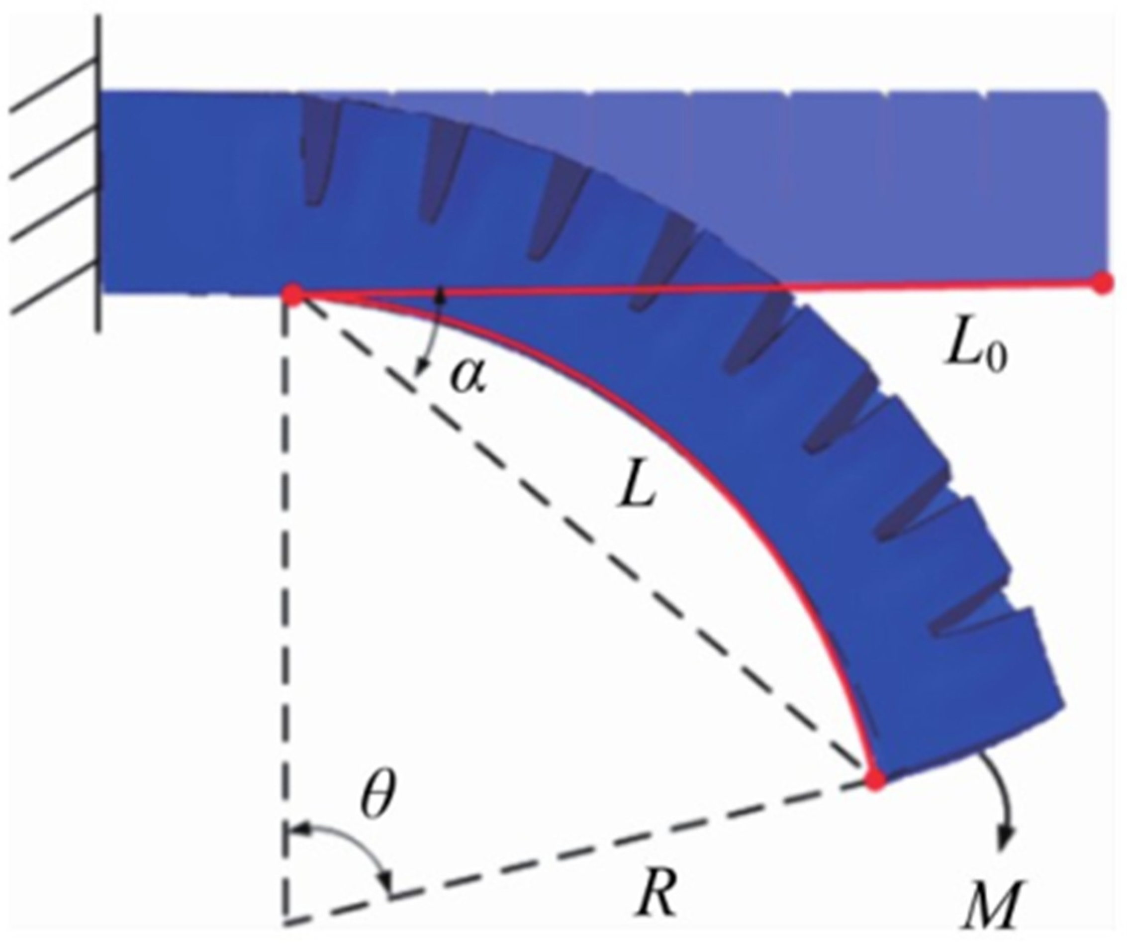
The soft actuator is divided into a drive layer and a restraint layer. The structure is shown in Figure 1 and Figure 2. It consists of 9 serrated air cavities, and the angle between the front ends of each serrated air cavity is 135°. The structural parameters are shown in Table 1. Each air cavity exists independently, and there is a certain distance between the air cavities. When the stable air pressure is input into each air cavity, the cavity walls expand and squeeze each other, causing the actuator to produce a bending moment and resulting in bending deformation, which leads to a greater bending performance than the traditional air cavity.
  • Mathematical modeling:
Under the action of air pressure, the force F acting on the inner surface of the air cavity and the bending moment M of the centripetal force will be generated. According to Euler–Bernoulli’s law, it can be obtained as follows [31,32,33]:
M i E i = 1 R
Among them, the force acting on the inner surface of the air cavity is
F i = p i A i
Ignoring the uneven part of the fingertips, the bending moment generated by the action on the inner surface is
M i = F i h i = p i A i h i
In the formula, the following apply:
p i —the air pressure acting on the inner surface of the air cavity;
A i —the area of the cavity at the cross-section;
h i —the distance from the center of gravity of the cross-section to the center of the neutral surface.
Then, the moment of inertia of the cross-section at the bend, I , is
I = y 2 d A
Since it is difficult to measure θ directly in the experiment, α is used instead of θ . The geometric relationship between the two problems is
α = 1 2 θ
And θ can be expressed as in radians:
θ = L R
Since silicone is a flexible material, expansion and deformation will occur under the action of F i , and the axial tensile length of the actuator L can be expressed as follows:
L = F i L s E A c = p i A i L s E A c
In the formula, the following apply:
E —Young’s modulus of silicone material;
A c —the area of the silicone-filled part at the cross-section;
L s —the sum of the length of a single air cavity and the distance between adjacent air cavities.
Combine Formulas (1) and (3) to obtain the following:
R = E I M i = E I p i A i h i
If Formulas (5)–(7) are combined, the bending angle is expressed as follows:
α = 1 2 θ = L 2 R = L 0 + L 2 R
In the formula, the following apply:
R —the radius of the fan-shaped part under the radian system;
L —the arc length of the fan-shaped part under the radian system;
L 0 —the length of the actuator before the bending deformation occurs is simplified to obtain the relationship between the bending angle α and the input air pressure P as follows:
α = A i L 0 h i 2 E I p i = A i 2 L s h i 2 E 2 I A c p i 2
  • Parameter determination:
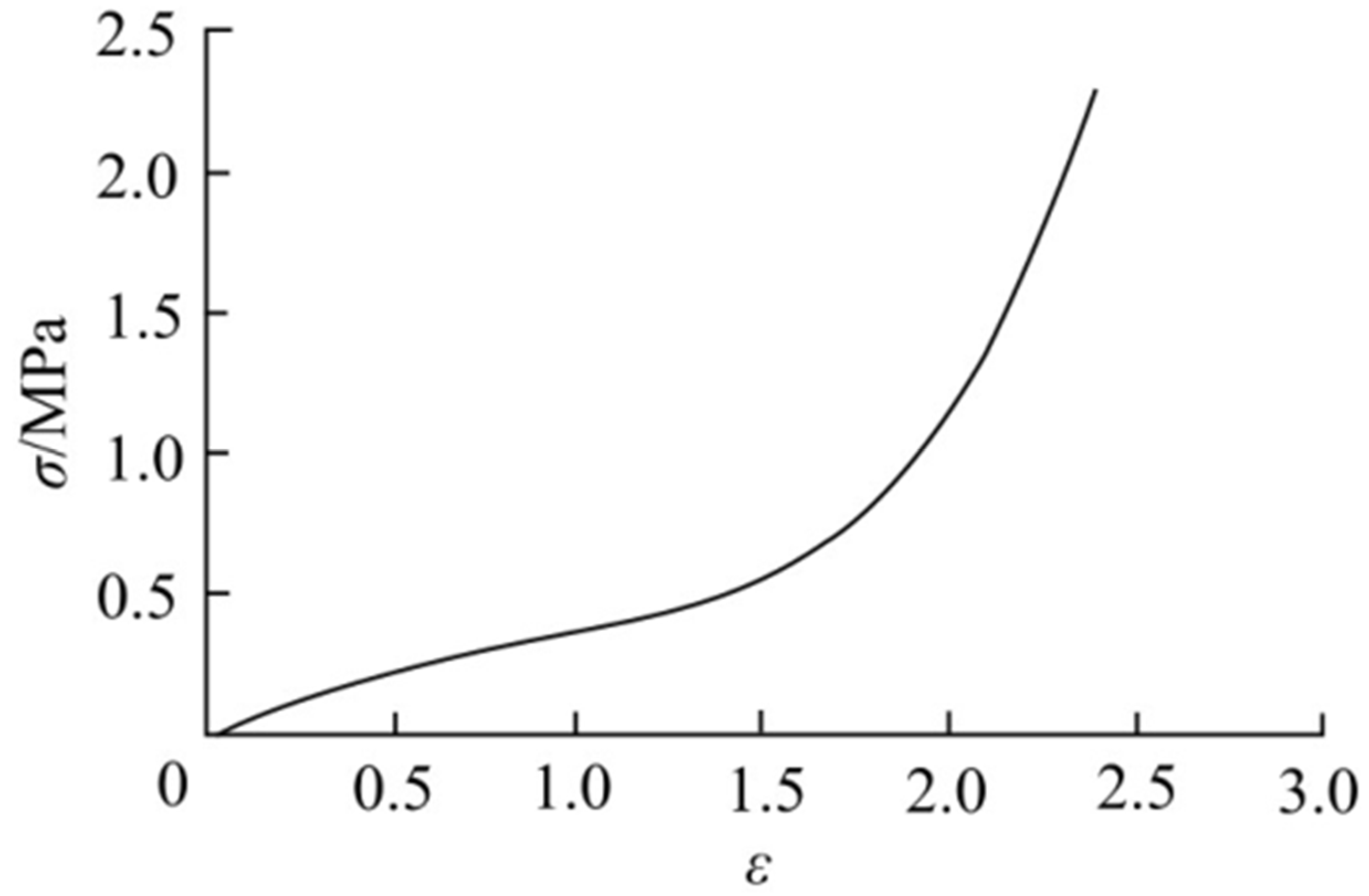
The soft actuator is made of the superelastic material Dragon Skin 30 silicone, which has the characteristics of non-linearity and large deformation when subjected to force deformation [34,35,36]. Therefore, the uniaxial tensile experiment provides real stress and strain data to determine the material properties and selects the QLW-5E electronic tensile tester to measure the parameters.
Dragon Skin 30 Silicone is a high-performance, soft, and stretchable platinum-cured liquid silicone that offers numerous benefits:
(1)
Softness: With a Shore A hardness of 30 A, Dragon Skin 30 Silicone is very soft, similar to human skin.
(2)
High Stretchability: It has extremely high stretchability and can be stretched to many times its original size without breaking, making it ideal for applications that require high elasticity.
(3)
High Strength: Despite its softness, Dragon Skin 30 Silicone also has excellent physical strength and can withstand large pressures and deformations.
(4)
Durability: This silicone has excellent durability and anti-aging properties and can maintain its properties for a long time without degradation.
(5)
Non-Toxic and Odorless: Dragon Skin 30 Silicone material is non-toxic and odorless, making it suitable for applications that come into contact with the human body.
In order to ensure the accuracy of the experiment, three silicone samples were made at different time periods for stretching. The sample size is shown in Figure 3, with a length of 115 mm and a thickness of 25 mm. The length of the stretched part is 33 mm, and the width is 6 mm.
During the stretching process, both ends of the sample are clamped to the upper and lower ends of the tensile testing machine, and the tensile part of the sample is clamped with an extensometer to keep the sample in a natural vertical state. The upper computer is connected to the equipment, and the parameters are set to process the measured load and deformation. The engineering stress is calculated as F / S , where F is the measured load and s is the cross-sectional area of the tensile part of the sample before deformation, and the engineering strain is calculated as L   / L 0 , where L is the deformation variable and L 0 is the length of the tensile part before deformation. After processing, a data set of engineering stress and engineering strain can be obtained, and the stress response can be fitted and plotted. The curve is shown in Figure 4.
  • Simulation optimization of the combination of different factors and parameters:
There are many factors that affect the bending angle of the actuator. In order to compare the influence of different factors on the bending angle, we used the control variable method to simulate and analyze the three factors of air cavity wall thickness, air cavity height, and air cavity spacing. As shown in Figure 5, we have clearly marked each factor.
Through the control variable method, we keep factors other than the factors being studied unchanged in order to observe and analyze the influence of each factor on the bending angle of the actuator separately. By simulating and analyzing different factors, we can obtain the degree of influence of each factor on the bending angle of the actuator under different values. Such an analysis method helps us gain an in-depth understanding of the relationship between different factors and provides a scientific basis for optimizing the design and control.
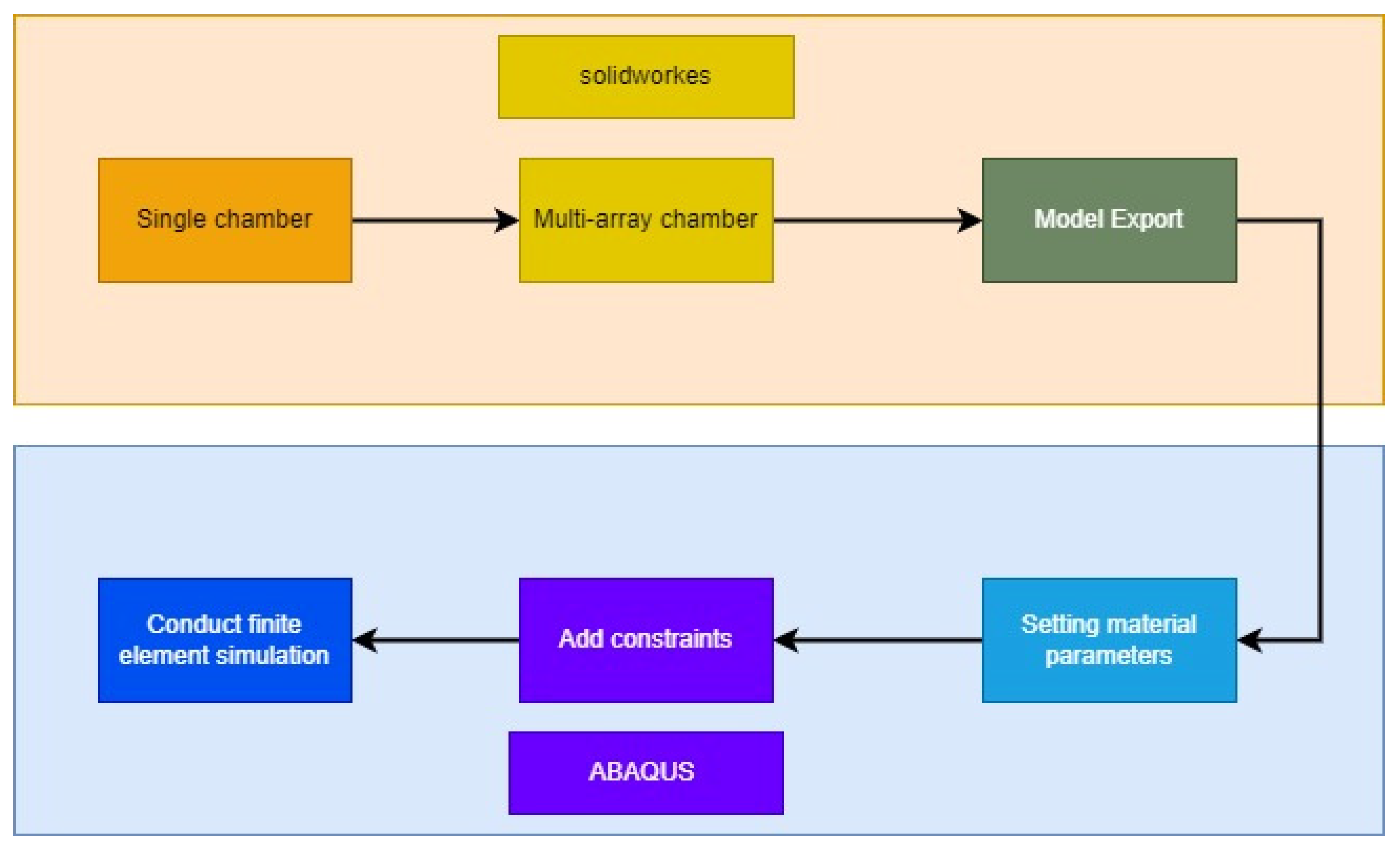
In this research, we strictly controlled the length, width, and other parameters to remain unchanged. For each factor, we selected three sets of parameters for SolidWorks modeling. The specific parameters are shown in Table 2. Then, we performed ABAQUS simulation analysis and used post-processing queries to obtain the bending angle within the range of the selected factor parameters. At the same time, we also studied the changes in the bending angle and pressure on different surfaces under different air pressures and plotted the bending attitude curve of the actuator under different air pressures. Finally, we obtained the movement of the actuator at a pressure of 50 kPa. Figure 6 shows the modeling and simulation process. In the simulation software, we first imported the model, which is created by SolidWorks, then inputted the property parameters of the collected materials, and finally, in order to better simulate the actual physical model, some constraints needed to be established. In a large number of subsequent experiments, the parameters of the model in SolidWorks were generally changed first, and then, the physical constraints were changed in ABAQUS for simulation.
In the modeling process, not only do the shape and size of the soft robot need to be considered, the sensors, drivers, and controllers also need to be adapted to the shape of the soft robot after the shape of the soft robot is determined. Factors that need to be considered include the size of the sensor, the installation location, the power consumption of the driver, the operating speed, and the compatibility of the controller. And as the shape of the soft robot changes, all components need to be readjusted and assembled. It is recommended that when a soft robot of the same shape is enlarged in proportion, the spacing distance in Figure 5 should be appropriately increased, so as to reduce the weight of the soft robot and increase the bending angle.
In order to ensure the accuracy and reliability of the experiment, we strictly controlled the consistency of the length, width, and other parameters during the experiment. By changing the parameter combination of each factor, we can evaluate its impact on the performance of the actuator and draw the corresponding bending angle and attitude curve. Such experimental design and simulation analysis can help us gain an in-depth understanding of the influence of different factors and parameters on the performance of software pneumatic actuators, so as to provide an important reference basis for optimizing their design and control.
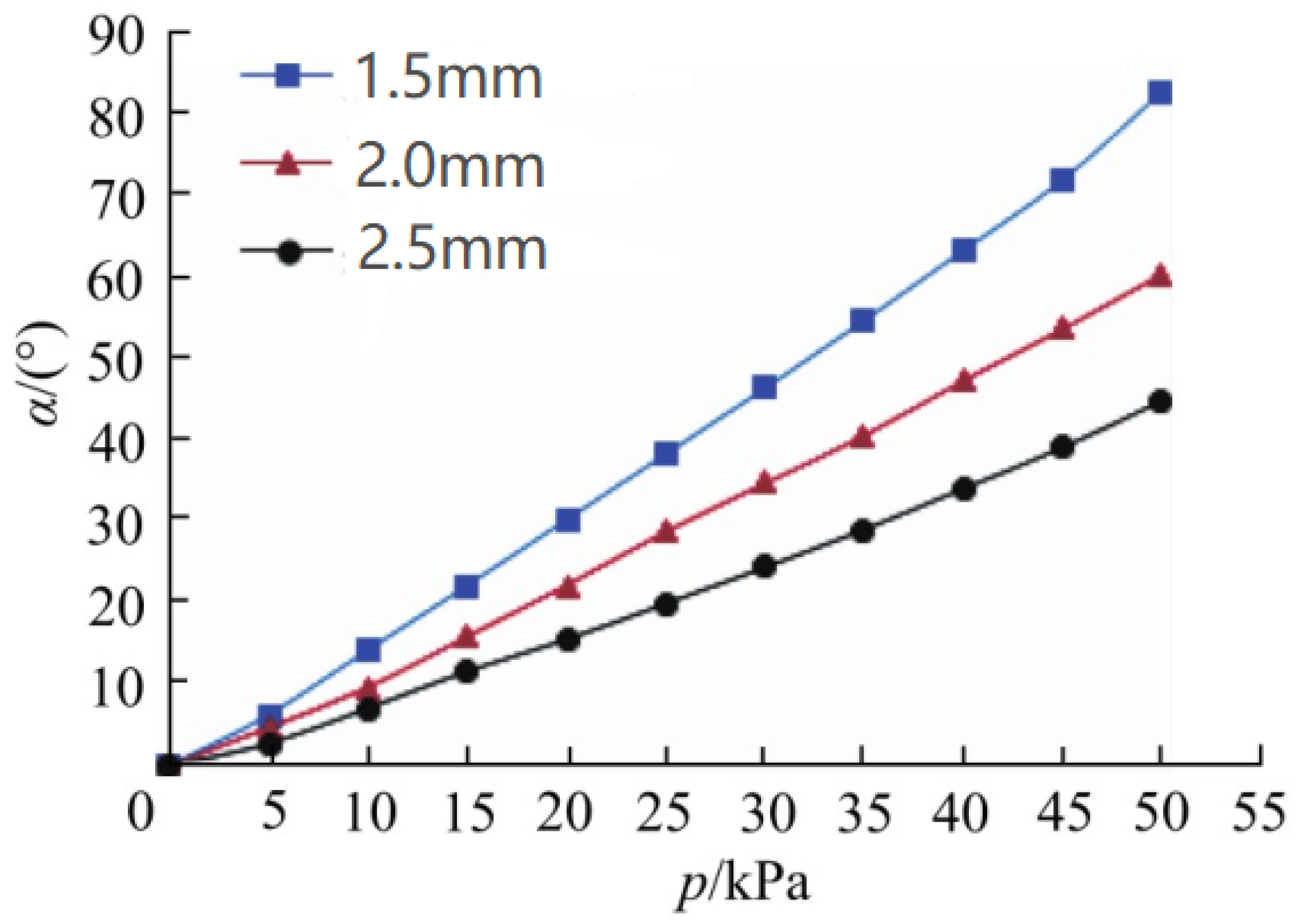
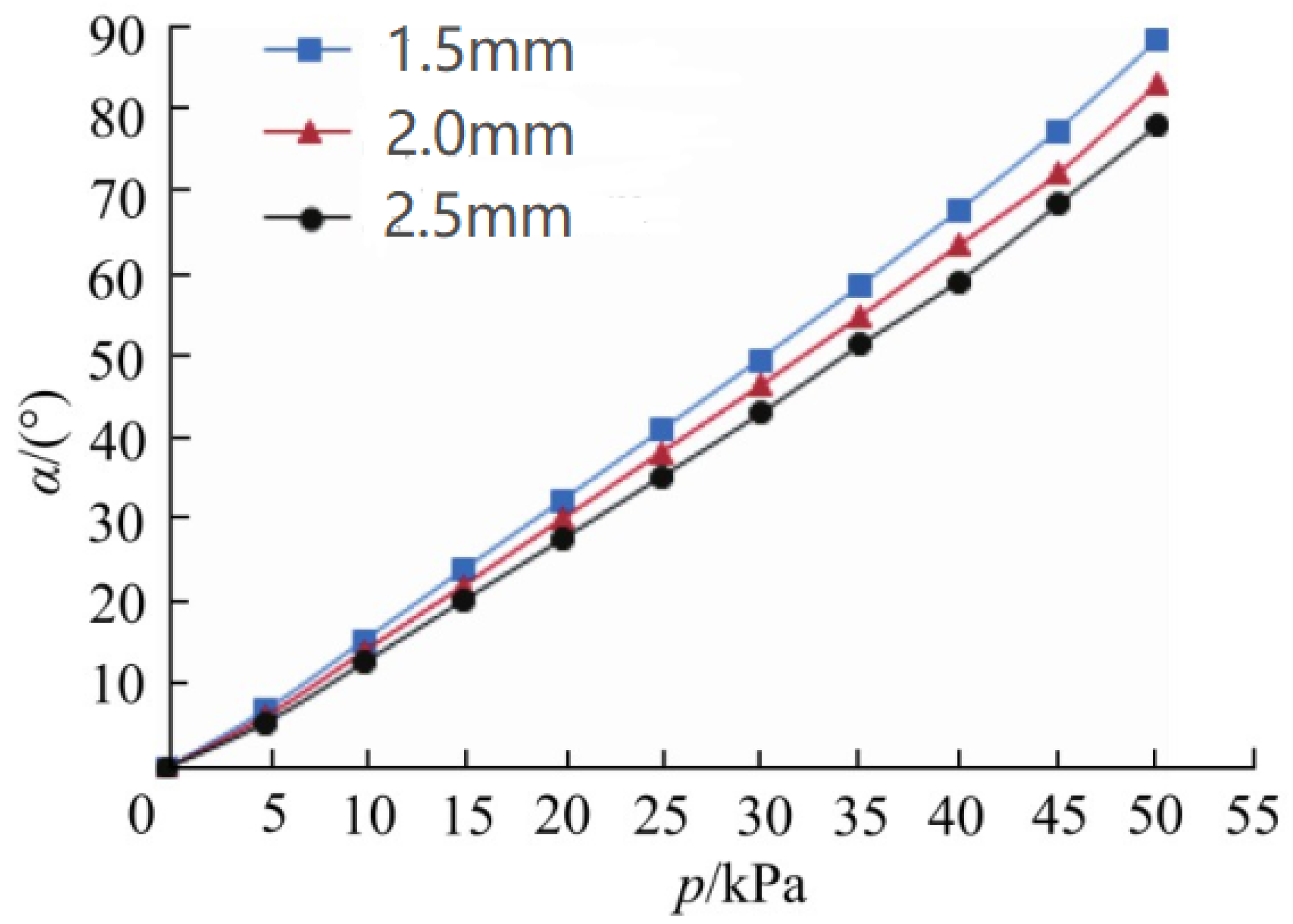
As shown in Figure 7, Figure 8 and Figure 9, we have drawn a diagram of the wall thickness of the air chamber, the spacing of the air chamber, and the relationship between the height of the air chamber and the bending angle of the actuator.
In Figure 6, we observe an inverse relationship between the wall thickness of the air cavity and the bending angle. With the increase in the wall thickness of the air cavity, the bending angle of the actuator decreases. By analyzing this diagram, we can evaluate the degree to which the wall thickness of the air cavity affects the bending angle of the actuator.
Figure 8 shows the relationship between the spacing of the air chamber and the bending angle of the actuator. By analyzing this diagram, we can understand that the spacing of the air cavities is negatively correlated with the change in the bending angle of the actuator.
Finally, in Figure 9, we show the relationship between the height of the air chamber and the bending angle of the actuator. From this diagram, we can observe that the increase in the height of the air cavity will cause the bending angle of the actuator to increase.
Through the finite element analysis of the soft actuators under the action of different factors within the range of the selected factors and parameters, it can be seen that the actuator achieves the best bending effect under the comprehensive action of various factors and parameters. In summary, the combination of factors and parameters in this range is selected as follows: the wall thickness of the air cavity is 1.5 mm, the height of the air cavity is 14 mm, and the spacing between the air cavities is 1.5 mm. This achieves the best combination of fierce element parameters.
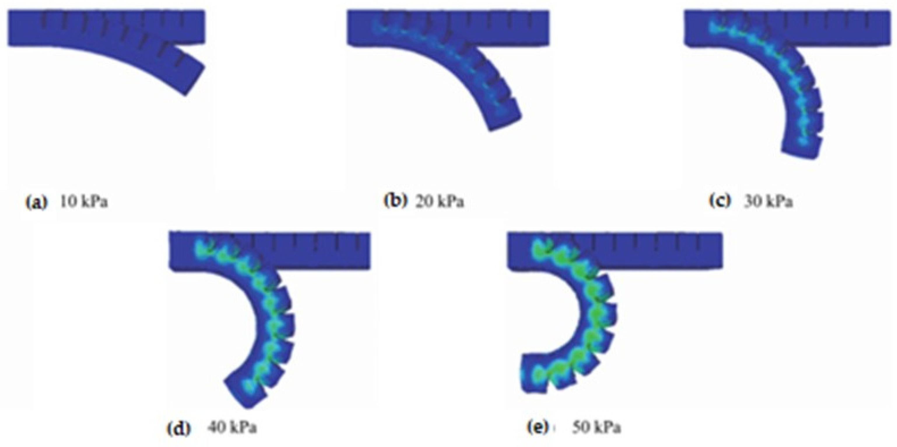
The soft actuator under this parameter is simulated and analyzed at a pressure of 0~50 kPa. Figure 10 shows the bending deformation diagram of the actuator under the best combination. As the air pressure increases, the deformation of the software actuator continues to increase, and the stress is mainly concentrated at the contact of the adjacent air cavity. Drive at 10 Pa pressure
The soft actuator at a pressure of 10 kPa is shown in the Figure 10a, at a pressure of 20 kPa is shown in the Figure 10b, at a pressure of 30 kPa is shown in the Figure 10c, at a pressure of 30 kPa is shown in the Figure 10c, at a pressure of 40 kPa is shown in the Figure 10d, at a pressure of 50 kPa is shown in the Figure 10e.

3. Results and Tests

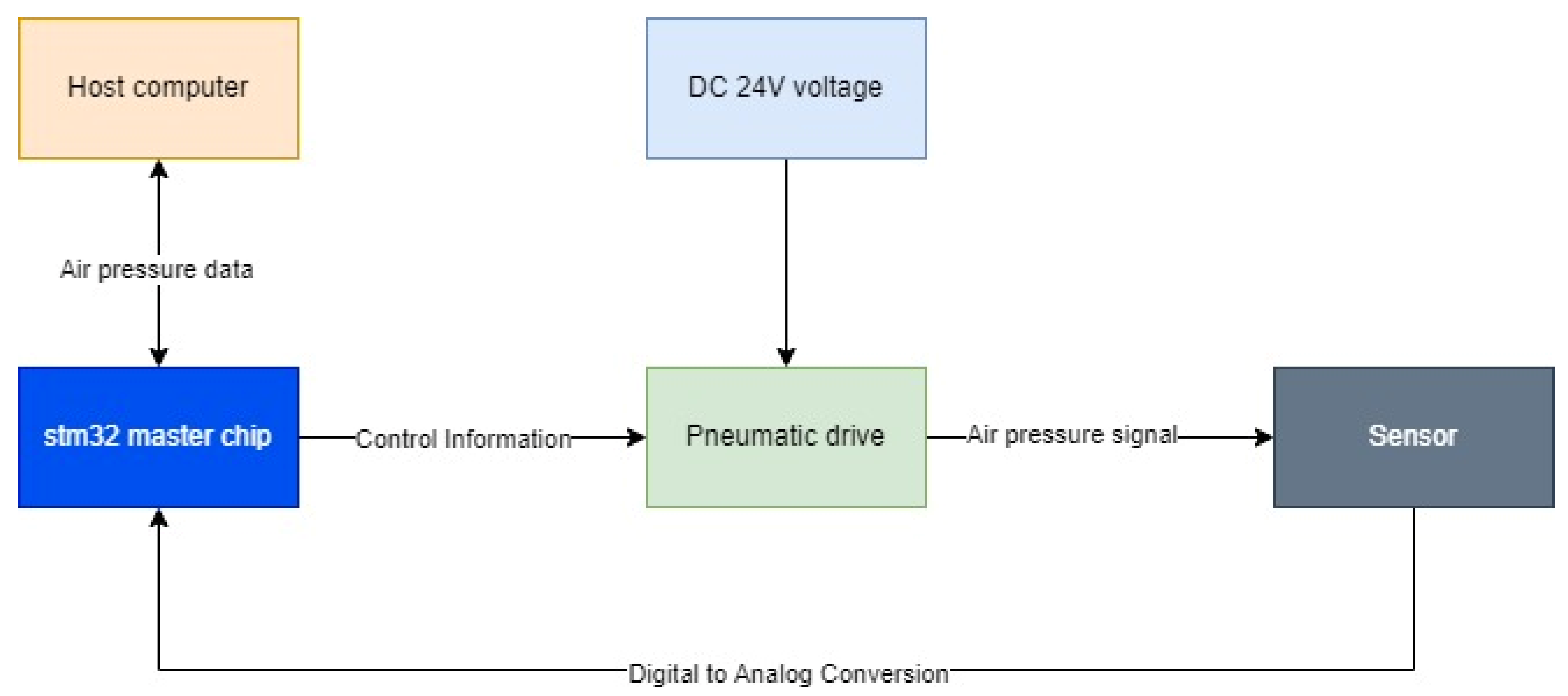
In order to verify the bending performance of the software actuator under different air pressures, an experimental test platform is set up. As shown in Figure 10, the input air pressure is provided by the air pressure pump, which can provide a pressure of 0~4 MPa, and the maximum air flow is 16 L/min. The air pressure passes through the filter-pressure-reducing valve to stabilize and filter impurities. The control program is written by the host computer, and the program is burned to the STM32 single-chip computer to control the electrical proportional valve for digital-to-analog conversion, so that the air pressure at the output of the proportional valve changes with the change in voltage, so that the actuator can achieve the bending effect. The air pressure sensor is connected through the tracheal adapter, which is used to monitor the air pressure entering the soft actuator in real time. Among them, the electrical proportional valve and air pressure sensor are powered by a 24 V DC power supply, the STM32 single-chip microcomputer is powered separately by the USB interface of the host computer, and the ship-type switch is used to control the on–off of the circuit. In soft robots, there are barometers, force tactile sensors, and encoders. With the integration of multiple sensors, the shape, weight, and power consumption of the robot will change, and soft robots often have more stringent requirements on their own shape, size, endurance, and cost. Therefore, such components will be reduced in soft robots in order to use each sensor as efficiently as possible. In order to achieve a small shape, light weight, and low power consumption, 3D printing can be used to reduce the weight and volume of materials or sensors, or machine learning algorithms can be used to extract features, train, and model massive sensor information, trying to replace redundant sensors. Figure 11 shows the architecture of the soft robot in the experiment, including components such as the controller, drive, and power supply.
As shown in Figure 12, the output air pressure of the proportional valve is controlled by the single-chip microcomputer, so that the actuator reaches different degrees of bending, and the angle between the straight line connected from the apex of the soft actuator to the origin and the x axis is recorded on the grid paper. The angle is the measurement angle, as shown in Figure 13.
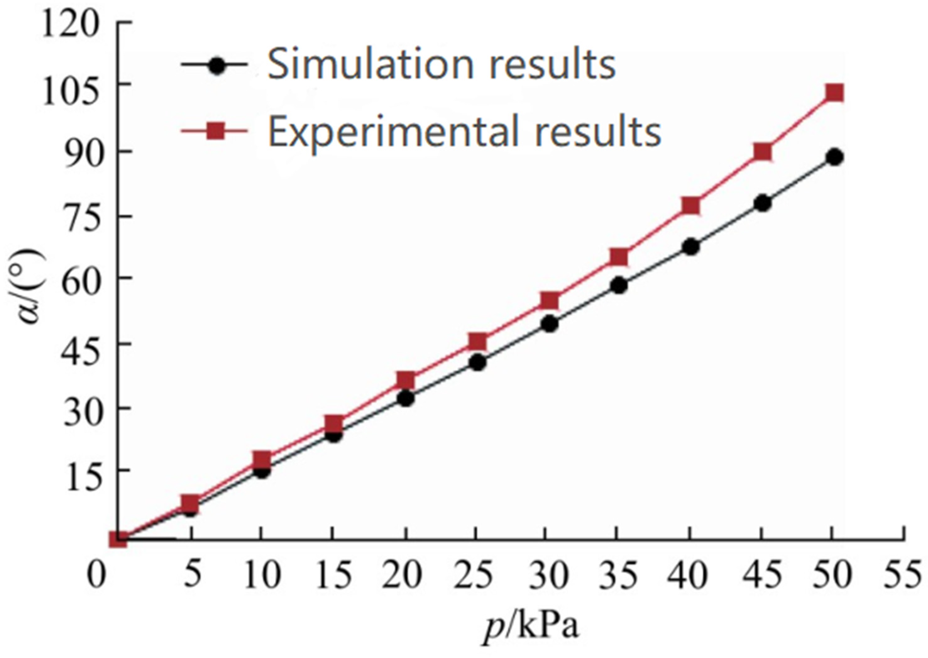
As shown in Figure 14, analyzing the experimental data, it can be seen that the experimental measurement of the bending angle is close to the trend of finite element simulation. At 40 kPa air pressure, the experimental measurement of the bending angle is 77.1° and the finite element simulation angle is 67.4°. Dragon Skin 30 silicone has excellent physical strength and can withstand greater pressure and deformation. For hollow soft robots, gravity has little effect on their horizontal and vertical placement.
A possible reason for the error in the experimental measurement and simulation results is due to the human production error of the software pneumatic actuator during the physical production process.
As can be seen from Figure 14, the angle changes in the simulation and the real object were tested twelve times under different air pressures. In both environments, from low pressure to high pressure, the error between the two gradually increases, this increase is stable and tolerable, and the error can be compensated by the algorithm. Possible sources of error include materials, sensors, and simulation parameters.
Through the final test results, we found that the simulation results are basically the same as the physical test results, indicating that the designed pneumatic software actuator has reached the level of the simulation model in terms of physical performance. This shows that our simulation analysis has high accuracy and reliability. By comparing the consistency of the simulation results and the physical test results, we can confirm that the design and optimization of the proposed pneumatic software actuator is successful. This further verifies the effectiveness of our research methods and analysis work and provides an important reference and guidance for further research and application in the field of pneumatic software actuators in the future.

4. Discussion

In this article, first of all, we designed the physical structure of an actuator to ensure that it has good mechanical properties and reliability. Then, through the uniaxial tensile experiment, we measured and determined the parameter properties of the silicon material, which provided accurate material parameters for subsequent simulation analysis. Then, we selected three groups of factors that have an important impact on the bending performance of the actuator and used Abaqus 6.14 software for simulation analysis. Through the simulation analysis, we obtained the law of change in air pressure and bending angle under different combinations of factors and parameters, as well as the bending attitude curve and range of motion of the actuator under different conditions. These results provide an important reference for further optimizing and improving the design of the actuator.
By comparing and analyzing the simulation results under different factors and parameter combinations, we determined the best combination of factors and parameters. We determined that the optimal wall thickness of the air cavity is 1.5 mm, the height of the air cavity is 14 mm, and the spacing between the air cavities is 1.5 mm. Based on these parameters, we made a physical model and established an experimental platform to perform experimental measurements on the actuator by entering a pressure of 0~50 kPa. The experimental measurement results show that under different air pressures, the bending angle of the actuator is basically the same as the trend of the simulation model. However, due to certain errors in the production process of physical objects, the bending angle that was measured experimentally slightly exceeds the finite element simulation results under the same air pressure. In addition, the range of motion measured in the experiment is slightly wider, which further verifies the reliability of the simulation analysis results. In summary, through the research in this paper, we have successfully proposed a new type of pneumatic software actuator and carried out structural design, parameter performance determination, and simulation analysis on it. These research results provide an important theoretical and experimental basis for the further optimization and application of pneumatic software actuators.

Author Contributions

Conceptualization, E.M.; Methodology, Y.K.; Software, Y.K. and E.M.; Validation, Y.Y.; Formal analysis, S.U.; Investigation, Y.K.; Resources, S.U.; Data curation, E.M. and Y.Y.; Writing—original draft, Y.K. and Y.Y. All authors have read and agreed to the published version of the manuscript.

Funding

This research received no external funding.

Data Availability Statement

The original contributions presented in the study are included in the article, further inquiries can be directed to the corresponding author/s.

Conflicts of Interest

The authors declare no conflicts of interest.

References

  1. Rothemund, P.; Kim, Y.; Heisser, R.H.; Zhao, X.; Shepherd, R.F.; Keplinger, C. Shaping the future of robotics through materials innovation. Nat. Mater. 2021, 20, 1582–1587. [Google Scholar] [CrossRef] [PubMed]
  2. Rich, S.I.; Wood, R.J.; Majidi, C. Untethered soft robotics. Nat. Electron. 2018, 1, 102–112. [Google Scholar] [CrossRef]
  3. Wehner, M.; Truby, R.L.; Fitzgerald, D.J.; Mosadegh, B.; Whitesides, G.M.; Lewis, J.A.; Wood, R.J. An integrated design and fabrication strategy for entirely soft autonomous robots. Nature 2016, 536, 451–455. [Google Scholar] [CrossRef] [PubMed]
  4. Xu, Q.; Ying, C.; Zhang, K.; Xie, H.; E, S. An effective nonlinear dynamic formulation to analyze grasping capability of soft pneumatic robotic gripper. Int. J. Smart Nano Mater. 2024, 1–27, ahead-of-print. [Google Scholar] [CrossRef]
  5. Majidi, C. Soft-matter engineering for soft robotics. Adv. Mater. Technol. 2019, 4, 1800477. [Google Scholar] [CrossRef]
  6. Branyan, C.; Fleming, C.; Remaley, J.; Kothari, A.; Tumer, K.; Hatton, R.L.; Mengüç, Y. Soft snake robots: Mechanical design and geometric gait implementation. In Proceedings of the 2017 IEEE International Conference on Robotics and Biomimetics (ROBIO), Macau, China, 5–8 December 2017; pp. 282–289. [Google Scholar]
  7. Cortes-Gonzalez, J.G.; Sandoval-castro, X.Y.; Torres, M.F.R.; Castillo-Castaneda, E. Bio-inspired Design of a Soft Bending Actuator for Flexion of a Human Index Finger: A Case Study. Adv. Mech. Mach. Sci. 2023, 148, 620. [Google Scholar]
  8. Sokolov, O.; Hošovský, A.; Trojanová, M. Design, Modelling, and Control of Continuum Arms with Pneumatic Artificial Muscles: A Review. Machines 2023, 11, 936. [Google Scholar] [CrossRef]
  9. Niu, H.; Feng, R.; Xie, Y.; Jiang, B.; Sheng, Y.; Yu, Y.; Baoyin, H.; Zeng, X. MagWorm: A Biomimetic Magnet Embedded Worm-Like Soft Robot. Soft Robot. 2021, 8, 507–518. [Google Scholar] [CrossRef] [PubMed]
  10. Qi, X.; Shi, H.; Pinto, T.; Tan, X. A novel pneumatic soft snake robot using traveling-wave locomotion in constrained environments. IEEE Robot. Autom. Lett. 2020, 5, 1610–1617. [Google Scholar] [CrossRef]
  11. Zakharov, L.A.; Martyushev, D.A.; Ponomareva, I.N. Predicting dynamic formation pressure using artificial intelligence methods. J. Min. Inst. 2022, 253, 23–32. [Google Scholar] [CrossRef]
  12. Leonidovich, Z.Y.; Kovalchuk, M.S.; Batueva, D.E.; Senchilo, N.D. Development of an algorithm for regulating the load schedule of educational institutions based on the forecast of electric consumption within the framework of application of the demand response. Sustainability 2021, 13, 13801. [Google Scholar] [CrossRef]
  13. Calderón, A.A.; Ugalde, J.C.; Zagal, J.C.; Pérez-Arancibia, N.O. Design fabrication and control of a multi-material-multi-actuator soft robot inspired by burrowing worms. In Proceedings of the 2016 IEEE International Conference on Robotics and Biomimetics (ROBIO), Qingdao, China, 3–7 December 2016; pp. 31–38. [Google Scholar]
  14. Xavier, M.S.; Fleming, A.J.; Yong, Y.K. Image-guided locomotion of a pneumatic-driven peristaltic soft robot. In Proceedings of the 2019 IEEE International Conference on Robotics and Biomimetics (ROBIO), Dali, China, 6–8 December 2019; pp. 2269–2274. [Google Scholar]
  15. Hou, T.; Yang, X.; Su, H.; Chen, L.; Wang, T.; Liang, J.; Zhang, S. Design fabrication and morphing mechanism of soft fins and arms of a squid-like aquatic-aerial vehicle with morphology tradeoff. In Proceedings of the 2019 IEEE International Conference on Robotics and Biomimetics (ROBIO), Dali, China, 6–8 December 2019; pp. 1020–1026. [Google Scholar]
  16. Zemenkova, M.Y.; Chizhevskaya, E.L.; Zemenkov, Y.D. Intelligent monitoring of the condition of hydrocarbon pipeline transport facilities using neural network technologies. J. Min. Inst. 2022, 258, 933–944. [Google Scholar] [CrossRef]
  17. Shamil, I.R.; Grigoriev ABeloglazov, I.I.; Savchenkov, S.A.; Gudmestad, O.T. Research risk factors in monitoring well drilling—A case study using machine learning methods. Symmerty 2021, 13, 1293. [Google Scholar]
  18. Chen, A.; Yin, R.; Cao, L.; Yuan, C.; Ding, H.; Zhang, W. Soft robotics: Definition and research issues. In Proceedings of the 24th International Conference on Mechatronics and Machine Vision in Practice (M2VIP), Auckland, New Zealand, 21–23 November 2017; pp. 366–370. [Google Scholar]
  19. Filippov, E.V.; Zakharov, L.A.; Martyushev, D.A.; Ponomareva, I.N. Reproduction of reservoir pressure by machine learning methods and study of its influence on the cracks formation process in hydraulic fracturing. J. Min. Inst. 2022, 258, 924–932. [Google Scholar] [CrossRef]
  20. Yang, J.; Wang, F.; Lu, Y. Design of a Bistable Artificial Venus Flytrap Actuated by Low Pressure with Larger Capture Range and Faster Responsiveness. Biomimetics 2023, 8, 181. [Google Scholar] [CrossRef] [PubMed]
  21. Mészáros, A.; Sárosi, J. Increasing the Force Exertion of a Soft Actuator Using Externally Attachable Inter-Chamber Plates. Actuators 2023, 12, 222. [Google Scholar] [CrossRef]
  22. van Vlerken, C.; Ballen-Moreno, F.; Roels, E.; Ferrentino, P.; Langlois, K.; Vanderborght, B.; Verstraten, T. Development of an Active Physical Interface for Physical Human-Robot Interaction: Investigation of Soft Pneumatic Actuator Straps for Automatic Enclosure System. Actuators 2023, 12, 241. [Google Scholar] [CrossRef]
  23. Zhukovskiy, Y.L.; Koshenkova, A.A.; Vorobieva, V.A.; Raspunin, D.L. Assessment of the Impact of Technological Development and Scenario Forecasting of the Sustainable Development of the Fuel and Energy Complex. Energies 2023, 16, 3185. [Google Scholar] [CrossRef]
  24. Hu, W.; Alici, G. Bioinspired three-dimensional-printed helical soft pneumatic actuators and their characterization. Soft Robot 2020, 7, 267–282. [Google Scholar] [CrossRef]
  25. Beloglazov, I.I.; Plaschinsky, V.A. Development MPC for the Grinding Process in SAG Mills Using DEM Investigations on Liner Wear. Materials 2024, 17, 795. [Google Scholar] [CrossRef]
  26. Romashev, A.O.; Nikolaeva, N.V.; Gatiatullin, B.L. Adaptive approach formation using machine vision technology to determine the parameters of enrichment products deposition. J. Min. Inst. 2022, 256, 677–685. [Google Scholar] [CrossRef]
  27. Gorissen, B.; Reynaerts, D.; Konishi, S.; Yoshida, K.; Kim, J.-W.; De Volder, M. Elastic inflatable actuators for soft robotic applications. Adv. Mater. 2017, 29, 1604977. [Google Scholar] [CrossRef] [PubMed]
  28. Polygerinos, P.; Correll, N.; Morin, S.A.; Mosadegh, B.; Onal, C.D.; Petersen, K.; Cianchetti, M.; Tolley, M.T.; Shepherd, R.F. Soft robotics: Review of fluid-driven intrinsically soft devices; manufacturing sensing control and applications in human-robot interaction. Adv. Eng. Mater. 2017, 19, 1700016. [Google Scholar] [CrossRef]
  29. Kozhubaev, Y.N.; Ovchinnikova, E.N.; Ivanov, V.Y.; Krotova, S.Y. Incremental Machine Learning for Soft Pneumatic Actuators with Symmetrical Chambers. Symmetry 2023, 15, 1206. [Google Scholar] [CrossRef]
  30. Mayer, A.; Müller, D.; Raisch, A.; Hildebrandt, A.; Sawodny, O. Demonstration-based Programming of Multi-Point Trajectories for Collaborative Continuum Robots. IFAC-PaperOnLine 2019, 52, 513–518. [Google Scholar] [CrossRef]
  31. Zhang, Z.; Long, Y.; Chen, G.; Wu, Q.; Wang, H.; Jiang, H. Soft and lightweight fabric enables powerful and high-range pneumatic actuation. Sci. Adv. 2023, 9, eadg1203. [Google Scholar] [CrossRef] [PubMed]
  32. Drotman, D.; Jadhav, S.; Sharp, D.; Chan, C.; Tolley, M.T. Electronics-free pneumatic circuits for controlling soft-legged robots. Sci. Robot. 2021, 6, eaay2627. [Google Scholar] [CrossRef] [PubMed]
  33. Chen, F.; Song, Z.; Chen, S.; Gu, G.; Zhu, X. Morphological Design for Pneumatic Soft Actuators and Robots with Desired Deformation Behavior. Trans. Robot. 2023, 39, 4408–4428. [Google Scholar] [CrossRef]
  34. Zhang, T.; Wang, K.; Tang, W.; Qin, K.; Liu, Y.S.Y.; Zou, J. Design and analysis of flexible bending actuator driven by electrohydrodynamic pumps. J. Eng. Des. 2023, 30, 467–475. [Google Scholar] [CrossRef]
  35. Makhovikov, A.; Kryltsov, S.B.; Matrokhina, K.V.; Trofimets, V.Y. Secure corporate communication system for a metallurgical enterprise Non-ferrous metal. Non-Ferr. Met. 2023, 4, 5–13. [Google Scholar] [CrossRef]
  36. Matrokhina, K.V.; Trofimets, V.Y.; Mazakov, E.B.; Makhovikov, A.B.; Khaykin, M.M. Development of methodology for scenario analysis of investment projects of enterprises of the mineral resource complex. J. Min. Inst. 2023, 259, 112–124. [Google Scholar] [CrossRef]
Figure 1. Structural diagram.
Symmetry 16 00750 g001
Figure 2. Schematic diagram of model bending.
Symmetry 16 00750 g002
Figure 3. Sample size diagram.
Symmetry 16 00750 g003
Figure 4. Stress–strain diagram.
Symmetry 16 00750 g004
Figure 5. Annotation diagram of each factor.
Symmetry 16 00750 g005
Figure 6. Experimental modeling and simulation flow chart.
Symmetry 16 00750 g006
Figure 7. Diagram of the thickness and bending angle of the air wall.
Symmetry 16 00750 g007
Figure 8. Diagram of the spacing and bending angle of the air wall.
Symmetry 16 00750 g008
Figure 9. Diagram of the height and bending angle of the air wall.
Symmetry 16 00750 g009
Figure 10. Bending deformation under optimal parameter combination.
Symmetry 16 00750 g010
Figure 11. Experimental test platform.
Symmetry 16 00750 g011
Figure 12. Experimental flow chart.
Symmetry 16 00750 g012
Figure 13. Actuator bending diagram.
Symmetry 16 00750 g013
Figure 14. Diagram of air pressure and bending angle.
Symmetry 16 00750 g014
Table 1. Software actuator parameters.
ParameterValues (mm)
length125
width20
height22
Table 2. Parameters of different factors.
FactorParameter (mm)
123
Air cavity wall thickness1.52.02.5
Air cavity inquiry distance1.52.02.5
Air cavity height1011.012.0
Disclaimer/Publisher’s Note: The statements, opinions and data contained in all publications are solely those of the individual author(s) and contributor(s) and not of MDPI and/or the editor(s). MDPI and/or the editor(s) disclaim responsibility for any injury to people or property resulting from any ideas, methods, instructions or products referred to in the content.