Abstract
In the present paper, the dynamic behaviors of a bubble collapsing at the symmetrical positions of the double cylinders within a narrow gap are qualitatively and quantitatively investigated. Using a high-speed photographic technique, the morphological evolution of a bubble near the double cylinders in a two-dimensional flow field is explored and qualitatively demonstrated. The mechanism by which the position of the bubble affects its dynamics is revealed. At the symmetrical position of the double cylinders, the bubble’s dimensionless abscissa shows significant impacts on the collapse behaviors, and its increase weakens the bubble deformation and strengthens the centroid movement.
1. Introduction
Cavitation has been widely researched and applied in ultrasonic cleaning technology [1,2,3]. It has significant impacts on the fluid machinery and removes the dirt on the surface [4,5,6]. Inside various fluid machinery components (e.g., valves [7], nozzles [8], and bearings [9]), curved boundaries widely exist. At this point, under the influence of various curved walls (e.g., cylinders as a common case), bubble collapse deformations, jets, and other types of dynamic behaviors are difficult to predict [10,11,12].
Regarding the cavitation bubble dynamics near various walls, the research can be divided into that on angular walls [13,14,15,16,17], curved walls [18,19,20,21,22,23,24,25,26,27,28], and particles [29,30,31,32,33,34,35]. In terms of angular walls, research has involved various angles. Blake and Cerone [13] proposed a Kelvin impulse theory that can be employed to characterize bubble centroid movements and jet characteristics near angular walls. Based on this theory, Wang et al. [14] theoretically investigated restricted bubble collapse behaviors near a 90° angle wall, which were verified though high-speed photographic experiments. They found that the Kelvin impulse acting on the bubble was largest at the vertex of the 90° angle wall and decreased with increasing distance. Near a 180° angle wall, Zhang et al. [15] observed a heart-shaped collapse of the bubble and the jets toward and away from the wall through experiments. In addition, Wang et al. [16] conducted a numerical investigation on a bubble near angular walls and found that for a wall with a smaller angle, the bubble had a longer oscillation period, a wider jet width, and a smaller jet velocity.
The investigations of a bubble collapsing near curved walls have involved basic curved walls [18,19,20,21,22,23] and hydrofoils [24,25,26,27,28]. Takahira et al. [18] derived the motion equation of a spherical bubble near a curved rigid wall and concluded that the curvature is positively correlated with the liquid pressure. Based on electric spark experiments, Ma et al. [19] found a negative correlation between the curvature and the bubble shock wave loads. Moloudi et al. [20] conducted numerical research on bubble collapse characteristics near a convex wall and obtained the bubble–wall distance range that leads to non-spherical deformations during the growth and collapse processes. Požar et al. [21] investigated the evolution characteristics of bubble shock waves near concave walls through high-speed photography and Schlieren techniques. They found that, unlike with flat and convex walls, the shock wave generated when a bubble collapses near a concave wall is re-aggregated by the wall and causes secondary cavitation at the focal point. Ma et al. [22] positioned a convex wall at a 45-degree angle to the upper left of the bubble and identified six typical bubble collapse morphologies through high-speed photography experiments. Furthermore, Li et al. [23] conducted experimental research on an elastic convex wall, observing the phenomenon of the counter jet away from the wall and exploring its formation mechanism. Shen et al. [24] theoretically investigated restricted bubble dynamics near symmetric and asymmetric hydrofoils and verified them through high-speed photography experiments. Also, based on the experiments, they divided the bubble collapse deformations (namely, penetrating deformation, triangular depression, and arc-shaped depression collapses) into three types according to bubble–hydrofoil distance. Based on the large eddy simulation approach, Pendar et al. [25] researched the phenomena of condensation, detachment, flow, and shedding of bubble clouds near the leading edge of hydrofoils.
For research into particles, Wang et al. [29] established a Kelvin impulse theoretical model for a bubble collapsing near a spherical particle and verified the accuracy of the model through experiments. Based on this theory, Zhang et al. [30] explored a bubble’s morphological evolutionary characteristics near triple symmetrically arranged particles. They found a positive correlation between the bubble’s maximum radius and the non-circularity of the bubble, while the particle–bubble distance had an opposite effect. In addition, Wu et al. [31] experimentally investigated the dynamic behaviors of a free-settling particle driven by a bubble near a rigid wall. They found that when the particle was very close to the bubble, the growth of the bubble had a strong acceleration effect on the particle and caused it to collide with the flat walls. However, due to the influence of the liquid flow and pressure on the rigid wall, the velocity of the particle decreased when it approached the wall surface.
Research within confined spaces is still in its early stages. For example, Wang et al. [36] investigated the characteristics of bubble collapse at the edge of a gap. And Quinto Su et al. [37] investigated the influence of gap thickness. Nevertheless, the influence of the cylindrical boundaries on the bubble dynamics within a narrow gap is not yet clear. Specifically, there are multiple types of cylindrical components inside hydraulic machinery, often accompanied by narrow fluid channels in their proximity. For example, cylindrical pins and bearings require assembly with other components, creating narrow fluid channels between them [38]. In addition, the fluid channel around the cylindrical rotor inside a vane pump is also narrow and prone to cavitation [39]. Investigating bubble dynamics in confined spaces near cylinders will illuminate the mechanisms of their impact, bearing profound implications for the safe operation of fluid machinery.
Therefore, the present paper experimentally investigates the bubble dynamics near double cylinders within a narrow gap and demonstrates the typical collapse deformations qualitatively. Also, the bubble interface velocities, centroid movements, and durations of the oscillation period are analyzed quantitatively. The present paper is organized as follows: Section 2 exhibits the high-speed photography platform and the typical photographs of a bubble collapsing near double cylinders. Section 3 presents the typical experimental phenomena of bubble collapse. Section 4 analyzes the bubble deformations and centroid movements. Finally, Section 5 summarizes the results of this research.
2. Experimental Setup
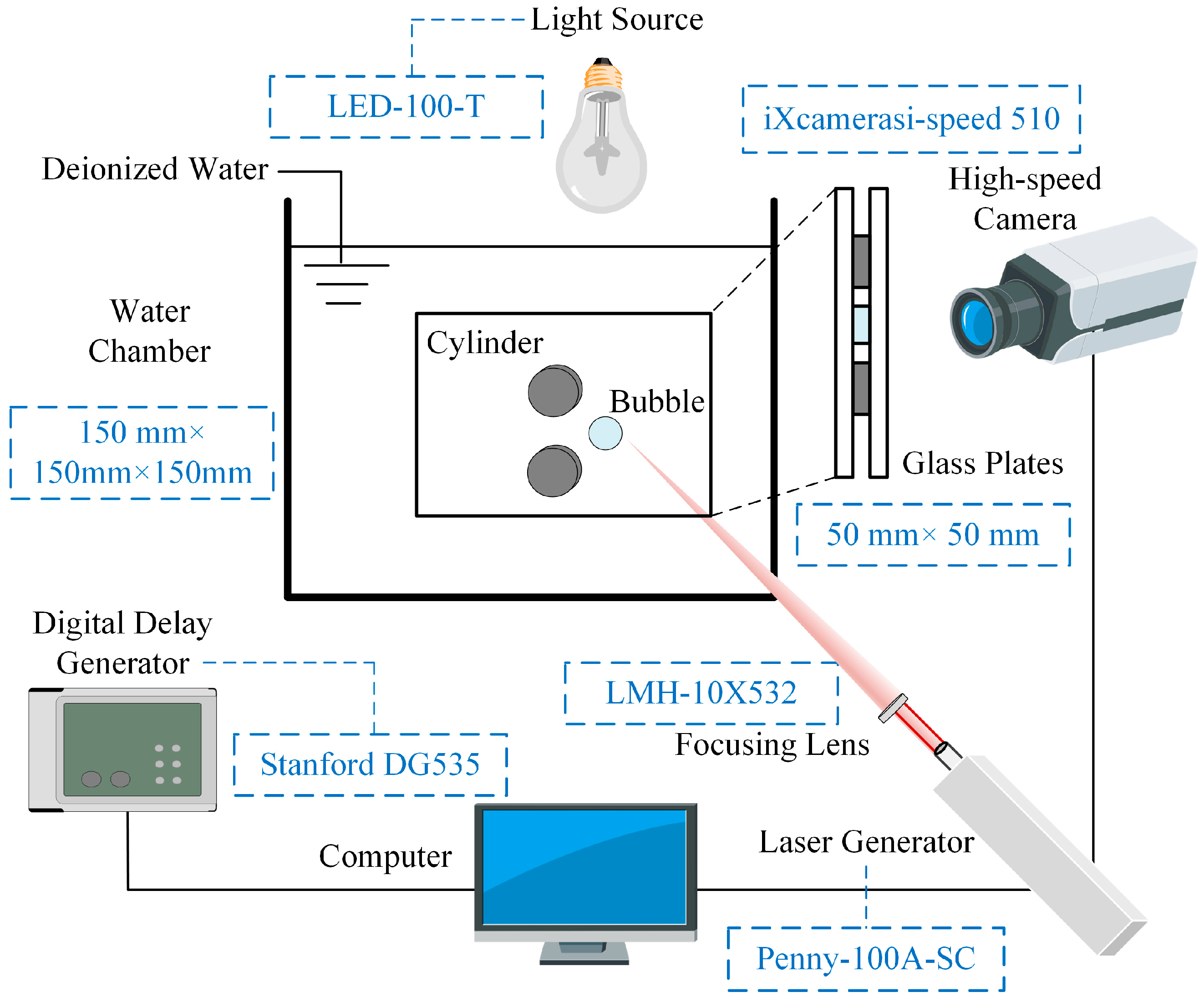
In the present study, the challenge of the experiments was how to consistently form cavitation bubbles within a narrow gap and conduct systematic parameterization investigations on them. Figure 1 shows the configuration of the experimental system. In the figure, the models of the experimental components are presented in the blue dashed boxes. In the experiment, the narrow gap was formed by two parallel plates with a spacing (h) of 1.5 mm, which was smaller than the experimental bubble radius. Thus, the bubble growing within the narrow gap maintained a good cylindrical shape during the first oscillation period. And, the liquid flow field within the narrow gap was used to simulate a two-dimensional incompressible, inviscid, and irrotational flow field. The experimental process and the functions of the components were induced as follows: Firstly, two cylinders with a height of 1.5 mm were placed between two parallel plates and fixed with tools to form a gap with a spacing of 1.5 mm. The gap restricted the axial motion of the bubble, while the radial motion was significant. Also, the cylinders further restricted the movement of the bubble. Both the cylinders and the plates were made of glass. Then, the model was immersed in a water chamber filled with deionized water. As shown in Figure 1, the glass plates and the water chamber were sufficiently large relative to the cylinders (with a radius of 3.5 mm) and the bubble.
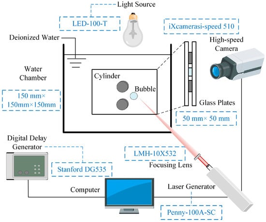
Figure 1.
Configuration of experimental system. The blue dashed boxes show the models of the experimental components.
Subsequently, the camera-captured interface was illuminated by a light source, and the model was adjusted to the appropriate position. The digital delay generator controlled the laser generator and the camera (100,000 fps) to run simultaneously. The laser beam (with a duration of 10 μs and a wavelength of 532 nm) generated a vapor bubble near the double cylinders through a focusing lens, while the camera captured a video of about 2 ms. During the experiment, the position of the bubble could be controlled by a three-dimensional translation platform, and the bubble size could be adjusted by controlling the laser energy, which was fixed at approximately 40 mJ in the present study. The parameter to be adjusted in the current study was the bubble abscissa. Therefore, by shifting the entire narrow gap model to the left, the bubble abscissa relative to the cylinder changed while the position of the bubble remained unchanged. Moreover, the maximum bubble radius ranged from 1.6 to 2.0 mm depending on the bubble abscissa. And, the surface tension was about 0.0725 N/m at ordinary temperature.
Figure 2 shows the definitions of the main parameters for a bubble collapsing near double cylinders. In the figure, two cylinders are arranged vertically, and the bubble is placed at symmetrical positions. The radius of the cylinders (Rw) is 3.5 mm, with a spacing (l) of 1.5 mm. Several dimensionless quantities are defined as follows:
Here, Rw is the radius of the cylinder, Rmax is the maximum radius of the bubble, X0 is the abscissa of the bubble, t is the time, and T is the time from the bubble inception to the first complete collapse. In addition, the left and right endpoints of the bubble are defined as the feature points A and B, respectively.
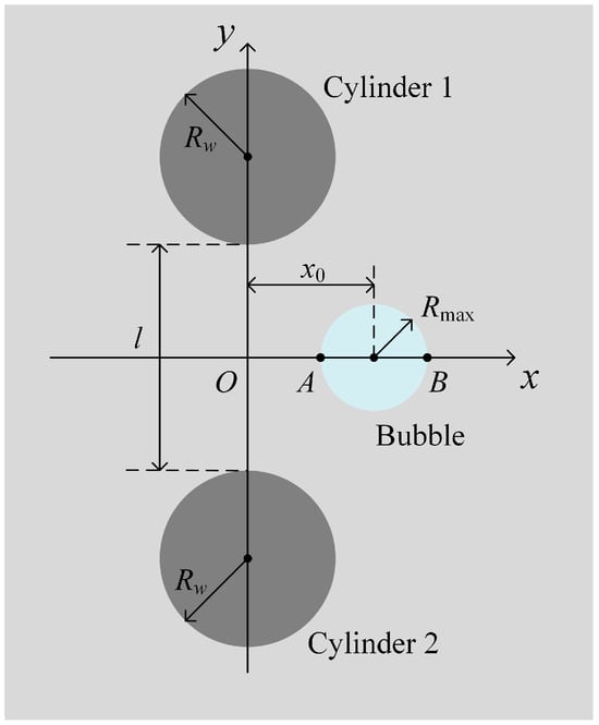
Figure 2.
Definitions of the main parameters for a bubble collapsing near double cylinders.
3. Analysis of the Typical Experimental Phenomena
In this section, the typical experimental phenomena of a bubble collapsing near double cylinders are demonstrated and qualitatively analyzed. The mechanism by which the position of the bubble affects its dynamics is revealed.
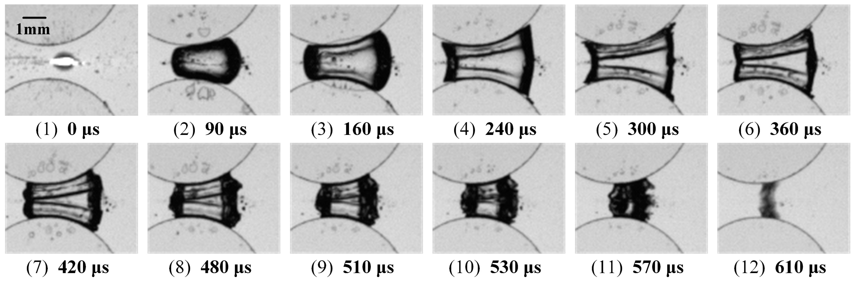
Based on a large number of high-speed photographic experiments, the bubble position was found to have a significant impact on the bubble collapse behaviors near the double cylinders. And, three typical collapse cases are summarized when the bubble is located at the symmetrical positions of the double cylinders. Figure 3, Figure 4 and Figure 5 show typical photographs of a bubble collapsing near the double cylinders for cases 1–3. In the figure, twelve frames of the images during the first bubble oscillation period are displayed, with the time marked at the bottom and the scale marked at the top left of the first frame. Subfigures (1)–(4) correspond to the bubble growth stage when the bubble reaches its maximum volume at the moment of subfigure (4). And, subfigures (5)–(12) correspond to the bubble collapse stage. Due to limitations in the focusing method of the experimental platform, the laser beam was focused onto a strip of light spot. And, under the influence of this light spot, a liquid column remained inside the bubble at the beginning of the bubble formation. Then, as the bubble grew, the liquid column broke up into small droplets, which followed an undisturbed uniform trajectory. Yet, the phenomenon caused by the light spot cannot be fully explained, which may have been due to the reflected shock waves.
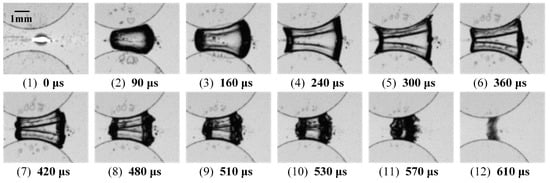
Figure 3.
Typical photographs of a bubble collapsing near double cylinders for case 1. l* = 0.37.
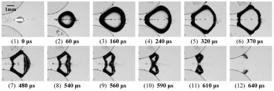
Figure 4.
Typical photographs of a bubble collapsing near double cylinders for case 2. l* = 1.34.
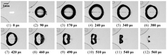
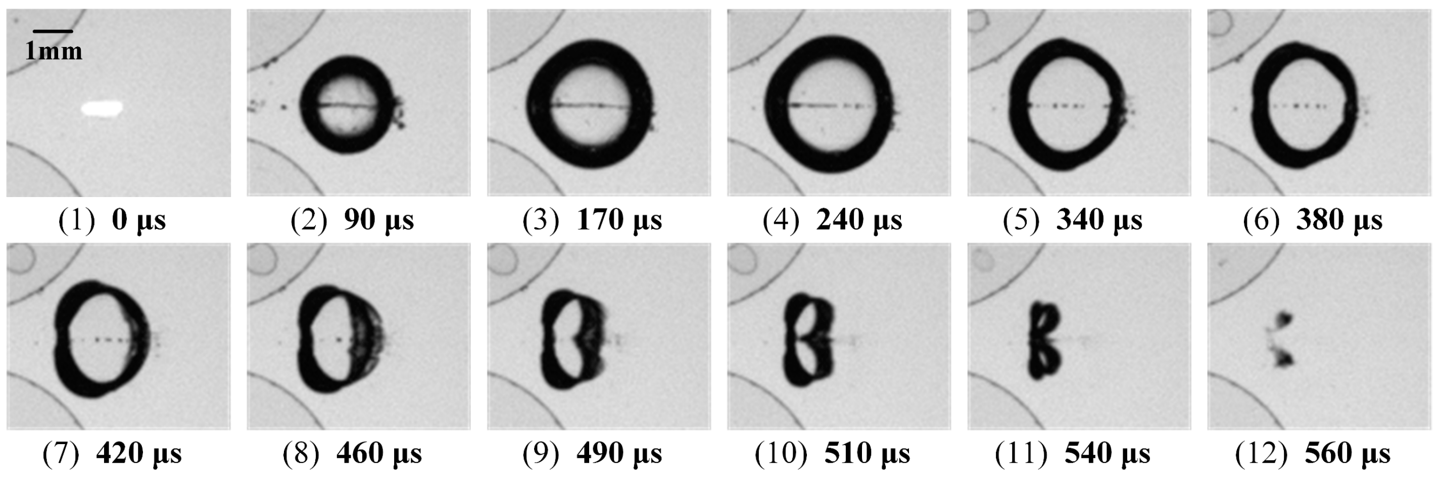
Figure 5.
Typical photographs of a bubble collapsing near double cylinders for case 3. l* = 1.94.
Under different dimensionless abscissas (l*), three typical collapse cases are mainly distinguished by the evolution of the bubble morphology. The primary characteristics of each case are summarized as follows:
Case 1: This case possesses a small value of l* = 0.37 (Figure 3). During the bubble growth process, the bubble is restricted by the cylinders, and two distinct liquid films form inside the bubble. During the collapse process, the liquid films move inward, and the bubble interfaces on both sides contract. In addition, the liquid films also cause protrusions at the bubble interface.
Case 2: This case possesses a medium value of l* = 1.34 (Figure 4). During the growth process, the left half of the bubble is restricted by the cylinders, while the right half grows in an arc shape. At this point, no liquid film forms inside the bubble. During the collapse process, the contraction of the bubble interface on the right side is significantly greater than that on the left side. In the final stage of the collapse, the bubble is divided into two parts with large spacing and continues to collapse onto the cylinder surfaces.
Case 3: This case possesses a large value of l* = 1.94 (Figure 5). During the growth process, the bubble is not restricted by the cylinders and grows in a circular shape. During the collapse process, the bubble interface closer to the cylinder protrudes toward the wall surfaces. Subsequently, a jet forms on the right side of the bubble interface, with a horizontal direction to the left. In the final stage of collapse, the bubble is also divided into two parts, with a small spacing.
For the liquid films observed in case 1, these were due to the fast growth rate of the bubble in the early stage of the growth. At this point, as the bubble contacted the cylinders and the glass plates, there was still a small amount of liquid between the bubble interface and all nearby surfaces. And, the bubble did not reach the edges where the surfaces of the cylinders and the glass plates met. Thus, it led to indentations on the bubble surface and formed liquid films in the camera’s perspective.
The color of the bubble contours was always dark and blurry, and the movement of the bubble centroids could not be directly observed. Therefore, the evolution of the bubble contours was further explored, and the characteristics of the bubble centroid motion were obtained. Figure 6, Figure 7 and Figure 8 show the movement of the bubble contours and centroids near the double cylinders during the collapse process for cases 1–3. As shown in Figure 6, during the collapse process, the upper and lower sides of the bubble adhered closely to the cylinder surfaces, and the left and right sides showed significant inward contraction. Meanwhile, under the impact of the liquid films inside the bubble, significant protrusions were generated at the bubble interface. In the early stage of the collapse, the movement of the bubble centroid was relatively small, while it was significant in the final stage of the collapse.
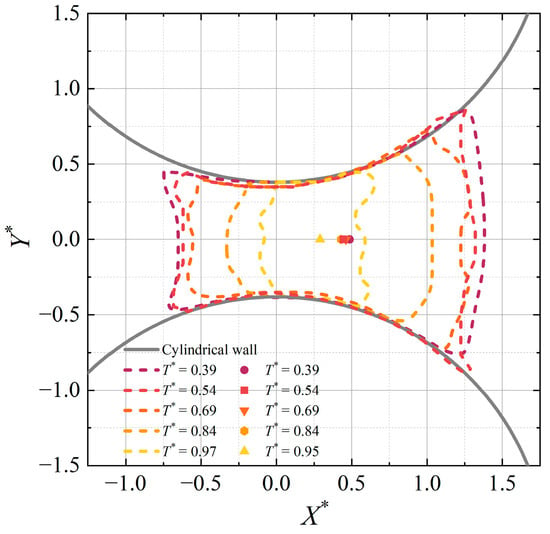
Figure 6.
The movement of the bubble contours and centroids near the double cylinders during the collapse process for case 1. l* = 0.37.
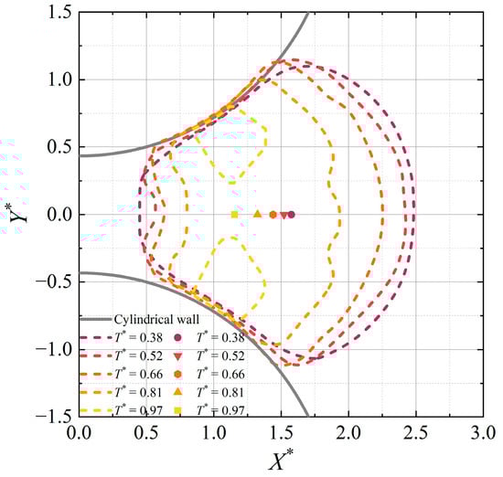
Figure 7.
The movement of the bubble contours and centroids near the double cylinders during the collapse process for case 2. l* = 1.34.
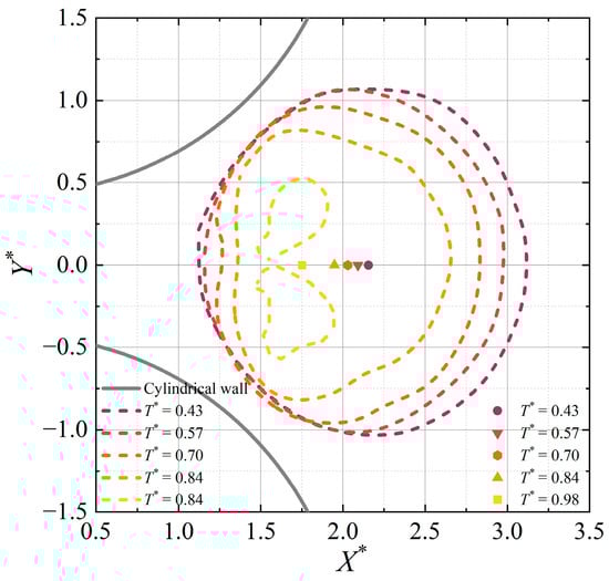
Figure 8.
The movement of the bubble contours and centroids near the double cylinders during the collapse process for case 3. l* = 1.94.
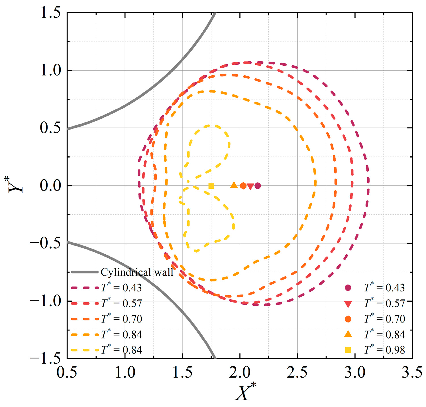
In Figure 7, during the collapse process, the upper and lower sides of the bubble still adhere to the cylinder surfaces, even after the bubble is divided into two parts. And, the contraction amplitude on the right side of the bubble interface is significantly greater than that on the left side. In addition, the bubble centroids exhibit a uniform leftward movement trend. In Figure 8, the bubble interface does not come into contact with the cylinder surfaces, and the contraction amplitude on the left side of the bubble interface is the smallest. In the final stage of the collapse, the spacing between the two parts of the bubble is relatively small, and a collapse jet is generated.
In general, as l* increases, the contraction amplitude on the left side of the bubble interface decreases. The movement amplitude of the bubble centroid increases in the early stage of the collapse and decreases in the later stage. It can be considered that the inhomogeneity of the pressure around the bubble is the main reason for the bubble centroid movement and deformations. Specifically, when the bubble oscillates freely, the pressure of the surrounding liquid decreases due to its contraction motion during the collapse process. And, a rigid wall nearby results in a higher liquid pressure between it and the bubble than in other areas. Thus, as l* increases, the bubble moves from between the two cylinders to the position on the right side of them, and the pressure on the left bubble interface increases. In addition, the condition for generating a collapse jet is that the abscissa of the bubble (i.e., l*) is relatively large. At this point, the contraction amplitude on the left side is much smaller than that on the right side. Therefore, a significant depression is formed on the right side, gradually developing into a collapse jet.
Furthermore, the movement characteristics of points A (left endpoint) and B (right endpoint) on the bubble interface are presented in detail. Figure 9 shows high-speed photographic composite images of points A and B on the bubble interface over time. The time period exhibited in the figure is the first bubble oscillation period (i.e., T* = 0~1). The faint lines inside and outside the bubble were caused by tiny bubbles and droplets. As shown in Figure 9, the movement rates of points A and B during the bubble growth process were both greater than those during the collapse process. When l* is small (i.e., Figure 9a), the composite image is basically symmetrical, indicating that the difference in the movement of two points is small. As l* increases, the movement distance of point A decreases, while that of point B increases, resulting in the bottom of the composite images tilting to the left. In addition, blank areas appear at the bottom of the composite image before reaching T* = 1, as the bubble is divided into two parts in the final stage of the collapse. This phenomenon appears as l* increases, then gradually diminishes.
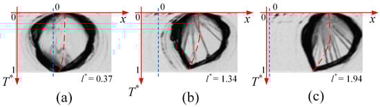
Figure 9.
High-speed photographic composite images of the points A (left endpoint) and B (right endpoint) on the bubble interface over time. (a) l* = 0.37. (b) l* = 1.34. (c) l* = 1.94. The blue dashed lines represent the position where x = 0. The red dashed lines represent the position of the bubble centroids.
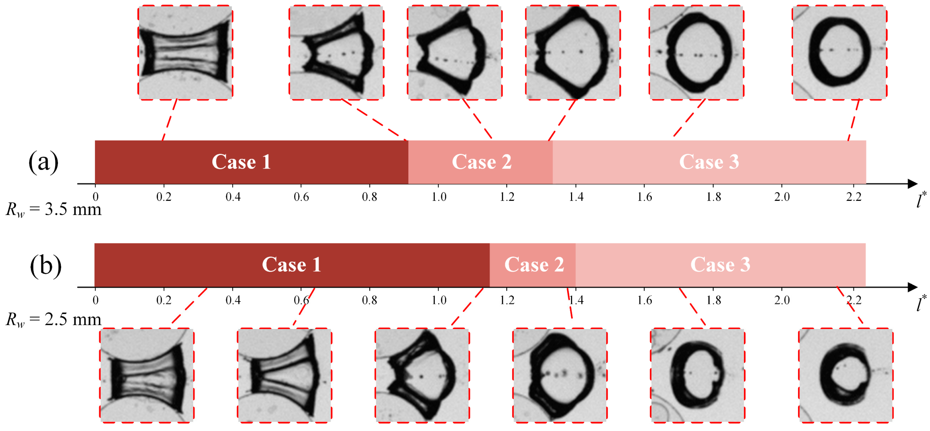
Subsequently, based on a large amount of experimental data, parameter identification criteria were established for the three cases, considering two cylindrical radii. Figure 10 shows the parameter identification criteria for the three cases. The images are photographs of the typical bubble deformations at different values of l*. In the figure, when the cylinder radius is 3.5 mm (i.e., Figure 10a), l* < 0.90 for case 1, 0.90 < l* < 1.35 for case 2, and l* > 1.35 for case 3. When the cylinder radius was 2.5 mm (i.e., Figure 10b), l* < 1.15 for case 1, 1.15 < l* < 1.40 for case 2, and l* > 1.40 for case 3. In general, as the cylinder radius increased, the transition values of l* for the three cases decreased, and the parameter intervals for cases 1 and 2 also decreased.
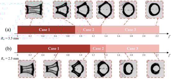
Figure 10.
Parameter identification criteria for three cases. The images are photographs of the typical bubble deformations at different values of l*. (a) Rw = 3.5 mm. (b) Rw = 2.5 mm.
4. Quantitative Analysis of the Bubble’s Behaviors
In this section, the bubble deformations and centroid movements are quantitatively analyzed. The influence mechanism of the bubble position is demonstrated through the characteristics of the bubble roundness and the duration of the first oscillation period.
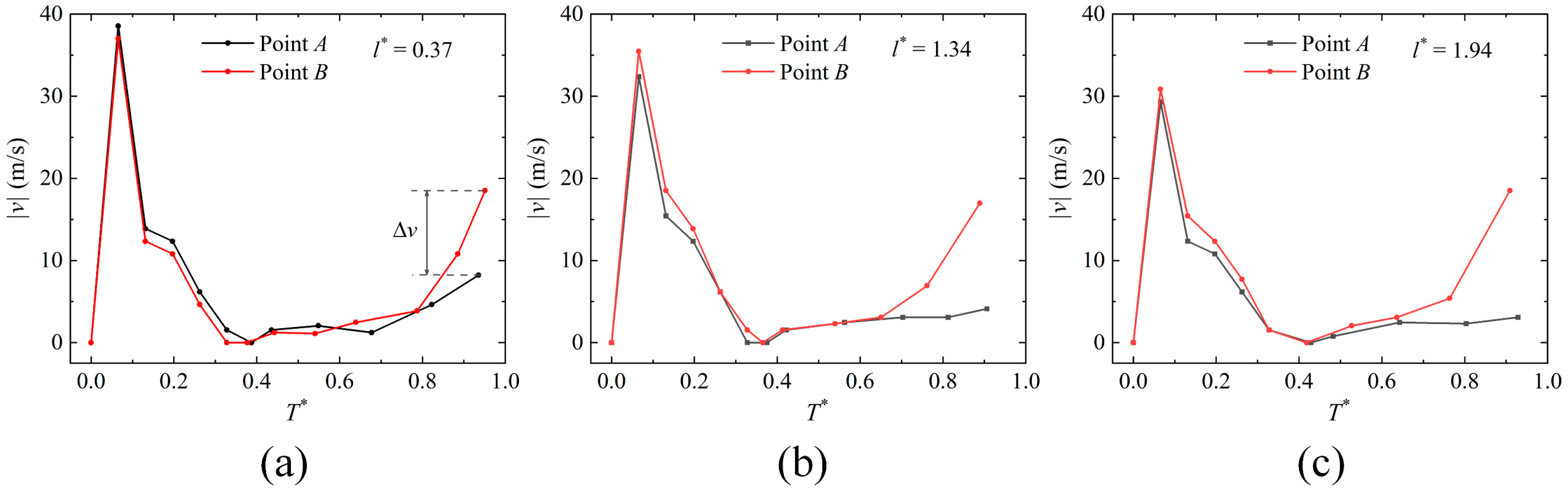
Figure 11 shows the variations in the bubble interface velocities at points A (vA) and B (vB) on the bubble interface over time during the collapse process. ∆v is the difference between vA and vB in the final stage of the collapse. In the figure, during the bubble growth process, both vA and vB increase rapidly to a peak and then decrease to zero. The maximum values of vA and v both decrease as l* increases. Then, in the early stage of the collapse (i.e., T* = 0.4~0.65), the variations in vA and vB with T* are very small, and the difference between them is also small. Specifically, when l* is small (i.e., Figure 11a), vB is smaller than vA. And, as l* increases, vB gradually becomes larger than vA. As the collapse progresses, both vA and vB increase, and the variation in vB with T* is much greater than that of vA. In addition, under different l*s, there is not much difference in vB, and the variation trends are also similar. And, vA decreases as l* increases, which leads to a decrease in ∆v.
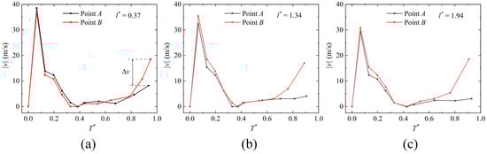
Figure 11.
Variations in the bubble interface velocities at points A (vA) and B (vB) on the bubble interface over time during the collapse process. (a) l* = 0.37. (b) l* = 1.34. (c) l* = 1.94.
The roundness (ϕ) of the bubble cross-section is also an important parameter describing the deformation characteristics, which can be expressed as follows:
Here, S is the is the area, and C is the circumference. Figure 12 shows the variations in the roundness (ϕ) of the bubble cross-section over time during the collapse process. In the figure, ϕ shows an overall trend of increasing with the increase in l*. Specifically, for case 1, in the early stage of the collapse, ϕ is very small. And, as the collapse progresses, ϕ slightly increases and reaches its peak before rapidly decreasing. For cases 2 and 3, ϕ shows a decreasing trend over time. Notably, when the bubble adheres to the cylinder surfaces (i.e., in cases 1 and 2) during the collapse process, the variation characteristics of ϕ at the end of the collapse are almost identical.
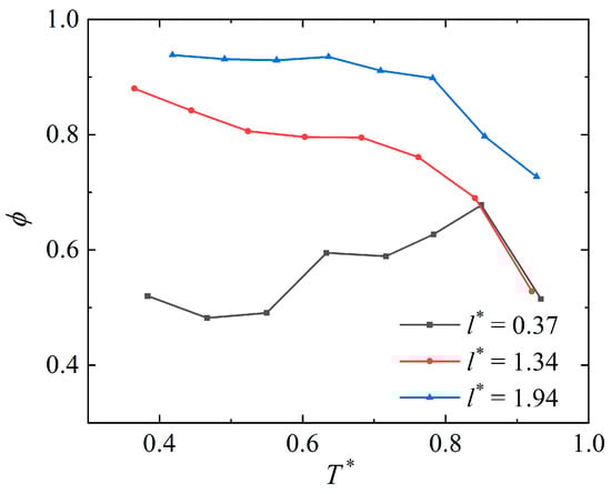
Figure 12.
Variations in the roundness (ϕ) of the bubble cross-section over time during the collapse process.
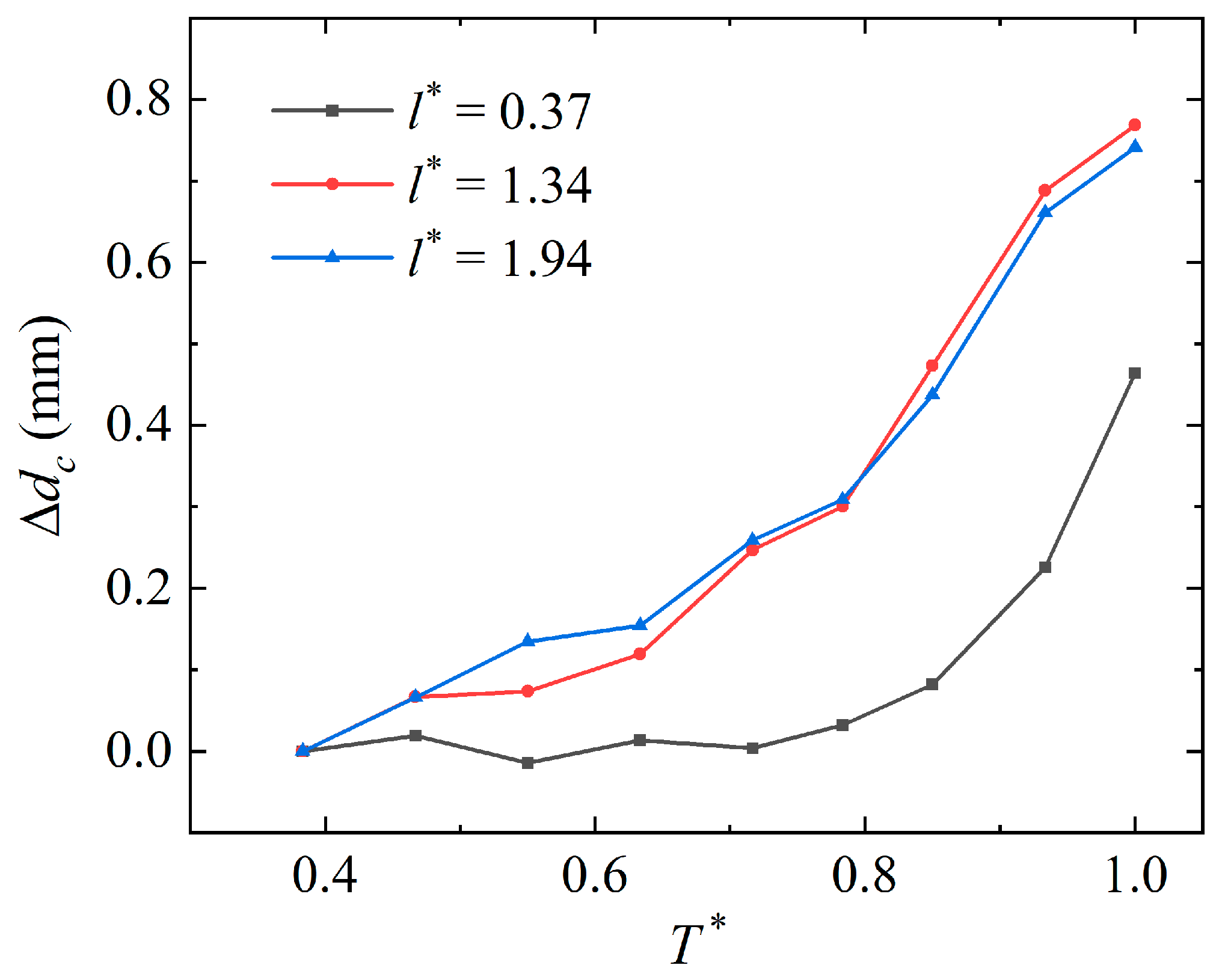
Subsequently, the characteristics of the bubble centroid movement were quantitatively analyzed. Figure 13 shows the variations in the bubble centroid moving distance (∆dc) over time during the collapse process. As shown in Figure 13, for case 1, the movement of the bubble centroid can be ignored for most of the oscillation period (T* < 0.8). And, it is pronounced in the final stage of the collapse. For cases 2 and 3, there are significant centroid movements throughout the entire collapse stage, and the trend and distance of their centroid movements are similar. In general, when a bubble collapses at the symmetrical positions of double cylinders, the bubble centroid moves toward the origin, and this phenomenon is most significant in the final stage of the collapse.

Figure 13.
Variations in the bubble centroid moving distance (∆dc) over time during the collapse process.
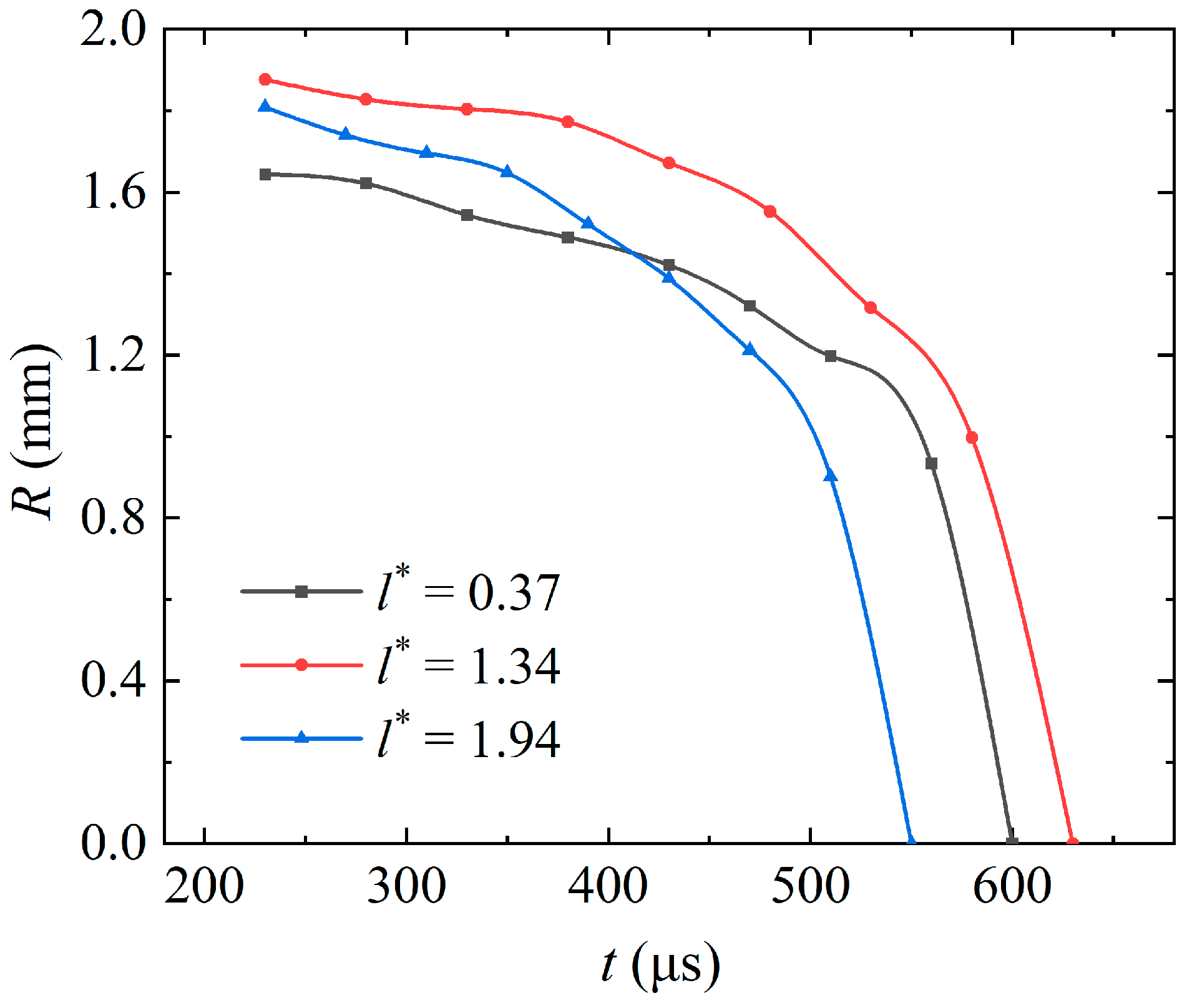
The bubble radius can be calculated by measuring its area and using the area formula, which can be expressed as follows:
Figure 14 shows the variations in the bubble radius over time during the collapse process. The maximum bubble radius (Rmax) is obtained by calculating the maximum bubble volume and then employing the cylindrical volume formula. As shown in Figure 14, the maximum bubble radii and the durations of the first oscillation period increase and then decrease as l* increases. Specifically, the minimum Rmax occurs when l* is the smallest, and the shortest bubble oscillation period occurs when l* is the largest.
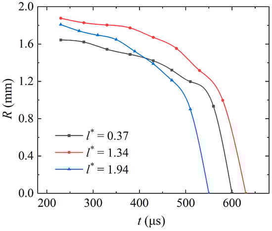
Figure 14.
Variations in the bubble radius over time during the collapse process.
5. Conclusions
In the present study, the dynamic behaviors of a bubble collapsing near double cylinders within a narrow gap were qualitatively and quantitatively investigated through a high-speed photographic technique. The mechanism by which the position of the bubble affects its dynamics were revealed. Based on a large number of experimental results, three typical collapse cases were observed and classified. In addition, the experimental bubble interface velocities, centroid movements, durations of the first oscillation period, and the roundness of the bubble cross-section were analyzed in detailed. The conclusions are summarized as follows:
(1) At the symmetrical position of the double cylinders, the bubble collapse behaviors can be divided into three typical cases based on the bubble positions: In case 1, two liquid films form inside the bubble, and the bubble interfaces on both sides contract during the collapse process. In case 2, the right half of the bubble grows inward while the right half grows in an arc shape, and the bubble is divided into two parts with a large spacing in the final stage of the collapse. In case 3, the bubble grows in a circular shape, and the bubble is also divided into two parts with a small spacing.
(2) The condition for generating a collapse jet is that the contraction amplitude on the left side of the bubble interface is much smaller than that on the right side. Thus, a significant depression is formed on the right side and gradually develops into a collapse jet.
(3) l* shows significant impacts on the bubble collapse behaviors near the double cylinders. As l* increases, the movement distance of the left endpoint on the bubble interface decreases and that of the right endpoint increases. The bubble roundness increases with increasing l*, and the duration of the first oscillation period first increases and then decreases.
In future work, it is significant to investigate the bubble dynamics in flow fields such as viscous fluids and superheated fluids [40,41]. And, numerical methods should be employed to investigate the detailed liquid flow field characteristics.
Author Contributions
Conceptualization, J.S. and Y.Z. (Yuning Zhang 1); methodology, J.S., J.Y. and S.Z.; software, J.S. and W.L.; visualization, J.Y. and S.Z.; formal analysis, W.L.; supervision, J.Y.; writing—original draft, J.S.; writing—review and editing, Y.Z. (Yuning Zhang 1) and Y.Z. (Yuning Zhang 2); project administration, Y.Z. (Yuning Zhang 1); funding acquisition, Y.Z. (Yuning Zhang 2). All authors have read and agreed to the published version of the manuscript.
Funding
This research was financially supported by the National Natural Science Foundation of China (Project No. 52076215).
Data Availability Statement
The original contributions presented in the study are included in the article, further inquiries can be directed to the corresponding author.
Acknowledgments
The authors thank the reviewers for their help with the article during its review progress.
Conflicts of Interest
The authors declare no conflicts of interest.
References
- Park, R.; Choi, M.; Park, E.H.; Shon, W.J.; Kim, H.Y.; Kim, W. Comparing cleaning effects of gas and vapor bubbles in ultrasonic fields. Ultrason. Sonochem. 2021, 76, 105618. [Google Scholar] [CrossRef] [PubMed]
- Reuter, F.; Mettin, R. Mechanisms of single bubble cleaning. Ultrason. Sonochem. 2016, 29, 550–562. [Google Scholar] [CrossRef] [PubMed]
- Chahine, G.L.; Kapahi, A.; Choi, J.K.; Hsiao, C.T. Modeling of surface cleaning by cavitation bubble dynamics and collapse. Ultrason. Sonochem. 2016, 29, 528–549. [Google Scholar] [CrossRef] [PubMed]
- Nguyen, V.T.; Phan, T.H.; Park, W.G. Modeling of shock wave produced by collapse of cavitation bubble using a fully conservative multiphase model. Phys. Fluids 2023, 35, 116102. [Google Scholar] [CrossRef]
- Kadivar, E.; Phan, T.H.; Park, W.G.; Moctar, O.E. Dynamics of a single cavitation bubble near a cylindrical rod. Phys. Fluids 2021, 33, 113315. [Google Scholar] [CrossRef]
- Sun, X.; Xia, G.; You, W.; Jia, X.; Manickam, S.; Tao, Y.; Zhao, S.; Yoon, J.Y.; Xuan, X. Effect of the arrangement of cavitation generation unit on the performance of an advanced rotational hydrodynamic cavitation reactor. Ultrason. Sonochem. 2023, 99, 106544. [Google Scholar] [CrossRef] [PubMed]
- Jin, Z.; Gao, Z.; Qian, J.; Wu, Z.; Sunden, B. A parametric study of hydrodynamic cavitation inside globe valves. J. Fluids Eng. 2018, 140, 031208. [Google Scholar] [CrossRef]
- He, Z.; Guan, W.; Wang, C.; Guo, G.; Zhang, L.; Gavaises, M. Assessment of turbulence and cavitation models in prediction of vortex induced cavitating flow in fuel injector nozzles. In. J. Multiphase Flow 2022, 157, 104251. [Google Scholar] [CrossRef]
- Dowson, D.; Taylor, C.M. Cavitation in bearings. Annu. Rev. Fluid Mech. 1979, 11, 35–65. [Google Scholar] [CrossRef]
- Blake, J.R.; Gibson, D.C. Cavitation bubbles near boundaries. Annu. Rev. Fluid Mech. 1987, 19, 99–123. [Google Scholar] [CrossRef]
- Xia, G.; You, W.; Manickam, S.; Yoon, J.Y.; Xuan, X.; Sun, X. Numerical simulation of cavitation-vortex interaction mechanism in an advanced rotational hydrodynamic cavitation reactor. Ultrason. Sonochem. 2024, 105, 106849. [Google Scholar] [CrossRef] [PubMed]
- Fu, Y.; Gao, B.; Ni, D.; Zhang, W.; Fu, Y. Study on the Influence of Thermodynamic Effects on the Characteristics of Liquid Nitrogen Cavitating Flow around Hydrofoils. Symmetry 2023, 15, 1946. [Google Scholar] [CrossRef]
- Blake, J.R.; Cerone, P. A note on the impulse due to a vapour bubble near a boundary. ANZIAM J. 1982, 23, 383–393. [Google Scholar] [CrossRef]
- Wang, X.; Wu, G.; Shen, J.; Sun, Z.; Zhang, Y.; Zhang, L.; Zhang, Y. Research on the collapse dynamics of a restricted cavitation bubble near a right-angle wall based on Kelvin impulse theory. Phys. Fluids 2023, 35, 073335. [Google Scholar] [CrossRef]
- Zhang, J.; Du, Y.; Liu, J.; Sun, Y.; Yao, Z.; Zhong, Q. Experimental and numerical investigations of the collapse of a laser-induced cavitation bubble near a solid wall. J. Hydrodyn. 2022, 34, 189–199. [Google Scholar] [CrossRef]
- Wang, Q.; Mahmud, M.; Cui, J.; Smith, W.R.; Walmsley, A.D. Numerical investigation of bubble dynamics at a corner. Phys. Fluids 2020, 32, 053306. [Google Scholar] [CrossRef]
- Tagawa, Y.; Peters, I.R. Bubble collapse and jet formation in corner geometries. Phys. Rev. Fluids 2018, 3, 081601. [Google Scholar] [CrossRef]
- Takahira, H.; Fujikawa, S.; Akamatsu, T. Collapse motion of a single gas bubble near a plane or curved rigid wall. Trans. Jpn. Soc. Mech. Eng. 1989, 55, 2720–2728. [Google Scholar] [CrossRef]
- Ma, C.; Shi, D.; Chen, Y.; Cui, X.; Wang, M. Experimental research on the influence of different curved rigid boundaries on electric spark bubbles. Materials 2020, 13, 3941. [Google Scholar] [CrossRef]
- Moloudi, G.; Dadvand, A.; Dawoodian, M.; Saleki-Haselghoubi, N. Oscillation of a transient bubble near an aperture made in a convex rigid plate. Eng. Anal. Bound. Elem. 2019, 103, 51–65. [Google Scholar] [CrossRef]
- Požar, T.; Agrež, V. Laser-induced cavitation bubbles and shock waves in water near a concave surface. Ultrason. Sonochem. 2021, 73, 105456. [Google Scholar] [CrossRef]
- Ma, C.; Shi, D.; Li, C.; Wang, M.; He, D. Experimental research on the electric spark bubble load characteristics under the oblique 45 degree curved surface boundary. J. Mar. Sci. Eng. 2020, 9, 32. [Google Scholar] [CrossRef]
- Li, S.; Zhang, A.; Han, R. Counter-jet formation of an expanding bubble near a curved elastic boundary. Phys. Fluids 2018, 30, 121703. [Google Scholar] [CrossRef]
- Shen, J.; Li, S.; Wang, X.; Zhang, Y.; Xian, H.; Zheng, S.; Zhang, Y. Theoretical and experimental investigation of a bubble collapsing near an asymmetric hydrofoil. Phys. Fluids 2024, 36, 023362. [Google Scholar] [CrossRef]
- Pendar, M.R.; Alavi, A.; Roohi, E. Identification of frequency modes and spectral content for noise suppression, Cavitation flow over 3-D hydrofoil with sinusoidal leading edge. Int. J. Mod. Phys. C 2023, 34, 2350074. [Google Scholar] [CrossRef]
- Yang, Q.; Li, D.; Xiao, T.; Chang, H.; Fu, X.; Wang, H. Control mechanisms of different bionic structures for hydrofoil cavitation. Ultrason. Sonochem. 2024, 102, 106745. [Google Scholar] [CrossRef] [PubMed]
- Hu, J.; Li, X.; Zhu, J.; Ning, X.; Wan, Q.; Lin, C. Effect of cavitation on fluid-structure interaction of a cantilever hydrofoil. Ocean Eng. 2023, 288, 116025. [Google Scholar] [CrossRef]
- Tavakoli, A.; Roohi, E.; Namaghi, M.S. Numerical simulation of free surface water waves around wavy hydrofoils, Prediction of hydrodynamic coefficients using machine learning. J. Fluids Eng. 2024, 146, 021501. [Google Scholar] [CrossRef]
- Wang, X.; Wu, G.; Zheng, X.; Du, X.; Zhang, Y.; Zhang, Y. Theoretical investigation and experimental support for the cavitation bubble dynamics near a spherical particle based on Weiss theorem and Kelvin impulse. Ultrason. Sonochem. 2022, 89, 106130. [Google Scholar] [CrossRef]
- Zhang, Y.; Ding, Z.; Hu, J.; Zheng, X.; Yu, J.; Hu, J. Theoretical investigation on the cavitation bubble dynamics near three spherical particles based on Weiss theorem. J. Hydrodyn. 2024, 35, 1119–1130. [Google Scholar] [CrossRef]
- Wu, S.; Li, B.; Zuo, Z.; Liu, S. Dynamics of a single free-settling spherical particle driven by a laser-induced bubble near a rigid boundary. Phys. Rev. Fluids 2021, 6, 093602. [Google Scholar] [CrossRef]
- Li, S.; Zhang, A.; Han, R.; Ma, Q. 3D full coupling model for strong interaction between a pulsating bubble and a movable sphere. J. Comput. Phys. 2019, 392, 713–731. [Google Scholar] [CrossRef]
- Li, S.; Han, R.; Zhang, A. Nonlinear interaction between a gas bubble and a suspended sphere. J. Fluids Struct. 2016, 65, 333–354. [Google Scholar] [CrossRef]
- Zhang, A.; Li, S.; Cui, P.; Li, S.; Liu, Y. A unified theory for bubble dynamics. Phys. Fluids 2023, 35, 033323. [Google Scholar] [CrossRef]
- Best, J.P.; Blake, J.R. An estimate of the Kelvin impulse of a transient cavity. J. Fluid Mech. 1994, 261, 75–93. [Google Scholar] [CrossRef]
- Wang, Z.; Yang, Y.; Guo, Z.; Hu, Q.; Wang, X.; Zhang, Y.; Li, J.; Zhang, Y. Experimental Investigations on the Cavitation Bubble Dynamics near the Boundary of a Narrow Gap. Symmetry 2024, 16, 541. [Google Scholar] [CrossRef]
- Quinto-Su, P.A.; Lim, K.Y.; Ohl, C.D. Cavitation bubble dynamics in microfluidic gaps of variable height. Phys. Rev. E. 2009, 80, 047301. [Google Scholar] [CrossRef] [PubMed]
- Braun, M.J.; Hendricks, R.C. An experimental investigation of the vaporous/gaseous cavity characteristics of an eccentric journal bearing. ASLE Trans. 1984, 27, 1–14. [Google Scholar] [CrossRef]
- El Ashmawy, M.; Murrenhoff, H. Experimental investigation of friction force between vane tip and cam-ring in oil vane pumps. Int. J. Fluid Power 2009, 10, 37–46. [Google Scholar] [CrossRef]
- Mohammadein, S.A.; Abu-Bakr, A.F. The growth of vapour bubble in a superheated liquid between two phase turbulent flow. Can. J. Phys. 2010, 88, 317–324. [Google Scholar] [CrossRef]
- Shalaby, G.A.; Abu-Bakr, A.F. Growth of N-dimensional spherical bubble within viscous, superheated liquid: Analytical solution. Therm. Sci. 2021, 25, 503–514. [Google Scholar] [CrossRef]


Disclaimer/Publisher’s Note: The statements, opinions and data contained in all publications are solely those of the individual author(s) and contributor(s) and not of MDPI and/or the editor(s). MDPI and/or the editor(s) disclaim responsibility for any injury to people or property resulting from any ideas, methods, instructions or products referred to in the content. |
© 2024 by the authors. Licensee MDPI, Basel, Switzerland. This article is an open access article distributed under the terms and conditions of the Creative Commons Attribution (CC BY) license (https://creativecommons.org/licenses/by/4.0/).