Abstract
Traditional methods for monitoring the foundation settlement of airport runways predominantly employ equipment such as leveling instruments, total stations, layered settlement instruments, magnetic ring settlement instruments, ground-penetrating radar (GPR), and synthetic aperture radar. These methods suffer from low automation levels, are time-consuming, labor-intensive, and can significantly disrupt airport operations. An alternative electromagnetic detection technique, Controlled Source Audio-Frequency Magnetotellurics (CSAMT), offers deep-depth detection capabilities. However, CSAMT faces significant challenges, particularly in generating high signal-to-noise ratio (SNR) signals in the far-field region (FfR). Traditional CSAMT utilizes grounded horizontal dipoles (GHDs), which radiate symmetric beams. Due to the low directivity of GHDs, only a small fraction of the radiated energy is effectively utilized in FfR observations. Enhancing the SNR in FfR typically requires either reducing the transceiving distance or increasing the transmitting power, both of which introduce substantial complications. This paper proposes an airborne-dangled monopole-antenna symmetric remote-sensing radiation source for airport runway monitoring, which replaces the conventional GHD. The analytical, simulation, and experimental verification results indicate that the energy required by the airborne-dangled symmetric source to generate the same electric field amplitude in the FfR is only one-third of that needed by traditional CSAMT. This results in significant energy savings and reduced emissions, underscoring the advantages of the airborne-dangled monopole-antenna symmetric source in enhancing energy efficiency for CSAMT. The theoretical analysis, simulations, and experimental results consistently verify the validity and efficacy of the proposed airborne-dangled monopole-antenna symmetric remote-sensing radiation source in CSAMT. This innovative approach holds substantial promise for airport runway monitoring, offering a more efficient and less intrusive solution compared to traditional methods.
1. Introduction
The airport runway foundation serves as a critical support structure for the airport pavement infrastructure []. Influenced by factors such as the initial surface conditions, depth of foundation fill, construction quality, and hydrogeological conditions [,], the foundation undergoes differential settlement post construction [,]. This differential settlement diminishes the foundation’s load-bearing capacity on the pavement structure [,], leading to localized stress and strain increases that can manifest as runway cracking, joint damage, misalignment, and ultimately reduce the runway’s operational lifespan, posing significant safety risks to aircraft operations during taxiing [,,]. Therefore, the precise monitoring of foundation settlement, the accurate prediction of its developmental trends, and scientific evaluation, are imperative.
Traditional methods for monitoring foundation settlement predominantly rely on equipment such as leveling instruments [,], total stations [], and ground-penetrating radar (GPR) [,,], involving manual point measurements. These methods exhibit low levels of automation, are time-consuming, labor-intensive, and can disrupt airport construction operations [,]. Real-time settlement data for individual foundation layers can be obtained using instruments like layered settlement devices [] and magnetic ring settlement instruments []. However, sensor burial processes are complex [], and installation costs are high [], making these methods suitable primarily for monitoring settlement at select representative points []. Emerging technologies like synthetic aperture radar interferometry provide settlement information across entire airport areas without surface interference but are challenged in capturing ground settlement data beneath pavement structures [,,]. Electromagnetic methods, such as Controlled Source Audio-Frequency Magnetotellurics (CSAMT), offer capabilities for relatively deep subsurface exploration, though they encounter technical limitations.
Traditional CSAMT, derived from audio-frequency magnetotellurics (AMT) [,,,], employs a grounded horizontal dipole (GHD) as a transmitting source [,]. The electromagnetic fields generated by this GHD source are recorded through AMT in the far-field region (FfR) (, where r is the distance between the transmitter and the receiver, and is the skin depth) []. During CSAMT surveys, the GHD is horizontally buried in shallow crust, with the receiver positioned directly above the measurement point in the FfR [,,]. Studies indicate that the horizontal polarization wave in the earth exhibits significantly higher attenuation (Ah) compared to the vertical polarization wave (Av) [,,,,], rendering the GHD nearly omnidirectional and inefficient in energy utilization []. Achieving a satisfactory signal-to-noise ratio (SNR) at the receiver necessitates higher transmitter power or shorter transceiver distances due to the dispersed nature of energy radiated by the GHD []. Increasing transmitter power faces various electrical constraints, with higher power levels adversely impacting field exploration due to increased equipment size [,]. Conversely, reducing transceiver distance introduces complexities related to field source effects, complicating CSAMT data interpretation and often leading to erroneous geological inferences, thereby affecting practical CSAMT applications [,]. In summary, neither method adequately addresses the challenge of enhancing signal strength or SNR at the receiver.
This study proposes an enhanced airborne-dangled CSAMT (AD-CSAMT) approach to achieve the comprehensive monitoring of longitudinal or transverse ground settlement across airport runways. AD-CSAMT mitigates the conventional CSAMT limitations associated with high power transmission and path losses, enabling deep subsurface monitoring and delivering high SNR at the receiver. This innovative approach offers a new solution for addressing ground settlement issues on airport runways.
2. Principle and Methods of AD-CSAMT
2.1. Skin Depth Equation
Skin depth is a key factor in measuring the depth of electromagnetic detection in the frequency domain []. It is defined based on the propagation characteristics of electromagnetic waves []. In the FfR, when an electromagnetic wave at a certain frequency propagates within the range of half space, the ratio of the amplitude value of the electromagnetic wave at a certain point on the surface to the amplitude value of the electromagnetic wave at that depth is e, and the depth at this point is the skin depth of the electromagnetic wave at that frequency []. The expression is:
In Equation (1), represents the skin depth, represents the resistivity, f represents the frequency of electromagnetic waves, and represents the wavelength of electromagnetic waves [].
In electromagnetic detection, skin depth is a very important parameter that reflects the depth of electromagnetic detection []. It is generally used in the inversion of CSAMT electromagnetic detection data. Research has shown that under different electromagnetic field components, there is a correlation between the effective skin depth and the variation trend in the electrical conductivity of the formation, the frequency of electromagnetic waves emitted, and the distance between transmission and reception []. According to the formula for estimating effective skin depth, it is possible to calculate the effective skin depth under any condition, which can provide effective guidance for field work.
2.2. Cagniard Apparent Resistivity Equation
In the basic theory of CSAMT, the Cagniard apparent resistivity formula derived from uniform ground is generally applied in the calculation of apparent resistivity []. In the FfR, electromagnetic waves enter the earth in a plane-like wave state, and the Cagniard apparent resistivity can objectively reflect the vertical changes in the geoelectric cross-section []; in the near and transition regions, there will be severe distortions that cannot reflect the geoelectric cross-section, which is known as the near-field effect [].
In this article, the study focuses on how to improve the energy utilization efficiency of CSAMT when measuring in the FfR, so the Cagniard apparent resistivity calculation formula is applicable to this study. Although, in actual field exploration, due to limitations in transmission power, work area conditions, and other factors, measurements may enter the near zone or transition zone. In this case, it is necessary to correct the calculation formula. When conducting measurements, the electric field component and the orthogonal horizontal magnetic field component at the corresponding frequency are measured one by one at the measurement point, and the Kanya apparent resistivity and impedance phase are calculated []. The formula is:
In Equation (2), is the magnetic permeability; ; f is the frequency; is the phase of the magnetic field component ; is the phase of electric field component . Scanning from high to low frequency can obtain the variation characteristics of Kanya apparent resistivity with frequency, thus achieving frequency sounding observation [].
2.3. Radiation Characteristics
In traditional CSAMT, a GHD is used as a transmitter. Because the receiver is located far from the transmitter, the GHD can be considered as a point source with practically no directionality [,], assuming that a diploe of finite-length l is placed in the air and the current distribution on the wire is sinusoidal [], as shown in Figure 1.

Figure 1.
Radiation field on a diploe. (a) . (b) θ′ ≈ θ.
As shown in Figure 2, () is the position of the source, represents the distance from the source to the observation point, and represents the unit vector along the z-axis. The current density can be written as:
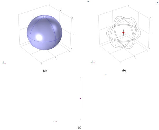
Figure 2.
The air domain (a), the dipole antenna (b) and the lumped port model (c).
The micro-element on the diploe can be divided into many small dipoles of length . The radiation of a small dipole in the FfR can be written as follows:
where R is the distance between the current micro-element and the observation point. Because we are focusing on the FfR radiation characteristics of the diploe, we can assume that , θ′ ≈ θ [].
The electric field can thus be written as:
After integration, we obtain:
After calculation, we can derive:
Therefore, the Poynting vector () is:
The radiation intensity is:
The power density can be integrated along the radial direction []. Therefore, the radiated power along the radial direction is:
When is close to 1, we obtain:
The direction factor can thus be written as:
3. Simulation of a Dipole and Its Application in CSAMT
3.1. Simulation of a Dipole
The previous section analyzed the radiation field calculation of finite-length dipole antennas. This section mainly discusses the radiation characteristics of uniform full-space finite-length dipole antennas. In order to observe the radiation characteristics more intuitively, a uniform full-space finite-length dipole antenna model is first established in COMSOL. As shown in Figure 2a, the model is the air domain with , and 0 Sm−1, and the free space wavelength at the dipole’s operating frequency is 4 m. Thus, in order to achieve a wavelength of 75 MHz, the dipole’s arm is 1 m long and aligned with the z-axis, which can be seen in Figure 2b. The arm radius is chosen to be 0.025 m.
Figure 2c shows a finite-length dipole antenna model, which mainly consists of three parts: two long conductors and a lumped port. When the finite-length dipole antenna operates, AC excitation is applied from the central lumped port.
At the outset of operations, a sinusoidal AC signal of 100 V amplitude is applied to the central lumped port of the dipole antenna, operating at a frequency corresponding to a wavelength of 0.074948 GHz. Figure 3 depicts the spatial distribution and vector orientation of the electric field surrounding the dipole antenna. The observed electric field pattern aligns closely with theoretical predictions, exhibiting oscillatory behavior along the longitudinal axis of the finite-length dipole antenna and gradually expanding symmetrically outward. This propagation pattern underscores the antenna’s characteristic radiation properties as governed by electromagnetic field theory.
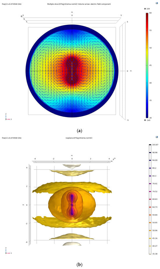
Figure 3.
Section diagram of the magnitude and direction of the electric field around the dipole antenna. (a) multiple slice(xz-axis) of electric field, (b) three dimensional isoplane of electric field.
Figure 4 depicts the two-dimensional directional pattern of a uniform full-space finite-length dipole antenna. The radiation beam exhibits symmetric distribution along the axis of the finite-length dipole antenna, extending on both sides with mild directional characteristics. From the perspective of the magnetic field surface, the directional pattern appears nearly circular. Conversely, from the electric field surface perspective, it demonstrates axisymmetric behavior, diverging on both sides and forming a concave shape in the center. These findings align with the radiation properties of finite-length dipole antennas discussed in the preceding section, particularly in the context of FfR analysis.
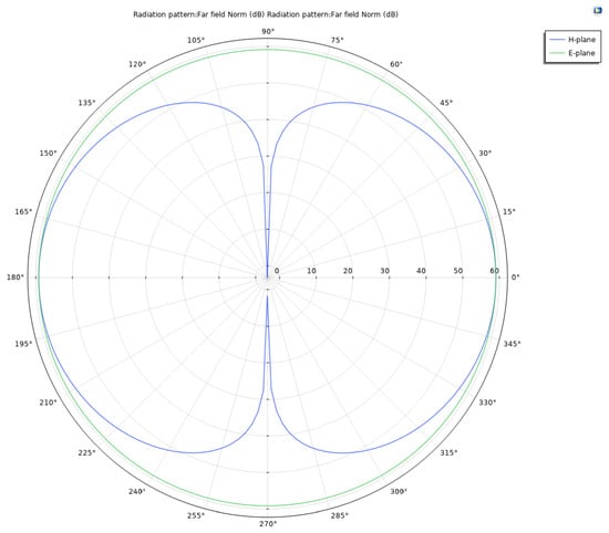
Figure 4.
The polar plot of the FfR pattern in the xy-plane is omni-directional.
The polar plot in Figure 4 illustrates the directional pattern in the xy-plane, while Figure 5 provides a three-dimensional visualization of the radiation intensity distribution in the far-field region. Both representations affirm the anticipated omnidirectional radiation pattern characteristic of the dipole antenna under study.
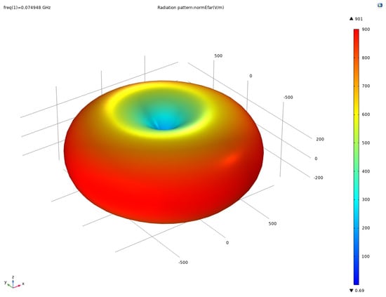
Figure 5.
A 3D visualization of the FfR pattern of the dipole shows the expected omni-directional pattern.
As previously discussed, the two-dimensional pattern reveals a nearly circular shape on the magnetic field surface, whereas the electric field surface exhibits axisymmetric divergence, with concavity in the center and divergence on both sides. This observation aligns with the expected radiation characteristics of finite-length dipole antennas analyzed earlier.
Figure 5 illustrates a three-dimensional pattern that comprehensively validates the conclusions drawn from the two-dimensional analysis. It provides empirical evidence supporting the radiation principles of finite-length dipole antennas through rigorous physical processes and simulations. The confirmation of these patterns underscores the reliability and applicability of theoretical models in antenna design and electromagnetic field analysis.
3.2. Application of Dipole in CSAMT
CSAMT experiments involve deploying a GHD transmitter, which emits low-frequency electromagnetic signals into the subsurface. These signals propagate through geological formations characterized by varying resistivity distributions. Positioned at a designated distance, a receiver captures the induced voltage responses across a range of frequencies. The collected data undergo rigorous processing to derive parameters such as apparent resistivity and phase, which provide critical insights into the electrical properties of subsurface structures. CSAMT methodology facilitates deep exploration capabilities beyond the reach of conventional techniques, making it indispensable for geophysical surveys, mineral prospecting, and infrastructure evaluations, where precise characterization of subsurface conditions is paramount.
In order to provide a more intuitive explanation of the radiation characteristics of a single electric dipole artificial field source placed on a uniform half-space surface in CSAMT, a half-space model with analytical solutions was established in the COMSOL software (the version 5.6) environment, as shown in Figure 6. The model is a sphere with a radius of 30 km. The upper half of the space is air (, and 0 Sm−1); the lower part of the space consists of soil (, and 0.01 Sm−1).
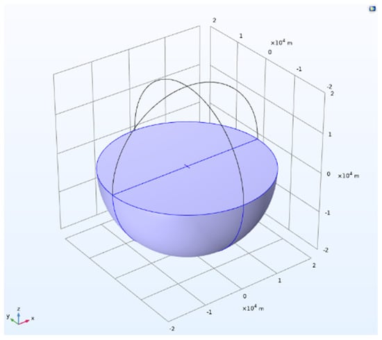
Figure 6.
A single electric dipole artificial field source on the surface of a uniform half-space.
An electric dipole artificial field source with an arm length of 1 km is placed on the ground in the model, as the arm length is too long and can only be installed horizontally. According to the formula (where V is the propagation speed of electromagnetic waves in Earth, C is the propagation speed of electromagnetic waves in vacuum, is the relative permittivity of soil, and is the relative magnetic permeability of soil), the working frequency of CSAMT is generally about 0.1 Hz–10 kHz, and the working frequency of this model is selected as 100 Hz. The arm radius of this model is 0.05 m, the gap between two wires is 0.1 m, and the excitation applied to the dipole antenna is a current dipole moment of 15 A·m.
Figure 7 depicts the electric field distribution and contour lines of a single electric dipole artificial field source as observed from a top-down perspective. The illustration aligns with the analysis of radiation characteristics presented in Section 3.1 for a uniform full-space finite-length dipole antenna. The electric field exhibits linear polarization with outward propagation, accompanied by a gradual attenuation in amplitude. This observation underscores the consistency and applicability of theoretical insights to the behavior of dipole antennas in electromagnetic field propagation scenarios.
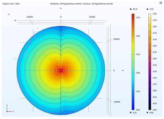
Figure 7.
The electric field distribution and contour lines of a single electric dipole artificial field source viewed from the z-axis.
As depicted in Figure 8, the axial view illustrates the configuration of an artificial field source generated by a single electric dipole antenna. The depiction delineates the upper half-space as the atmospheric domain, representing air, while the lower half-space denotes the subterranean domain, representing the earth’s medium. The visual representation underscores a conspicuous observation: electromagnetic wave attenuation within the soil medium is markedly more pronounced compared to propagation through the atmospheric medium. Moreover, the figure highlights that the propagation distance of electromagnetic waves in soil is substantially curtailed relative to their propagation in air. These phenomena are intricately linked to the distinct electromagnetic properties intrinsic to the earth’s medium, as substantiated by established principles in electromagnetic field theory [].
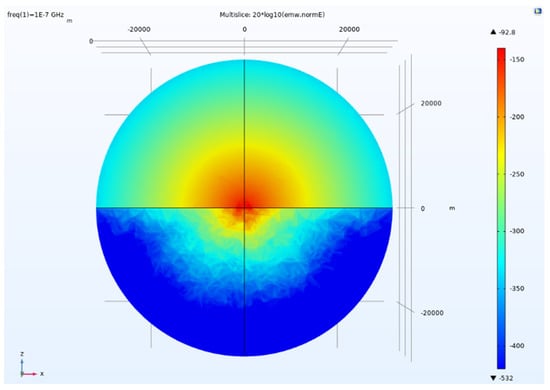
Figure 8.
The axial view of the artificial field source of a single electric dipole antenna.
The energy captured in the FfR within a 60° angle on the side is quite low. The electric field values (from 1000 m to 10,000 m) were extracted using the electric field value probe tool in COMSOL software, as shown in Table 1.

Table 1.
Electric field value of from 1 km to 10 km at frequency of 100 Hz (current dipole moment amplitude: 15 A·m).
Table 1 shows the electric field values from 1000 m to 10,000 m; with an electric field value of 3.59 × 10⁻⁷ V/m at 1000 m, the electric field value becomes 7.33 × 10⁻⁹ V/m at 5000 m, reduced by about 49 times, and as the distance increases, the electric field value at 10,000 m decreases again to 1.02 × 10⁻¹⁰ V/m, compared to the electric field value at 1000 m, which reduces by about 3519 times. It can be seen that as the distance increases, the amplitude level of the collected electric field decreases rapidly. When measuring in the FfR, if there are interference signals in the environment that are difficult to filter out, the SNR of the collected data will be seriously affected.
From Figure 9, it can be seen that as the distance increases, the amplitude level of the collected electric field decreases rapidly. When measuring in the far-field area, if there are interference signals in the environment that are difficult to filter out, the SNR of the collected data will be seriously affected.
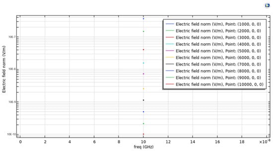
Figure 9.
Electric field value of from 1 km to 10 km at frequency of 100 Hz.
4. Simulation of an Airborne-Dangled Monopole-Antenna Symmetric Remote-Sensing Radiation Source and Its Application in CSAMT
The divergence in radiation characteristics between dipole and monopole antennas hinges on their directional properties and suitability for specific deployment scenarios. A dipole antenna radiates a full 360-degree signal in the horizontal plane, accompanied by variable vertical emission angles. In contrast, the vertical radiation pattern of a monopole antenna closely resembles that of a half-wave dipole antenna vertically, albeit without ground plane radiation which is not what we need.
On the horizontal plane, a vertical monopole antenna exhibits omnidirectional radiation characteristics, offering uniform signal coverage in all directions. Given the constraints of airborne-dangled installations, where providing intermediate feeding for dipole antennas poses challenges, the radiation properties of a monopole antenna are preferred. This selection ensures practical deployment and effective performance within the operational parameters specified.
4.1. Simulation of an Airborne-Dangled Monopole-Antenna Symmetric Remote-Sensing Radiation Source
Figure 10 revealed an airborne-dangled monopole-antenna symmetric remote-sensing radiation source model, which consists of sphere models with a radius of 500 m. The upper half-space of the models is the air domain, the parameter settings of which are consistent with Figure 2; the lower half-space of the models is a soil domain with , and . In Figure 10, an airborne-dangled monopole-antenna symmetric remote-sensing radiation source model with a 25 m length and a 0.0125 m radius is depicted, which is perpendicular to the surface of a uniform half-space.
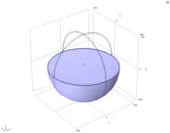
Figure 10.
An airborne-dangled monopole-antenna symmetric remote-sensing radiation source model perpendicular to the surface of a uniform half-space.
Figure 11 illustrates the cross-sectional view of the electric field and the orientation of both electric and magnetic fields generated by an airborne-dangled monopole antenna serving as a symmetric remote-sensing radiation source. The electric field direction, denoted by the red arrow and aligned parallel to the monopole antenna, is perpendicular to the Earth’s surface and lies within the same plane as the directional axis of the airborne-dangled monopole antenna’s symmetric remote-sensing radiation source, thereby confirming the vertical polarization of electromagnetic waves. This polarization phenomenon is similarly evident in the orientation of the magnetic field. Represented by the blue arrow and perpendicular to the monopole antenna, the magnetic field direction is orthogonal to the electric field direction, indicating that the magnetic field is perpendicular to the plane of the airborne-dangled radiation source. These observations underscore the distinctive polarization characteristics and spatial alignment of electromagnetic fields emitted by the monopole antenna in the context of remote sensing applications.
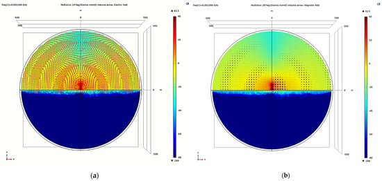
Figure 11.
The direction of the electric field is perpendicular to the ground (a); the direction of the magnetic field is parallel to the ground (b).
Figure 12 illustrates the orientation of the Poynting vector, which defines the direction of electromagnetic wave propagation. The airborne-dangled monopole antenna serving as a symmetric remote-sensing radiation source is depicted as a point source, from which electromagnetic waves propagate outward. This observation underscores the characterization of the antenna as a focal point for radiative emissions, emphasizing the directional emission of electromagnetic energy in the surrounding space. Such a visualization is crucial for understanding the spatial dynamics and propagation characteristics of electromagnetic waves emitted by the monopole antenna in remote sensing applications.
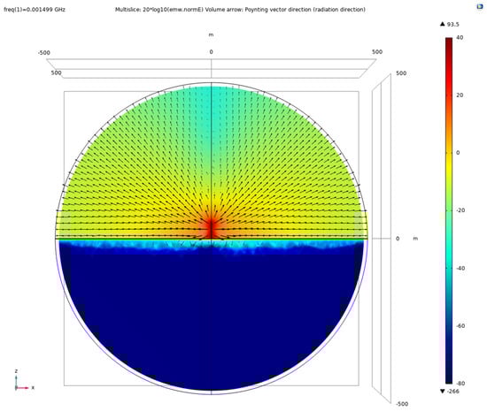
Figure 12.
Electromagnetic wave radiation direction (Poynting vector direction).
As depicted in Figure 13, the two-dimensional directional pattern illustrates the symmetric remote sensing radiation characteristics of an airborne-dangled monopole antenna. It demonstrates that, bounded by the Earth’s surface, some energy penetrates into the subsurface and propagates, while another portion propagates along the surface. This propagation behavior resembles the radiation pattern of electromagnetic waves emitted from two spatially separated columns originating from a single point source, but with varying phases due to differences in wave velocities []. This phenomenon forms the foundational basis for CSAMT exploration. Understanding these propagation dynamics is crucial for optimizing exploration methodologies and interpreting geological subsurface features in remote sensing applications.
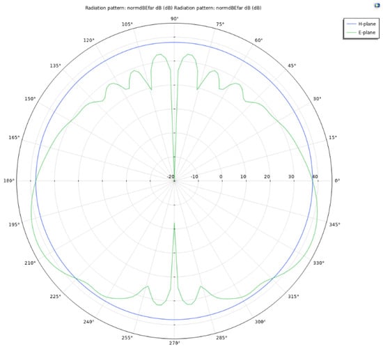
Figure 13.
The two-dimensional directional pattern of an airborne-dangled monopole-antenna symmetric remote-sensing radiation source.
The 3D visualization of the FfR intensity in Figure 14 shows the expected bowl-shaped pattern.
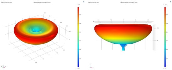
Figure 14.
The three-dimensional directional pattern of an airborne-dangled symmetric remote-sensing radiation source.
4.2. Application of an Airborne-Dangled Monopole-Antenna Symmetric Remote-Sensing Radiation Source in CSAMT
The application of an airborne-dangled monopole-antenna symmetric remote-sensing radiation source in CSAMT are shown in Figure 15, which are sphere models with radius of 30 km. The upper half-space of the models is the air domain, the parameter settings of which are consistent with Figure 2; the lower half-space of the models is a soil domain with , and .
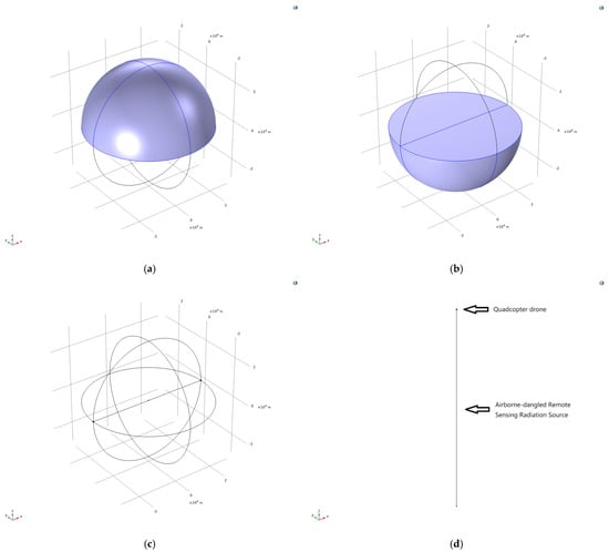
Figure 15.
Application of an airborne-dangled monopole-antenna symmetric remote-sensing radiation source in CSAMT. (a) the air domain, (b) the soil domain, (c) the application of an airborne-dangled monopole-antenna symmetric remote-sensing radiation source in CSAMT and (d) an airborne-dangled monopole-antenna symmetric remote-sensing radiation source model.
In Figure 15d, an airborne-dangled monopole-antenna symmetric remote-sensing radiation source model with a 25 m length, a 0.0125 m radius is depicted, which is perpendicular to the surface of a uniform half-space.
Figure 16 shows the axial view of the application of an airborne-dangled monopole-antenna symmetric remote-sensing radiation source in CSAMT. The upper half-space is the air domain, and the lower half-space is the earth. Consistent with traditional CSAMT, the attenuation of electromagnetic waves propagating in soil is significantly higher than those propagating in air, and the propagation distance is also much shorter. However, when observing at the same observation point and generating the same electric field amplitude, the energy required for airborne-dangled symmetric remote-sensing radiation sources is much smaller, which means that the exploration efficiency of airborne-dangled monopole-antenna symmetric remote-sensing radiation sources is higher.
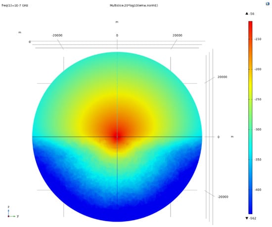
Figure 16.
The axial view of the application of an airborne-dangled monopole-antenna symmetric remote-sensing radiation source in CSAMT.
5. Discussion
The electric field values (from 1000 m to 10,000 m) were extracted using the electric field value probe tool in COMSOL software, as shown in Table 2. Table 2 shows the electric field values from 1000 m to 10,000 m, with an electric field value of 2.01 × 10⁻⁶ V/m at 1000 m, 8.57 × 10⁻⁹ V/m at 5000 m, and 1.24 × 10⁻¹⁰ V/m at 10,000 m.
Table 2.
Comparison of electric field values from 1 to 10 km under two different current dipole moments at a frequency of 100 Hz.
In comparison to traditional CSAMT, at identical observation points, the electric field amplitude remains generally within the same order of magnitude. However, the energy requirement is significantly reduced when utilizing the airborne-dangled monopole-antenna symmetric remote-sensing radiation source. Specifically, the current dipole moment introduced into the airborne remote-sensing radiation source is 5 A·m, which represents a two-thirds reduction in energy demand compared to the conventional CSAMT setup, which requires 15 A·m. This substantial decrease in energy consumption is visually represented in Figure 17, which provides an intuitive depiction similar to the data presented in Table 2.
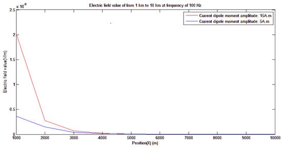
Figure 17.
Comparison of electric field values from 1 km to 10 km under two different current dipole moments at a frequency of 100 Hz.
The implications of this advancement are profound, highlighting the improved efficiency in electromagnetic field generation and propagation for subsurface exploration. By significantly reducing the energy required while maintaining comparable electric field amplitudes, the airborne-dangled monopole-antenna system demonstrates enhanced energy utilization. This improvement not only reduces operational costs and energy consumption but also minimizes the environmental impact of remote sensing activities.
Furthermore, the adoption of airborne-dangled monopole antennas in remote sensing applications introduces several practical advantages. The aerial deployment of the antenna allows for more flexible and precise positioning, which is particularly beneficial in challenging terrains or areas where ground access is limited. This flexibility ensures optimal data acquisition and enhances the accuracy of subsurface imaging.
The reduced energy requirement also translates to longer operational periods for airborne platforms, such as drones, thereby increasing the coverage area and the efficiency of data collection. This extended operational capability is crucial for large-scale surveys and continuous monitoring applications, where sustained performance is necessary.
In addition to the energy efficiency and practical benefits, the theoretical and experimental analyses confirm the reliability and effectiveness of the airborne-dangled monopole-antenna system. The coherence between theoretical predictions, simulation results, and experimental data underscores the robustness of this approach. This consistency is critical for validating the feasibility of using airborne-dangled monopole antennas in various remote sensing scenarios, ranging from mineral exploration to environmental monitoring. Moreover, the reduction in energy demand without compromising the quality of the electric field amplitude highlights the potential for integrating renewable energy sources into remote sensing operations. This integration could further enhance the sustainability of remote sensing projects, aligning with global efforts to reduce carbon footprints and promote green technologies.
In conclusion, the adoption of airborne-dangled monopole antennas for remote sensing applications offers significant advancements over traditional CSAMT methods. By achieving a two-thirds reduction in energy demand while maintaining effective electric field amplitudes, this innovative approach enhances the efficiency, flexibility, and sustainability of subsurface exploration. The visual representation in Figure 17, along with the data from Table 2, illustrates the practical and theoretical benefits of this technology, solidifying its potential for widespread adoption in various remote sensing and monitoring applications.
6. Experimental Verification
A monopole antenna is a type of vertical antenna characterized by its length, which is typically a quarter of the wavelength of the frequency it is designed to transmit or receive. This antenna configuration necessitates the presence of a ground plane to function effectively, which can be either the actual physical ground or an artificial surface designed to simulate the ground, such as metal plates or carrying tools. In the context of this project, the monopole antenna is innovatively suspended and installed using a drone, as illustrated in Figure 18.
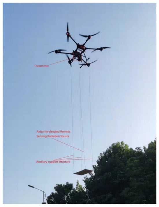
Figure 18.
The experimental verification platform of the airborne-dangled monopole-antenna remote-sensing radiation source.
The use of a drone to deploy the monopole antenna introduces several advantages and considerations. First, the aerial installation allows for greater flexibility in positioning the antenna, enabling optimal placement to achieve the best possible signal reception and transmission. This flexibility is particularly beneficial in environments where the ground conditions are unsuitable or where mobility is required to cover a wide area. Additionally, the drone’s mobility facilitates the rapid deployment and repositioning of the antenna, which can be crucial in dynamic monitoring scenarios such as airport runway surveillance.
Moreover, suspending the monopole antenna from a drone minimizes the potential interference from nearby objects or structures that could affect the antenna’s performance. By elevating the antenna above ground level, the drone reduces the risk of signal obstruction and enhances the clarity and strength of the received signals. This setup also allows for the creation of a controlled and consistent measurement environment, as the drone can maintain a stable altitude and orientation, ensuring that the antenna operates under optimal conditions.
The integration of drone technology with monopole antennas represents a significant advancement in remote sensing and monitoring applications. The drone serves as both a deployment platform and a means of enhancing the antenna’s operational capabilities, providing a versatile and efficient solution for various monitoring tasks. The combination of these technologies can lead to improved accuracy and reliability in data collection, as well as increased efficiency in terms of time and resources.
In conclusion, the deployment of a monopole antenna suspended from a drone, as depicted in Figure 18, offers a sophisticated and effective approach to remote sensing and monitoring. This method leverages the inherent advantages of drone technology, including mobility, flexibility, and minimal interference, to optimize the performance of the monopole antenna. The resulting system is well-suited for applications requiring precise and reliable monitoring, such as airport runway surveillance, and exemplifies the innovative potential of integrating advanced technologies in modern remote sensing solutions.
The feeding mechanism of a monopole antenna is executed using coaxial cables connected at the upper end, as depicted in Figure 19a. In this setup, the grounding conductor of the feeding line is linked to the platform. In a free space environment, the radiation pattern of a quarter-wavelength monopole antenna in the vertical plane resembles that of a half-wavelength dipole antenna, yet it lacks subterranean radiation. On the horizontal plane, the radiation pattern of a vertical monopole antenna is omnidirectional, ensuring uniform signal distribution in all directions.
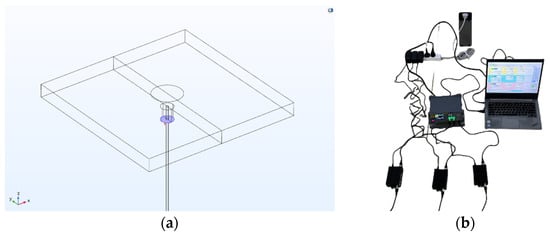
Figure 19.
Antenna lumped port (a); three channel signal generator (with power amplifier), with independent control of output amplitude and phase for each channel, used as a transmitter (b).
The coaxial cable used in feeding the monopole antenna plays a crucial role in its performance. The inner conductor of the coaxial cable is connected to the upper end of the antenna, while the outer conductor, or shield, is connected to the ground plane or platform. This arrangement facilitates efficient transmission of the radio frequency (RF) energy from the transmitter to the antenna. By connecting the grounding conductor to the platform, the monopole antenna achieves a stable reference point, which is essential for maintaining the antenna’s impedance and ensuring effective radiation.
In terms of its radiation characteristics, the monopole antenna exhibits a distinctive pattern. In the vertical plane, the quarter-wavelength monopole’s radiation pattern is similar to that of a half-wave dipole, forming a figure-eight shape that is symmetric about the vertical axis. This ensures that the energy is predominantly radiated horizontally, maximizing the coverage area. Unlike the dipole antenna, the monopole does not radiate energy into the ground, which reduces ground losses and enhances efficiency.
On the horizontal plane, the monopole antenna’s radiation is omnidirectional, meaning it radiates uniformly in all directions around the antenna. This characteristic is particularly advantageous in applications where 360-degree coverage is required, such as in airport runway monitoring or mobile communications. The omnidirectional radiation pattern ensures that the signal strength remains consistent regardless of the direction, providing reliable communication and monitoring capabilities.
Furthermore, the monopole antenna’s design and deployment can be optimized based on the specific application requirements. For instance, the height of the antenna and the dimensions of the ground plane can be adjusted to fine-tune the radiation pattern and impedance characteristics. This flexibility makes the monopole antenna a versatile solution for various remote sensing and communication applications.
The feeding of a monopole antenna using coaxial cables at the upper end, as shown in Figure 19a, and the connection of the grounding conductor to the platform, are critical for its effective operation. The quarter-wavelength monopole antenna’s radiation pattern in the vertical plane mirrors that of a half-wave dipole, without underground radiation, while its omnidirectional pattern on the horizontal plane ensures uniform signal distribution. These characteristics make the monopole antenna an efficient and versatile choice for applications requiring reliable and extensive coverage.
Figure 20 depicts the apparent resistivity measurements at a specific point in the FfR under the influence of airborne-dangled monopole-antenna remote-sensing radiation. To mitigate potential errors, measurements were iteratively conducted four times. The observed apparent resistivity values exhibit significant variability, spanning from 3 ohm·m to 350 ohm·m across frequencies ranging from 1 Hz to 10,000 Hz. This characterization underscores the diverse electromagnetic responses encountered within this frequency spectrum, crucial for understanding the environmental and geological implications of the remote sensing methodology employed.
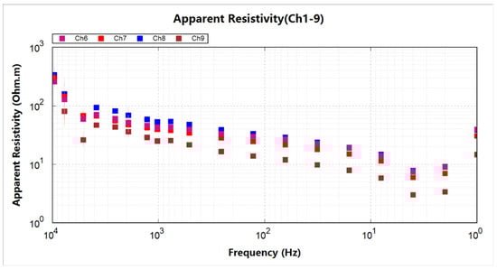
Figure 20.
The apparent resistivity at a measurement point in the FfR under the irradiation of airborne-dangled monopole-antenna remote-sensing radiation source.
In contrast, Figure 21 illustrates the apparent resistivity measurements at a specific point in the FfR, conducted under the influence of traditional grounded radiation sources. This experimental setup involves rigorous measurements conducted to ensure reliability, with data collected across multiple trials to mitigate potential sources of error. The observed apparent resistivity values demonstrate a notable range, varying from 4 ohm·m to 200 ohm·m, over a broad frequency spectrum spanning from 1 Hz to 10,000 Hz.
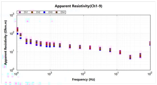
Figure 21.
The apparent resistivity at a measurement point in the FfR under the irradiation of traditional grounded radiation sources.
Upon analyzing data from both radiation sources, it is observed that their effects are relatively similar at low frequencies. However, significant differences emerge at high frequencies, primarily due to the diffraction and multipath interference characteristic of higher frequencies. Consequently, the efficacy of airborne-dangled monopole-antenna remote-sensing radiation sources in CSAMT remains within acceptable limits.
Furthermore, it is noteworthy that airborne-dangled monopole-antenna remote-sensing radiation sources exhibit superior maneuverability compared to their grounded counterparts. This enhanced maneuverability allows for the large-scale, extensive, and mobile monitoring of airport runways. Additionally, these airborne systems demonstrate significantly reduced energy consumption relative to traditional methods.
In summary, despite the challenges posed by high-frequency diffraction and multipath interference, the application of airborne-dangled monopole-antenna remote-sensing radiation sources in CSAMT is promising. Their ability to conduct efficient, large-area monitoring with lower energy requirements highlights their potential for broader, more economical deployment in practical scenarios.
7. Conclusions
Herein, we propose an innovative approach for airport runway monitoring through the deployment of an airborne-dangled monopole-antenna symmetric remote-sensing radiation source. This novel method leverages an airborne-dangled monopole-antenna symmetric remote-sensing radiation source in place of the traditional GHD systems. Our analysis, simulations, and experimental verifications have demonstrated that the energy required for the airborne-dangled monopole-antenna symmetric remote-sensing radiation source to generate an equivalent electric field amplitude in the frequency for FfR is merely one-third of that necessitated by conventional CSAMT methods. This substantial reduction in energy consumption not only enhances efficiency but also significantly curtails emissions, positioning the airborne-dangled symmetric remote-sensing radiation source as a superior alternative for airport runway monitoring applications.
In this study, we first delineate the fundamental principles and methodologies underpinning AD-CSAMT. Following this, we simulate the behavior of the dipole and its implementation within the CSAMT framework. Building on these foundational calculations and the analysis of AD-CSAMT principles, we develop several numerical models that provide analytical solutions for the application of AD-CSAMT in CSAMT contexts. Finally, we conduct a comprehensive comparison of the performance of AD-CSAMT against traditional methods from both simulation and experimental verification perspectives. The coherence between theoretical analysis, simulation results, and experimental data unequivocally confirms the correctness and efficacy of the proposed airborne-dangled symmetric remote-sensing radiation source for CSAMT applications.
To begin with, the principle and methodology of AD-CSAMT are elucidated, emphasizing the innovative aspects of the airborne-dangled monopole-antenna symmetric remote-sensing radiation source. The simulation of the dipole within the CSAMT application demonstrates its potential and advantages. Through rigorous calculations and thorough analysis, we establish several numerical models that provide analytical solutions, reinforcing the theoretical underpinnings of AD-CSAMT. These models are pivotal in understanding the interaction between the airborne-dangled symmetric remote-sensing radiation source and the runway monitoring environment.
Subsequently, we delve into the simulation results, where the advantages of AD-CSAMT over conventional CSAMT methods become apparent. The simulations reveal that AD-CSAMT not only achieves the desired electric field amplitude with significantly lower energy input but also offers improved spatial resolution and sensitivity, which are critical for precise runway monitoring. The experimental verification phase further substantiates these findings. Through controlled experiments, we observe that the performance metrics of AD-CSAMT align closely with the theoretical predictions and simulation outcomes. The consistency across these different validation methods underscores the robustness and reliability of the airborne-dangled symmetric remote-sensing radiation source.
In conclusion, the airborne-dangled monopole-antenna symmetric remote-sensing radiation source represents a significant advancement in CSAMT for airport runway monitoring. This innovative approach drastically reduces energy consumption while improving operational efficiency and environmental sustainability compared to conventional CSAMT methods. Our comprehensive analysis, detailed simulations, and rigorous experimental verifications affirm its efficacy. Comparing our approach with traditional methods used for monitoring foundation settlement, such as leveling instruments, total stations, and ground-penetrating radar, which rely on manual point measurements, reveals their limitations in automation, time-intensiveness, and potential disruption to airport operations. In contrast, the airborne-dangled symmetric remote-sensing radiation source enhances efficiency and reduces operational disruptions, making it a superior choice for runway monitoring applications.
Furthermore, our study advances upon existing technologies like synthetic aperture radar interferometry, which provides settlement data across large areas but struggles with subsurface resolution under pavements. In contrast, CSAMT, including our proposed airborne-dangled approach, excels in deep subsurface exploration despite technical challenges. Our simulations and experimental validations underscore the superiority of AD-CSAMT in achieving desired electric field amplitudes with significantly lower energy input, along with enhanced spatial resolution and sensitivity crucial for precise runway monitoring. These findings align closely with theoretical predictions and simulation outcomes, demonstrating the robustness and reliability of the airborne-dangled symmetric remote-sensing radiation source. In comparison with prior studies focusing on traditional CSAMT methods, which face limitations in energy efficiency and spatial resolution, our research highlights the transformative potential of the airborne-dangled monopole-antenna system. By offering superior performance metrics and operational advantages, our approach promises to advance geophysical monitoring practices and contribute to sustainable infrastructure management globally.
Looking ahead, expanding the scope of measurements beyond electric field parameters to include additional metrics such as magnetic field strength, SNR, and Cagniard apparent resistivity will be essential. Integrating these parameters will provide a more comprehensive understanding of subsurface characteristics, enhancing the accuracy and reliability of the monitoring system. By broadening the range of measured parameters, the airborne-dangled monopole-antenna system can offer even more robust insights, paving the way for sophisticated and effective remote sensing applications in airport runway monitoring and beyond.
Author Contributions
Conceptualization, Q.T.; methodology, Q.T. and H.F.; validation, H.F.; formal analysis, Q.T. and H.F.; data curation, J.C. and L.Z.; writing—original draft preparation, Q.T.; writing—review and editing, Q.T. and H.F.; visualization, Q.T.; supervision, Q.T.; project administration, L.Z.; funding acquisition, J.C. All authors have contributed significantly and have participated sufficiently to take responsibility for this research. All authors have read and agreed to the published version of the manuscript.
Funding
This work was supported by the Key Projects of the National Statistical Science (2023LZ001).
Data Availability Statement
Datas are contained within the article.
Conflicts of Interest
Authors Qianqian Tian and Haifeng Fan were employed by the companies Tianjin Multi-Intelligence Information Technology Co., Ltd. and Tianjin Yunsheng Intelligent Technology Co., Ltd., respectively. The remaining authors declare that the research was conducted in the absence of any commercial or financial relationships that could be construed as a potential conflict of interest. The Tianjin Multi-Intelligence Information Technology Co., Ltd. and Tianjin Yunsheng Intelligent Technology Co., Ltd. had no role in the design of the study; in the collection, analyses, or interpretation of data; in the writing of the manuscript, or in the decision to publish the results.
Abbreviations
The following abbreviations are used in this manuscript:
| CSAMT | Controlled-source audio-frequency magnetotellurics |
| AMT | Audio-frequency magnetotellurics |
| GHD | Grounded horizontal diploe |
| AD-CSAMT | Airborne-dangled CSAMT |
| FrR | Far-field region |
| SNR | Signal-to-noise ratio |
| RF | Radio frequency |
References
- Vyas, V.; Singh, A.P.; Srivastava, A. A decision making framework for condition evaluation of airfield pavements using non-destructive testing. In Airfield and Highway Pavements 2019: Innovation and Sustainability in Highway and Airfield Pavement Technology; American Society of Civil Engineers: Reston, VA, USA, 2019; pp. 343–353. [Google Scholar]
- Zhang, L.; Fan, Y.; Yan, R.; Shao, Y.; Wang, G.; Wu, J. Fine-Grained Tidal Flat Waterbody Extraction Method (FYOLOv3) for High-Resolution Remote Sensing Images. Remote Sens. 2021, 13, 2594. [Google Scholar] [CrossRef]
- Zhang, D. Talking about the Importance and Significance of General Aviation Airport Construction. Sci. Technol. Ind. Parks 2017, 15, 233. [Google Scholar]
- Ji, C.; Cheng, L.; Li, N.; Zeng, F.; Li, M. Validation of Global Airport Spatial Locations from Open Databases Using Deep Learning for Runway Detection. IEEE J. Sel. Top. Appl. Earth Obs. Remote Sens. 2020, 14, 1120–1131. [Google Scholar] [CrossRef]
- Tu, J.; Gao, F.; Sun, J.; Hussain, A.; Zhou, H. Airport Detection in SAR Images via Salient Line Segment Detector and Edge-Oriented Region Growing. IEEE J. Sel. Top. Appl. Earth Obs. Remote Sens. 2020, 14, 314–326. [Google Scholar] [CrossRef]
- Liu, N.; Cui, Z.; Cao, Z.; Pi, Y.; Dang, S. Airport Detection in Large-Scale SAR Images via Line Segment Grouping and Saliency Analysis. IEEE Trans. Geosci. Remote Sens. 2018, 15, 434–438. [Google Scholar] [CrossRef]
- Ai, S.; Yan, J.; Li, D. Airport Runway Detection Algorithm in Remote Sensing Images. Electron. Opt. Control. 2017, 24, 43–46. [Google Scholar]
- Marapareddy, R.; Pothuraju, A. Runway Detection Using Unsupervised Classification. In Proceedings of the 2017 IEEE 8th Annual Ubiquitous Computing, Electronics and Mobile Communication Conference (UEMCON), New York, NY, USA, 19–21 October 2017; IEEE: New York, NY, USA, 2017; pp. 278–281. [Google Scholar]
- Lu, X.; Lin, Z.; Han, P.; Zou, C. Fast Detection of Airport Runway Areas in PolSAR Images Using Adaptive Unsupervised Classification. Natl. Remote Sens. Bull. 2019, 23, 1186–1193. [Google Scholar] [CrossRef]
- Han, P.; Liu, Y.; Han, B.; Chen, Z. Airport Runway Area Detection in PolSAR Image Combined with Image Segmentation and Classification. J. Signal Process. 2021, 37, 2084–2096. [Google Scholar]
- Zhang, Z.; Zou, C.; Han, P.; Lu, X. A Runway Detection Method Based on Classification Using Optimized Polarimetric Features and HOG Features for PolSAR Images. IEEE Access 2020, 8, 49160–49168. [Google Scholar] [CrossRef]
- Liu, N.; Cao, Z.; Cui, Z.; Pi, Y.; Dang, S. Multi-Layer Abstraction Saliency for Airport Detection in SAR Images. IEEE Trans. Geosci. Remote Sens. 2019, 57, 9820–9831. [Google Scholar] [CrossRef]
- Zhao, D.; Li, J.; Shi, Z.; Jiang, Z.; Meng, C. Subjective Saliency Model Driven by Multi-Cues Stimulus for Airport Detection. IEEE Access 2019, 7, 32118–32127. [Google Scholar] [CrossRef]
- Zhang, Y.; Zhu, W.; Xing, Q. A Survey of SAR Image Segmentation Methods. J. Ordnance Equip. Eng. 2017, 38, 99–103. [Google Scholar]
- Han, P.; Liang, Y. Airport Runway Area Segmentation in PolSAR Image Based D-Unet Network. In Proceedings of the International Workshop on ATM/CNS, Tokyo, Japan, 25–27 October 2022; Electronic Navigation Research Institute: Tokyo, Japan, 2022; pp. 127–136. [Google Scholar]
- Tan, S.; Chen, L.; Pan, Z.; Xing, J.; Li, Z.; Yuan, Z. Geospatial Contextual Attention Mechanism for Automatic and Fast Airport Detection in SAR Imagery. IEEE Access 2020, 8, 173627–173640. [Google Scholar] [CrossRef]
- Chen, Y.; Dai, Y.; Liu, Y. Design and Implementation of Airport Runway Robot Based on Artificial Intelligence. In Proceedings of the 2021 IEEE 5th Advanced Information Technology, Electronic and Automation Control Conference (IAEAC), Chongqing, China, 12–14 March 2021; pp. 2636–2640. [Google Scholar]
- D’Amico, F.; Gagliardi, V.; Ciampoli, L.B.; Tosti, F. Integration of InSAR and GPR techniques for monitoring transition areas in railway bridges. NDT E Int. 2020, 115, 102291. [Google Scholar] [CrossRef]
- Iftimie, N.; Savin, A.; Steigmann, R.; Dobrescu, G.S. Underground Pipeline Identification into a Non-Destructive Case Study Based on Ground-Penetrating Radar Imaging. Remote Sens. 2021, 13, 3494. [Google Scholar] [CrossRef]
- Kaur, P.; Dana, K.J.; Romero, F.A.; Gucunski, N. Automated GPR rebar analysis for robotic bridge deck evaluation. IEEE Trans. Cybern. 2015, 46, 2265–2276. [Google Scholar] [CrossRef]
- Peng, M.; Wang, D.; Liu, L.; Shi, Z.; Shen, J.; Ma, F. Recent Advances in the GPR Detection of Grouting Defects behind Shield Tunnel Segments. Remote Sens. 2021, 13, 4596. [Google Scholar] [CrossRef]
- Liu, B.; Ren, Y.; Liu, H.; Xu, H.; Wang, Z.; Cohn, A.G.; Jiang, P. GPRInvNet: Deep Learning-Based Ground-Penetrating Radar Data Inversion for Tunnel Linings. IEEE Trans. Geosci. Remote Sens. 2021, 59, 8305–8325. [Google Scholar] [CrossRef]
- Qiu, Z.; Zhao, Z.; Chen, S.; Zeng, J.; Huang, Y.; Xiang, B. Application of an Improved YOLOv5 Algorithm in Real-Time Detection of Foreign Objects by Ground Penetrating Radar. Remote Sens. 2022, 14, 1895. [Google Scholar] [CrossRef]
- Lei, W.; Luo, J.; Hou, F.; Xu, L.; Wang, R.; Jiang, X. Underground cylindrical objects detection and diameter identification in GPR B-scans via the CNN-LSTM framework. Electronics 2020, 9, 1804. [Google Scholar] [CrossRef]
- Jaufer, R.M.; Ihamouten, A.; Goyat, Y.; Todkar, S.S.; Guilbert, D.; Assaf, A.; Dérobert, X. A Preliminary Numerical Study to Compare the Physical Method and Machine Learning Methods Applied to GPR Data for Underground Utility Network Characterization. Remote Sens. 2022, 14, 1047. [Google Scholar] [CrossRef]
- Li, P.; Huaici, Z. Monocular 3D Detection with Geometric Constraint Embedding and Semi-supervised Training. IEEE Robot. Autom. Lett. 2021, 6, 5565–5572. [Google Scholar] [CrossRef]
- Ling, J.; Qian, R.; Shang, K.; Guo, L.; Zhao, Y.; Liu, D. Research on the Dynamic Monitoring Technology of Road Subgrades with Time-Lapse Full-Coverage 3D Ground Penetrating Radar (GPR). Remote Sens. 2022, 14, 1593. [Google Scholar] [CrossRef]
- Kim, N.; Kim, S.; An, Y.K.; Lee, J.J. Triplanar imaging of 3-D GPR data for deep-learning-based underground object detection. IEEE J. Sel. Top. Appl. Earth Obs. Remote Sens. 2019, 12, 4446–4456. [Google Scholar] [CrossRef]
- Kang, M.S.; Kim, N.; An, Y.K.; Lee, J.J. Deep learning-based autonomous underground cavity detection using 3D GPR. Struct. Health Monit. 2020, 19, 173–185. [Google Scholar] [CrossRef]
- Li, H.; Chou, C.; Fan, L.; Li, B.; Wang, D.; Song, D. Toward automatic subsurface pipeline mapping by fusing a ground-penetrating radar and a camera. IEEE Trans. Autom. Sci. Eng. 2019, 17, 722–734. [Google Scholar] [CrossRef]
- Li, H.; Li, N.; Wu, R.; Wang, H.; Gui, Z.; Song, D. GPR-RCNN: An Algorithm of Subsurface Defect Detection for Airport Runway based on GPR. IEEE Robot. Autom. Lett. 2021, 6, 3001–3008. [Google Scholar] [CrossRef]
- Kim, N.; Kim, S.; An, Y.K.; Lee, J.J. A novel 3D GPR image arrangement for deep learning-based underground object classification. Int. J. Pavement Eng. 2021, 22, 740–751. [Google Scholar] [CrossRef]
- Chou, C.; Li, H.; Song, D. Encoder-Camera-Ground Penetrating Radar Sensor Fusion: Bimodal Calibration and Subsurface Mapping. IEEE Trans. Robot. 2020, 37, 67–81. [Google Scholar] [CrossRef]
- Giannopoulos, A. Modelling ground penetrating radar by GprMax. Constr. Build. Mater. 2005, 19, 755–762. [Google Scholar] [CrossRef]
- Cao, Q.; Al-Qadi, I.L. Effect of Moisture Content on Calculated Dielectric Properties of Asphalt Concrete Pavements from Ground-Penetrating Radar Measurements. Remote Sens. 2021, 14, 34. [Google Scholar] [CrossRef]
- Chen, M.S.; Yan, S. Research on the analysis for the copy effect of the field area, recording rule, shadow and field source in CSAMT exploration. Chin. J. Geophys. 2005, 48, 951–958. (In Chinese) [Google Scholar] [CrossRef]
- Tang, J.T.; Ge, W.N. Shadow and additional effect of the field source in 3D CSAMT. Comput. Tech. Geophys. Geochem. Explor. 2012, 34, 19–26. [Google Scholar]
- Shlykov, A.A.; Saraev, A.K. Wave effects in the field of a high frequency horizontal electric dipole. Izv. Phys. Solid Earth 2014, 50, 249–262. [Google Scholar] [CrossRef]
- Lei, D.; Wu, X.P.; Di, Q.Y.; Wang, G.; Lv, X.G.; Wang, R.; Yang, J.; Yue, M.X. Modeling and analysis of CSAMT field source effect and its characteristics. J. Geophys. Eng. 2016, 13, 49–58. [Google Scholar]
- Wang, X.X.; Di, Q.Y.; Xu, C. Characteristics of Multiple Dipole Sources and Tensor Measurement in CSAMT. J. Geophys. 2014, 57, 651–661. [Google Scholar]
- Fan, H.; Zhang, Y.; Wang, X. A novel phased-array transmitting source in controlled-source audio-frequency magnetotellurics. J. Geophys. Eng. 2022, 19, 595–614. [Google Scholar] [CrossRef]
- Mo, J. Analysis of Path Loss in Shortwave Ground Wave Propagation. Commun. World Second. Half Mon. 2016, 6, 3. [Google Scholar]
- Everaerts, J. The Use of Unmanned Aerial Vehicles (UAVs) for Remote Sensing and Mapping. Int. Arch. Photogramm. Remote Sens. Spat. Inf. Sci. 2008, 37, 1187–1192. [Google Scholar]
- Krellmann, Y.; Triltzsch, G. Hera-G—A new helicopter GPR based on gated stepped frequency technology. In Proceedings of the 14th International Conference on Ground Penetrating Radar (GPR 2012), Shanghai, China, 4–8 June 2012; pp. 156–159. [Google Scholar]
- Blindow, N.; Salat, C.; Casassa, G. Airborne GPR sounding of deep temperate glaciers—Examples from the Northern Patagonian Icefield. In Proceedings of the 14th International Conference on Ground Penetrating Radar (GPR 2012), Shanghai, China, 4–8 June 2012; pp. 670–675. [Google Scholar]
- Rutishauser, A.; Maurer, H.; Bauder, A. Helicopter-borne ground-penetrating radar investigations on temperate alpine glaciers: A comparison of different systems and their abilities for bedrock mapping. Geophysics 2016, 81, WA119–WA129. [Google Scholar] [CrossRef]
- Gusmeroli, A.; Wolken, G.J.; Arendt, A.A. Helicopter-borne radar imaging of snow cover on and aroundglaciers in Alaska. Ann. Glaciol. 2014, 55, 78–88. [Google Scholar] [CrossRef]
- Merz, K.; Green, A.G.; Buchli, T.; Springman, S.M.; Maurer, H. A new 3-D thin-skinned rock glacier model based on helicopter GPR results from the Swiss Alps. Geophys. Res. Lett. 2015, 42, 4464–4472. [Google Scholar] [CrossRef]
- Blindow, N.; Salat, C.; Gundelach, V.; Buschmann, U.; Kahnt, W. Performance and calibration of the helicopter GPR system BGR-P30. In Proceedings of the 6th International Workshop on Advanced Ground Penetrating Radar (IWAGPR 2011), Aachen, Germany, 22–24 June 2011. [Google Scholar]
- Arcone, S.A. Airborne-radar stratigraphy and electrical structure of temperate firn: Bagley Ice Field, Alaska, USA. J. Glaciol. 2002, 48, 317–334. [Google Scholar] [CrossRef][Green Version]
- Lambot, S.; Weihermüller, L.; Huisman, J.A.; Vereecken, H.; Vanclooster, M.; Slob, E.C. Analysis of air-launched ground-penetrating radar techniques to measure the soil surface water content. Water Resour. Res. 2006, 42, 11403. [Google Scholar] [CrossRef]
- Jadoon, K.Z.; Weihermüller, L.; McCabe, M.F.; Moghadas, D.; Vereecken, H.; Lambot, S. Temporal monitoring of the soil freeze-thaw cycles over a snow-covered surface by using airlaunched ground-penetrating radar. Remote Sens. 2015, 7, 12041–12056. [Google Scholar] [CrossRef]
- Fasano, G.; Renga, A.; Vetrella, A.R.; Ludeno, G.; Catapano, I.; Soldovieri, F. Proof of concept of micro-UAV-based radar imaging. In Proceedings of the International Conference on Unmanned Aircraft Systems (ICUAS), Miami, FL, USA, 13–16 June 2017; pp. 1316–1323. [Google Scholar]
- Garcia-Fernandez, M.; Alvarez-Lopez, Y.; Las Heras, F. Autonomous Airborne 3D SAR Imaging System for Subsurface Sensing: UWB-GPR on Board a UAV for Landmine and IED Detection. Remote Sens. 2019, 11, 2357. [Google Scholar] [CrossRef]
- Yao, H.; Qin, R.; Chen, X. Unmanned Aerial Vehicle for Remote Sensing Applications—A Review. Remote Sens. 2019, 11, 1443. [Google Scholar] [CrossRef]
- Wu, K.; Rodriguez, G.A.; Zajc, M.; Jacquemin, E.; Clément, M.; De Coster, A.; Lambot, S. A new drone-borne GPR for soil moisture mapping. Remote Sens. Environ. 2019, 235, 111456. [Google Scholar] [CrossRef]
Disclaimer/Publisher’s Note: The statements, opinions and data contained in all publications are solely those of the individual author(s) and contributor(s) and not of MDPI and/or the editor(s). MDPI and/or the editor(s) disclaim responsibility for any injury to people or property resulting from any ideas, methods, instructions or products referred to in the content. |
© 2024 by the authors. Licensee MDPI, Basel, Switzerland. This article is an open access article distributed under the terms and conditions of the Creative Commons Attribution (CC BY) license (https://creativecommons.org/licenses/by/4.0/).