Article

Transfer Learning-Based Steering Angle Prediction and Control with Fuzzy Signatures-Enhanced Fuzzy Systems for Autonomous Vehicles

by
Ahmet Mehmet Karadeniz
1,*,
Áron Ballagi
2 and
László T. Kóczy
3
1
Doctoral School of Multidisciplinary Engineering Sciences, Széchenyi István University, 9026 Györ, Hungary
2
Department of Automation and Mechatronics, Széchenyi István University, 9026 Györ, Hungary
3
Department of Informatics, Széchenyi István University, 9026 Györ, Hungary
*
Author to whom correspondence should be addressed.
Symmetry 2024, 16(9), 1180; https://doi.org/10.3390/sym16091180
Submission received: 2 August 2024 / Revised: 4 September 2024 / Accepted: 6 September 2024 / Published: 9 September 2024

Abstract

:
This research introduces an innovative approach for End-to-End steering angle prediction and its control in electric power steering (EPS) systems. The methodology integrates transfer learning-based computer vision techniques for prediction and control with fuzzy signatures-enhanced fuzzy systems. Fuzzy signatures are unique multidimensional data structures that represent data symbolically. This enhancement enables the fuzzy systems to effectively manage the inherent imprecision and uncertainty in various driving scenarios. The ultimate goal of this work is to assess the efficiency and performance of this combined approach by highlighting the pivotal role of steering angle prediction and control in the field of autonomous driving systems. Specifically, within EPS systems, the control of the motor directly influences the vehicle’s path and maneuverability. A significant breakthrough of this study is the successful application of transfer learning-based computer vision techniques to extract respective visual data without the need for large datasets. This represents an advancement in reducing the extensive data collection and computational load typically required. The findings of this research reveal the potential of this approach within EPS systems, with an MSE score of 0.0386 against 0.0476, by outperforming the existing NVIDIA model. This result provides a 22.63% better Mean Squared Error (MSE) score than NVIDIA’s model. The proposed model also showed better performance compared with all other three references found in the literature. Furthermore, we identify potential areas for refinement, such as decreasing model loss and simplifying the complex decision model of fuzzy systems, which can represent the symmetry and asymmetry of human decision-making systems. This study, therefore, contributes significantly to the ongoing evolution of autonomous driving systems.

1. Introduction

In recent years, the integration of computer vision techniques and fuzzy systems has shown promising results in improving steering angle prediction and control for autonomous systems. In particular, with the development of increasing mobility concepts, the intelligence of devices in mobility environments shall be improved [1]. Hence, smart systems such as autonomous vehicles and intelligent transportation systems are starting to play more vital roles in human lives [2]. In this article, we detail a simulation-oriented exploration into the utilization of computer vision and fuzzy systems for the prediction and control of steering angles in electric power steering (EPS) systems within a simulated context. The purpose is to analyze the effectiveness and performance of this amalgamated method [3].
The prediction of the steering angle plays a vital role in autonomous driving systems, particularly those employing EPS systems where motor control is essential for the vehicle’s trajectory and maneuvering skills. Computer vision techniques are crucial in retrieving visual data, including as lane markers, road borders, and nearby objects, which directly affect motor control in EPS systems. By analyzing the gathered visual data, we can accurately predict the steering angles that are important for safe and efficient maneuvering [4,5].
Fuzzy systems are a powerful tool for dealing with complex and uncertain entities, such as EPS. Specifically, fuzzy controllers use a combination of linguistic rules and fuzzy sets to navigate the inherent uncertainty and ambiguity found in real-world driving conditions [6,7]. When we integrate steering angle prediction, which is based on computer vision and controlling fuzzy systems, we enable autonomous vehicles with EPS systems to adapt to a wide range of road conditions. This integration also allows these vehicles to make precise decisions about motor control, leading to improved maneuvering [8].
An essential aspect to consider in the application of fuzzy systems for solving complex problems is the concept of symmetry and asymmetry. In this context, they do not refer to a geometric or mathematical property but rather to a metaphorical balance in the problem-solving process. This balance involves various dimensions, including the complexity of the problem, the resources required to solve it, and the accuracy or quality of the solution [9]. Fuzzy systems play a pivotal role in achieving this symmetry. Their ability to handle uncertainty and complexity allows for the approximation of the behavior of complex systems, providing solutions that are ‘good enough’ for practical purposes. This is particularly valuable in situations where exact solutions are not feasible due to the intractability of the problem [10].
Moreover, the transparency, ease of tuning, and flexibility of fuzzy systems contribute to this balance. These properties enable fuzzy systems to adapt to a wide range of functions and applications, thereby helping to balance the trade-off between solution accuracy and resource requirements. In this way, fuzzy systems contribute to symmetry in the problem-solving process, helping to achieve an optimal or ‘good enough’ solution that satisfies the expectations of the problem-setter while respecting the available resources. In summary, the concept of symmetry and asymmetry serves as a useful metaphor for understanding the role of fuzzy systems in solving complex problems. By helping to strike a balance between problem complexity, resource requirements, and solution accuracy, fuzzy systems enable the attainment of practical solutions to complex problems, thereby demonstrating the power and potential of fuzzy systems approaches [9].
In this study, we assess the effectiveness of steering angle prediction based on computer vision against a validation dataset. We also examine the control provided by fuzzy systems in a simulation environment. This simulated environment acts as a controlled platform to evaluate the suggested control method’s efficacy. By experimenting in this environment, we can explore the accuracy, robustness, and adaptability of EPS systems under various conditions.
Conducting this type of study is not without its challenges. These include the accurate modeling of the computer vision system, the development and fine-tuning of the fuzzy rule base and membership functions, and the validation of our findings against datasets.
This study offers valuable insights that enhance our understanding of how fuzzy systems can be used for steering motor control in EPS systems and how transfer learning-based computer vision can predict steering angles. The findings will shed light on the system’s operations, its limitations, and possible areas where it can be improved.
In conclusion, this paper delves into the joint use of transfer learning-based computer vision for predicting steering angles and fuzzy systems for EPS system control. The goal of the research is to evaluate the efficiency and performance of this combined method. This is performed by conducting experiments with a validation dataset for steering angle prediction and control within a MATLAB/Simulink simulation environment. The results will improve the understanding and knowledge of steering angle prediction using computer vision and motor control in EPS systems based on fuzzy systems enhanced with fuzzy signatures.

2. Related Works

In [11], the researchers reviewed steering angle prediction techniques and found out that conventional approaches for steering angle prediction usually consist of two phases, which are perception and control. This includes activities such as lane detection, trajectory planning, and control execution. In these conventional approaches, object detection is frequently considered a crucial method to enable autonomous driving. After detecting an item, the self-driving car may understand its environment and use the information it has learned to predict steering angles. But these approaches frequently require predetermined features and show poor resiliency. They have also investigated steering angle prediction techniques and have seen two main approaches. The first approach is using computer vision techniques leveraged by image processing. In this approach, images from the vehicle environment should be first captured through a camera. Then, these images are preprocessed to extract the necessary features. After preprocessing, these images are utilized for road detection and tracking algorithms, which analyze the drivable road region to derive parameters like steering angle, enabling the autonomous vehicle to maneuver within the lane boundaries. The second approach is through neural networks (NNs), which estimate the angle using input frames without additional road region extraction. This estimation can be performed with the derived parameters used by the controller to maintain the vehicle’s road position. And these neural networks are trained on datasets obtained from human driving demonstrations.
Furthermore, in order to facilitate vehicle maneuvering, the researchers in [12] proposed the End-to-End (E2E) model for steering angle prediction which learns directly from raw input data. It eliminates the need for intermediate variable computation. And this model demonstrates robustness and eliminates the need for manual feature definition. However, none of the evaluation metrics of the given study are mentioned, since the aim of the study was to demonstrate that the entire task of steering angle prediction can be achieved through CNNs without any additional feature extraction, such as detecting lane markings, trajectory planning, and control.
Deep neural networks are frequently used in the field of autonomous driving because they have demonstrated their effectiveness in addressing issues related to nonlinear mapping. Combining deep learning with the E2E model offers a proper method for figuring out how to drive in challenging environments. In [13], the researchers investigated two deep neural network models for steering angle prediction and compared them with NVIDIA’s [12] proposed model. One of them is the ResNet50 transfer learning model, and the other one is the 3D LSTM model. Based on their results, the ResNet50 transfer learning model provided the best result compared with NVIDIA’s model and the 3D LSTM model. The 3D LSTM provided the worst results among them. Moreover, they also indicated that the 3D LSTM model was limited because of the computational capacity, and it can be further developed with increased computational resources. In another study [14], the authors explored the use of an Artificial Neural Network (ANN) for predicting steering angles in autonomous vehicles. The proposed algorithm utilizes lane line coordinates for this prediction. The performance of the algorithm was tested on two different benchmarks (Udacity and Comma.ai) and then was compared with other relevant methods. It demonstrated superior accuracy and robustness compared with other ANN-based methods. However, they noted that the overall accuracy of the system is dependent on the efficiency of the lane detection algorithm.
This study presents a unified approach that merges Convolutional Neural Networks (CNNs) for predicting the steering angles by leveraging the transfer learning method and fuzzy systems for controlling. The CNN layer extracts spatial data from the input images and the predicted steering angle value is then fed into the fuzzy systems’ control algorithm. The VGG16-based Convolutional Neural Network model, which is a pretrained model on an existing dataset, is utilized to extract spatial features through transfer learning. The model’s evaluation was conducted on a public dataset, and it exhibits precise steering angle prediction across diverse environments. Furthermore, a control methodology based on fuzzy systems is developed that takes the output of the steering angle prediction model as input and provides a controlled steering angle for better maneuvering of autonomous vehicles.

3. Methodology

3.1. Convolutional Neural Networks

One of the neural network architectures is the “Convolutional Neural Network” architecture, which is effective in computer vision tasks and is used in detail in the modeling of this study. A CNN is the basic architectural structure of the deep learning concept. The first CNN architecture was created by Yann Le Cun in 1988 [15]. CNNs are deep neural networks designed to take images as inputs and are used effectively in computer vision, such as processing data that come as multiple arrayed 2D images or 3D videos. A CNN consists of single or several convolutional layers and single or multiple fully connected layers, like a standard multilayer neural network. These layers are the Input Layer, Convolution Layer, Flattening Layer, Pooling Layer, Fully Connected Layer, DropOut Layer, and Output Layer. The architectural structure chosen in the development of the study is CNN [16,17].

3.2. Transfer Learning

Transfer learning is a technical method in machine learning that realigns Convolutional Neural Networks (CNNs) initially trained for one task, to serve as a foundation for a model designed for a different task [18]. It enables the utilization of pre-existing, high-quality models that have been trained on extensive datasets. The primary benefit of transfer learning is its ability to apply the knowledge acquired from solving a similar problem, rather than initiating the learning process from zero. As a result, transfer learning capitalizes on prior learning, eliminating the need to start a new learning process from scratch [19]. This method has been employed in various classification problems, yielding satisfactory outcomes in terms of both training duration and accuracy. Transfer learning is typically implemented through the use of pretrained models. These are models that have been previously trained to address a problem similar to the one we aim to solve, using a comprehensive benchmark dataset [20,21]. In this study, the VGG16 model is used for the transfer learning task, and its architecture is provided in Figure 1.

3.3. Fuzzy Systems Control

Fuzzy theory, first introduced by Lotfi A. Zadeh in the mid-1960s, is now commonly incorporated into many industrial products [22]. These products utilize fuzzy controllers to automate operations based on linguistic rules to achieve desired outputs or responses. Fuzzy logic controllers are generally nonlinear and cannot be easily described by a simple mathematical equation. However, their widespread use in control applications is due to their simplicity, arising from their use of if–then rules [23].
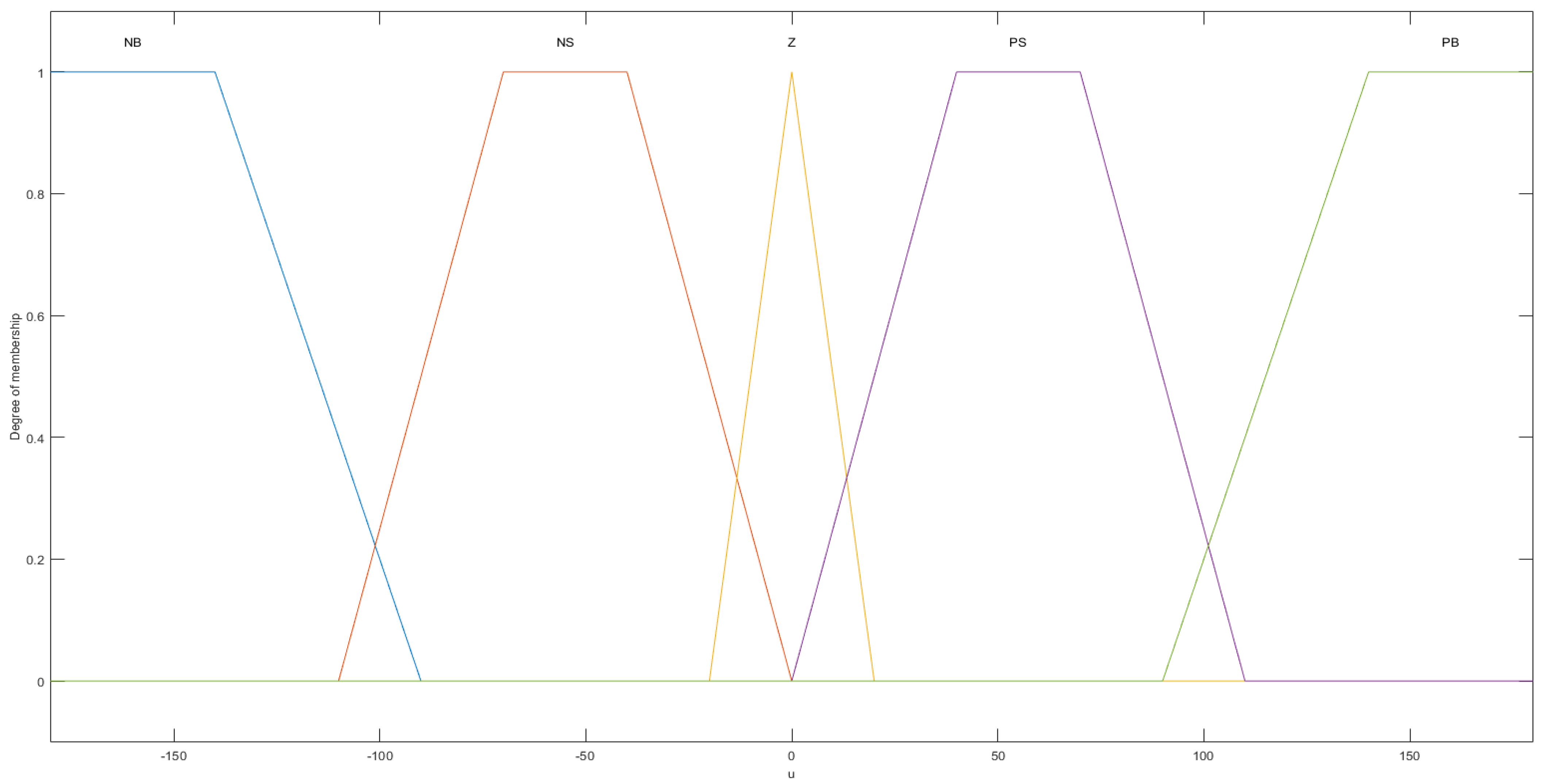
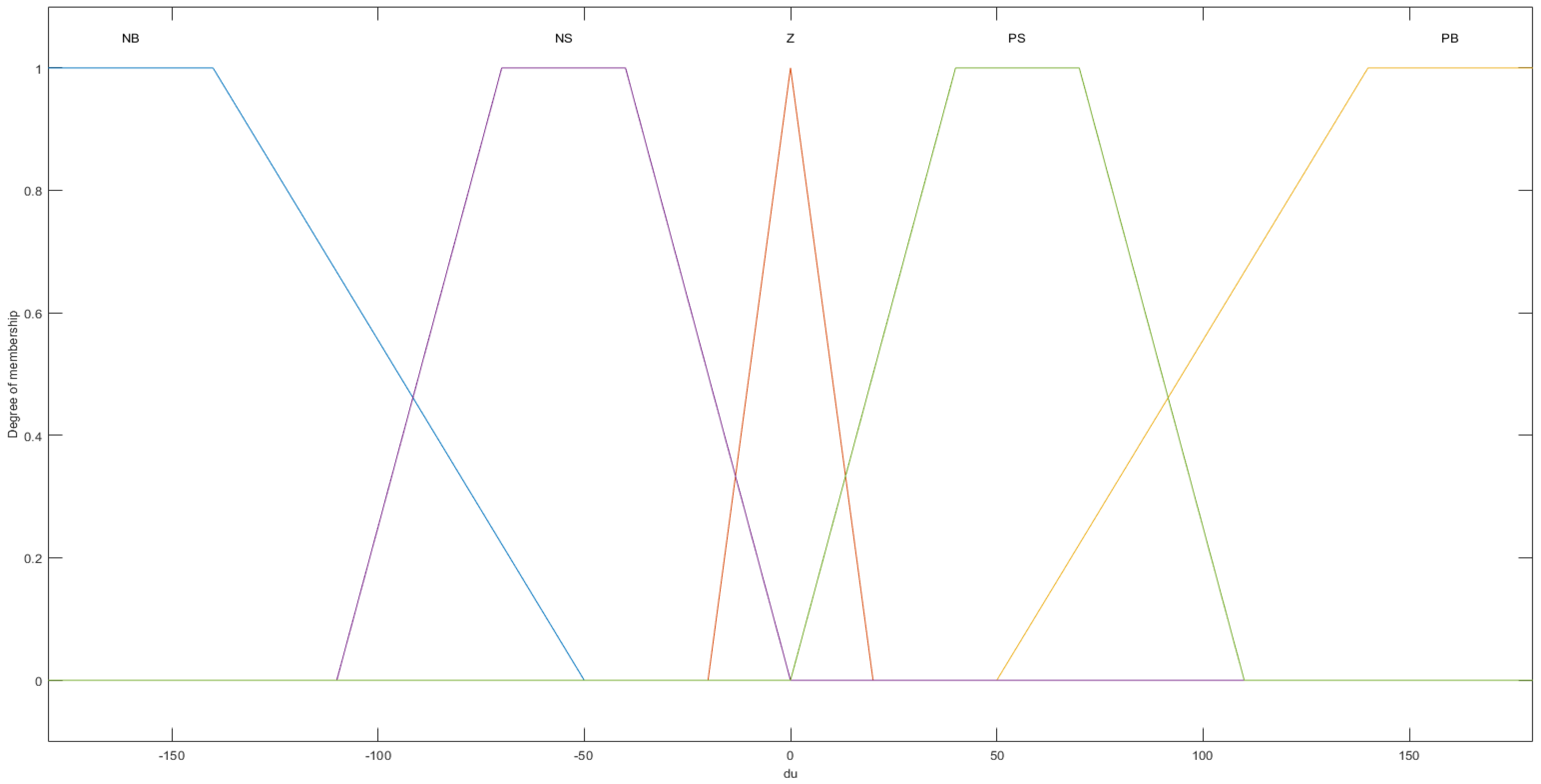
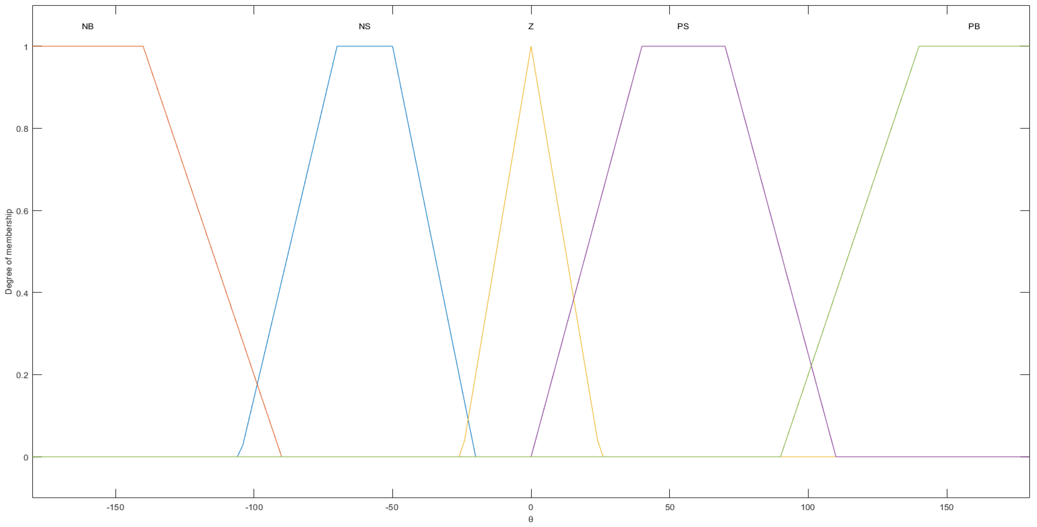
Unlike classical logic where distinctions are sharply defined, fuzzy logic allows for degrees of truth, meaning values can range between 0 and 1, not just the extremes. Common levels used in fuzzy logic controllers include NB (negative large), NS (negative small), Z (zero), PS (positive small), and PB (positive large). These levels can be transferred to the Matlab/Simulink environment using the Fuzzy Logic Toolbox. This toolbox also allows for the definition of the system’s membership functions using a fuzzy inference system created by experts, and the determination of the values of the membership functions [24]. The fuzzy logic controller model developed for this system requires careful identification of the membership functions. This includes determining the type, number of inputs and outputs, and fuzzification factors of the membership functions. In this study, generally, the trapezoidal membership function was chosen, with the exception of the Z membership function, which was selected as the triangular membership function to ensure high sensitivity and precise error reduction to zero. In general, the range of the membership functions can be defined by the user or researcher based on the specific needs of their study. It totally depends on the designers’ preferences. However, it needs to reflect the specific characteristics of the data being used. A key aspect of this process is the rule tables, which illustrate the relationship between input and output when using the fuzzy logic controller for control [25].

3.4. Fuzzy Signatures

Fuzzy signatures are referred to as a framework of the symbolic data representation. According to their definition, fuzzy signatures are a unique type of multidimensional data structure in which certain dimensions are connected to one another by forming a subset of variables that together determine a high-level feature [26]. The definitions of fuzzy signatures and fuzzy signature trees are underpinned by the subsequent recursive definition of the set S ( n ) . Let R denote the set of real numbers. The set S ( n ) is recursively defined as indicated in (1).
S ( n ) = i = 1 n S i ,
where S i = R , i = 1 , n (i.e., i { 1 , 2 , , n } ), or  S i = S ( m ) , m 1 , and ∏ is the Cartesian product.
Let X be a nonempty set. The collection of fuzzy signatures is defined as the function A : X S ( n ) , and the fuzzy signature of the element x X is A ( x ) given in a vector form, as in (2).
A ( x ) = a i a i + 1 , 1 a i + 1 , 2 a i + 2 , 1 a i + 2 , 2 , 1 a i + 2 , 2 , 2
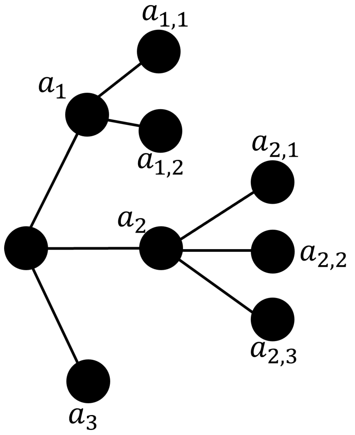
The element values a 1 , a 2 , , a n , a i , 1 , a i , 2 , , a i , m , , a j , k , l , that are present in the fuzzy signatures, as defined in (2), are named as the fuzzy signatures values [27]. The vector form of an exemplary fuzzy signature is given in (3), and the corresponding fuzzy signature tree is shown in Figure 2.
A ( x ) = a 1 , 1 a 1 , 2 a 2 , 1 a 2 , 2 a 2 , 3 a 3
Here, [ a 1 , 1 a 1 , 2 ] form a subgroup that corresponds to a higher level compound variable of a 1 . And  [ a 2 , 1 a 2 , 2 a 2 , 3 ] can be combined together to form a 2 . Then, eventually, the structure of the exemplary fuzzy signature can become A ( x ) = [ a 1 a 2 a 3 ] T . The connection between the higher and lower levels of the fuzzy signatures can be determined by a set of fuzzy aggregations assigned to the intermediate nodes of the tree graph (including the root). The parent fuzzy signature’s results at each level are calculated from their branches by appropriately aggregating their child fuzzy signature. Suppose @ 1 is the aggregation associating a 1 , 1 and a 1 , 2 used to derive a 1 , so a 1 = ( a 1 , 1 ) @ 1 ( a 1 , 2 ) . As shown in Figure 2, the aggregations for the entire fuzzy signature structure in the example would be @ 1 , @ 2 , and @ 0 . These aggregations, @ 1 , @ 2 , and @ 0 , may or may not be identical. The simplest case for each of them could be the min operation, which is a well-known t-norm. Furthermore, if the rule base of the fuzzy system has been clearly defined, it can facilitate the aggregation operation. This operation is essential for combining multiple input values to produce a single output value within the system.
Each fuzzy signature holds information pertinent to the specific data point A ( x ) ; as we go higher in the fuzzy signature structure, less information is retained. In some operations, it is necessary to condense and aggregate information obtained from another source (due to missing detail variables or local omissions). This situation arises when interpolation within a fuzzy signature rule base is performed and the fuzzy signatures surrounding an observation do not have exactly the same structure. In this case, the largest common subtree must be identified and all the fuzzy signatures must be reduced to that level to allow interpolation between the corresponding branches or roots in some instances [28].
A numerical example of the given exemplary fuzzy signature can be considered in (4). And let us assume that min aggregation is used at each level.
A ( x ) = 0.4 0.5 0.3 0.7 0.6 0.9
The highest level of the fuzzy signature structure can be obtained as given in (5), after performing the min aggregation operation on the lower levels:
A ( x ) = > 0.4 0.3 0.7 0.6 0.9 = > 0.4 0.3 0.9 = > 0.3

3.5. Data Preprocessing

The dataset used in this study includes around 20,000 images and their corresponding steering angle values. It is publicly available on Kaggle, as shown in [29]. Working with steering angles is a challenging task, since most of the angle values in the dataset are 0 or very close to zero. These types of data are called “biased data”, and they may result in weaknesses in any machine learning model. Besides this, it is also important to prepare data in a way that they fit to neural network’s input architecture, such as the size of the image, dimension, etc. Therefore, before feeding the CNN model, data preprocessing is needed to eliminate data from the “biased” state to the “unbiased” state, as well as reorganizing them to fit into CNN’s input [30,31].

3.6. Data Augmentation

In the referenced study [13], the researchers involved in the study found data augmentation to be beneficial alongside the original NVIDIA team. Identifying the types of augmentation that are effective for the available computational power and time could aid in training our new models. The method of the NVIDIA model is depicted in Figure 3. The model’s input was configured with dimensions of 120 × 320 × 3 and a batch size of 32. The NVIDIA paper [12] does not provide explicit details on how the loss function was optimized.
In this experiment, the Adam optimizer was employed with a learning rate set at 0.001. The bias towards turns present in the dataset was mitigated by randomly flipping the input images. The upper part of the image was cropped to eliminate the sky, which is not a relevant factor in predicting steering angles.
The steering angle prediction model proposed in this study can be represented by the following equation:
P = M ( W , V )
In this equation, P denotes the model’s output. M signifies the learned mapping from raw image sequences to the steering angle via the neural network model. W represents the trained weight parameter, while V corresponds to the input image sequences.
The loss function plays a crucial role in evaluating the model’s performance. In this work, we designed a loss function that uses the discrepancy between the predicted steering angle and the actual value. During the training phase, this loss function is used to adjust the weights in VGG16 for optimizing the deep neural network [31].

3.7. Model Architecture

A pretrained model VGG16 model is used in this study, and its architecture can be seen in Figure 1. A base VGG16 is kept by removing its last four layers. The output of VGG16 was connected to convolution layers consisting of 24, 36, 48, and 64 units, respectively. Then, a flattening layer was added, and last, it was followed by fully connected layers consisting of 100, 50, 10, and 1 units. Each fully connected layer contains a dropout layer along with itself for a better generalization of the model by preventing overfitting. Our model’s architecture can be seen in Figure 4.

3.8. Algorithm

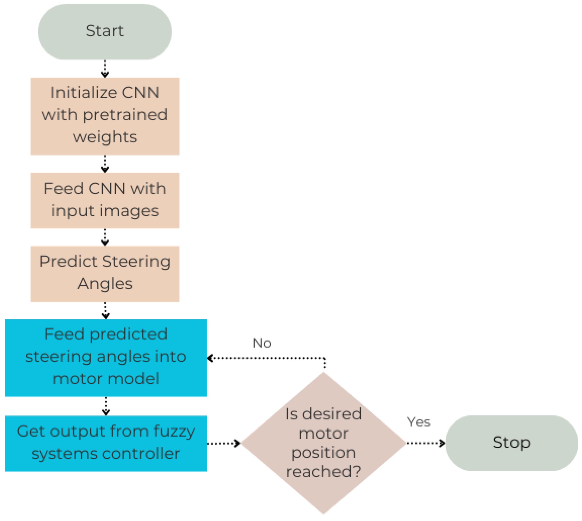
In our study, we employ a Convolutional Neural Network (CNN) model, denoted as M , and a fuzzy system controller, denoted as (G), to predict and control the steering angle in the context of electric power steering (EPS) systems. The flowchart of the algorithm for the complete system is given in Figure 5. Different colors are used to differentiate the parts corresponding to CNN-based prediction and fuzzy systems-based control.
The CNN model, initialized with a trained weight parameter W , processes the input image sequences, represented as V . The mathematical function M ( W , V ) captures this operation.
Upon processing the image sequences, the CNN model generates a prediction of the steering angles, which we denote as P .
Once the steering angles are predicted, they are fed into a motor model, which is governed by the fuzzy system controller. This operation is mathematically expressed as G( P ).
Subsequently, the fuzzy system controller generates an output, (O), based on the predicted steering angles, and this output is used to control the motor position. This relationship is captured by the function (O = G( P )).
Finally, the motor position, (C), is adjusted based on the output from the fuzzy system controller. This adjustment is mathematically represented as (C = C + O), and the final output of the algorithm is the controlled motor position, (C).
In essence, this algorithm represents the interplay between a CNN model and a fuzzy system controller in the prediction and control of steering angles within EPS systems. The mathematical formulas encapsulate the functions of the CNN model and the fuzzy system controller, as well as the steering angle and motor position adjustments. The algorithm followed in this study is presented in Algorithm 1.
Algorithm 1 Steering Angle Prediction and Control
Require: Input image sequences, V
Ensure: Controlled motor position, C
  1:
Initialize the CNN model, M , with trained weight parameter, W , and the fuzzy system controller, G
  2:
Feed input image sequences, V , to the CNN model: M ( W , V )
  3:
Predict steering angles, P , based on images: P = M ( W , V )
  4:
Feed predicted steering angles, P , into motor model with fuzzy system controller: G ( P )
  5:
Fuzzy system controller provides output, O, and controls motor position based on this controller output: O = G ( P )
  6:
Adjust motor position, C, based on controller output: C = C + O
  7:
return Controlled motor position, C

4. Modeling and Simulation

The study referenced in [12] demonstrates that the proposed model performs well, but it requires a substantial training time of several days on a single GPU. Clearly, this extended training time does not align with practical needs. To address this, we utilized the concept of transfer learning in the VGG16 model to reduce the training time.
The overall system architecture of this study is demonstrated in Figure 6. In this study, first, image sequences are fed into the CNN model as an input of the system. Then, the CNN processes these image sequences and outputs the predicted steering angle corresponding to the given image input. Later on, this predicted steering angle is fed into the step motor control model, and controlled steering angle is obtained as output of the system.

4.1. CNN Model Building with Transfer Learning

Transfer learning is a technical method that leverages pre-existing models that have been trained on large datasets. The pretrained weight parameters from these models can be directly applied to the new dataset. This approach circumvents the need to train models from scratch, thereby saving time during the training phase. Several pretrained deep neural network models are readily available, including ResNet50, VGG16, and InceptionV3, all of which have been pretrained on ImageNet. VGG16 was chosen for this study because various studies have verified its effectiveness in spatial feature extraction. Moreover, response time and computational complexity are critical for a real-time steering angle prediction system and VGG16 has fewer layers than other mentioned models and operates faster. Hence, the proposed model is fundamentally based on VGG16 with transfer learning. VGG16 demonstrated impressive performance in identifying approximately 1000 distinct object types in ImageNet [20,21,31]. Model training is performed in 20 epochs, while the NVIDIA model is trained in 30 epochs. As an activation function, “elu” is used, and for model evaluation purposes, Mean Squared Error (MSE) and Mean Absolute Error (MAE) are utilized. The proposed model consists of 69,651 trainable parameters out of a total of 14,784,339 parameters, while NVIDIA’s model is composed of 252,219 parameters, all of which are trainable. In the proposed model, the number of trainable parameters is significantly less than NVIDIA’s model despite the larger total number.

4.2. Motor Model

In this study, a step motor model is used to simulate the steering system environment as an electric motor of the steering system. Hence, our concept is to take images as inputs and drive the step motor to reach the targeted steering angle values, which are obtained as outputs of the Convolutional Neural Network (CNN) model. In order to realize this concept, images were first fed into the CNN for predicting steering angles. Then, these predictions were given as inputs to the designed motor model with a fuzzy system controller in order to be able to drive the motor to reach the desired steering angle. Based on the obtained step motor model in [24] via Park transformations, modeling was performed in a Matlab/Simulink environment. The Park transformation is used to transform the stator currents of a motor from the stator ( a b c ) reference frame to the rotor ( d q ) reference frame [32]. After the transformation, step motor equations are shown in (7) and (8):
i d = i a cos ( θ ) + i b cos ( θ 2 π 3 ) + i c cos ( θ + 2 π 3 )
i q = i a sin ( θ ) i b sin ( θ 2 π 3 ) i c sin ( θ + 2 π 3 )
where i d and i q are the d-axis and q-axis stator currents in the rotor reference frame, i a , i b , and i c are the a, b, and c stator currents in the stator reference frame, and θ is the rotor angle. The modeled step motor block diagram with fuzzy system controllers can be seen in Figure 7. The parameters and parameter values are chosen from [24] for the simulation, and they are shown in Table 1.

4.3. Fuzzy Signatures-Enhanced Fuzzy System Controller

In the implementation of the fuzzy signatures-enhanced fuzzy system controller, the initial step involved defining membership functions for each of the input and output variables. These include “u” (representing error at a higher level) and “ Δ u ” (indicating the change in error at the higher level of the fuzzy signature), as well as “e” (representing error at a lower level), “ Δ e ” (indicating the change in error at the lower level), and the output variable (controller). The same membership functions are defined for both “u” and “e”, as well as for “ Δ u ” and “ Δ e ”. As a result, only the membership functions for the highest level variables, which are “u” and “ Δ u ”, are shown.
The operation of a fuzzy logic system fundamentally relies on the concept of membership functions. Fundamentally, these functions establish the mapping of each point in the input space to a membership value or degree of membership. This mapping process supports in the handling of fuzzy sets and the implementation of fuzzy logic operations, thus enabling the system to reason in a fuzzy manner which is close to human reasoning [33].
To facilitate the creation of these membership functions, we used the Fuzzy Logic Toolbox in Matlab/Simulink. This toolbox provides a variety of tools and functions specifically tailored to assist in the design, simulation, and analysis of systems based on fuzzy logic [34].
In this study, during the fuzzification process, the membership functions are scaled within the range [− 180 , 180 ] because, in our experience, the values fall in this range for controlling the motor’s position. It could also be possible to perform this by adding additional gains, but this approach was preferred due to its convenience. The membership functions that we developed for the input and output variables in our fuzzy system controller are depicted in Figure 8, Figure 9 and Figure 10. This representation offers a clear understanding of the membership degree for each variable, providing significant insights into the operational dynamics of our fuzzy controller.
Our research relies on rule tables that illustrate the relationship between input and output in the control mechanism of a fuzzy logic controller. Essentially, these rule tables serve as a bridge between the input and output variables, enabling the fuzzy logic controller to make decisions based on the membership degree of the input data. They comprise a thorough set of “if–then” rules, which are based on expert knowledge and experience. The specific rule table employed in our research is detailed in Table 2.
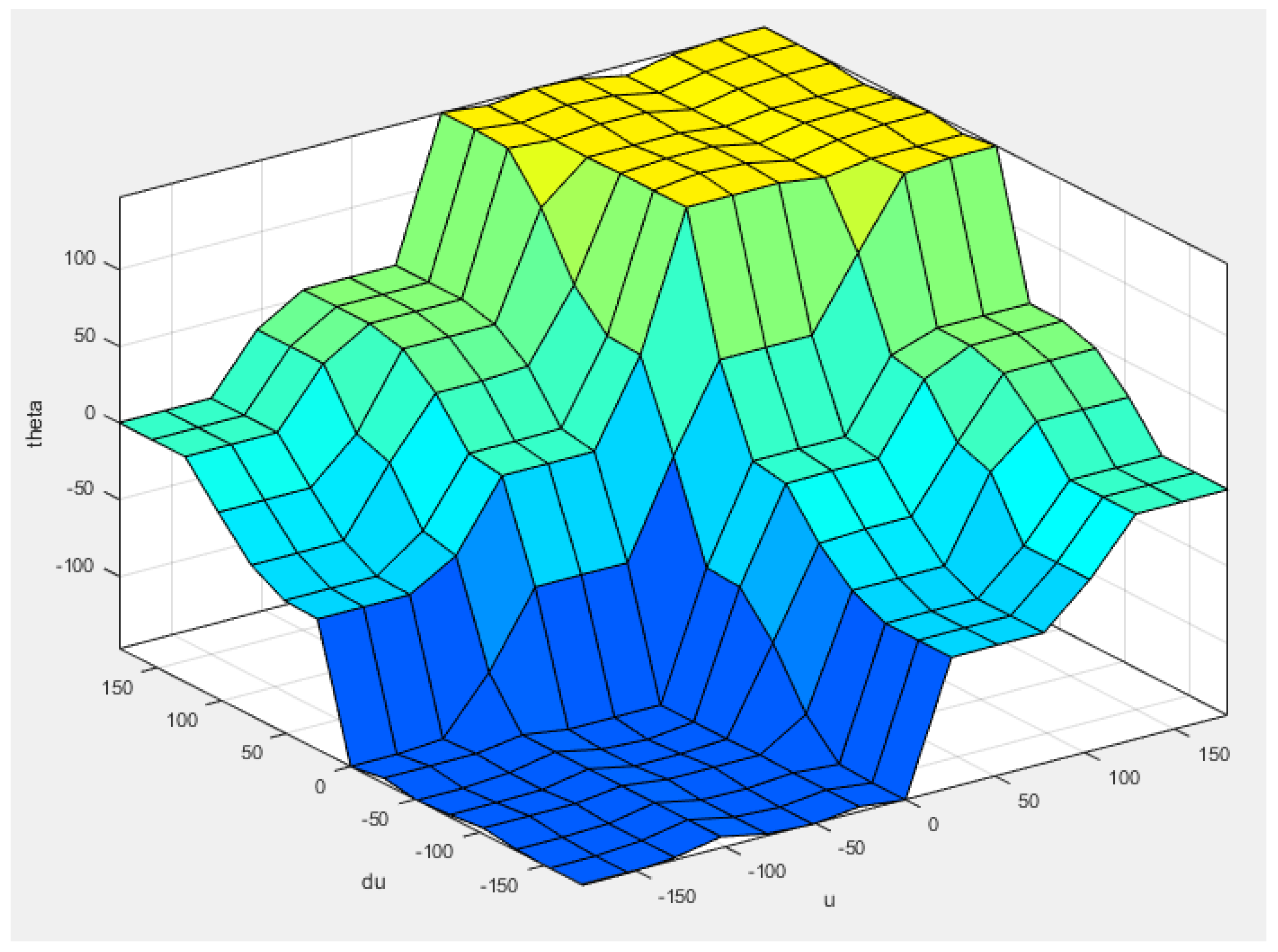
Figure 11 gives a graphical representation of the proposed fuzzy system’s effectiveness in generalizing the relationships between error, change in error, and motor position (angle) for motor control. This interdependence is illustrated through a fuzzy system rules surface. The rules surface suggests a correlation between the controlled motor position and both the error and change in error.
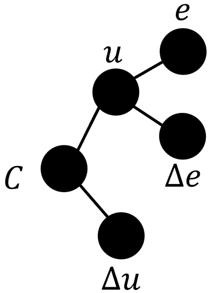
Additionally, our fuzzy system control method is enhanced with fuzzy signatures in order to obtain a simplified and agile model of our fuzzy system control method. As it can be seen in Figure 7, two fuzzy system control blocks are used in conjunction to form the fuzzy signature. The use of two blocks enhances the controlling ability of the proposed system. Hence, the system provides a more robust controlled output. The fuzzy signature model used in this study is given in (9), and the corresponding fuzzy signatures tree is shown in Figure 12.
C = e Δ e Δ u
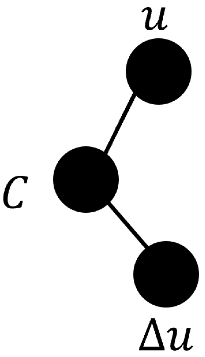
where “e” represents error, “ Δ e” represents change in error in lower level, “ Δ u” represents change in error in higher level of the fuzzy signature, and “C” is the main controller, which is the highest level. After aggregation of the subset “e” and “ Δ e”, the higher level “u” can be obtained. Thus, our fuzzy signature will be shaped as given in (10) and the fuzzy signature tree shown in Figure 13.
C = u Δ u
In our application, the elements of the fuzzy signature are aggregated using the rules of the fuzzy system, which are outlined in Table 2. The same rule base applies to both the relationship between “u” and “ Δ u ” and the relationship between “e” and “ Δ e ”.
The fuzzy signature employed in this study records the state of the motor position at each sampling time, creating a reference signal (C) for control decisions. Since the fuzzy signature processes the data in advance, the controller can operate with a straightforward fuzzy system rule base.
Let us consider Equation (11) as an example featuring linguistic values:
C = e Δ e Δ u = > P S Z N B
Once the aggregation process at the lower level is completed, following the rules outlined in Table 2, the output is determined to be “ P S ” if one input variable is “ P S ” and the other is “Z”. Subsequently, the higher level of the fuzzy signature will be as specified in Equation (12):
C = > P S N B
Therefore, the final structure of the fuzzy signature becomes as presented in Equation (13). This is because, according to Table 2, the output is determined to be “ N S ” when one input variable is “ P S ” and the other is “ N B ”:
C = > P S N B = > N S
Consequently, the control parameter “C” is designated as “ N S ”, which stands for ‘ N e g a t i v e S m a l l ’. The manipulation occurs according to this state, resulting in the motor position showing a small deviation from the desired position.

4.4. Experimental Steps

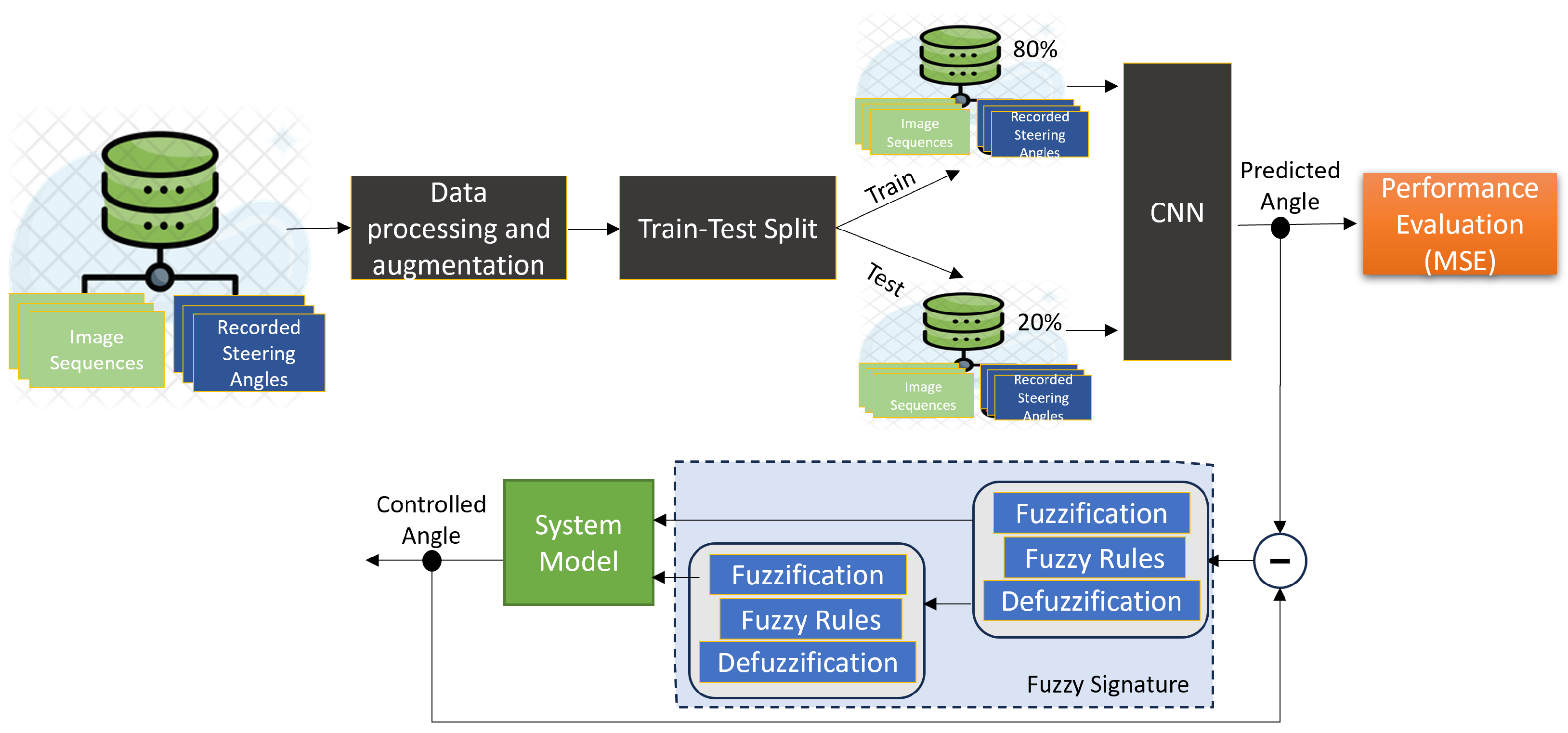
The process of experimentation in this study involves data processing and augmentation, train–test splits, model building and adjusting, performance evaluation, and designing the fuzzy signatures-enhanced fuzzy system controller. Firstly, data are processed, and augmentation steps consisting of horizontal flip, random brightness, and zooming are applied in order to increase the amount of samples in the dataset. Then, the pretrained model VGG16 is selected for transfer learning, and as a first step of the model building, the model input size is defined according to the image size. Then, the dataset is split into training and test datasets. The chosen pretrained model is used to extract the features from the training dataset. After feature extraction, the model is trained on the training dataset using the extracted features. The algorithm used for steering angle prediction and control, depicted in Figure 5, is applied next. The model’s performance is then validated on the test dataset with the MSE score serving as the evaluation metric. Finally, the trained model is used to predict steering angles.
In parallel, fuzzy systems control is also employed. For this reason, we first input and output membership functions, and then fuzzy inference rules are defined. Later on, the defuzzification method is selected; in this study, the centroid method is employed. In order to enhance the fuzzy systems control with fuzzy signatures, two fuzzy system controllers are used to represent higher and lower level branches. Finally, the predicted steering angle from the transfer learning model is given as an input to the controller, and the controlled steering angle results as output of the system. The overall experimental steps are illustrated in Figure 14.

5. Results

In order to assess the effectiveness and precision of various machine learning models in predicting and estimating steering angles, two metrics for performance measurement are employed in the relevant works. These include Mean Absolute Error (MAE) and Mean Square Error (MSE), which are utilized as evaluation metrics. The Mean Squared Error (MSE) is computed as the average of the squared differences between the actual steering angle values and their corresponding predicted values [20]. Mean Absolute Error (MAE) expresses the absolute error of the actual value. For the purpose of this study, we opted to use Mean Squared Error (MSE) as our primary metric and Mean Absolute Error (MAE) as a secondary metric to evaluate the models. Here, in (14), “n” represents the total number of samples (or steering angles, in this context), and “i” varies from 1 up to “n”.
MSE = 1 n i = 1 n ( Y i Y i ^ ) 2
Next, we consider the Mean Absolute Error (MAE), another important metric for evaluating our models. Unlike MSE, MAE does not square the residuals, which means it gives equal weight to all errors, regardless of their magnitude. This makes MAE more robust to outliers compared with MSE. The formula for MAE is given in (15):
MAE = 1 n i = 1 n Y i Y i ^
In the Formula (15), Y i represents the actual steering angle, and Y ^ i represents the predicted steering angle for the i-th sample. The absolute difference between the predicted and actual steering angle is calculated for each sample, and the results are averaged over all (n) samples to obtain the MAE.
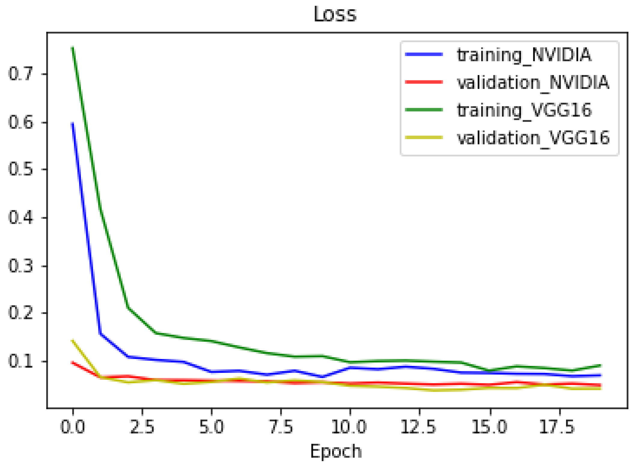
The training loss quantifies the model’s performance on the training dataset, while the validation loss provides an assessment of the model’s ability to handle data it has not been trained on, which gives an estimation of how the model will perform on unseen data. According to Figure 15, it can be seen that the NVIDIA model’s training loss is lower than the proposed model and therefore NVIDIA model learned the training data better. However, lower validation loss for the proposed model shows that it is better at making predictions on unseen data, which is ultimately what is cared about in deep learning models. Hence, it can be said that the proposed model’s generalization ability is much better than the NVIDIA model.
The proposed model achieved lower values of Mean Square Error (MSE) and Mean Absolute Error (MAE). Based on these metrics, the proposed transfer learning-based deep learning model’s performance surpasses the NVIDIA model’s performance for the steering angle prediction task. For comparison purposes, metrics are given in Table 3. As it can be seen in Table 3, the proposed model is 22.63% more beneficial for MSE value and 10.35% for MAE value.
Additionally, the proposed model in this study is compared with other relevant models mentioned in Section 2. The comparison with the NVIDIA model and other relevant studies is demonstrated in Table 4. Results are given in percentage of performance change compared with the NVIDIA model since, in the given studies, different evaluation metrics are used, such as RMSE and R 2 score. Based on the results, it can be seen that our model provides the best result against the NVIDIA model among all of the results. However, computational resources, including the amount and type of used accelerators (GPUs or TPUs), also should be investigated in order to have a proper comparative judgment. Unfortunately, this information is not provided in the mentioned studies; therefore, this kind of comparison is not available.
The maximum steering angle for vehicles is typically limited to 30° [35], although some special types of vehicles may have a limit of 45° [36]. In Table 5, we showcase a selection of results from our study that cover steering angle values within this range, as well as out of the safe range, to provide insight into how the system can behave under unsafe driving situations. Table 5 includes actual values with their corresponding predicted values derived from the Convolutional Neural Network (CNN) model, and the resulting output values generated by the designed fuzzy signatures-enhanced fuzzy system controller.

6. Conclusions

In conclusion, this study showed that the transfer learning-based Convolutional Neural Network (CNN) model and fuzzy signatures-enhanced fuzzy systems control mechanism proposed herein present a commendable performance. It shows that the developed model capably predicts steering angles across a wide range of driving conditions with better performance compared with the NVIDIA team’s model and concurrently with a fuzzy signatures-enhanced fuzzy system controller to guide the steering system to the desired position with notable accuracy.
One of the key achievements of this research is the successful attainment of the motor’s desired position, underscoring the potential applicability of this combined system in controlling the electric-powered steering system of autonomous vehicles. Enhancing the fuzzy system controller with fuzzy signatures provides a more simplified and compact way of the controller system.
It is important to note that the developed transfer learning-based Convolutional Neural Network model achieved a smaller Mean Square Error (MSE) value than that of the NVIDIA model, with a 22.63% lower loss. This shows that the proposed model surpassed NVIDIA’s model for this task with a lower loss value and better generalization ability. In addition to this, an important outcome of this study is the comparative performance of our proposed model against other relevant models discussed in Section 2. As demonstrated in Table 4, our model outperforms the other relevant models, albeit only slightly in the case of the ResNet50. Additionally, the other pretrained models also surpass the NVIDIA model. Considering this, it can show that in general, there is room for further refinement of deep learning models to improve their predictive accuracy with transfer learning using pretrained models. According to the proposed approach in this study, since the prediction output is the input for the controller system, the better the prediction means the more accurate input for the controller system; hence, the controller will have less deviation from the desired output overall.
Despite this, the findings of this study not only validate the proposed approach but also highlight promising areas for future research in autonomous vehicle technology. The next stages could involve enhancing the prediction model with Long-Short Term Memory (LSTM) or a Temporal Convolutional Network (TCN) to decrease the loss function. And control systems can be leveraged by optimization methods (such as Particle Swarm Optimization and Grey Wolf Optimization) for optimizing fuzzy membership functions and fuzzy rule bases in order to increase controllability and decrease complexity, thereby improving the predictive accuracy and control precision. Additionally, a real-world implementation of the proposed system could be performed first on a mobile robot and then on a prototype autonomous car. By doing this, system behavior under unexpected driving conditions can be explored and further development activities can be carried out. Hence, this ongoing work contributes to the broader goal of developing more sophisticated and reliable autonomous driving systems.

Author Contributions

Conceptualization, A.M.K.; methodology, A.M.K. and L.T.K.; project administration, L.T.K.; supervision, Á.B. and L.T.K.; writing—original draft, A.M.K.; writing—review and editing, A.M.K. and L.T.K. All authors have read and agreed to the published version of the manuscript.

Funding

The APC of this research was funded under Publications Support Program by the Strategic Ranking Committee and the University Library and Archives (SZEEKL) of Széchenyi István University.

Data Availability Statement

All data available regarding this study are shared in this paper, and the dataset used in this study is presented in [29].

Conflicts of Interest

The authors declare no conflicts of interest.

References

  1. Wolniak, R.; Stecuła, K. Artificial Intelligence in Smart Cities—Applications, Barriers, and Future Directions: A Review. Smart Cities 2024, 7, 1346–1389. [Google Scholar] [CrossRef]
  2. Bereczki, N.; Simon, V. Machine Learning Use-Cases in C-ITS Applications. Infocommunications J. 2023, XV, 26–43. [Google Scholar] [CrossRef]
  3. Shreyas, V.; Bharadwaj, S.N.; Srinidhi, S.; Ankith, K.U.; Rajendra, A.B. Self-driving cars: An overview of various autonomous driving systems. In Advances in Data and Information Sciences; Lecture Notes in Networks and Systems; Springer: Singapore, 2020; Volume 94, pp. 361–371. [Google Scholar] [CrossRef]
  4. Olivares-Mendez, M.A.; Sanchez-Lopez, J.L.; Jimenez, F.; Campoy, P.; Sajadi-Alamdari, S.A.; Voos, H. Vision-based steering control, speed assistance and localization for inner-cityvehicles. Sensors 2016, 16, 362. [Google Scholar] [CrossRef]
  5. Farkh, R.; Alhuwaimel, S.; Alzahrani, S.; Jaloud, K.A.; Quasim, M.T. Deep learning control for autonomous robot. Comput. Mater. Contin. 2022, 72, 2811–2824. [Google Scholar] [CrossRef]
  6. Mayne, A.J.; Klir, G.J.; Folger, T.A. Fuzzy Sets, Uncertainty, and Information. J. Oper. Res. Soc. 1990, 41, 884. [Google Scholar] [CrossRef]
  7. Ross, T. Fuzzy Logic with Engineering Applications, 3rd ed.; Wiley India Pvt. Ltd.: Bengaluru, India, 2011. [Google Scholar]
  8. Shukla, S.; Tiwari, M. Fuzzy Logic of Speed and Steering Control System for Three Dimensional Line Following of an Autonomous Vehicle. arXiv 2010, arXiv:1004.1675. [Google Scholar]
  9. Kóczy, L.T. Symmetry or Asymmetry? Complex Problems and Solutions by Computational Intelligence and Soft Computing. Symmetry 2022, 14, 1839. [Google Scholar] [CrossRef]
  10. Kóczy, L.; Zorat, A. Fuzzy systems and approximation. Fuzzy Sets Syst. 1997, 85, 203–222. [Google Scholar] [CrossRef]
  11. Saleem, H.; Riaz, F.; Mostarda, L.; Niazi, M.A.; Rafiq, A.; Saeed, S. Steering Angle Prediction Techniques for Autonomous Ground Vehicles: A Review. IEEE Access 2021, 9, 78567–78585. [Google Scholar] [CrossRef]
  12. Bojarski, M.; del Testa, D.W.; Dworakowski, D.; Firner, B.; Flepp, B.; Goyal, P.; Jackel, L.D.; Monfort, M.; Muller, U.; Zhang, J.; et al. End to End Learning for Self-Driving Cars. arXiv 2016, arXiv:1604.07316. [Google Scholar]
  13. Du, S.; Guo, H.; Simpson, A. Self-Driving Car Steering Angle Prediction Based on Image Recognition. arXiv 2019, arXiv:1912.05440. [Google Scholar]
  14. Faizi, F.S.; Alsulaifanie, A.K. Steering angle prediction via neural networks. Indones. J. Electr. Eng. Comput. Sci. 2023, 31, 392–399. [Google Scholar] [CrossRef]
  15. Le Cun, Y.; Jackel, L.; Boser, B.; Denker, J.; Graf, H.; Guyon, I.; Henderson, D.; Howard, R.; Hubbard, W. Handwritten digit recognition: Applications of neural network chips and automatic learning. IEEE Commun. Mag. 1989, 27, 41–46. [Google Scholar] [CrossRef]
  16. LeCun, Y.; Bengio, Y.; Hinton, G. Deep learning. Nature 2015, 521, 436–444. [Google Scholar] [CrossRef]
  17. Taherdoost, H. Deep Learning and Neural Networks: Decision-Making Implications. Symmetry 2023, 15, 1723. [Google Scholar] [CrossRef]
  18. Chen, J.; Chen, J.; Zhang, D.; Sun, Y.; Nanehkaran, Y. Using deep transfer learning for image-based plant disease identification. Comput. Electron. Agric. 2020, 173, 105393. [Google Scholar] [CrossRef]
  19. Iman, M.; Arabnia, H.R.; Rasheed, K. A Review of Deep Transfer Learning and Recent Advancements. Technologies 2023, 11, 40. [Google Scholar] [CrossRef]
  20. Sharma, S.; Jhaketiya, V.; Kaul, A.; Raza, A.A.; Ahmed, S.; Naseem, M. Automatic Prediction of Road Angles using Deep Learning-Based Transfer Learning Models. IOP Conf. Ser. Mater. Sci. Eng. 2021, 1099, 012060. [Google Scholar] [CrossRef]
  21. Muneeb ul Hassan. VGG16—Convolutional Network for Classification and Detection. 2018. Available online: https://neurohive.io/en/popular-networks/vgg16/ (accessed on 12 May 2024).
  22. Zadeh, L. Fuzzy sets. Inf. Control 1965, 8, 338–353. [Google Scholar] [CrossRef]
  23. Jantzen, J. Fuzzy Control. In Foundations of Fuzzy Control; John Wiley & Sons, Ltd.: Hoboken, NJ, USA, 2013; Chapter 3; pp. 55–84. [Google Scholar] [CrossRef]
  24. Karadeniz, A.M.; Alkayyali, M.; Péter Tamás, S. Modelling and Simulation of Stepper Motor For Position Control Using LabVIEW. Recent Innov. Mechatronics 2018, 5, 1–5. [Google Scholar] [CrossRef]
  25. Ahmet Mehmet, K.; Ammar, A.; Geza, H. Comparison between proportional, integral, derivative controller and fuzzy logic approaches on controlling quarter car suspension system. MATEC Web Conf. 2018, 184, 02018. [Google Scholar] [CrossRef]
  26. Pozna, C.; Minculete, N.; Precup, R.E.; Kóczy, L.T.; Ballagi, Á. Signatures: Definitions, operators and applications to fuzzy modelling. Fuzzy Sets Syst. 2012, 201, 86–104. [Google Scholar] [CrossRef]
  27. Kóczy, L.T.; Cornejo, M.E.; Medina, J. Algebraic structure of fuzzy signatures. Fuzzy Sets Syst. 2021, 418, 25–50. [Google Scholar] [CrossRef]
  28. Ballagi, Á.; Kóczy, L.T. Fuzzy signature based mobil robot motion control system. In Proceedings of the 2008 6th International Symposium on Applied Machine Intelligence and Informatics, Herlany, Slovakia, 21–22 January 2008; pp. 29–33. [Google Scholar]
  29. Moin, A. Udacity Self Driving Car—Behavioural Cloning. 2023. Available online: https://www.kaggle.com/code/shruti9821/self-driving-car-behavioural-cloning/input (accessed on 20 October 2023).
  30. Devnani, V.; Panjwani, C.; Kachhela, N.; Tewari, A.; Gwalani, N. Angle Detection of Steering in a Self-Driving Car. In Recent Trends in Materials; Springer: Singapore, 2022; Volume 18, pp. 453–462. [Google Scholar] [CrossRef]
  31. Jiang, Z.P.; Liu, Y.Y.; Shao, Z.E.; Huang, K.W. An improved VGG16 model for pneumonia image classification. Appl. Sci. 2021, 11, 11185. [Google Scholar] [CrossRef]
  32. Wang, C.; Cao, D. New Sensorless Speed Control of a Hybrid Stepper Motor Based on Fuzzy Sliding Mode Observer. Energies 2020, 13, 4939. [Google Scholar] [CrossRef]
  33. Godfrey, H. Fuzzy Logic with MATLAB; CreateSpace Independent Publishing Platform: North Charleston, SC, USA, 2016. [Google Scholar]
  34. Sivanandam, S.; Sumathi, S.; Deepa, S. Introduction to Fuzzy Logic Using MATLAB; Springer: Berlin/Heidelberg, Germany, 2006. [Google Scholar]
  35. Khristamto, M.; Praptijanto, A.; Kaleg, S. Measuring Geometric and Kinematic Properties to Design Steering Axis to Angle Turn of The Electric Golf Car. Energy Procedia 2015, 68, 463–470. [Google Scholar] [CrossRef]
  36. Anggono, A.D.; Sedyono, J.; Handaga, B. Geometric modeling and assembly analysis of 90 degree steering system. AIP Conf. Proc. 2018, 1977, 020063. [Google Scholar] [CrossRef]
Figure 1. VGG16 architecture.
Symmetry 16 01180 g001
Figure 2. Example corresponding fuzzy signature tree.
Symmetry 16 01180 g002
Figure 3. NVIDIA neural network training method.
Symmetry 16 01180 g003
Figure 4. Our model architecture with VGG16.
Symmetry 16 01180 g004
Figure 5. Algorithm flowchart of the complete system.
Symmetry 16 01180 g005
Figure 6. System architecture of the overall system.
Symmetry 16 01180 g006
Figure 7. Step motor Simulink model with fuzzy signatures-enhanced fuzzy system controller.
Symmetry 16 01180 g007
Figure 8. Membership function “u”.
Symmetry 16 01180 g008
Figure 9. Membership function “ Δ u ”.
Symmetry 16 01180 g009
Figure 10. Membership function “output” (as “ θ ”).
Symmetry 16 01180 g010
Figure 11. Rules surface of motor position (angle) for error and change in error.
Symmetry 16 01180 g011
Figure 12. Fuzzy signatures tree used in this study.
Symmetry 16 01180 g012
Figure 13. Fuzzy signature tree after aggregation.
Symmetry 16 01180 g013
Figure 14. Experimental steps flow chart.
Symmetry 16 01180 g014
Figure 15. Training and validation losses of the models.
Symmetry 16 01180 g015
Table 1. Parameters and their values used in the simulation.
Parameter (unit)Value
J (kg·m2)0.08
B (kg/s·m)3
R (ohm)6
L (mH)3
k3
p4
Table 2. Incorporating rules between the input variables u and Δ u .
Δ u/uNBNSZPSPB
NBNBNBNBNSZ
NSNBNBNSZPS
ZNBNSZPSPB
PSNSZPSPBPB
PBZPSPBPBPB
Table 3. Comparison of Model Validation Metrics.
ModelMean Squared Error (MSE)Mean Absolute Error (MAE)
NVIDIA0.04860.1622
Proposed Model0.03760.1454
Benefit22.63%10.35%
Table 4. Comparison with other Relevant Models relative to NVIDIA model.
ModelPerformance Change (%)
3D LSTM [13]−13.89
ResNet50 Transfer Learning [13]22.11
ANN [14]10.87
Proposed Model22.63
Table 5. Comparison of Actual, Predicted, and Output Values.
Actual ValuePredicted ValueOutput Value
5.04°6.15°6.01°
15.03°13.88°13.73°
29.75°28.15°28.71°
45.0°42.05°42.24°
54.0°50.80°50.62°
−15.13°−14.80°−14.50°
−20.27°−21.16°−19.89°
−27.0°−28.08°−28.27°
−45.0°−42.38°−42.53°
Disclaimer/Publisher’s Note: The statements, opinions and data contained in all publications are solely those of the individual author(s) and contributor(s) and not of MDPI and/or the editor(s). MDPI and/or the editor(s) disclaim responsibility for any injury to people or property resulting from any ideas, methods, instructions or products referred to in the content.