Abstract
The increasing demand for ultra-fast charging in electric vehicles (EVs) necessitates advancements in thermal management strategies to mitigate Joule heating, which arises due to electrical resistance in charging connectors and cable cores. This study presents a numerical analysis of immersion cooling performance for ultra-fast chargers under realistic charging conditions. The simulated results are validated by experiments with a maximum deviation of 5.5% at 600 A and 700 A currents. The novelty of this work lies in the consideration of a realistic charging cable length of 5 m, the evaluation of temperature characteristics in the charger connector, and the analysis of geometric symmetry in the charging cable and coolant configuration to ensure uniform heat distribution. Key operating conditions were systematically analyzed, including applied currents, ambient temperatures, coolant flow rates, cable core cross-sectional areas, and different types of coolants. Results indicate that increasing the applied current from 400 A to 800 A raised the connector temperature from 60.73 °C to 97.33 °C. As the ambient temperature increased from 20 °C to 50 °C, the connector temperature rose significantly from 42.71 °C to 74.99 °C, while the maximum cable core temperature increased from 65.26 °C to 100.61 °C. Increasing the cable core cross-sectional area from 20 mm2 to 30 mm2 reduced the connector temperature from 77.20 °C to 74.99 °C. Meanwhile, increasing the coolant flow rate from 2 LPM to 5 LPM had a negligible effect on the connector temperature. Among the three tested coolants, Novec 7500 exhibited the highest cooling efficiency, achieving the lowest contact temperature (74.76 °C) and the highest performance evaluation criteria (PEC) value of 3.8. This study provides valuable guidelines for enhancing symmetry-driven thermal management systems and demonstrates the potential of immersion cooling to improve efficiency, safety, and operational reliability in next-generation high-power EV chargers.
1. Introduction
The transport sector is one of the largest consumers of fossil fuels, negatively affecting air quality and increasing greenhouse gas (GHG) emissions [1]. In 2021, total emissions from all modes of transport reached 7.65 Gt CO2, accounting for 37% of global emissions, of which road transport contributed 77%. The transition from internal combustion engine (ICE) vehicles to electric vehicles (EVs) helps reduce emissions and improve environmental sustainability [2,3]. Lithium-ion batteries are the most widely used type in EVs due to their outstanding advantages, such as high energy density, high performance, long life, and fast charging capability [4,5]. These advantages help optimize the performance of EVs.
With the rapid development of the electric vehicle industry, the demand for ultra-fast charging systems is increasing. Fast charging methods, including quick, fast or ultra-fast charging can reach up to 120 kW. Recently, the extreme fast charging (XFC) technology has been introduced with a power of about 350 kW, allowing 80% of the battery capacity to be recharged in just 15 min or less, depending on the battery capacity of the vehicle [6,7]. This significantly enhances the convenience of using EVs, especially on long trips.
Although ultra-fast charging significantly improves charging time, it also poses a major challenge related to the heat generated at the contact points, especially the connector between the charger and the electric vehicle. Joule heating, which originates from the resistance at the connectors, is the main cause of heat generation, which degrades the power transfer efficiency and can affect the safety of the system. If not effectively controlled, this phenomenon can lead to overheating, shorten the life of the device, or even cause a fire hazard [8]. Therefore, research and development of efficient thermal management systems for ultra-fast charger connectors is an important factor in ensuring safety and improving the durability and operating performance of electric vehicle chargers under high-power current charging conditions.
Conventional air cooling is effective for slow charging systems but is insufficient to meet the heat dissipation requirements of fast charging systems [9]. For fast and ultra-fast chargers with large heat generation, advanced cooling methods such as liquid cooling are attracting attention and application research [10,11,12]. Current super-fast charging systems with large capacities have shifted from forced convection air cooling to liquid cooling systems with better heat transfer efficiency [8]. Liquid cooling systems are classified into indirect liquid cooling systems and direct liquid cooling systems [13]. Indirect liquid cooling systems use water or a water–glycol mixture as a coolant and absorb heat from the heat-generating components through intermediate heat transfer structures [14]. With the advantages of high specific heat and thermal conductivity, indirect liquid cooling systems provide superior heat transfer efficiency compared to air cooling systems. However, the indirect cooling system has the disadvantages of a complex structure, risk of coolant leakage, high thermal resistance and large pump energy consumption [15].
Recently, direct liquid cooling or immersion cooling has emerged as a promising cooling method for thermal management systems requiring high cooling performance [16]. Immersion cooling provides superior cooling efficiency. Its optimal cooling mechanism involves a coolant with high specific heat capacity and thermal conductivity in direct contact with the heat-generating surface. This enables rapid heat dissipation and maintains optimal operating temperatures for all components in systems that require effective thermal management [17]. Some coolants used in immersion cooling systems include dielectric fluid, hydrofluoroethers, hydrocarbons, esters, mineral oils and silicone oils [18]. With its superior cooling performance and high reliability using a non-conductive dielectric coolant, the immersion cooling method has proven to be effective in the thermal management of energy storage systems and high-power electronic devices [19,20,21,22]. Therefore, the immersion cooling method is effective and promises to provide excellent thermal management performance for the connector in the ultra-fast charger in this study.
Several recent studies have evaluated immersion cooling for electric vehicle chargers. Wu et al. analyzed the effect of the helical structure of the wire core on heat transfer in dimethyl silicone oil liquid-cooled cables, showing that the heat transfer performance improved within the immersion cooling medium and the wire core helix pitch decreased [8]. Devahdhanush et al. used the immersion cooling method with a two-phase cooling mode using HFE-7100 dielectric fluid, which maintains the temperature of the charging wire below 85 °C even when the current reached 2000 A [10]. Peng Sun et al. employed a liquid metal as the working fluid for fast charger cable cooling and leveraged the cable’s internal current to generate Lorentz forces via a magnetohydrodynamic (MHD) method. Consequently, they demonstrated that the fluid can be circulated solely by self-induced electromagnetic forces, eliminating the need for external pumping devices [23].
Most previous studies on immersion cooling for EV charger connectors have focused on short core wires without considering realistic charging station conditions, where core wires exceed 5 m in length. As the length of the core wire increases, electrical resistance rises, significantly affecting heat generation, cooling efficiency, and overall system performance. Additionally, during ultra-fast charging, the charger connector becomes a major heat source, directly impacting charging efficiency and system safety. However, few existing studies comprehensively analyze the thermal behavior and cooling performance of immersion cooling systems for charger connectors during ultra-fast charging processes. Furthermore, the significance of geometric symmetry in charging cable and coolant design and its influence on uniform heat distribution and fluid dynamics have been inadequately explored.
To address the above research gap, the current study examined the thermal behavior of a 5 m-long charging cable, providing a realistic assessment of immersion cooling under practical operating conditions. In addition, the study comprehensively evaluated the cooling performance of the charger connector with critical parameters such as cable core cross-sectional area, coolant type, connector temperature, cooling capacity, and pressure drop during ultra-fast charging with an immersion cooling system. Furthermore, this study uniquely analyzes the heat transfer characteristics of different coolants in an immersion cooling system to optimize cooling performance and enhance system safety. This study evaluates cooling efficiency and heat transfer in ultra-fast EV chargers, focusing on symmetry in heat transfer and fluid flow. Therefore, this study hypothesizes that implementing a symmetrical immersion cooling configuration along with the careful selection of coolant and operational conditions will result in improved thermal uniformity, reduced heat generation and enhanced overall performance of EV ultra-fast charging systems. These insights contribute to both cooling performance optimization and system safety, ensuring more effective and reliable thermal management in next-generation ultra-fast charging applications for EVs.
2. Materials and Methods
2.1. Description of Numerical Modeling
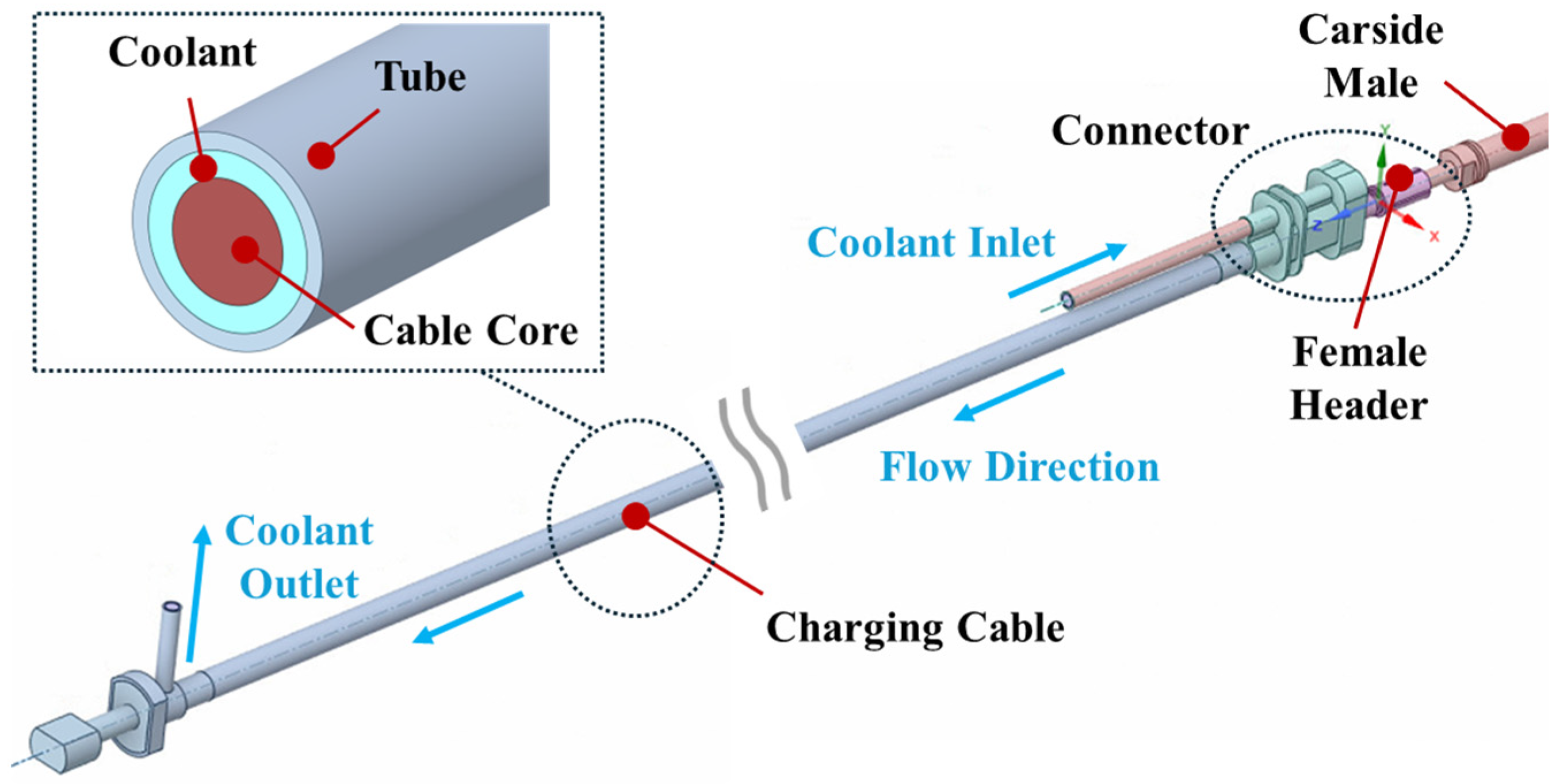
In this study, a 5.0 m-long charging cable was modeled based on a commercially available ultra-fast charging cable designed for EVs. The numerical model used in this study is illustrated in Figure 1. The charging cable consists of a conductive core, which serves as the main heat source, enclosed within a cylindrical tube. On the vehicle side, the charging cable is connected to a female header connector, which matches the corresponding male connector on the vehicle. To enhance thermal management, immersion cooling is employed, in which a non-conductive coolant fully surrounds the conductive core, filling the space between the core and the cylindrical tube. This method ensures efficient heat dissipation by allowing direct contact between the coolant and the heat-generating conductive core. The coolant circulation system is designed to optimize heat dissipation.
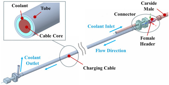
Figure 1.
Modeling of the charging cable with immersion cooling for ultra-fast charger.
Coolant is supplied through a dedicated inlet near the connector side and flows around the conductive core to absorb heat directly. By integrating immersion cooling with a symmetrical flow model, this design greatly improves the thermal performance of the charging cable, ensuring stable operation under high-power charging conditions. The specifications of the charging cable and connector used in the present analysis are shown in Table 1. The cable core cross-sectional areas of 20, 25, and 30 mm2 were selected to examine the influence of core size on resistive heating and to identify an optimal balance between electrical and thermal performance. The cable diameter was set to 12 mm for the cases with core areas of 20 and 25 mm2, while a diameter of 13 mm was applied for the case with a core area of 30 mm2. This adjustment was made to maintain a consistent hydraulic diameter and to avoid constrained flow paths, ensuring fair comparison of coolant behavior and pressure drop characteristics across different core sizes.

Table 1.
Specifications of charging cable and connector.
2.2. Governing Equation and Data Reduction
The heat generation in the charging cable is primarily due to Joule heating, , which can be expressed as the product of voltage and current . Since voltage is the product of current and resistance, Joule heating can be formulated as follows:
The resistance of the current is given by the following equation:
where is the resistivity, is the length of the cable core, and is the cross-sectional area. The resistance varies with the material’s temperature, and this change is determined by the temperature coefficient . If the resistance value is at a reference temperature, and the temperature difference between the reference and actual temperatures is , the change in resistance can be expressed as the product of and . Consequently, Joule heating is formulated as follows [24]:
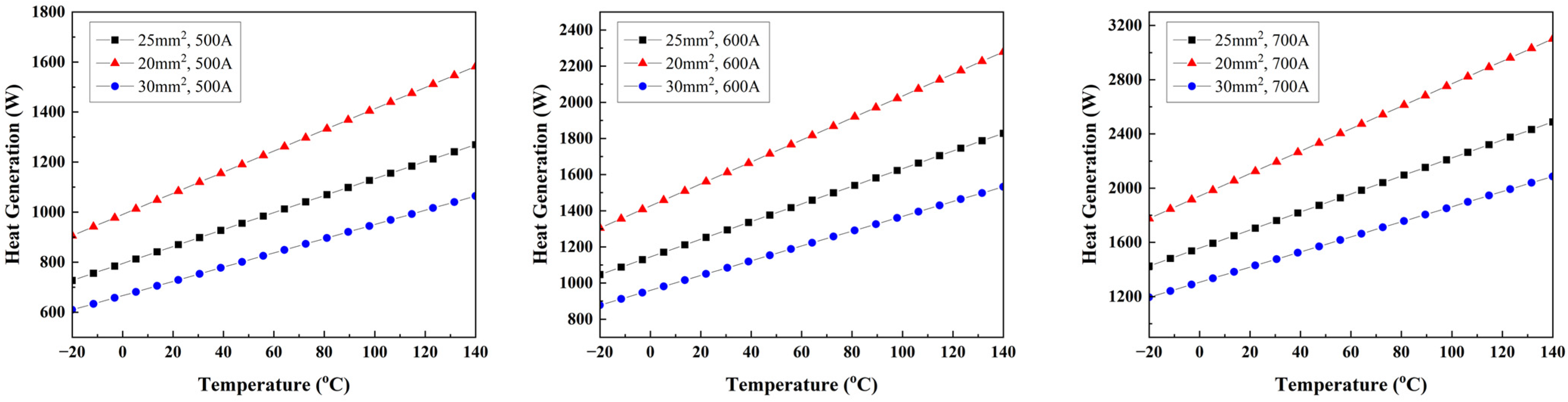
As shown in Equation (3), resistance increases as the temperature of the cable core rises, resulting in greater heat generation. Since resistance is inversely proportional to the cross-sectional area, the heat source in the charging cable and connector was divided into 10 parts according to the cross-sectional area to calculate the heat generation. The heat generation of the charging cable is shown in Figure 2, considering the cable core cross-sectional area, applied current, and temperature.
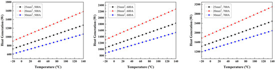
Figure 2.
Variation in heat generation of cable core by cross-sectional area and temperature.
The Biot number () of the cable core is calculated as follows [24]:
where is the convective heat transfer coefficient, k is the thermal conductivity of the cable core, and is the characteristic length. and represent the volume and surface area of the cable core, respectively. The Biot number of the cable core was found to be less than 0.1, indicating that the internal temperature difference can be neglected. Therefore, the internal temperature of the cable core was assumed to be uniform. The thermal contact conductance (TCC) between copper surfaces was set at 25,000 W/m2·K, and TCC was applied at male–female connections. This study used three types of coolants: Novec 7500 (Company: 3M Co., Ltd., Saint Paul, MN, USA), Pitherm 150B (Company: Pitherm Chemical Co., Ltd., Suwon-si, Republic of Korea) and ZIC ES 1 (Company: SK Enmove Co., Ltd., Seoul, Republic of Korea). The properties of these coolants are listed in Table 2 [25,26,27].
Table 2.
The properties of coolants used in the present study.
Computational Fluid Dynamics (CFD) simulations were conducted using ANSYS Fluent 2023 R2 to analyze the coolant flow characteristics. The coolant circulates through the annular space between the cable core and the outer tube, which can be approximated as an annular tube for modeling purposes. The Reynolds number was determined based on the hydraulic diameter and outlet velocity of the cable core. The analysis confirmed that the flow within the charging cable remains laminar, necessitating the use of a laminar flow model in the simulations for accurate thermal and fluid dynamic predictions as follows:
where is the fluid density, is the dynamic viscosity, is the kinematic viscosity, is the flow velocity, and is the hydraulic diameter of the annular tube. The heat transfer between the heat source and the coolant occurs through forced convection. In the steady state, the heat generation in the cable core equals the heat absorption of the coolant, which can be expressed as follows:
where is the overall heat transfer coefficient, is the convective heat transfer area, is the mass flow rate of the coolant, is the specific heat, and is the coolant temperature difference between the inlet and outlet. The Nusselt number (), a parameter, was used to evaluate the heat transfer performance of the coolant as follows:
The required pumping power of the coolant was evaluated using the friction factor as follows:
where is the pressure drop, is the pipe length, is the coolant density, and is the coolant velocity.
The performance evaluation criteria () were used to compare the overall effectiveness of different coolants by considering both heat transfer performance and energy consumption in the system as follows:
2.3. Mesh Independence Test
To ensure the reliability of the numerical simulations, a mesh independence study was performed by generating five different mesh configurations. The number of mesh elements and the corresponding simulation results for each case are presented in Figure 3. As the mesh was refined from Mesh 3 to Mesh 4, the observed differences in temperature and pressure drop were 1.86% and 0.67%, respectively. However, this refinement resulted in a significant increase in computational cost, with the simulation time increasing by more than 1.3 times. Given this trade-off between solution accuracy and computational efficiency, Mesh 3 was selected as the optimal configuration for further analysis, as it provided a balance between numerical accuracy and computational feasibility.
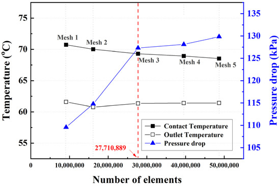
Figure 3.
Mesh independence test.
2.4. Numerical Model Verification
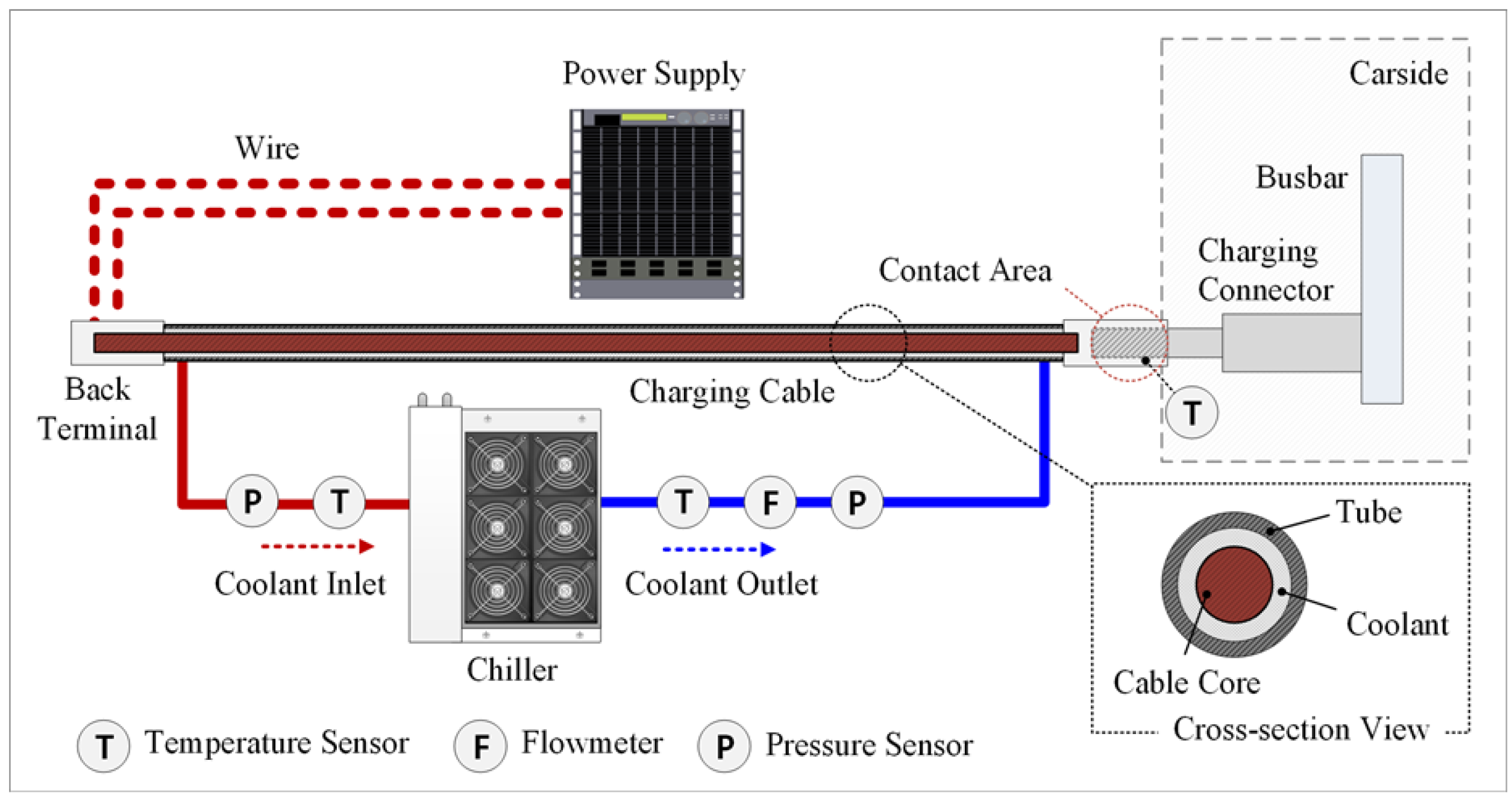
To validate the numerical analysis, experimental tests were conducted on a 5 m-long cable core under applied electrical current. The schematic diagram of the experimental setup of the charging cable with immersion cooling is presented in Figure 4. During the experiment, the current flowed from the back terminal at the charging station, through the cable core of the charging cable, and into the charging connector. As shown in Figure 5, the connector establishes a direct electrical connection to the electric vehicle. In this configuration, the cable core is linked to the female header, which subsequently interfaces with the male connector on the vehicle side. This experimental setup closely replicates the operating conditions of a high-power charging system, allowing validation of the numerical model through direct comparison with the measured data.
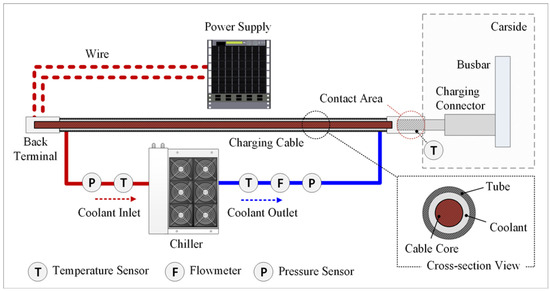
Figure 4.
Experimental schematic of a charging cable with immersion cooling.
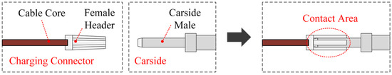
Figure 5.
Structure of charging connector and carside.
In this study, carside refers to the component of the electric vehicle that interfaces with the charger during the charging process. It consists of the male connector and the busbar, which facilitate the electrical connection. Joule heating occurs in all conductive components where current flows. However, the long and narrow cable core generates the highest heat generation due to its electrical resistance and extended length. The maximum volumetric heat generation is observed at the contact interface between the female connector of the charging cable and the male connector on the carside, where electrical contact resistance is highest. The experimental conditions for the study are detailed in Table 3.
Table 3.
Experimental specifications of charging cable with immersion cooling.
A current range of 600–700 A was chosen for the experiment as it represents realistic high-power charging conditions commonly used in ultra-fast EV charging systems. At these current levels, Joule heating is significant, allowing for a clear evaluation of the immersion cooling system’s effectiveness in dissipating heat. Additionally, this range ensures that the cooling system can handle high thermal loads, preventing overheating and maintaining system stability. To supply electrical currents of 600 A and 700 A, a DC power supply (EX10-1000, ODA Technologies, Incheon, Republic of Korea, 13 kW, 10 V, 1000 A, Accuracy: ±0.1%) was utilized [28]. To regulate the temperature of the coolant, a 4 kW air-cooled chiller was employed, ensuring effective heat dissipation during the experiment. Voltage and temperature measurements were conducted using a data acquisition unit (34970A, Keysight, Santa Rosa, CA, USA, Accuracy: ±1.5%) providing high-precision data collection for analysis [29]. Pitherm 150B was selected as the coolant with a flow rate from 3.2 to 3.3 LPM for the cooling system, facilitating efficient heat transfer and maintaining thermal stability throughout the experimental process.
The validation between the numerical and experimental results is shown in Figure 6. The validation between the simulation results and experimental measurements for the 5 m-long cable core under 600–700 A current demonstrated a maximum deviation of 0.8% in contact temperature and 5.5% in the coolant inlet–outlet temperature difference. Given that the maximum error remained within 6%, the numerical model was deemed to exhibit high reliability, thereby validating the accuracy and effectiveness of the computational analysis.
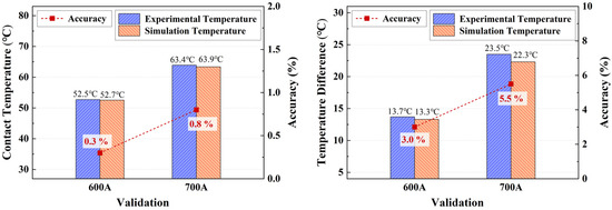
Figure 6.
Validation of numerical results with experimental data.
3. Results and Discussion
Effective thermal management is crucial for ensuring the safety, reliability, and efficiency of ultra-fast chargers for EVs. During ultra-fast charging, significant Joule heating occurs in the cable core and connector interface, necessitating an optimized cooling strategy to prevent overheating and maintain stable operation. The performance of the cooling system is influenced by various factors, including the applied current, ambient temperature, coolant flow rate, cable core cross-sectional area, and type of coolant used. This section presents a comprehensive numerical analysis of the cooling performance under different operating conditions. Key thermal and fluid parameters such as contact temperature, maximum cable core temperature, pressure drop, coolant inlet–outlet temperature difference, Nusselt number, friction factor, and performance evaluation criteria (PEC) are evaluated to assess the efficiency of heat dissipation and flow characteristics. The analysis conditions used in the analysis are summarized in Table 4.
Table 4.
Analysis conditions of ultra-fast charger cooling system.
The current conditions were set considering the commercialized 350 kW (1000 V, 350 A) standard and the specifications for ultra-fast charging above 400 kW, applying current levels from 400 A to 800 A. The ambient temperature was varied from 20 °C to 50 °C, taking into account normal room temperature as well as the thermally harsh conditions experienced during summer. The coolant flow rate was set between 2 and 5 LPM, based on the specifications of the chiller and cable core used in the experiments. The cable core cross-sectional area was set to 20, 25, and 30 mm2 to analyze the impact of different cable core sizes. A transient thermal-fluid simulation case was also conducted to examine system behavior over a realistic 10 min fast-charging period. Symmetry was considered in the geometric design of the charging cable to ensure uniform heat distribution and coolant flow. The results provide insights into the impact of each parameter on thermal behavior and cooling efficiency, offering guidance for optimizing the connector, charging cable design, and cooling system performance.
3.1. Effect of Different Applied Currents
This section analyzes the impact of different applied current values on the cooling performance of the connector and charging cable. Understanding this relationship is essential, as increasing current levels result in greater Joule heating, which can significantly influence the thermal management of the system. Ensuring efficient heat dissipation is crucial for maintaining safe operation, thermal stability, and prolonged durability of the charger, particularly in high-power charging applications. By evaluating the thermal and fluid dynamics under various current levels, the effectiveness of the cooling system can be assessed, providing insights into optimizing the connector and cable design for enhanced performance.
To assess the cooling performance, several key parameters were considered. The contact temperature at the connector interface was measured, as this is a critical factor affecting potential thermal stress and material degradation at electrical connection points. Additionally, the maximum temperature of the cable core was analyzed, as excessive temperatures could lead to performance deterioration and safety concerns. The pressure drop along the coolant flow path was evaluated to determine its impact on fluid dynamics and cooling efficiency. Lastly, the coolant inlet–outlet temperature difference was examined to assess the heat absorption capability of the coolant, providing an indicator of the overall cooling system’s effectiveness.
The numerical simulations were conducted under well-defined steady-state conditions to ensure accurate and realistic results. Applied currents including 400 A, 500 A, 600 A, 700 A, and 800 A were analyzed in this section. The coolant flow rate was set at 3 L per minute (LPM), with an ambient temperature of 50 °C. The coolant inlet temperature was also maintained at 50 °C, and Pitherm 150B was used as the coolant due to its superior heat transfer properties. Additionally, the cable core area was specified as 30 mm2 to reflect the actual operational setup of the charging system. These conditions were selected to replicate the expected real-world charging environment, allowing for meaningful comparisons between different current levels.
To evaluate the cooling performance, the analysis focused on identifying the maximum heat generation location in the cable core, determining the contact temperature at the connector interface, and examining the pressure drop and temperature variations in the coolant flow. Under steady-state conditions, the heat dissipation capacity of the coolant is assumed to be equal to the heat generation in the cable core, following the law of energy conservation. Therefore, the heat generation rate can be estimated based on the temperature increase of the coolant as it flows through the system. Figure 7 presents the simulation results obtained for different applied current values.
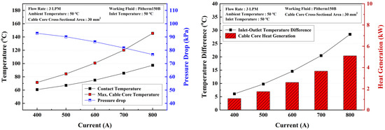
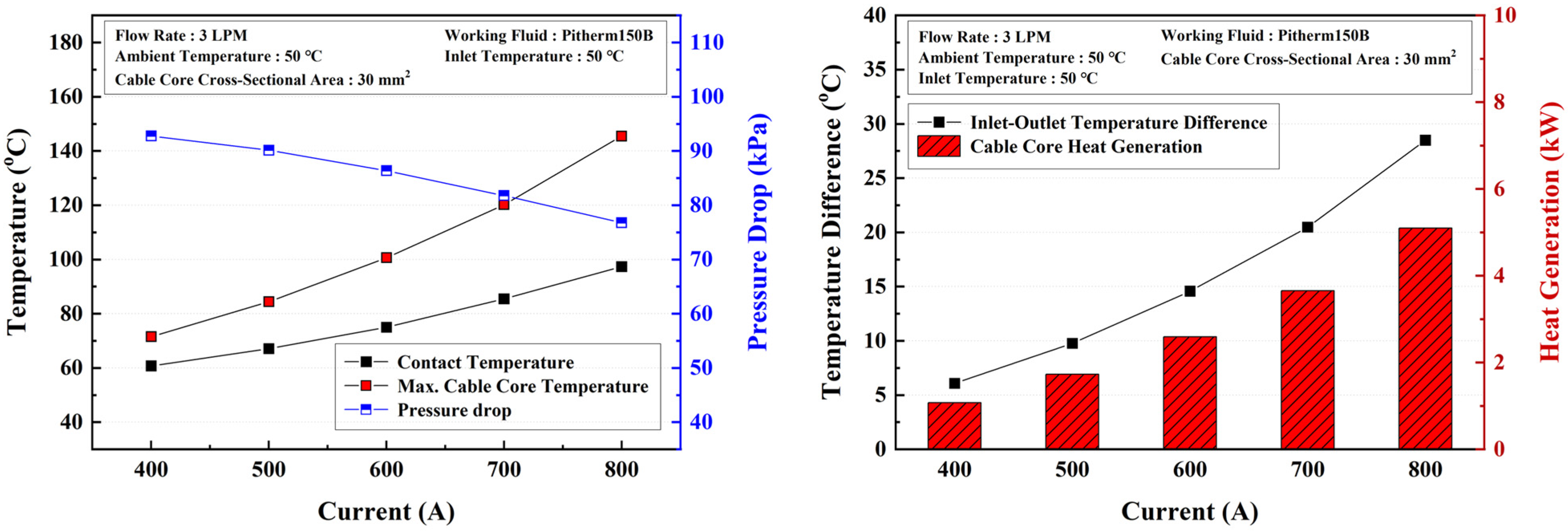
Figure 7.
Numerical analysis results for different applied currents.
The simulation results indicate that increasing the applied current leads to a corresponding rise in cable core resistance, resulting in greater heat generation. This phenomenon follows Joule’s law, which states that heat generation (P) is proportional to the square of the current (I2R). The heat generation values at different current levels demonstrate a clear trend of increasing thermal output. At 400 A, the heat generation is 1074 W, while a 100 A increase in current leads to incremental increases of 657 W, 859 W, 1063 W, and 1446 W, respectively. As a result, at 800 A, the total heat generation reaches 5099 W, indicating a substantial increase in thermal energy dissipation as current levels rise.
The thermal impact of increasing current levels is also reflected in the cable core and connector temperatures. At 400 A, the maximum cable core temperature is 71.55 °C, while the contact temperature at the connector interface is 60.73 °C, resulting in a temperature difference of 10.82 °C. However, as the current increases to 800 A, this temperature difference expands significantly to 48.17 °C, with maximum temperatures reaching 145.5 °C for the cable core and 97.33 °C for the contact temperature at the connector interface. The increase in cable core and connector temperatures with rising current levels is due to Joule heating. Higher current density increases thermal flux, causing greater heat accumulation in the cable core and contact resistance at the connector interface, leading to localized heating. As a result, the temperature difference between the core and connector expands, exacerbated by the rapid energy transfer rate in ultra-fast charging, necessitating the implementation of efficient cooling strategies to mitigate excessive temperature increases.
As the applied current increases, the coolant inlet–outlet temperature difference also exhibits a significant rise, from 6.07 °C at 400 A to 28.49 °C at 800 A. This increase is primarily due to the higher heat generation within the cable core, which transfers more thermal energy to the surrounding coolant medium. The symmetrical design ensures that heat generation and transfer are uniformly distributed around the cable core, enhancing the efficiency of heat removal. Since Joule heating follows a quadratic relationship with current, the amount of heat dissipated into the coolant increases exponentially, leading to a greater temperature rise between the inlet and outlet. Additionally, as more heat is transferred, the coolant’s thermal capacity is increasingly utilized, causing a more pronounced temperature elevation along its flow path. This effect highlights the greater thermal load at higher current levels, emphasizing the need for enhanced cooling strategies, such as higher flow rates or advanced heat exchange mechanisms, to maintain optimal temperature regulation in ultra-fast charging applications.
In addition to thermal variations, the pressure drop across the cooling system was also analyzed. The results indicate that as the current increases, the pressure drop decreases, from 92.77 kPa at 400 A to 76.77 kPa at 800 A. This reduction in pressure drop is attributed to the decrease in coolant viscosity as its temperature rises. As the coolant absorbs more heat, its viscosity decreases, leading to lower flow resistance and a corresponding reduction in pressure drop.
The results of this analysis demonstrate that higher applied currents lead to increased Joule heating, elevated cable core, connector temperatures and inlet–outlet temperature difference of the coolant, and reduced pressure drop due to viscosity changes. The symmetrical configuration of the cable core and coolant ensures consistent heat distribution and stable fluid dynamics, enhancing the effectiveness of the cooling process. These findings highlight the critical role of effective cooling strategies in high-power charging systems, particularly when operating at elevated current levels. Ensuring optimal thermal management is essential for maintaining charging efficiency, system reliability, and long-term operational safety.
3.2. Effect of Different Ambient Temperatures
This section examines the impact of varying ambient temperatures on the cooling performance of the connector and charging cable. Understanding this effect is essential because the operating environment of electric vehicle charging systems can differ significantly, influencing the thermal management efficiency of the cooling system. In high-power charging applications, the surrounding temperature plays a crucial role in determining how effectively heat is dissipated from the cable core and connectors. An increase in ambient temperature could potentially reduce the cooling system’s ability to transfer heat efficiently, affecting the overall thermal stability and safety of the system. Therefore, analyzing the relationship between ambient temperature and cooling performance is necessary to ensure optimal operation under different environmental conditions.
To evaluate the cooling performance under varying ambient temperatures, several key thermal and fluid parameters were considered. These parameters include the contact temperature at the connector interface, which reflects the heat accumulation at critical connection points, and the maximum temperature of the cable core, which is crucial for maintaining safe operating conditions. The pressure drop across the cooling system was analyzed to determine how fluid dynamics change with temperature variations, while the inlet–outlet temperature difference of the coolant was examined to assess the overall heat absorption capability of the cooling fluid.
The numerical simulations were conducted under well-defined conditions to ensure accuracy and consistency. The coolant flow rate was set at 3 LPM to maintain uniform flow characteristics across different temperature settings. The ambient temperatures were varied across four levels, 20 °C, 30 °C, 40 °C, and 50 °C, while the coolant inlet temperature was set equal to the corresponding ambient temperature to simulate real-world operating conditions. Pitherm 150B was used as the coolant due to its high thermal conductivity and stability, and the cable core area was specified as 30 mm2, ensuring consistency with previous analyses. These conditions were selected to provide a comprehensive understanding of how external temperature variations influence the performance of the cooling system.
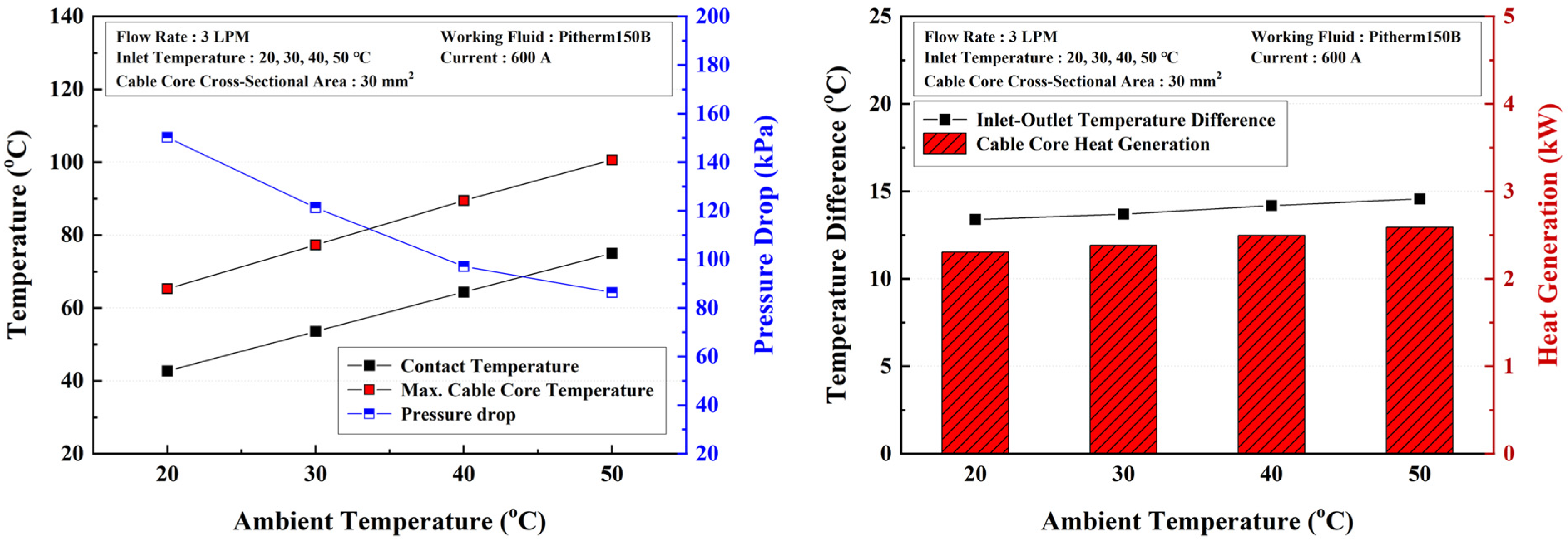
The results of the ambient temperature analysis are presented in Figure 8. The findings indicate that, under conditions where the ambient temperature and inlet temperature are identical, the temperature difference between the coolant inlet and outlet increases slightly as the ambient temperature rises. However, this effect is minimal, with the temperature difference ranging from 13.40 °C at 20 °C to 14.57 °C at 50 °C, representing an increase of only 1.17 °C. This small variation suggests that ambient temperature has a negligible effect on the overall temperature difference, implying that the cooling system benefits from its symmetrical design and maintains consistent heat absorption efficiency across different environmental conditions.

Figure 8.
Numerical analysis results for different ambient temperatures.
In contrast, as the ambient temperature increases, the heat generation of the cable core exhibits a noticeable rise, increasing from 2305 W at 20 °C to 2590 W at 50 °C. This variation is primarily due to the temperature dependence of electrical resistivity in conductive materials. As temperature increases, the resistance of the cable core rises due to increased lattice vibrations in the conductor, which impede the movement of charge carriers. Since Joule heating is directly proportional to electrical resistance, the increase in resistance leads to greater heat generation within the cable core at higher ambient temperatures. Additionally, the higher initial coolant temperature at elevated ambient conditions reduces the cooling efficiency, causing more heat to accumulate within the system.
In addition, both the contact temperature and the maximum cable core temperature also exhibit a clear dependency on ambient temperature. As the ambient temperature rises from 20 °C to 50 °C, the contact temperature increases significantly from 42.71 °C to 74.99 °C, while the maximum temperature of the cable core rises from 65.26 °C to 100.61 °C. This direct proportionality between temperature increase and ambient temperature can be attributed to the fact that as the coolant temperature increases, its ability to absorb heat from the cable core and connector diminishes, reducing the overall heat exchange efficiency. Since the cooling system relies on the temperature gradient between the cable core and the coolant to facilitate heat dissipation, a higher initial coolant temperature reduces the effectiveness of heat transfer, leading to higher operational temperatures. This effect underscores the importance of effective thermal management strategies, particularly in high-temperature environments, to prevent excessive temperature buildup and maintain stable charging performance in ultra-fast EV charging applications.
Another critical observation is the significant reduction in pressure drop with increasing ambient temperature. At 20 °C, the pressure drop across the cooling system is 150.16 kPa, but as the ambient temperature rises to 50 °C, the pressure drop decreases sharply to 86.36 kPa. This decline is primarily due to the reduction in coolant viscosity at higher temperatures. As the coolant becomes less viscous, it encounters less resistance to flow, resulting in a lower pressure drop throughout the system. This effect is particularly relevant in practical applications, as it indicates that operating at higher ambient temperatures can lead to improved fluid flow characteristics, potentially reducing the energy consumption required for coolant circulation.
The results of this analysis highlight the importance of considering ambient temperature variations when designing cooling strategies for high-power EV charging systems. While the overall temperature difference in the coolant remains relatively stable due to the advantage of the symmetrical design of the cooling system, the heat generation of the cable core, contact temperature, and cable core temperature increase significantly with rising ambient temperatures, emphasizing the need for enhanced cooling mechanisms in hot environments. Additionally, the pressure drop reduction at higher temperatures suggests that adjustments to the coolant flow rate or cooling system design may be required to maintain optimal thermal performance across different operating conditions.
3.3. Effect of Different Flow Rates
This section analyzes the impact of different coolant flow rates on the cooling performance of the connector and charging cable. Understanding this relationship is crucial, as the flow rate directly influences the efficiency of heat dissipation and the overall thermal stability of the system. A higher coolant flow rate typically enhances heat removal by increasing convective heat transfer, but it also results in greater pressure drop and increased pumping power requirements. Conversely, a lower flow rate may reduce energy consumption but could lead to insufficient cooling, potentially causing overheating in critical components. Therefore, optimizing the coolant flow rate is essential for maintaining efficient thermal management in high-power charging systems while balancing cooling effectiveness and energy consumption.
To evaluate the cooling performance under different flow rate conditions, several key thermal and fluid parameters were analyzed. The contact temperature at the connector interface was measured to assess thermal accumulation at the electrical connection point, while the maximum temperature of the cable core was monitored to ensure safe operational limits were maintained. The pressure drop across the cooling system was evaluated to determine the impact of increased flow resistance, and the inlet–outlet temperature difference of the coolant was examined to assess heat absorption efficiency. These parameters provide a comprehensive understanding of how varying flow rates influence the thermal behavior and cooling effectiveness of the system.
The numerical simulations were conducted under well-defined operating conditions to ensure accurate and reliable results. The coolant flow rates were varied with four levels: 2, 3, 4, and 5 LPM. The ambient temperature was set at 50 °C, and the coolant inlet temperature was also maintained at 50 °C to simulate realistic charging conditions. Pitherm 150B was used as the coolant due to its high thermal conductivity and stability, and the cable core area was specified as 30 mm2, ensuring consistency with previous analyses. These conditions were chosen to accurately reflect the cooling performance of the system under varying flow rates.
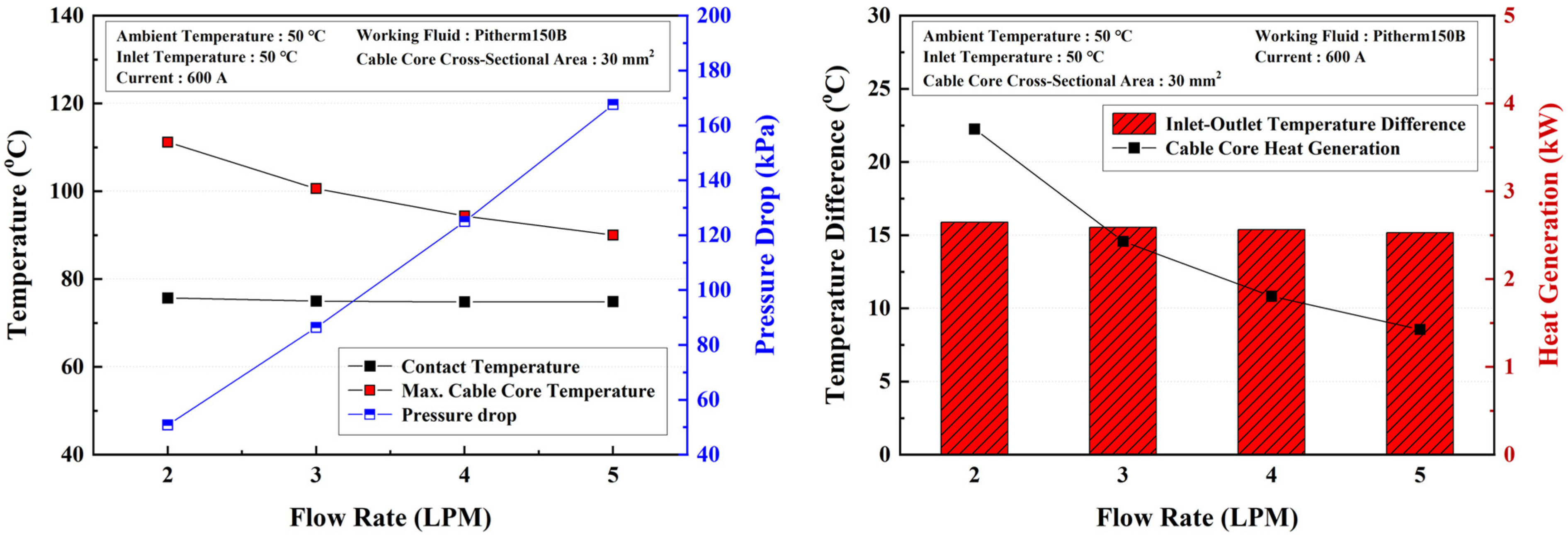
The results of the flow rate analysis are presented in Figure 9. The findings indicate that the contact temperature remained nearly constant, regardless of the increase in flow rate. At 2 LPM, the contact temperature was 75.68 °C, while at 5 LPM, it was 74.88 °C, showing a minimal difference of less than 1 °C. This negligible change suggests that the contact temperature is located in a region that is not directly cooled by the coolant, making it insensitive to variations in flow rate. As a result, increasing the flow rate has little effect on the contact temperature, and alternative thermal management strategies may be required to enhance cooling efficiency in this region.

Figure 9.
Numerical analysis results for different flow rates.
In contrast, the maximum temperature of the cable core exhibited a clear declining trend as the flow rate increased. At 2 LPM, the maximum cable core temperature was 111.18 °C, while at 5 LPM, it dropped to 90.01 °C, demonstrating a significant reduction in temperature with increased coolant flow. This decrease is attributed to the fact that the cable core benefiting from its symmetrical configuration and direct contact with the coolant, allowing for more effective and uniform convective heat transfer as the flow rate increases. Higher flow rates enhance heat removal, preventing excessive temperature buildup in the cable core and improving overall thermal performance.
Similarly, the heat generation of the cable core shows a slight decrease as the coolant flow rate increases, with values of 2647 W at 2 LPM and 2528 W at 5 LPM. This variation is primarily attributed to the temperature-dependent electrical resistance of the cable core. At lower flow rates, the cooling efficiency is reduced, leading to higher cable core temperatures. Since electrical resistivity increases with temperature, the higher operating temperature at lower flow rates results in greater resistance, thereby increasing Joule heating. Conversely, at higher flow rates, the cable core remains at a lower temperature due to improved heat dissipation, leading to slightly lower resistance and reduced heat generation. Although this change is relatively small, it highlights the importance of optimizing the coolant flow rate to maintain effective cooling and minimize unnecessary heat buildup in ultra-fast charging applications.
The inlet–outlet temperature difference of the coolant exhibited an inverse relationship with the flow rate. At 2 LPM, the temperature difference was 22.25 °C, whereas at 5 LPM, it decreased to 8.56 °C. This reduction occurs because, as the mass flow rate increases, the coolant has less time to absorb heat while passing through the system, leading to a smaller temperature rise per unit of coolant. However, despite this decrease in temperature difference, the total heat absorption capacity remains nearly constant due to the increased coolant volume flow at higher flow rates.
The pressure drop across the cooling system increased significantly as the flow rate increased, due to the rise in fluid frictional resistance. At 2 LPM, the pressure drop was measured at 50.8 kPa, but as the flow rate increased to 5 LPM, it rose sharply to 167.6 kPa, representing a more than threefold increase. This substantial rise in pressure drop is expected, as higher flow rates lead to greater turbulence and flow resistance within the system. While higher flow rates improve cooling performance, they also require more energy for fluid circulation, which must be considered when optimizing the cooling system for efficiency and sustainability.
The results of this analysis highlight the importance of optimizing flow rate in high-power EV charging systems. While higher flow rates significantly reduce the maximum cable core temperature owing to the merit of the symmetrical design of the cooling system, they also lead to increased pressure drop, requiring greater energy input for coolant circulation. Additionally, the contact temperature remains largely unaffected, suggesting that improvements in cooling efficiency at the connector interface may require alternative design modifications rather than simply increasing the flow rate. By balancing cooling performance, pressure drop, and energy efficiency, an optimal flow rate can be identified to enhance the overall thermal management of the system while minimizing unnecessary energy consumption.
3.4. Effect of Different Cable Core Cross-Sectional Areas
This section examines the influence of varying cable core cross-sectional areas on the cooling performance of the charging system. The cable core cross-sectional area is a critical factor in determining electrical resistance, current density, and heat generation within the conductor. A smaller cross-sectional area results in higher current density, leading to greater Joule heating and higher operating temperatures. Conversely, a larger cross-sectional area reduces resistance and heat generation, which can improve thermal performance. However, increasing the core size also affects fluid dynamics, particularly pressure drop and coolant flow behavior. Therefore, analyzing the effect of different cable core cross-sectional areas is essential for optimizing both thermal management and fluid dynamics in high-power electric vehicle charging systems.
To evaluate the cooling performance under different cable core sizes, several key parameters were considered. The contact temperature at the connector interface was measured to assess heat accumulation at the electrical connection point. The maximum temperature of the cable core was analyzed to determine how changes in wire thickness influenced thermal behavior. The pressure drop across the cooling system was evaluated to understand the impact of varying core sizes on fluid resistance. Additionally, the inlet–outlet temperature difference of the coolant was examined to assess heat absorption efficiency in different configurations. These parameters provide a comprehensive understanding of how variations in cable core size affect cooling efficiency and system performance.
The numerical simulations were conducted under well-defined conditions to ensure accurate and reliable results. The coolant flow rate was maintained at 3 LPM, with an ambient temperature of 50 °C and a coolant inlet temperature of 50 °C to simulate realistic operating conditions. Pitherm 150B was used as the coolant due to its high thermal conductivity and stability. The analysis was performed for three different cable core cross-sectional areas: 20, 25, and 30 mm2, allowing for a comparative evaluation of how varying conductor sizes affect thermal and fluid dynamics.
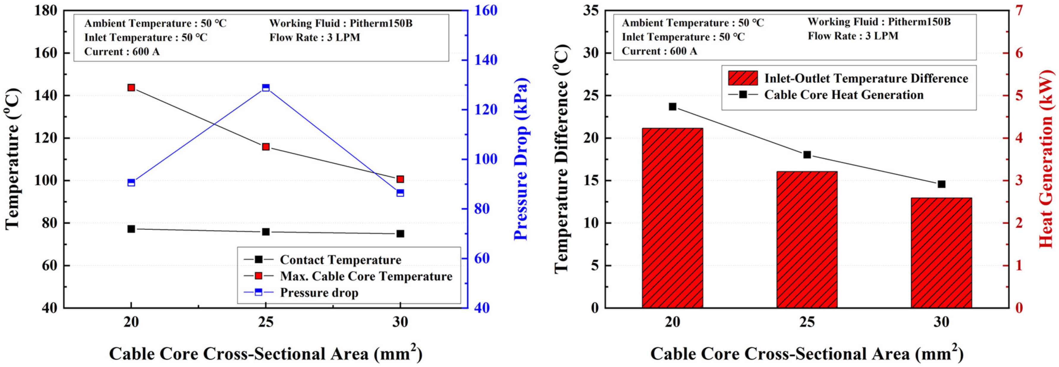
The results of the cable core cross-sectional area analysis are presented in Figure 10. The findings indicate that the contact temperature remained nearly constant, despite variations in cable core size. At 20 mm2, the contact temperature was 77.20 °C, while at 30 mm2, it measured 74.99 °C, showing a difference of less than 1.5 °C. This minimal variation suggests that the contact temperature is located in a region that is not directly cooled by the coolant, making it less sensitive to changes in cable core thickness. As a result, modifying the core size has little impact on the thermal behavior of the contact region and alternative cooling strategies may be required to enhance thermal performance in this area.

Figure 10.
Numerical analysis results for different cable core cross-sectional areas.
In contrast, the maximum cable core temperature exhibited a significant decline as the cross-sectional area increased. At 20 mm2, the maximum cable core temperature was 143.7 °C, decreasing to 115.85 °C at 25 mm2, and further dropping to 100.61 °C at 30 mm2. This progressive temperature reduction can be attributed to the inverse relationship between current density and cross-sectional area. A smaller conductor results in higher current density, leading to greater Joule heating and elevated temperatures. As the cable core size increases, the electrical resistance decreases, reducing heat generation and enhancing thermal performance.
Similarly, the heat generation of the cable core also decreases significantly as the cable core cross-sectional area increases, dropping from 4230 W at 20 mm2 to 2590 W at 30 mm2. This variation is primarily due to the inverse relationship between electrical resistance and conductor cross-sectional area. According to Ohm’s law (R = ρL/A), increasing the cross-sectional area (A) reduces the electrical resistance (R) of the conductor. Since Joule heating is directly proportional to resistance, a larger cable core results in lower resistance, leading to less heat generation at the same applied current. Additionally, a larger core area distributes the current density more evenly, reducing localized overheating and improving thermal performance. This finding underscores the importance of optimizing cable core size to minimize heat generation, enhance charging efficiency, and ensure safe operation in ultra-fast EV charging systems.
In addition, the inlet–outlet temperature difference of the coolant also decreases as the cable core cross-sectional area increases, from 23.69 °C at 20 mm2 to 14.57 °C at 30 mm2. This variation is primarily due to the reduction in heat generation as the cable core size increases. Since Joule heating is directly proportional to electrical resistance, a larger core cross-sectional area lowers resistance, resulting in less heat dissipation into the coolant. Consequently, with reduced thermal energy transferred, the temperature rise of the coolant along the flow path is lower. Additionally, the symmetrical design improves coolant distribution, minimizing localized heating and contributing to a more uniform thermal profile.
The pressure drop within the cooling system was also significantly affected by changes in the cable core cross-sectional area. When using the same tube diameter of 10 mm, the pressure drop at 20 mm2 was 90.57 kPa, while at 25 mm2, it increased to 128.83 kPa. The higher pressure drop in the 25 mm2 configuration is due to the reduced effective flow area for the coolant. As the cable core size increases, the available space for coolant flow decreases, resulting in a smaller hydraulic diameter and greater resistance to flow, which in turn increases pressure loss. However, for the 30 mm2 configuration, a larger tube with an 11 mm inner diameter was used, allowing for smoother fluid flow. As a result, despite the larger core size, the pressure drop in the 30 mm2 condition was relatively lower compared to the 25 mm2 configuration at 86.36 kPa, demonstrating the importance of adjusting tube diameter to accommodate larger conductors without excessively increasing flow resistance.
The results of this study highlight the critical role of cable core size in thermal and fluid performance. While larger cable cores effectively reduce heat generation and maximum temperature, they can also lead to higher pressure drops if the cooling system is not properly adjusted. The findings suggest that selecting an optimal cable core size, along with an appropriate tube diameter, is essential for balancing cooling efficiency and fluid resistance in high-power EV charging systems. By carefully considering the trade-offs between thermal performance, electrical efficiency, fluid dynamics and system symmetry, engineers can optimize cable design to ensure safe and efficient charging across different operating conditions.
3.5. Effect of Different Coolants
This section examines the impact of different coolants on the thermal and fluid performance of the charging system. The choice of coolant plays a critical role in determining the efficiency of heat transfer, pressure drop, and overall cooling effectiveness. Different coolants possess unique thermal properties, such as specific heat capacity, viscosity, and thermal conductivity, which directly influence their ability to absorb and dissipate heat. Therefore, evaluating the effect of various coolants is essential for selecting the most efficient cooling fluid for high-power electric vehicle charging applications. By analyzing the cooling performance of different coolants, an optimal coolant can be identified to enhance heat dissipation, minimize overheating risks, and improve system reliability.
To assess the cooling performance of different coolants, several key thermal and fluid parameters were examined. The contact temperature at the connector interface was measured to determine heat accumulation at the electrical connection point, while the outlet coolant temperature was analyzed to assess the heat transfer efficiency of each working fluid. Additionally, the Nusselt number (Nu) was evaluated as an indicator of convective heat transfer performance, and the friction factor (f) was analyzed to determine the flow resistance of each coolant. Finally, the performance evaluation criteria (PEC) were used to compare the overall cooling effectiveness of different coolants by considering both heat transfer enhancement and flow resistance.
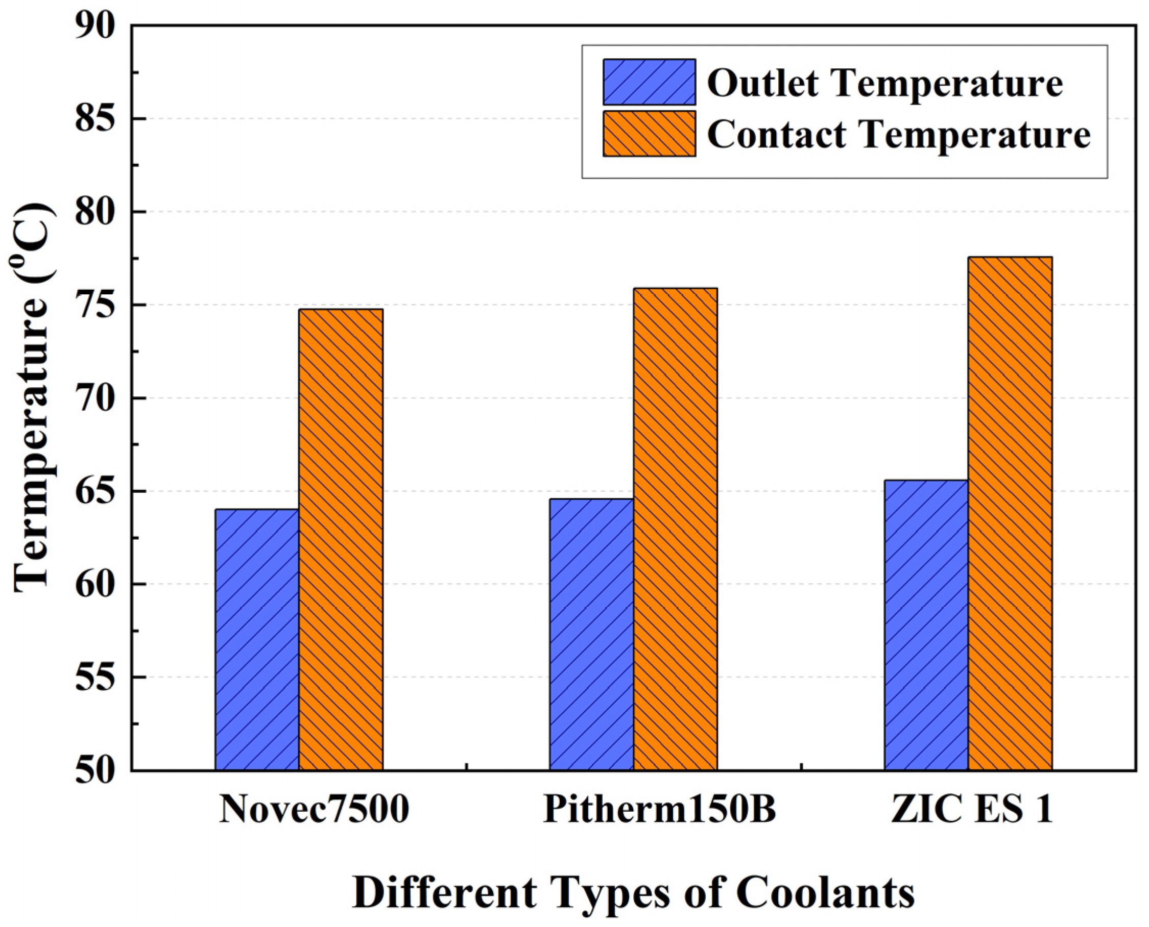
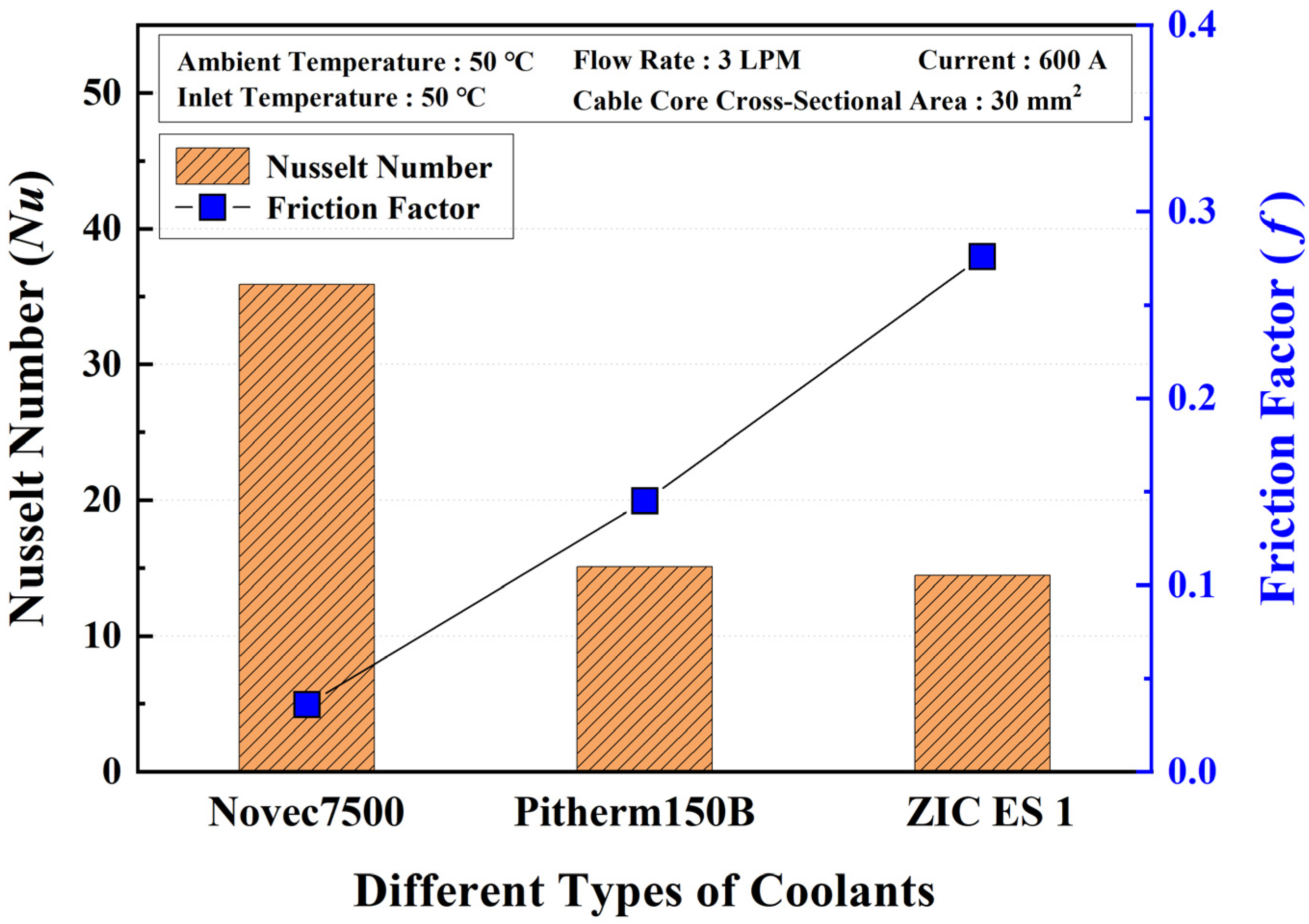
The numerical simulations were conducted under consistent operating conditions to ensure an accurate comparison of coolant performance. The coolant flow rate was set at 3 LPM, with an ambient temperature of 50 °C and a coolant inlet temperature of 50 °C to replicate realistic high-temperature charging conditions. The coolants analyzed in this study included Novec 7500, Pitherm 150B, and ZIC ES 1, each of which possesses distinct thermal and fluid properties. The cable core cross-sectional area was set at 30 mm2, and a current value of 600 A was applied to ensure significant heat generation, enabling a comprehensive evaluation of cooling efficiency and fluid dynamics.
The results of the contact temperature and outlet coolant temperature for different coolants are presented in Figure 11. The analysis reveals that Novec 7500 exhibited the lowest temperatures, with a contact temperature of 74.76 °C and an outlet temperature of 63.99 °C. In contrast, ZIC ES 1 showed the highest values, with a contact temperature of 77.57 °C and an outlet temperature of 65.57 °C. However, the temperature difference between Novec 7500 and ZIC ES 1 was less than 3 °C, indicating that the variations in cooling performance between the different coolants were relatively minor.

Figure 11.
Variation in contact temperature and outlet temperature with different coolants.
The differences in temperature distribution can be attributed to variations in the heat capacity rate of each coolant. Considering the mass flow rate and specific heat capacity of each coolant, the heat capacity rates were ranked in the following order: Novec 7500 (90.99 W/K), Pitherm 150B (88.86 W/K), and ZIC ES 1 (78.86 W/K). The heat capacity rate difference between Novec 7500 and ZIC ES 1 was approximately 13.33%, explaining the slight variations in temperature performance. This difference in heat capacity rate directly affects the cooling effectiveness of each coolant, as a higher heat capacity rate allows for greater heat absorption and improved temperature regulation along with the outstanding advantage of symmetrical design in the cooling system.
The Nusselt number (Nu) and friction factor (f) were further analyzed to evaluate the convective heat transfer performance and flow resistance characteristics of each coolant. The results, illustrated in Figure 12, show that Novec 7500 exhibited the highest Nusselt number (35.89), followed by Pitherm 150B (15.08) and ZIC ES 1 (14.46). This indicates that Novec 7500 offers the most efficient heat transfer performance, with a convective heat transfer capability nearly 2.5 times higher than Pitherm 150B and three times higher than ZIC ES 1. The superior heat transfer of Novec 7500 is attributed to its lower viscosity and enhanced convective properties, which allow for more efficient thermal exchange between the fluid and the heated surfaces. Despite similar cooling performance among the coolants, the particularly low Nusselt number of Novec 7500 can be attributed to its thermal conductivity and density. The density of Novec 7500 at 40 °C is 1547 kg/m3, which is 2.02 times and 1.88 times greater than that of Pitherm 150B (766.8 kg/m3) and ZIC ES 1 (820.9 kg/m3), respectively. This results in an increase in mass flow rate for the same volumetric flow rate, compensating for the disadvantage of Novec 7500 is low specific heat capacity (1176.4 J/kg·K) in terms of heat transfer performance. Consequently, the convective heat transfer coefficient (U) is 653.7 W/m2·K for Novec 7500, 615.7 W/m2·K for Pitherm 150B, and 564.3 W/m2·K for ZIC ES 1, indicating that the convective heat transfer performance of Novec 7500 is 6.17% and 15.85% higher than that of Pitherm 150B and ZIC ES 1, respectively. Conversely, the friction factor (f), which quantifies flow resistance, was lowest for Novec 7500 (0.036), significantly lower than Pitherm 150B (0.145) and ZIC ES 1 (0.276). The higher friction factors of Pitherm 150B and ZIC ES 1 indicate greater flow resistance, resulting in higher pressure drop and increased energy consumption for fluid circulation. In contrast, Novec 7500’s lower friction factor suggests smoother fluid flow with reduced pressure losses, further enhancing its overall cooling efficiency.

Figure 12.
Variation in Nusselt number and friction factor with different coolants.
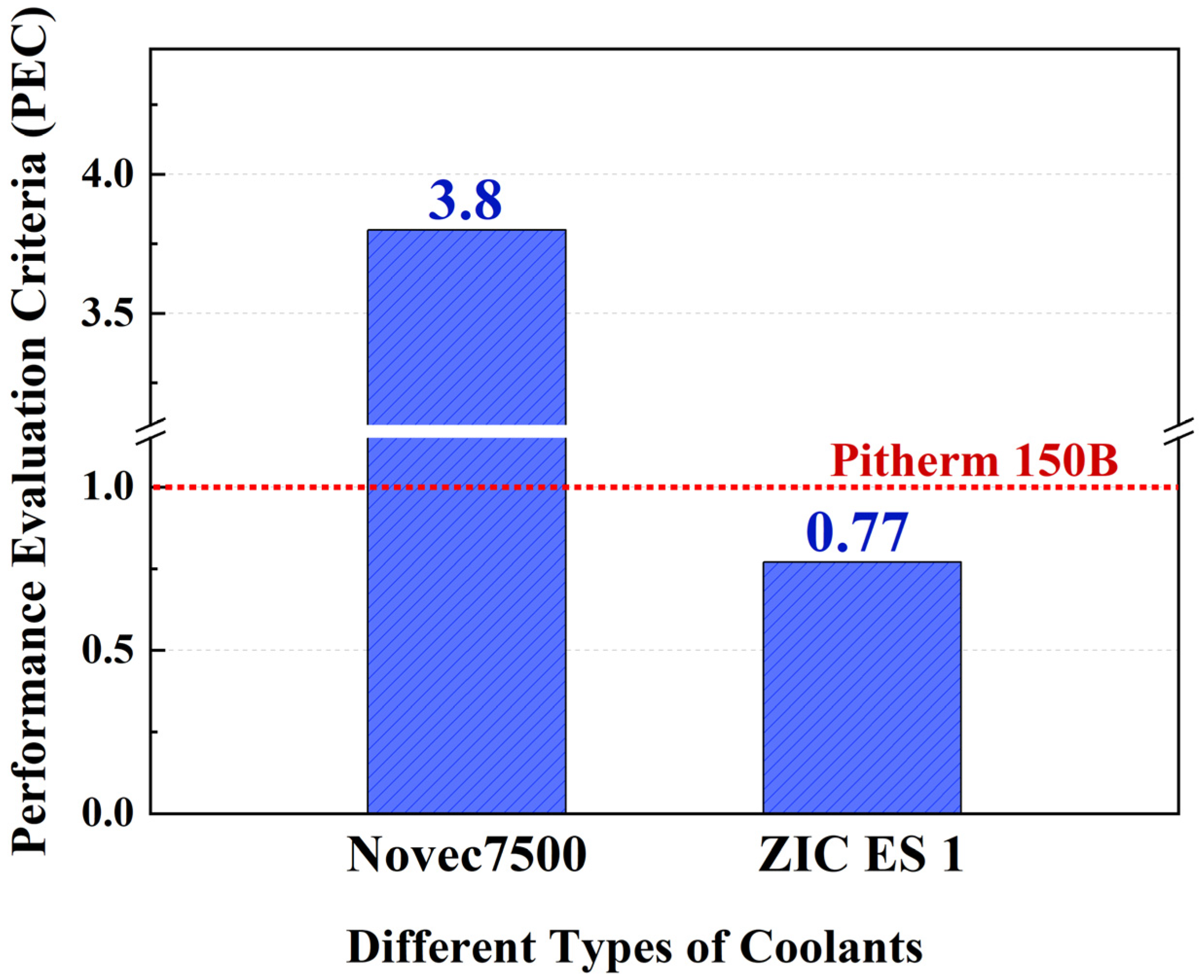
To comprehensively compare the overall cooling effectiveness of each coolant, the PEC was analyzed, as presented in Figure 13. Using Pitherm 150B as the reference coolant with a PEC value of 1, the results showed that Novec 7500 had a PEC value of 3.8, while ZIC ES 1 had the lowest PEC value of 0.77. This indicates that Pitherm 150B exhibited approximately 29.87% higher PEC than ZIC ES 1, while Novec 7500 demonstrated a PEC value nearly four times higher than Pitherm 150B. The high PEC value of Novec 7500 is primarily due to its significantly lower viscosity, which is approximately four times lower than that of Pitherm 150B. A lower viscosity reduces frictional losses, leading to lower pressure drop and improved flow characteristics, while also enhancing convective heat transfer efficiency. Conversely, ZIC ES 1 exhibited the lowest PEC value, suggesting that it has higher flow resistance and lower heat transfer efficiency, making it the least effective coolant among those tested.
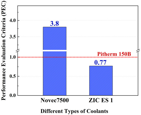
Figure 13.
Variation in PEC with different coolants.
These findings emphasize the importance of selecting an optimal coolant for high-power EV charging systems. While all three coolants exhibited relatively small differences in temperature performance, Novec 7500 demonstrated superior cooling efficiency due to its higher heat capacity rate, enhanced convective heat transfer, and lower viscosity, resulting in reduced frictional losses and improved overall system performance. In contrast, ZIC ES 1 showed the lowest cooling efficiency, primarily due to its higher viscosity and lower heat transfer characteristics. Therefore, selecting a coolant with favorable thermal and fluid properties combined with a symmetrical cooling system design to further ensure uniform fluid flow is essential for ensuring efficient heat dissipation, minimal energy losses, and reliable system operation in high-power charging applications.
A comparison between the present results and those reported in the literature on immersion cooling systems for ultra-fast EV chargers was conducted. Devahdhanush et al. employed a two-phase immersion cooling method using HFE-7100 and recorded a peak temperature of 85 °C under high current conditions [10]. Zhiping Zou et al. investigated a single-phase immersion cooling system designed for megawatt-level charging and achieved a temperature of approximately 75 °C [30]. Similarly, Brakelmann et al. demonstrated that an immersion cooling system for 230 kV cross-linked polyethylene cables was able to maintain operating temperatures below 85 °C [31]. In comparison, the present study using Novec 7500 as the cooling fluid achieved a maximum contact temperature of 74.76 °C, indicating superior thermal performance. This suggests that Novec 7500 offers advantages in terms of thermal conductivity and viscosity compared to other fluids reported in the literature. Nonetheless, there remains significant potential to further enhance cooling efficiency by exploring next-generation dielectric fluids with improved thermal and flow properties. Future research should focus on developing and evaluating advanced coolants that can offer higher performance, reduced system complexity, and improved reliability for high-power EV charging applications.
3.6. Transient Thermal-Fluid Analysis Under Realistic Fast-Charging Duration
To better reflect the dynamic thermal behavior of the immersion cooling system under realistic operating conditions, a transient thermal-fluid simulation was conducted. The simulation duration was set to 10 min, which corresponds to the approximate time required for the ultra-fast charging of electric vehicles in practical applications today. This time frame serves as a representative benchmark for evaluating the short-term thermal response of the system during high-power charging sessions. The simulation was performed under a constant current of 600 A, with the cable core cross-sectional area set to 30 mm2. Novec 7500, a dielectric coolant known for its favorable thermal properties, was selected as the working fluid. The coolant flow rate was maintained at 3 LPM with an inlet temperature of 50 °C, and the ambient temperature was also set at 50 °C to replicate thermally demanding conditions. This transient analysis provides insights into the system’s ability to manage heat buildup over time and supports the evaluation of cooling system performance under time-dependent operational scenarios commonly encountered in real-world fast-charging applications.
The results of the transient simulation of temperature variation and pressure drop are shown in Figure 14. As the coolant travels along the flow path and absorbs heat from the cable core, its temperature gradually increases. After 150 s, the outlet temperature stabilizes at an average of approximately 63 °C, indicating that the thermal response of the cable core reaches a quasi-steady state after this time frame. Unlike the outlet temperature, which stabilizes quickly due to forced convection by the coolant, the contact temperature strongly rises the first 150 s at 68.29 °C, eventually reaching 74.61 °C at 10 min. This delayed stabilization is attributed to slower convective cooling from the surrounding air, requiring a longer time for thermal equilibrium to be achieved in externally exposed regions. In addition, the pressure drop increases rapidly, reaching an average of 47.12 kPa within the first 15 s. After that, the pressure drop value reaches a steady state due to the uniform distribution of the coolant and the cable core reaches a steady thermal state.
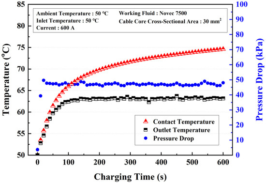
Figure 14.
Temperature and pressure drop variation according to charging time.
These transient results confirm that thermal equilibrium in the cable core is reached relatively quickly due to the efficient forced convection provided by the dielectric coolant. In contrast, the slower stabilization of the contact temperature indicates that external surfaces cooled by ambient air are more susceptible to delayed thermal response. This distinction implies that while the internal cable structure benefits from immersion cooling, components exposed to air may experience thermal lag, potentially affecting material aging or long-term reliability. Additionally, although the system stabilizes thermally within a few minutes, initial pressure behavior must still be considered when selecting pump specifications, particularly for high-current charging applications.
4. Conclusions
The findings of this study offer valuable guidance for the future development of EV charger cooling systems. Numerical analyses demonstrated that immersion cooling with an optimized configuration and suitable coolant selection can effectively manage the high thermal loads of ultra-fast charging. Identifying optimal operating conditions such as applied current, ambient temperature, coolant flow rate, cable core cross-sectional area and coolant type supports the development of safer and more energy-efficient systems. The focus on geometric symmetry also offers a practical design approach to achieve uniform heat distribution and reduce thermal stress. These insights support the development of reliable and high-performance thermal management strategies for next-generation EV charging systems. The key findings are summarized as follows:
- (a)
- As the applied current increased, the electrical resistance of the cable core also rose, leading to a nonlinear increase in heat generation. The heat generation escalated from 1074 W at 400 A to 5099 W at 800 A, following Joule’s law, which states that heat generation is proportional to the square of the current (I2R).
- (b)
- The temperature difference between the coolant inlet and outlet increased by a maximum of 1.17 °C with rising ambient temperature, indicating that ambient conditions had a minimal effect on coolant heat absorption. However, the contact temperature and maximum cable core temperature increased proportionally to the ambient temperature.
- (c)
- Increasing the coolant flow rate resulted in a lower maximum cable core temperature and reduced inlet–outlet temperature difference, improving overall cooling performance. However, the fluid velocity and frictional resistance increased at higher flow rates, leading to a significant rise in pressure drops due to enhanced flow turbulence and shear forces.
- (d)
- As the current increased, the pressure drop decreased, primarily due to the reduction in fluid viscosity caused by higher fluid temperatures. In addition, increasing the cable core cross-sectional area led to a decrease in maximum cable core temperature and heat generation, while the contact temperature remained nearly constant.
- (e)
- Among the coolants tested, Novec 7500 exhibited the highest Nusselt number (Nu) and lowest friction factor (f), resulting in the highest PEC value of 4.05. The superior performance of Novec 7500 is attributed to its low viscosity and high thermal conductivity, which collectively enhance convective heat transfer efficiency while minimizing flow resistance.
The simulations conducted in this study were limited to specific current ranges (400 A to 800 A) and ambient temperatures. To enhance the understanding of cooling performance under various real-world conditions, future studies should expand the range of operating conditions, including higher current levels and more extreme environmental temperatures. Additionally, while Novec 7500 demonstrated excellent thermal performance in this study, exploring the thermal and flow properties of next-generation dielectric fluids could offer significant improvements in cooling efficiency, reduce system complexity, and enhance the overall performance of the cooling system. Moreover, the application of artificial intelligence (AI) can optimize the performance of the immersion cooling system in real time during the cooling process. Machine learning algorithms can be used to dynamically adjust coolant flow and operating parameters based on real-time thermal data and environmental conditions. By integrating sensor networks across the entire charging system, AI can predict temperature fluctuations and automatically adjust cooling settings to prevent overheating, thereby improving system efficiency and extending the life of both the cable and the coolant of the ultra-fast charging infrastructure.
Author Contributions
Conceptualization, S.-G.H. and M.-Y.L.; methodology, S.-G.H. and M.-Y.L.; formal analysis, S.-G.H. and M.-Y.L.; investigation, S.-G.H., B.-S.K. and M.-Y.L.; resources, S.-G.H., B.-S.K. and M.-Y.L.; data curation, S.-G.H. and M.-Y.L.; writing—original draft preparation, S.-G.H.; writing—review and editing, S.-G.H., B.-S.K. and M.-Y.L.; visualization, S.-G.H., B.-S.K. and M.-Y.L.; supervision, M.-Y.L.; project administration, M.-Y.L.; funding acquisition, M.-Y.L. All authors have read and agreed to the published version of the manuscript.
Funding
The authors declare that this study received funding from YURA Co., Ltd. (Republic of Korea), the National Research Foundation of Korea (NRF) grant funded by the Korea government (MSIT) (No. 2020R1A2C1011555) and the Korea Evaluation Institute of Industrial Technology (KEIT) grant funded by the Korean government (MOTIE) (No. 20024894). The funder had the following involvement with the study: investigation, resources, writing—review and editing, visualization.
Data Availability Statement
The data presented in this study will be available on request to the corresponding author.
Conflicts of Interest
Author Beom-Seok Ko was employed by the company Yura Co., Ltd. The authors declare that this study received funding from YURA Co., Ltd. (Republic of Korea). The remaining authors declare that the research was conducted in the absence of any commercial or financial relationships that could be construed as a potential conflict of interest.
References
- Feng, R.; Yu, J.; Shu, X.; Deng, B.; Hua, Z. Can the world harmonized steady cycle (WHSC) accurately reflect real-world driving conditions for heavy-duty diesel engine emission valuations? A comprehensive experimental study. Therm. Sci. Eng. Prog. 2025, 59, 103321. [Google Scholar] [CrossRef]
- Suresh, C.; Awasthi, A.; Kumar, B.; Im, S.; Jeon, Y. Advances in battery thermal management for electric vehicles: A comprehensive review of hybrid PCM-metal foam and immersion cooling technologies. Renew. Sustain. Energy Rev. 2025, 208, 115021. [Google Scholar] [CrossRef]
- Wu, X.; Lu, Y.; Ouyang, H.; Ren, X.; Yang, J.; Guo, H.; Han, X.; Zhang, C.; Wu, Y. Theoretical and experimental investigations on liquid immersion cooling battery packs for electric vehicles based on analysis of battery heat generation characteristics. Energy Convers Manag. 2024, 310, 118478. [Google Scholar] [CrossRef]
- Han, J.-W.; Hwang, S.-G.; Garud, K.S.; Lee, M.-S.; Lee, M.-Y. Numerical Study on Oil Cooling Performance of the Cylindrical Lithium-Ion Battery Pack with Flow Arrangement. J. Korea Acad. Ind. Coop. Soc. 2022, 23, 19–25. [Google Scholar] [CrossRef]
- Tai, L.D.; Garud, K.S.; Lee, M. Experimental Study on Thermal Management of 5S7P Battery Module with Immersion Cooling Under High Charging/Discharging C-Rates. Batteries 2025, 11, 59. [Google Scholar] [CrossRef]
- Suarez, C.; Martinez, W. Fast and Ultra-Fast Charging for Battery Electric Vehicles—A Review. In Proceedings of the 2019 IEEE Energy Conversion Congress and Exposition (ECCE), Baltimore, MD, USA, 28 November 2019. [Google Scholar] [CrossRef]
- Choi, D.; Kim, M.; Yu, J.; Hong, D. Experimental Study on the Heat Charging and Discharging Characteristics of a Heat Absorption Device Applied to the Cooling System of Electric Vehicle Chargers. J. Korea Acad. Ind. Coop. Soc. 2024, 25, 536–542. [Google Scholar] [CrossRef]
- Wu, Y.; Yu, H.; Zhang, J.; Xu, X.; Dai, R.; Liu, W.; Lv, H.; Xu, Y.; Wang, Q.; He, H.; et al. Optimal design of liquid cooling structures for superfast charging cable cores under a high current load. Case Stud. Therm. Eng. 2023, 53, 103821. [Google Scholar] [CrossRef]
- Fu, C.Z.; Si, W.R.; Quan, L.; Yang, J. Numerical study of convection and radiation heat transfer in pipe cable. Int. J. Math. Probl. Eng. 2018, 1155, 5475136. [Google Scholar] [CrossRef]
- Devahdhanush, V.S.; Lee, S.; Mudawar, I. Experimental investigation of subcooled flow boiling in annuli with reference to thermal management of ultra-fast electric vehicle charging cables. Int. J. Heat Mass Transfer. 2021, 172, 121176. [Google Scholar] [CrossRef]
- Hong, D.; Choi, D.; Kong, S.; Kim, T.; Lim, K. Experimental Study on the Performance of an Charger Cooling System for Electric Vehicles. J. Korea Acad. Ind. Coop. Soc. 2022, 23, 676–681. [Google Scholar] [CrossRef]
- Choi, D.; Kim, T.; Kim, M.; Yu, J.; Hong, D. Experimental Study on the Thermal Characteristics and Melting Behavior of Phase Change Materials Applied to the Cooling System of Electric Vehicle Chargers. J. Korea Acad. Ind. Coop. Soc. 2024, 25, 349–356. [Google Scholar] [CrossRef]
- Dai, H.; Yang, C.; Zhang, F.; Liao, G.; Zhang, B.; E, J. Transient heat dissipation performance investigation on the battery thermal management system based on S-CO2 immersion cooling. Energy 2025, 318, 134656. [Google Scholar] [CrossRef]
- Tong, B.; Shi, J.; Cao, M.; Xuan, W.; Chen, J.; Jin, K.; Sun, J.; Wang, Q. Comprehensive comparison study on battery thermal management modules with indirect and direct liquid cooling. Appl. Therm. Eng. 2025, 268, 125945. [Google Scholar] [CrossRef]
- Ye, J.; Huang, J.; Xia, Y.; Li, R. Improve immersion cooling of cylindrical batteries in channel flows using the Tesla valve principle. J. Energy Storage 2025, 112, 115546. [Google Scholar] [CrossRef]
- Wahab, A.; Najmi, A.; Senobar, H.; Amjady, N.; Kemper, H.; Khayyam, H. Immersion cooling innovations and critical hurdles in Li-ion battery cooling for future electric vehicles. Renew. Sustain. Energy Rev. 2025, 211, 115268. [Google Scholar] [CrossRef]
- Shi, H.; Zeng, Z.; Kong, B.; Yuan, N. Enhancing high-density battery performance through innovative single-phase spray technology in immersion cooling systems. J. Power Sources 2025, 626, 235770. [Google Scholar] [CrossRef]
- Garud, K.S.; Tai, L.D.; Hwang, S.; Nguyen, N.; Lee, M. A Review of Advanced Cooling Strategies for Battery Thermal Management Systems in Electric Vehicles. Symmetry 2023, 15, 1322. [Google Scholar] [CrossRef]
- Li, Y.; Bai, M.; Zhou, Z.; Wu, W.; Lv, J.; Gao, L.; Huang, H.; Li, Y.; Li, Y.; Song, Y. Experimental investigations of liquid immersion cooling for 18650 lithium-ion battery pack under fast charging conditions. Appl. Therm. Eng. 2023, 227, 120287. [Google Scholar] [CrossRef]
- Chandrasekaran, M.; Jithin, K.V.; Soundarya, T.; Rajesh, P.K. Comprehensive experimental study of battery thermal management using single-phase liquid immersion cooling. J. Energy Storage 2025, 111, 115445. [Google Scholar] [CrossRef]
- Kim, J.; Choi, H.; Lee, S.; Lee, H. Computational study of single-phase immersion cooling for high-energy density server rack for data centers. Appl. Therm. Eng. 2025, 264, 125476. [Google Scholar] [CrossRef]
- Wu, X.; Yang, J.; Liu, Y.; Zhuang, Y.; Luo, S.; Yan, Y.; Xiao, L.; Han, X. Investigations on heat dissipation performance and overall characteristics of two-phase liquid immersion cooling systems for data center. Int. J. Heat Mass Transf. 2025, 239, 126575. [Google Scholar] [CrossRef]
- Peng, S.; Hen, Z.; Fa-Chao, J.; Zhi-Zhu, H. Self-driven liquid metal cooling connector for direct current high power charging to electric vehicle. Etransportation 2021, 10, 100132. [Google Scholar] [CrossRef]
- Incropera, F.P.; DeWitt, D.P.; Bergman, T.L.; Lavine, A.S. Fundamentals of Heat and Mass Transfer, 8th ed.; Wiley: Hoboken, NJ, USA, 2022; pp. 132–259. [Google Scholar]
- 3M Novec 7500 Engineered Fluid Technical Data Sheet. Available online: https://multimedia.3m.com/mws/media/65496O/3m-novec-7500-engineered-fluid.pdf (accessed on 25 February 2025).
- Pitherm Chemical Co., Ltd. PITHERM 150B Product Data Sheet; Pitherm Chemical Co., Ltd.: Seoul, Republic of Korea, 2025. [Google Scholar]
- SK Enmove Co., Ltd. ZIC e-FLO Thermal Fluids Technical Data Sheet; SK Enmove Co., Ltd.: Seoul, Republic of Korea, 2025. [Google Scholar]
- ODA Technologies. Product Catalog; ODA Technologies: Incheon, Republic of Korea, 2023. [Google Scholar]
- Keysight Technologies. 34970A Data Acquisition/Switch Unit Technical Data Sheet; Keysight Technologies: Santa Rosa, CA, USA, 2025. [Google Scholar]
- Zou, Z.; Wang, J.; Pang, Y.; Ding, J.; Lu, Z.; Zhang, K.; Wan, S. Research on the Design and Temperature Rise Performance of Megawatt-level Ultra-high Current Charging Connection Components for Electric Vehicles. J. Phys. Conf. Ser. 2024, 2785, 012115. [Google Scholar] [CrossRef]
- Brakelmann, H.; Anders, G.J. Analysis of the Three-dimensional Temperature Distribution of Forced Cooled Power Cables. IEEE Trans. Power Deliv. 2022, 37, 736–744. [Google Scholar] [CrossRef]


Disclaimer/Publisher’s Note: The statements, opinions and data contained in all publications are solely those of the individual author(s) and contributor(s) and not of MDPI and/or the editor(s). MDPI and/or the editor(s) disclaim responsibility for any injury to people or property resulting from any ideas, methods, instructions or products referred to in the content. |
© 2025 by the authors. Licensee MDPI, Basel, Switzerland. This article is an open access article distributed under the terms and conditions of the Creative Commons Attribution (CC BY) license (https://creativecommons.org/licenses/by/4.0/).