Abstract
In the age of big data, multimedia communication is becoming one of the most important communication methods. Therefore, it is important to overcome the challenge of processing numerous images safely and efficiently. In this paper, a 3D cross-image encryption scheme is proposed based on the Rubik’s Cube–poker model. The proposed scheme has the following properties: Firstly, it has flexible input image requirements to improve its applicability. Secondly, it has a strong ability to recover from data loss and retains important information in the reconstructed image. Finally, it achieves a lower time cost. Under the same input conditions in the grayscale color space, our proposed scheme achieves an execution time of 0.62 s, which is significantly lower than that of other schemes. The simulation results confirm the correctness, security, and robustness of the scheme.
1. Introduction
With the rapid development of Internet technology and multimedia technology, multimedia communication based on images has gradually become an important means for modern people to exchange information. Therefore, it is crucial to conduct research on image information security protection technologies.
Image encryption, steganography, and watermarks are the three main techniques for protecting the security of digital images. Important text or image information will be hidden by steganography, which embeds the information in the carrier [1,2,3,4,5]. Image watermarks can successfully safeguard the copyright of artistic creations by providing authentication information incorporated in the image [6,7,8,9]. Image encryption turns the original image into noise-like snowflake images by using scrambling and diffusion [10,11,12].
The development of encryption techniques specifically for images is challenging because traditional text encryption methods, such as DES, AES, and RSA, face several issues when applied to images, including a high time cost, strong correlation, and poor diffusion and scrambling performance. To overcome these limitations, chaos theory has been introduced into the design of image encryption schemes, providing new directions for secure and efficient encryption models. It is a challenge to design a multi-image encryption scheme which has both a low time cost and high pixel perturbation. We suggest a 3D multi-image encryption scheme based on the Rubik’s Cube-and-poker model. Our scheme has the following properties:
- Scheme principle The scheme is based on the principle of the Rubik’s Cube-and-poker model, which provides a vast number of states. It can change the positions of a large number of pixels with simple operations in order to achieve the aim of balancing the time cost and scrambling effects.
- Input flexibility In many existing 3D multi-image encryption schemes, the input image must be able to construct an cube. In our scheme, we also propose a solution for a general case, and we can encrypt any number and size of input images at the same time.
- Pixel scrambling A Rubik’s Cube has complex disorder characteristics. Inspired by the complexity of high-order Rubik’s Cube restoration combined with the shuffling of poker cards, we designed a Rubik’s Cube–poker model for image pixel scrambling. The model can not only shuffle the pixels sufficiently, but can also change a large number of pixels in each iteration. Therefore, our scheme based on this model can make a good tradeoff between time and efficiency. Moreover, it has a strong ability to recover from data loss after occlusion attacks, and retains important information in the reconstructed image.
The remaining contents of this paper are organized as follows: Section 2 introduces a detailed review of related work in this field, Section 3 introduces the principles, Section 4 proposes a new scrambling method and a new multi-image encryption scheme, Section 5 describes the simulation experiment analysis, and the Section 6 gives the conclusions.
2. Related Work
In recent years, numerous image encryption techniques have been proposed to address the increasing demand for secure image transmission and storage. These techniques vary in their underlying principles, complexity, and effectiveness in resisting attacks. In this section, we present a brief review of representative and influential studies in the field of image encryption to provide the necessary background.
The year 1992 saw the introduction of Bourbakis and Alexopoulos’ SCAN language-based image encryption method, which combines encryption and compression [13]. Using the ergodicity and high sensitivity of chaotic systems, Fridrich and Jiri proposed an image encryption method based on chaos in 1998 [14]. Since then, experts have started to focus on and advance chaos-based image encryption [15,16,17,18,19,20,21,22]. The traditional method of encrypting photographs involves transforming the original image into noise- and texture-like graphics, and this characteristic ends up serving as a sign that the images are encrypted. In 2015, Long Bao and Yicong Zhou merged image encryption with steganography to suggest a visual image encryption system with visual relevance in an effort to lessen the likelihood of an attack [23]. Discrete wavelet transform (DWT) is used to embed the encrypted image into the carrier image, making it visually indistinguishable from the natural image. Recent work by Chen et al. further advanced this field by introducing a two-order bit compass coding technique combined with chaotic mapping, which enhances pixel diffusion through bit-level operations and pseudo-random integer generation, addressing both security and computational efficiency [24]. Çelik and Doğan present a hybrid image encryption scheme combining affine transformation, substitution cipher, and an improved logistic chaotic map [25]. They employ a dual-phase process with affine-based pre-encryption and chaos-driven substitution. This method enhances security through geometric transformation, nonlinear mapping, and dynamic chaos while ensuring efficiency with a single-round design.
The need for the effective processing of numbers of images is growing in the age of big data, and the above single-image encryption solution struggles to keep up with the demand for batch encryption. The development of multi-image encryption methods has significantly increased the effectiveness of encryption [26,27,28,29,30,31,32,33]. In 2018, Zhang and Wang proposed a 3D permutation model based on chaotic systems to scramble pixel positions across multiple images, demonstrating improved security and efficiency [33]. Hanif et al. suggested a 3D multi-image encryption strategy based on chaotic system and exchange operation [29]. After constructing a cube, the pseudo-random sequence produced by the chaotic system chooses and switches out the cube’s rows and columns in order to disturb the original structure. Each cycle of iteration only involves a few pixels, so it is time-consuming. Sahasrabuddhe et al. greatly reduce the time cost of the process through layer-by-layer rearrangement of the three dimensions of the constructed original cube using a pseudo-random sequence created by the chaotic system [31]. However, pixel perturbation is insufficient, so occlusion attacks may result in great loss of important information. In 2024, Li proposed an image encryption algorithm based on an improved 3D hyper-chaotic system [34]. This work achieves resistance to plaintext attacks through dynamic property optimization and hash binding. By integrating bit-plane permutation, crossover-box scrambling, and forward–backward diffusion mechanisms, it ensures high security, robustness against attacks, and efficient single-round encryption. Ponnambalam et al. recently proposed two representative innovative schemes [35,36]. The first work proposes a robust color image encryption scheme based on a novel 3D Complex Whirlwind Spiral chaotic system (3D CWWS) and Quadrant-Wise Pixel Permutation (QWPP), which enhances security through strengthened chaotic dynamics and a multi-stage encryption process [35]. By integrating chaotic sequence-driven diffusion and QWPP-based pixel scrambling, the scheme achieves exceptional resistance to statistical and differential attacks. The second work introduces a method integrating kolam scrambling with an improved 2D chaotic map, employing layered pixel permutation and dynamic encoding strategies to optimize computational efficiency while maintaining low pixel correlations [36].
3. Preliminaries
To better understand the design principles underlying our scheme, it is essential to first introduce the fundamental theories and techniques involved. This section describes the main principles, including the intertwining logistic map and the Rubik’s Cube principle. The former generates a key stream through multi-dimensional chaotic iteration, while the latter simulates three-dimensional block permutation based on the Rubik’s Cube to achieve spatial scrambling of image pixels. The combination of these two methods effectively enhances the complexity of the encryption scheme and its resistance to attacks.
3.1. Intertwining Logistic Map
The logistic map is one of the most commonly used chaotic maps, and the chaotic sequence generated by it is highly sensitive to changes in the initial values. It can provide a good pseudo-random effect but still has a few weaknesses, such as an uneven sequence distribution, blank Windows, and weak keys. I.S.Sam et al. proposed a new chaotic map named the intertwining logistic map to increase the chaotic key space, and made the generated sequence uniformly distributed [37]. The interleaving logical map is defined as follows:
where , , , .
3.2. Rubik’s Cube Rotation Model
The Rubik’s Cube is a generalized representation of all kinds of geometric bodies that can be disrupted and restored by rotation. The rule of the Rubik’s Cube is to rotate it from a scrambled state to its original state. The number of states in different orders of the Rubik’s Cube can be calculated as follows.
Some existing image encryption algorithms based on the Rubik’s Cube theory use the Rubik’s Cube principle to scramble two-dimensional images through shift operations, such as Loukhaoukha et al. [38]. Zhu et al. used the Rubik’s Cube method to encrypt two-dimensional images at the bit level [39]. Nair et al. used Rubik’s Cube movement to generate scrambled sequences, and then randomly shuffled the bit planes to generate encrypted images [40]. These schemes based on the principle of the Rubik’s Cube generally use Rubik’s Cube color information to refer to pixels. In our proposed scheme, the entire Rubik’s Cube is regarded as a 3D image, and each block of the Rubik’s Cube is regarded as a pixel. The pixels of the entire 3D image can be scrambled by simulating the operation of rotating the Rubik’s Cube. Correspondingly, scrambling can be achieved through the operation of Rubik’s Cube restoration. Therefore, the principle of the Rubik’s Cube can be used to disrupt the pixel positions of images, thereby protecting the security of the images.
Classic image encryption algorithms based on the Rubik’s Cube principle typically rely on the outermost layers of the cube to represent image pixels, performing scrambling through bit-level or block-level transformations during cube rotations. However, in our proposed scheme, the Rubik’s Cube is treated as a complete 3D structure, where both the outer and inner blocks carry image information, thereby improving resource utilization. By incorporating shuffling operations to swap the inner and outer layers, a higher degree of pixel perturbation is achieved. Based on this design, we propose a Rubik’s Cube-poker model.
3.3. Dynamic Behavior Analysis
3.3.1. Phase Diagram of Our Scheme
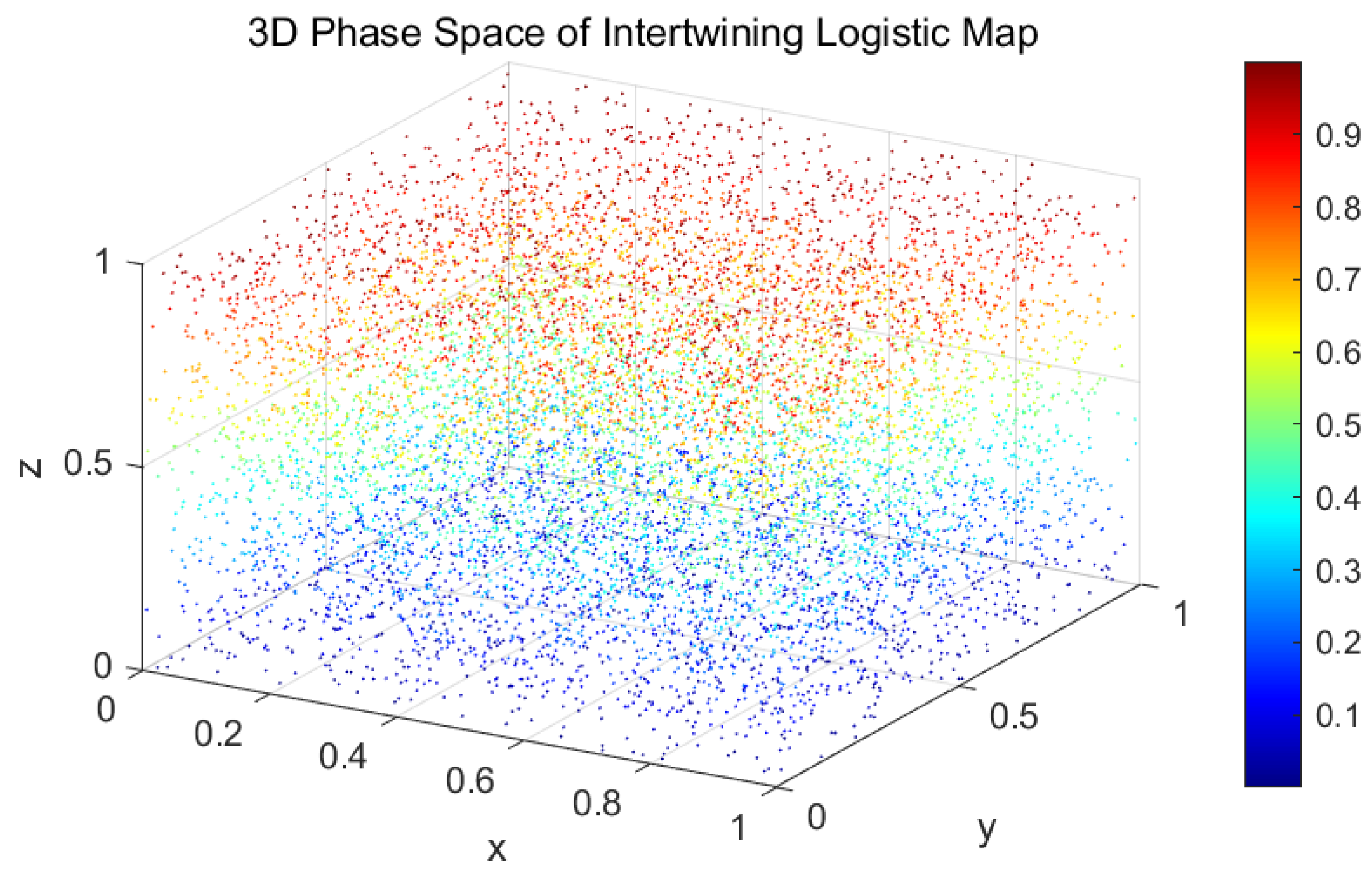
Figure 1 and Figure 2 depict the phase-space attractor with the initial conditions x(1) = 0.5142, y(1) = 0.0730, z(1) = 0.2475 and system parameters .
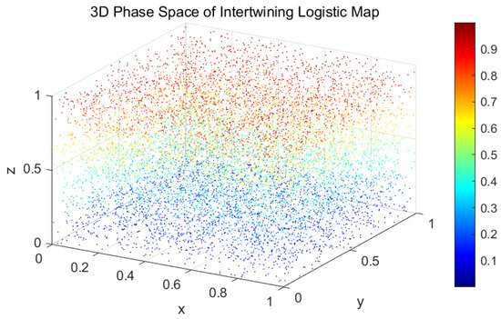
Figure 1.
Three-dimensional phase diagram.
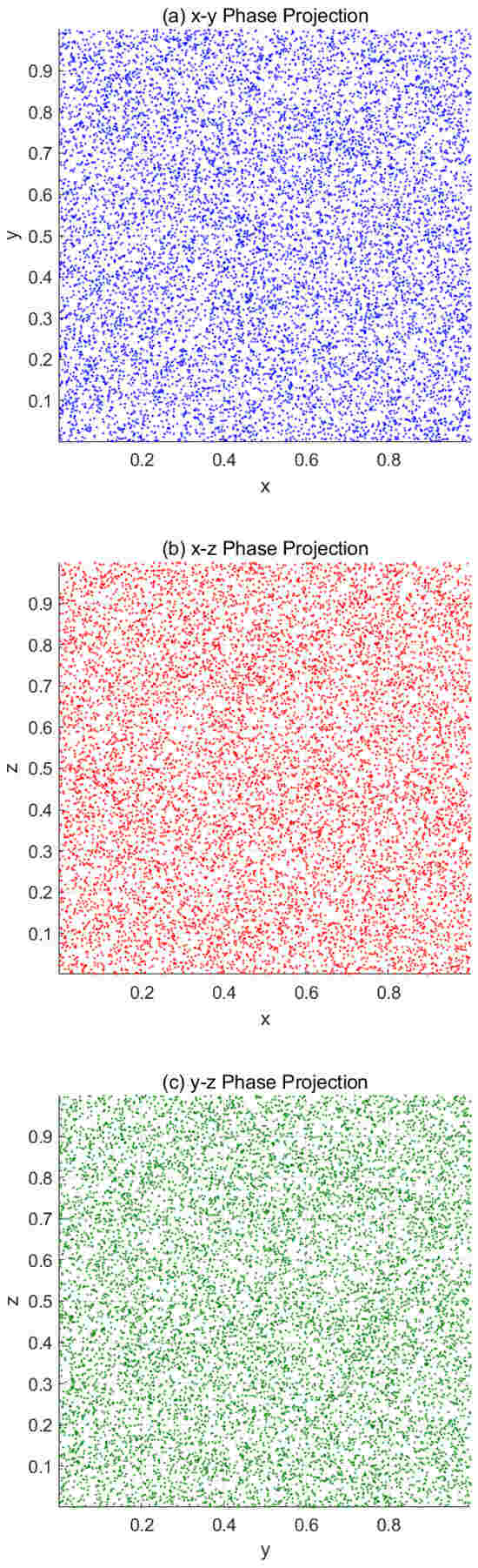
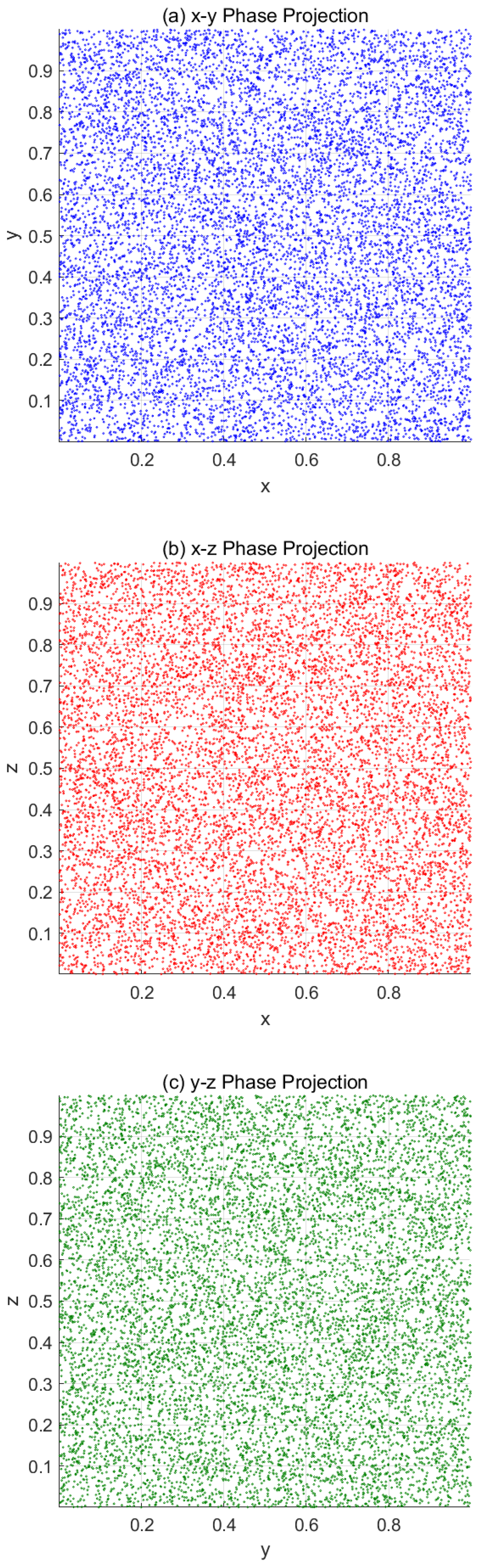
Figure 2.
Phase diagram. (a) x–y projection. (b) x–z projection. (c) y–z projection.
3.3.2. Bifurcation Diagram of Our Scheme
Figure 3 demonstrates the bifurcation characteristics under parametric control , and also uses x(1) = 0.5142, y(1) = 0.0730, z(1) = 0.2475 as the initial conditions.
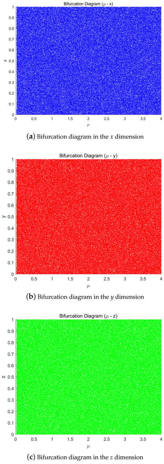
Figure 3.
Bifurcation diagrams of the chaotic system in different dimensions. (a) x-dimension. (b) y-dimension. (c) z-dimension.
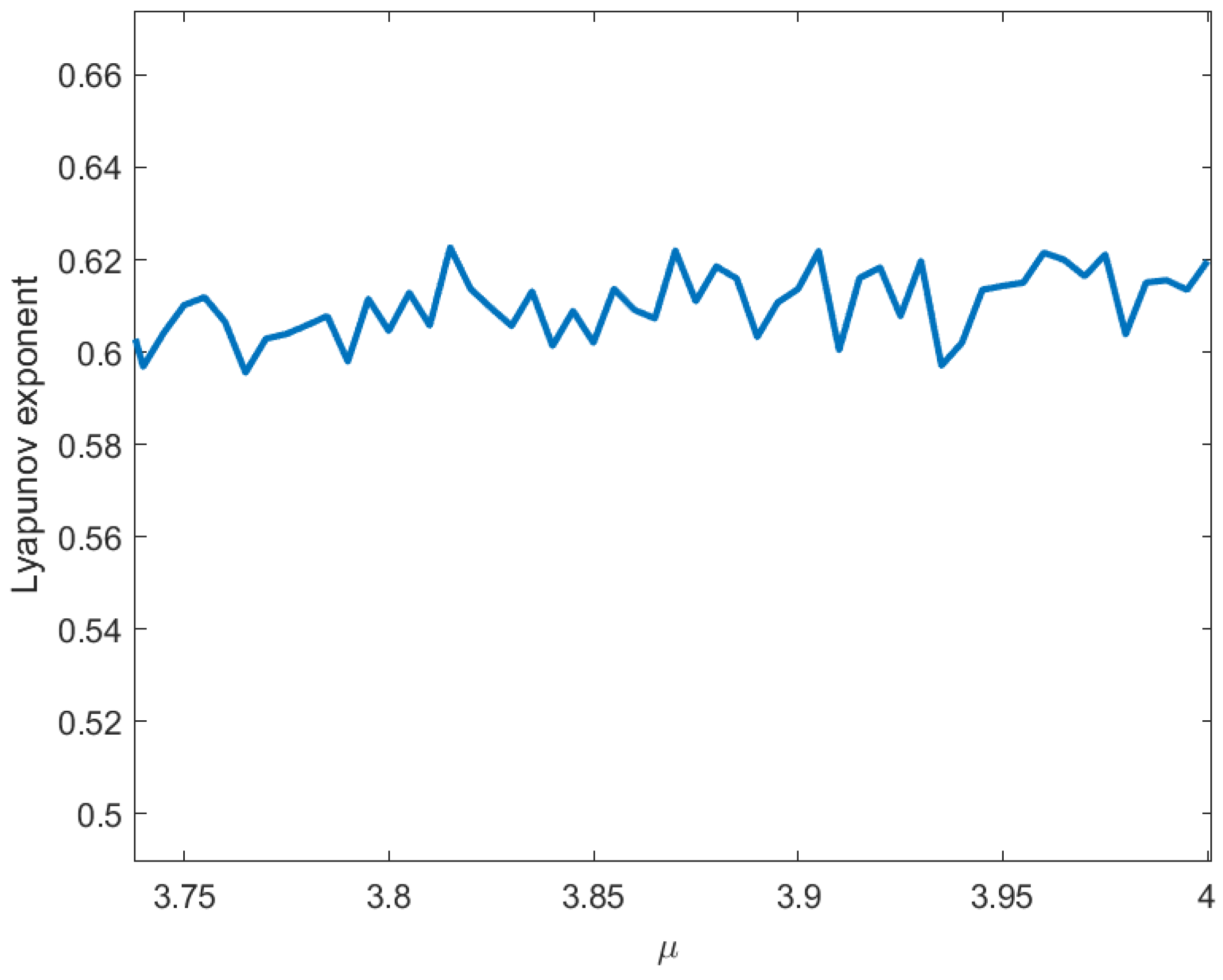
3.3.3. Lyapunov Exponents of Our Scheme
The defining feature of chaotic systems lies in their extreme sensitivity to initial values. The Lyapunov exponent (LE), as a key quantitative metric in dynamical systems research, precisely measures this sensitivity to initial conditions and serves as a crucial criterion for identifying chaotic phenomena. It quantifies the average exponential rate of convergence or divergence between adjacent trajectories in phase space:
- A positive LE value indicates the exponential divergence of neighboring trajectories, signifying the emergence of chaotic behavior;
- A negative LE value corresponds to the gradual convergence of trajectories, reflecting stable dynamical behavior governed by predictable attractors.
Figure 4 presents the variation in the Lyapunov exponent for the intertwining logistic map with respect to the control parameter . As can be seen from Figure 4, the Lyapunov exponents of the intertwining logistic map are all positive, indicating that the sequences generated by the map possess sufficient randomness.
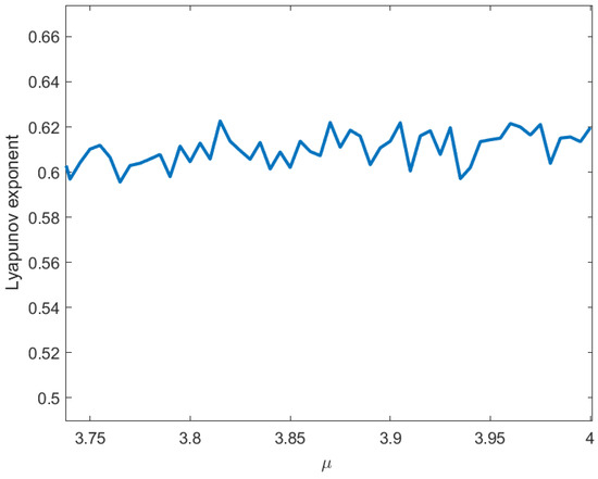
Figure 4.
Lyapunov exponent.
4. Proposed Scheme
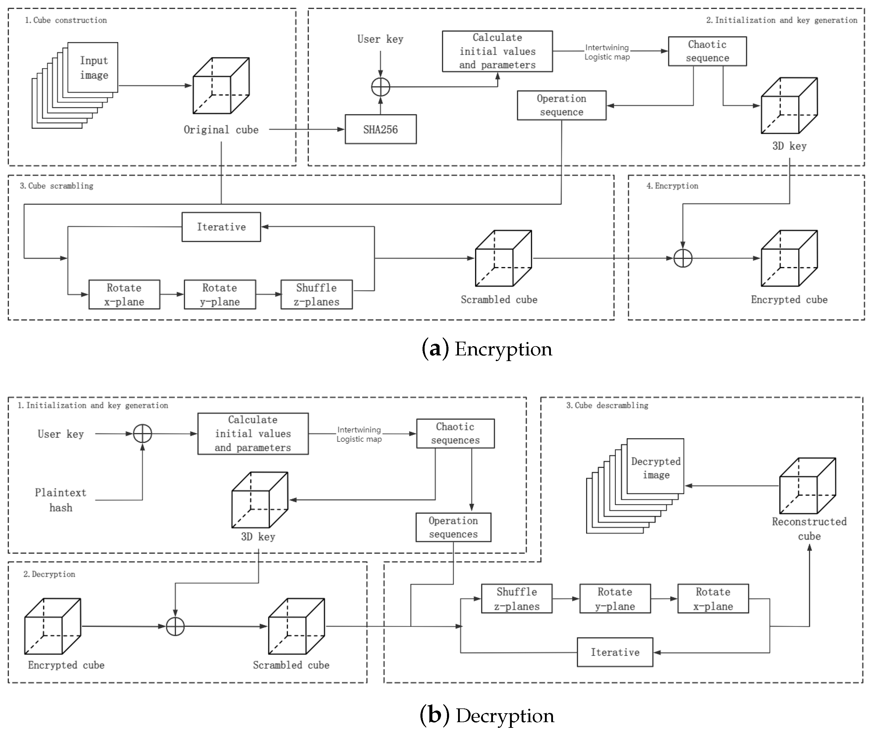
With the necessary preliminaries established, we are now ready to introduce our proposed Rubik’s Cube–poker model for image scrambling; the encryption and decryption schemes based on this model are given, and the non-standard case is analyzed. As shown in Figure 5, the encryption algorithm can be divided into four steps:
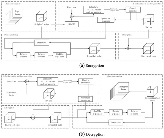
Figure 5.
A flow chart of our scheme.
- Cube construction , where is the set of input images, and is the original cube.
- Initialization and key generation , where K is the user key, A,B,C are the operation sequences, and is the 3D key.
- Cube scrambling , where is the scrambled cube.
- Encryption , where is the encrypted cube.
As a symmetric encryption, the steps of the decryption algorithm are as follows:
- Initialization and key generation , where h is the hash value of .
- Decryption , where is the decrypted cube.
- Cube descrambling , where is the descrambled cube.
4.1. Cube Construction
We can divide the multiple 2D plain images into blocks and stack the blocks to generate a 3D cube. Based on the size and number of the input 2D images, any size of 3D cube can be selected. Some examples of the relationships between the quantity and size of input images and cubes are shown in Table 1. Our scheme also provides solutions for non-standard cases where the input image cannot easily construct a cube. These will be discussed later.

Table 1.
Examples of 3D cubes generated from 2D images.
4.2. Initialization and Key Generation
The SHA function and an interleaved logistic map were used to generate the operation sequence and 3D key for the constructed 3D cube. The specific steps were as follows:
- Choose a set of 256-bit binary numbers as the user key.
- Calculate SHA256 on the 3D cube (the result is h), and XOR it with the user key to generate a binary number of length 256 for generating chaotic maps:
- Every eight bits of the binary number generated in Step 2 is converted into a decimal number, and a decimal array H of length 32 is generated. The parameters of the interleaved logistic map are calculated according to the following formula:
- Compute the initial values of the chaotic map:
- The parameters and initial values are input into the interleaved logistic map, and the chaotic sequences x, y, z are obtained by performing an iterative calculation. Then, the first 100 data of x, y, z are discarded to eliminate the transient effect.
- Sequences u, v, w are generated from the chaotic sequences x, y, z:where means that all values of sequence x are sorted in ascending order and output as sequence p, and the index at the corresponding position in is output as sequence q. ∼ means that the current value does not need to be output.
- Calculate the operation sequences based on u, v, w:
- Based on the modulo operation, the chaotic sequences x, y, z are converted into a 3D key as follows:where is the total number of times that the nested loop has been looped, and represent the number of times that the cube has been looped in the and z axis directions, respectively.
4.3. Cube Scrambling: Rubik’s Cube–Poker Model
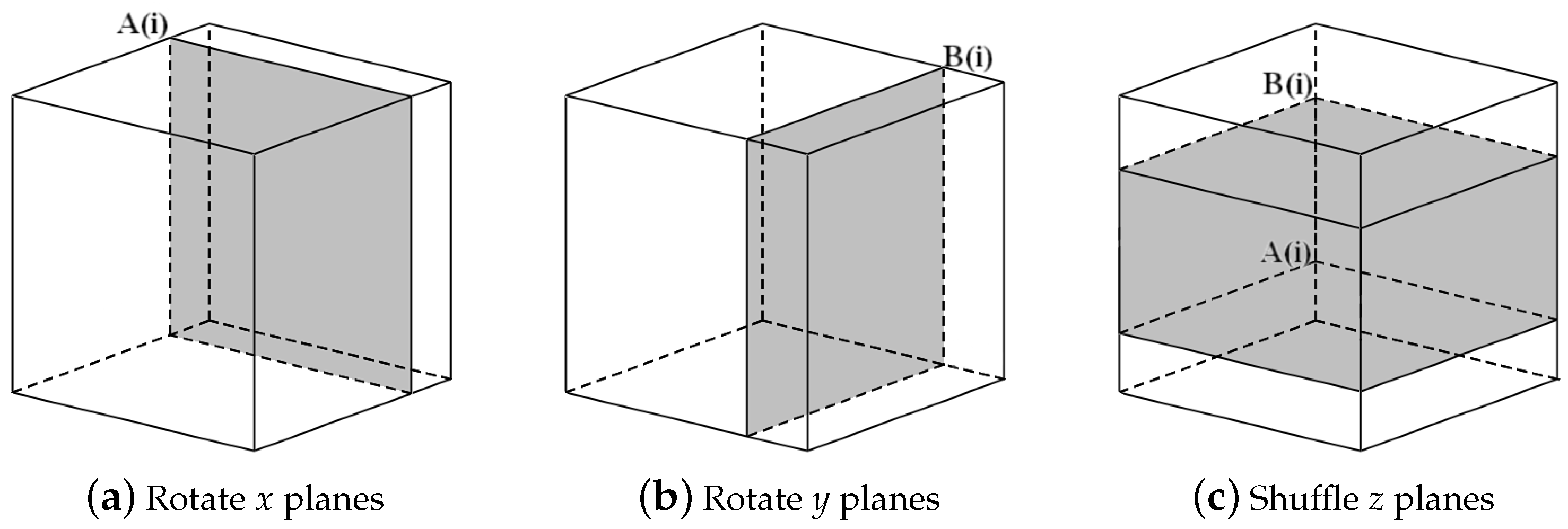
We propose a 3D scrambling method combining the benefits of the Rubik’s Cube rotation model and poker shuffle model. In the three-dimensional coordinate system, we define the set of all pixels with the same x coordinates as an x plane, the set of all pixels with the same y coordinates as a y plane, and the set of all pixels with the same z coordinates as a z plane. As shown in Figure 6, in one single round of iteration, one operation of rotation on an x plane, one operation of rotation on a y plane, and one operation of shuffle on z planes are carried out to sufficiently scramble the pixels. The scrambling process is as follows:
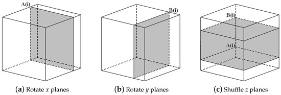
Figure 6.
Rubik’s Cube–poker model for image scrambling.
- Input three operation sequences, A, B and C, where A and B are in the range , and C is in the range . Define the total number of iterations K such that K is an integer multiple of i. In the ith iteration, carry out the following:
- Rotate the th x plane of the cube, as shown in Figure 6a. If , rotate the plane 90 degrees; if , rotate the plane 180 degrees; and if , rotate the plane 270 degrees.
- Rotate the th y plane of the cube, as shown in Figure 6b. If , rotate the plane 90 degrees; if , rotate the plane 180 degrees; and if , rotate the plane 270 degrees.
- As shown in Figure 7a, denote all of the z planes in the range as pile 2, all the z planes in the range as pile 1, and all the z planes in the range as pile 3, where , . If , pull pile 2 out and put it on top, as shown in Figure 7b; if , pull pile 2 out and put it at the bottom, as shown in Figure 7c; and if , swap pile 1 and pile 3, as shown in Figure 7d.
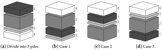 Figure 7. Encryption z plane shuffle.
4.4. Encryption
The scheme adopts a sequence cipher symmetric encryption system, where a 3D key sequence of the same length as the original cube is generated from the user key, and encryption is achieved through bitwise XOR operation between the 3D key and the scrambled cube:
where refers to the cube after it has been scrambled.
4.5. Decryption
Given that the encryption process is symmetric, the decryption procedure only requires the application of the decryption step followed by inverse scrambling. Initially, the 3D key and the operation sequence are reconstructed from the hash value of the original cube, following the same procedure as described in the Initialization and Key Generation phase.
The scrambled cube before encryption can be obtained by applying an XOR operation between the encrypted cube and the 3D key.
where refers to the cube after it has been scrambled.
4.6. Cube Descrambling
- Input three operation sequences, A, B, and C, where A and B are in the range , and C is in the range . Define the total number of iterations K such that K is an integer multiple of i. During the ith iteration, calculate :
- If , divide the array into three piles. Denote all the z planes in the range as pile 1, all the z planes in the range as pile 2, and all the z planes in the range as pile 3, where , . If , denote all the z planes in the range as pile 1, all the z planes in the range as pile 2, and all the z planes in the range as pile 3. If , denote all the z planes in the range as pile 1, all the z planes in the range as pile 2, and all the z planes in the range as pile 3.
- Rearrange the array in the order of pile 1, pile 2, and pile 3 from top to bottom to restore the original sequence.
- Rotate the th y plane of the cube. If , rotate the plane 270 degrees; if , rotate the plane 180 degrees; and if , rotate the plane 90 degrees.
- Rotate the th x plane of the cube. If , rotate the plane 270 degrees; if , rotate the plane 180 degrees; and if , rotate the plane 90 degrees.
4.7. The General Case
Considering the general case, for a situation in which it is difficult to construct a cube, an cuboid can be constructed.
- If , consider building a cuboid with smaller N.
- If , perform the zero-filling operation, and carry out the original encryption scheme.
- If , as shown in Figure 8, the original encryption process of x and y plane rotation is only carried out on the pixels of the z planes. When shuffling the z plane, the bottom part is firstly placed at the top, and the gray part is rearranged according to the original scheme and placed at the top of the white part.
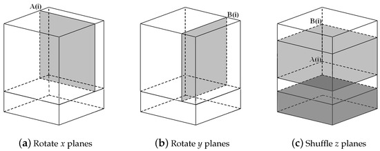 Figure 8. General case.
5. Simulation and Analysis of the Proposed Scheme
To evaluate the efficiency, correctness, security, and robustness of the proposed image encryption scheme, simulations were conducted using MATLAB 2019a on a personal computer equipped with an Intel Core i7-9700 processor (3.00 GHz) and 16 GB RAM, running Windows 10 64-bit. The test images were selected from the USC-SIPI image database, including both grayscale and RGB images.
5.1. Key Space
The key space refers to the size and range of all possible values of the key. A sufficiently large key space makes brute-force attacks difficult for attackers, preventing them from easily guessing the correct key through exhaustive search. For image encryption, the minimum required key space is .
In the proposed scheme, the secure key set consists of user-defined keys and the parameters and initial values of the intertwining logistic map. The user key is 256 bits long, allowing for different possible values. On a 64-bit computer, the parameters and initial values of the intertwining logistic map can take different combinations. Therefore, the total key space of this scheme is . This means that a brute-force attack would require at most computations.
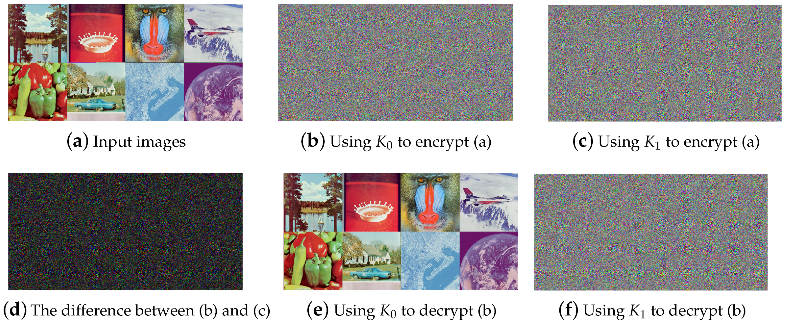
5.2. Key Sensitivity Analysis
We choose
represented in hexadecimal, as the user key and make tiny changes to obtain
We encrypt the input images shown in Figure 9a using , , , and , respectively. The differences between the 3D keys and the resulting encrypted cubes are presented in Table 2, and some images are shown in Figure 9.
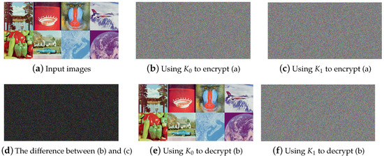
Figure 9.
Encryption and decryption images under different keys.
Table 2.
Difference analysis.
5.3. Plaintext Attack
In order to test the plaintext sensitivity of the proposed scheme, the following are defined:
- (1)
- : A set of images consisting of eight grayscale images;
- (2)
- : A set of eight RGB images shown in Figure 9a;
- (3)
- : A set of pure black images with all pixel values being 0;
- (4)
- A set of pure white images with all pixel values being 255.
We construct plaintext cubes of using the above image sets, modify the pixel values at each cube , and encrypt the cubes before and after the modification. We calculate the NPCR, UACI of encrypted cubes, as shown in Table 2.
5.3.1. Histogram Analysis
To resist statistical attacks, the histogram of the encrypted image must be uniform and completely different from that of the plaintext image. The histograms of a plaintext image are shown on the top row in Figure 10 and those of an encrypted image are shown on the bottom row. It can be observed that the histograms of the three channels in the plaintext cube are non-uniform, whereas those of the encrypted cube are uniform and exhibit a marked difference from the plaintext histograms. The test results and entropy are shown in Table 3.
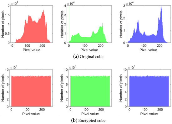
Figure 10.
RGB channel histogram.
Table 3.
test and entropy under different keys.
5.3.2. Correlation Analysis
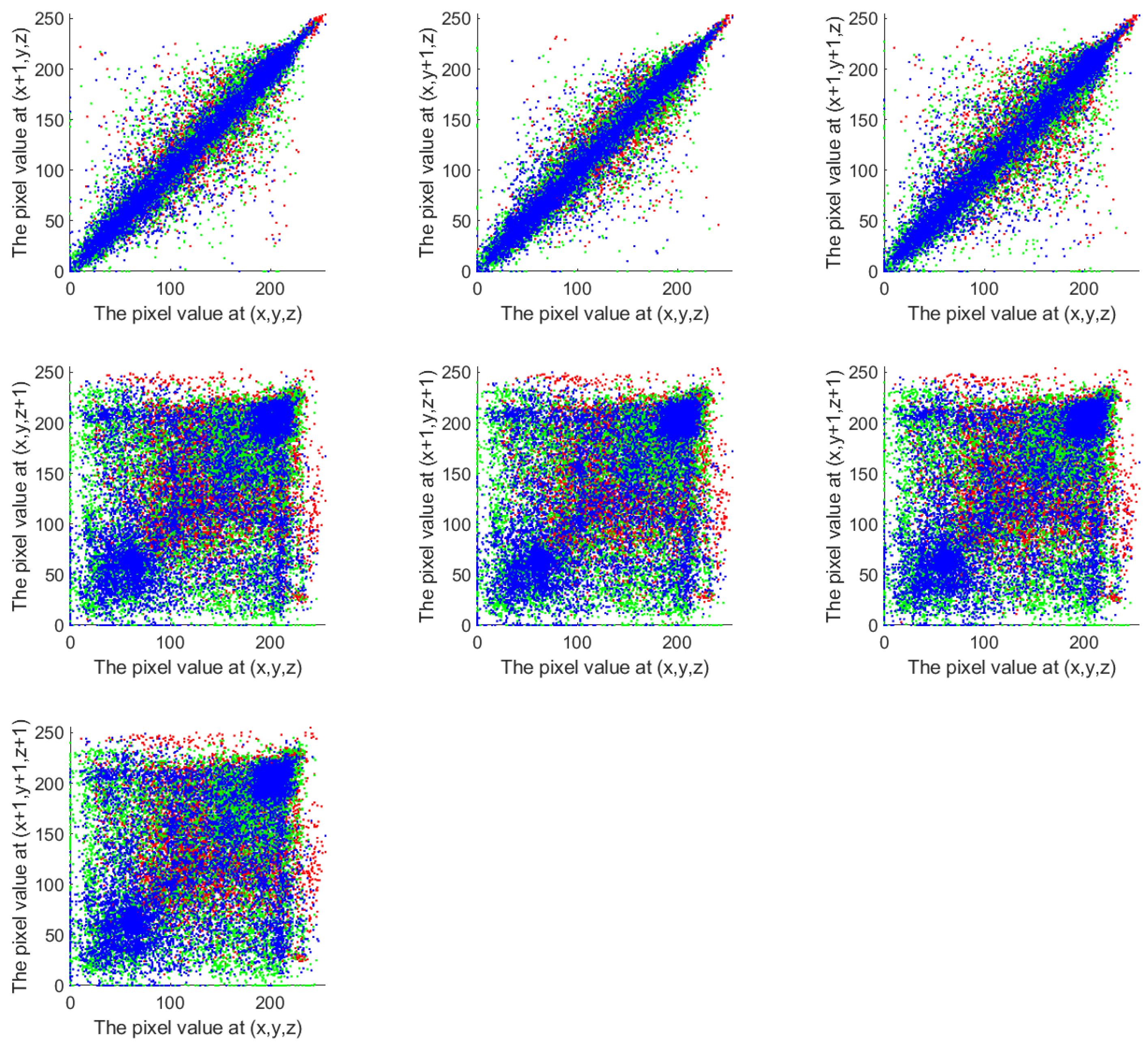
A correlation analysis reflects the algorithm’s scrambling impact. In order to prevent statistical attacks, the strong connections must be broken. To analyze the correlation between adjacent pixels in this scheme, 10,000 pixels were randomly selected from both the original plaintext cube and the encrypted cube. For each selected pixel, its adjacent pixels were identified along seven directions: x, y, z, , , , and . Correlation analysis scatter plots were drawn using the pixel values of each pair as the horizontal and vertical coordinates, as shown in Figure 11 and Figure 12. The corresponding correlation coefficients are listed in Table 4.
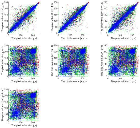
Figure 11.
Correlation of original cube.

Figure 12.
Correlation of encrypted cube.
Table 4.
The correlation coefficient.
It can be observed that the original plaintext cube exhibits strong correlations along the x, y, and directions, while the correlations in the other four directions are slightly weaker. In contrast, the encrypted cube generated by the proposed scheme shows weak correlations in all seven directions. This indicates that the scheme effectively disrupts the correlation between adjacent pixels, demonstrating strong diffusion capability and resistance to statistical analysis attacks.
5.4. Robust Analysis
5.4.1. Occlusion
We deleted 25% and 50% of the encrypted cube to simulate an occlusion attack, as shown in Figure 13a. We treated all of the missing data as zeros. The decrypted images using our scheme are as shown in Figure 13b, and the decrypted images using scheme [31] are shown in Figure 13c. The quality analysis of the reconstructed images is shown in Table 5.
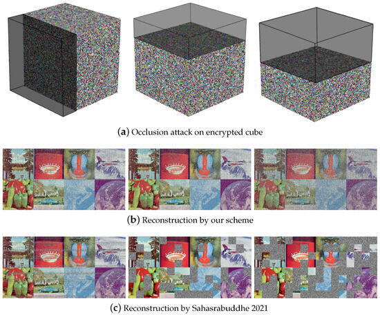
Figure 13.
Data loss attack [31].
Table 5.
Reconstructed image quality analysis.
Through comparative experiments and observations, the proposed scheme achieves more thorough pixel scrambling, thus possessing better data loss recovery capabilities. The reconstructed image can visually recognize the information contained in the input image. The scheme proposed by Sahasrabuddhe et al. uses a simple permutation operation to scramble image pixels [31]. Although the time complexity is lower and the execution efficiency is higher, the pixel scrambling is not thorough enough, as shown in Figure 13c. Although the part without lost data perfectly restores the entire content of the plaintext image, the part that suffers from data loss cannot be recovered at all, so it has the risk of losing key information. In comparison, our scheme scrambles pixels more thoroughly and has a better ability to recover from data loss.
5.4.2. Noise Attack
Encrypted images may experience noise disturbance when transmitted over unsecure channels. A good encryption scheme should have some tolerance for noise attacks. Gaussian noise, Poisson noise, and speckle noise were added to the encrypted cube, and the decrypted image is shown in Figure 14.
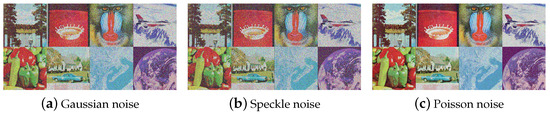
Figure 14.
Noise attack.
5.5. Execution Speed
Table 6 provides comparison results with some existing encryption schemes in terms of execution time. It can be observed that our proposed scheme outperforms many existing multi-image encryption schemes in terms of time cost, and the color space of the input image can be either grayscale or RGB. Combined with the data loss analysis in the previous section, this scheme can achieve a good balance between encryption effect and efficiency, and can quickly and efficiently encrypt a large number of images.
Table 6.
Execution speed for encryption of multiple images.
5.6. NIST Test
The National Institute of Standards and Technology Special Publication 80022 (NIST SP 800-22) provides a cryptographic-grade validation tool, employing 15 statistically rigorous methods to quantify the randomness of sequences. The p-value is the key indicator of statistical randomness compliance. A p-value exceeding the significance threshold (p-value > 0.01) demonstrates that the sequence under analysis exhibits no statistically significant deviation from a random distribution within the framework of the specified statistical test. The three chaotic sequences generated by the intertwining logistic map for 3D cryptographic key construction were formatted to comply with the NIST SP 800-22 test suite specifications. As shown in Table 7, all three chaotic sequences successfully passed 15 statistical tests within the NIST suite. The chaotic sequences generated by our scheme exhibit high randomness, providing a secure foundation for subsequent key generation and significantly enhancing the security of the encryption system.
Table 7.
NIST randomness test of generated chaotic x y z sequence.
6. Conclusions
This paper proposes a new Rubik’s Cube–poker model for image scrambling and proposes a 3D multi-image encryption scheme based on the model. The scheme achieves a better balance between time efficiency and scrambling performance. Simulations and analyses show that it has high key sensitivity, low correlation, and robustness, and can effectively resist histogram analyses, occlusion attacks, noise attacks, differential attacks, etc. Compared with other multi-image encryption methods, this scheme has sufficient scrambling, a low time cost, and a low requirement for input images. Moreover, it has a strong ability to recover from data loss.
Although the proposed scheme strikes a good balance between encryption performance and efficiency, there are several areas that could benefit from further improvement in future research:
- While the Rubik’s Cube–poker model effectively shuffles a substantial portion of pixels, it does not guarantee full-range pixel perturbation in a single iteration. The scrambling model could be further optimized to involve a larger number of pixels in each iteration, enhancing the scrambling effect and improving overall encryption security.
- Although more efficient than many existing approaches, the scheme may still require further optimization to become suitable for large-scale applications. The encryption process can be streamlined to reduce computational time while maintaining robustness and security, aiming to improve its practicality for real-time or large-scale use cases.
- The current analysis primarily addresses occlusion and noise attacks. However, more advanced attack evaluations, such as known-plaintext attacks or chosen-ciphertext attacks, have not yet been explored. Expanding the evaluation to include these attack models would provide a more comprehensive understanding of the scheme’s security.
Author Contributions
R.F.: formal analysis, writing—original draft preparation. J.Z.: conceptualization, project administration, writing—review and editing. C.L.: data curation, writing—original draft preparation. All authors have read and agreed to the published version of the manuscript.
Funding
This work was funded by the Taishan Scholars Program (No. tsqn202306315).
Data Availability Statement
The datasets generated and analyzed during the current study are available from the corresponding author on reasonable request.
Conflicts of Interest
The authors declare no conflicts of interest. The funders had no role in the design of the study; in the collection, analyses, or interpretation of the data; in the writing of the manuscript; or in the decision to publish the results.
References
- Hamid, N.; Yahya, A.; Ahmad, R.B.; Al-Qershi, O.M. Image steganography techniques: An overview. Int. J. Comput. Sci. Secur. 2012, 6, 168–187. [Google Scholar]
- Altaay, A.A.J.; Sahib, S.B.; Zamani, M. An introduction to image steganography techniques. In Proceedings of the 2012 International Conference on Advanced Computer Science Applications and Technologies (ACSAT), Kuala Lumpur, Malaysia, 26–28 November 2012; pp. 122–126. [Google Scholar]
- Hussain, M.; Hussain, M. A survey of image steganography techniques. Int. J. Adv. Sci. Technol. 2013, 54, 113–124. [Google Scholar]
- Kaur, S.; Bansal, S.; Bansal, R.K. Steganography and classification of image steganography techniques. In Proceedings of the 2014 International Conference on Computing for Sustainable Global Development (INDIACom), New Delhi, India, 5–7 March 2014; pp. 870–875. [Google Scholar] [CrossRef]
- Yahya, A.; Yahya, A. Steganography techniques. In Steganography Techniques for Digital Images; Springer: Cham, Switzerland, 2019; pp. 9–42. [Google Scholar]
- Potdar, V.M.; Han, S.; Chang, E. A survey of digital image watermarking techniques. In Proceedings of the INDIN’05. 2005 3rd IEEE International Conference on Industrial Informatics, Perth, Australia, 3–5 August 2005; pp. 709–716. [Google Scholar]
- Chandrakar, N.; Bagga, J. Performance comparison of digital Image watermarking techniques: A survey. Int. J. Comput. Appl. Technol. Res. 2013, 2, 126–130. [Google Scholar] [CrossRef]
- Dixit, A.; Dixit, R. A review on digital image watermarking techniques. Int. J. Image, Graph. Signal Process. 2017, 9, 56. [Google Scholar] [CrossRef]
- Begum, M.; Uddin, M.S. Digital image watermarking techniques: A review. Information 2020, 11, 110. [Google Scholar] [CrossRef]
- Kumar, M.; Saxena, A.; Vuppala, S.S. A.; Vuppala, S.S. A survey on chaos based image encryption techniques. In Multimedia Security Using Chaotic Maps: Principles and Methodologies; Springer: Cham, Switzerland, 2020; pp. 1–26. [Google Scholar]
- Kumar, M.; Lahcen, R.A.M.; Mohapatra, R.; Alwala, C.; Kurella, S.V.K. Review of image encryption techniques. J. Comput. Eng. 2020, 14, 31–37. [Google Scholar] [CrossRef]
- Kaur, M.; Kumar, V. A comprehensive review on image encryption techniques. Arch. Comput. Methods Eng. 2020, 27, 15–43. [Google Scholar] [CrossRef]
- Bourbakis, N.; Alexopoulos, C. Picture data encryption using scan patterns. Pattern Recognit. 1992, 25, 567–581. [Google Scholar] [CrossRef]
- Fridrich, J. Symmetric ciphers based on two-dimensional chaotic maps. Int. J. Bifurc. Chaos Appl. Sci. Eng. 1998, 8, 1259–1284. [Google Scholar] [CrossRef]
- Chen, G.; Mao, Y.; Chui, C.K. A symmetric image encryption scheme based on 3D chaotic cat maps. Chaos Solitons Fractals 2004, 21, 749–761. [Google Scholar] [CrossRef]
- Pareek, N.; Patidar, V.; Sud, K. Image encryption using chaotic logistic map. Image Vis. Comput. 2006, 24, 926–934. [Google Scholar] [CrossRef]
- Gao, T.; Chen, Z. A new image encryption algorithm based on hyper-chaos. Phys. Lett. A 2008, 372, 394–400. [Google Scholar] [CrossRef]
- Behnia, S.; Akhshani, A.; Mahmodi, H.; Akhavan, A. A novel algorithm for image encryption based on mixture of chaotic maps. Chaos Solitons Fractals 2008, 35, 408–419. [Google Scholar] [CrossRef]
- Wu, Y.; Yang, G.; Jin, H.; Noonan, J.P. Image encryption using the two-dimensional logistic chaotic map. J. Electron. Imaging 2012, 21, 013014. [Google Scholar] [CrossRef]
- Wang, X.Y.; Zhang, Y.Q.; Bao, X.M. A novel chaotic image encryption scheme using DNA sequence operations. Opt. Lasers Eng. 2015, 73, 53–61. [Google Scholar] [CrossRef]
- Pak, C.; Huang, L. A new color image encryption using combination of the 1D chaotic map. Signal Process. 2017, 138, 129–137. [Google Scholar] [CrossRef]
- Xian, Y.; Wang, X. Fractal sorting matrix and its application on chaotic image encryption. Inf. Sci. 2021, 547, 1154–1169. [Google Scholar] [CrossRef]
- Bao, L.; Zhou, Y. Image encryption: Generating visually meaningful encrypted images. Inf. Sci. 2015, 324, 197–207. [Google Scholar] [CrossRef]
- Chen, J.; Wu, Y.; Sun, Y.; Yang, C. Image Encryption Algorithm Using 2-Order Bit Compass Coding and Chaotic Mapping. Symmetry 2022, 14, 1482. [Google Scholar] [CrossRef]
- Çelik, H.; Doğan, N. A hybrid color image encryption method based on extended logistic map. Multimed. Tools Appl. 2024, 83, 12627–12650. [Google Scholar] [CrossRef]
- Tang, Z.; Song, J.; Zhang, X.; Sun, R. Multiple-image encryption with bit-plane decomposition and chaotic maps. Opt. Lasers Eng. 2016, 80, 1–11. [Google Scholar] [CrossRef]
- Zhang, X.; Wang, X. Multiple-image encryption algorithm based on mixed image element and permutation. Opt. Lasers Eng. 2017, 92, 6–16. [Google Scholar] [CrossRef]
- Zhang, X.; Wang, X. Multiple-image encryption algorithm based on DNA encoding and chaotic system. Multimed. Tools Appl. 2019, 78, 7841–7869. [Google Scholar] [CrossRef]
- Hanif, M.; Naqvi, R.A.; Abbas, S.; Khan, M.A.; Iqbal, N. A novel and efficient 3D multiple images encryption scheme based on chaotic systems and swapping operations. IEEE Access 2020, 8, 123536–123555. [Google Scholar] [CrossRef]
- Patro, K.A.K.; Acharya, B. A novel multi-dimensional multiple image encryption technique. Multimed. Tools Appl. 2020, 79, 12959–12994. [Google Scholar] [CrossRef]
- Sahasrabuddhe, A.; Laiphrakpam, D.S. Multiple images encryption based on 3D scrambling and hyper-chaotic system. Inf. Sci. 2021, 550, 252–267. [Google Scholar] [CrossRef]
- Gao, X.; Mou, J.; Banerjee, S.; Cao, Y.; Xiong, L.; Chen, X. An effective multiple-image encryption algorithm based on 3D cube and hyperchaotic map. J. King Saud Univ. Comput. Inf. Sci. 2022, 34, 1535–1551. [Google Scholar] [CrossRef]
- Zhang, X.; Wang, X. Multiple-Image Encryption Algorithm Based on 3D Permutation Model and Chaotic System. Symmetry 2018, 10, 660. [Google Scholar] [CrossRef]
- Li, L. A novel chaotic map application in image encryption algorithm. Expert Syst. Appl. 2024, 252, 124316. [Google Scholar] [CrossRef]
- Ponnambalam, M.; Ponnambalam, M.; Jamal, S.S. A robust color image encryption scheme with complex whirl wind spiral chaotic system and quadrant-wise pixel permutation. Phys. Scr. 2024, 99, 105239. [Google Scholar] [CrossRef]
- Mathivanan, P.; Maran, P. Color image encryption based on novel kolam scrambling and modified 2D logistic cascade map (2D LCM). J. Supercomput. 2024, 80, 2164–2195. [Google Scholar] [CrossRef]
- Shatheesh Sam, I.; Devaraj, P.; Bhuvaneswaran, R. An intertwining chaotic maps based image encryption scheme. Nonlinear Dyn. 2012, 69, 1995–2007. [Google Scholar] [CrossRef]
- Loukhaoukha, K.; Chouinard, J.Y.; Berdai, A. A secure image encryption algorithm based on Rubik’s cube principle. J. Electr. Comput. Eng. 2012, 2012, 7. [Google Scholar] [CrossRef]
- Zhu, H.; Dai, L.; Liu, Y.; Wu, L. A three-dimensional bit-level image encryption algorithm with Rubik’s cube method. Math. Comput. Simul. 2021, 185, 754–770. [Google Scholar] [CrossRef]
- Nair, A.; Dalal, D.; Mangrulkar, R. Colour image encryption algorithm using rubik’s cube scrambling with bitmap shuffling and frame rotation. Cyber Secur. Appl. 2024, 2, 100030. [Google Scholar] [CrossRef]


Disclaimer/Publisher’s Note: The statements, opinions and data contained in all publications are solely those of the individual author(s) and contributor(s) and not of MDPI and/or the editor(s). MDPI and/or the editor(s) disclaim responsibility for any injury to people or property resulting from any ideas, methods, instructions or products referred to in the content. |
© 2025 by the authors. Licensee MDPI, Basel, Switzerland. This article is an open access article distributed under the terms and conditions of the Creative Commons Attribution (CC BY) license (https://creativecommons.org/licenses/by/4.0/).