Article

Pore Structure Alteration of Shale with Exposure to Different Fluids: The Longmaxi Formation Shale in the Sichuan Basin, China

1
School of Resources & Environment and Safety Engineering, University of South China, Hengyang 421001, China
2
State Key Laboratory of Coal Mine Disaster Dynamics and Control, Chongqing University, Chongqing 400030, China
3
College of Civil Engineering, Xiangtan University, Xiangtan 411105, China
4
State Key Laboratory of Safety and Health for Metal Mines, Maanshan 243000, China
5
CCFEB Civil Engineering Co., Ltd., Changsha 410004, China
*
Author to whom correspondence should be addressed.
Minerals 2023, 13(11), 1387; https://doi.org/10.3390/min13111387
Submission received: 6 September 2023 / Revised: 17 October 2023 / Accepted: 25 October 2023 / Published: 30 October 2023

Abstract

:
The interaction between shale and various fluids is crucial as it modifies pore structures, which govern the effective development of shale gas and the geological storage of carbon dioxide in shale formations. In this study, samples from the Longmaxi Formation shale in Sichuan Basin of China were exposed to different fluids, including 6 MPa CO2, 12 MPa CO2, 6 MPa CO2+brine, and 12 MPa CO2+brine, at 45 °C for 100 days. Various methods, including X-ray diffraction (XRD), X-ray fluorescence (XRF), field-emission scanning electron microscopy (FESEM), and the low-pressure gas adsorption (N2) test, were adopted to evaluate chemical and structural changes during the exposure process. After being treated with supercritical CO2+brine and subcritical CO2+brine, the shale underwent significant changes in its major element composition. The content of Ca, Al, and K in shale saturated with supercritical CO2+brine decreased from 13.00% to 10.34%, from 3.65% to 3.36%, and from 1.56% to 1.37%, respectively. Meanwhile, the content of Si and Na in the same shale increased slightly after saturation. The amount of quartz and dolomite increased, while the levels of clay and calcite slightly decreased. The surface of the shale sample became rougher and small bumps and cracks appeared after saturation with different fluids, as shown by the FESEM analysis results. Furthermore, the changes in both the total pore volume and pore size followed a similar pattern to the alterations in the specific surface areas. The highest level of variation occurred with the shale that was saturated with 12 MPa of CO2, indicating that gas pressure and CO2 phase state have a significant influence on the shale’s pore structure. In addition, the distribution of pore sizes showed a bias towards larger sizes across all diameters; this suggests that the reaction resulted in a decrease in the number of micropores. This also highlights that the impact of varying fluid saturation was primarily focused on micropores and macropores. The results of this study provided experimental evidence to further test the mechanisms and permeability of geological storage of CO2 in organic-rich self-sourced shale.

1. Introduction

The successful large-scale commercial development of shale reservoirs in the US has altered the global petroleum supply and energy landscape, further triggering a boom in exploration and development for shale reservoirs around the world [1]. Shale gas is a crucial resource in China due to its abundance and potential. China’s shale gas industry has developed rapidly in the past decade and has achieved consistent oil and gas production. It is estimated that the global recoverable shale gas resources come to approximately 2.07 × 10¹⁴ m3, accounting for 32% of the world’s total natural gas resources [2]. Meanwhile, shale has a stronger affinity for CO2 than CH4 [3]; thus, injecting CO2 into organic-rich gas shale not only allows the possibility of storing billions of tons of CO2 in shale formations, but also enhances gas recovery, which is beneficial for achieving CO2 source–sink matching and reduces the entire cost for CO2 sequestration [4]. In addition, the microstructure of shale, composed of diagenetic minerals, organic matter, and a pore network, is a key factor in determining its gas storage capacity.
Carbon dioxide sequestration in shale gas reservoirs has been established as an effective method to reduce CO2 emissions and mitigate the greenhouse effect. Recently, shale gas reservoirs have attracted significant attention and have been widely investigated for their potential in CO2 geological storage and utilization. Though improvements have been achieved by many researchers, CO2 sequestration and enhanced gas recovery in shale formations are still in their preliminary stages [5]. It is difficult to accurately characterize the process of CO2 sequestration in shale because of its complex heterogeneous and anisotropic composition and pore structure, as well as the expensive equipment and experimental conditions required [6,7]. The CO2 injected into shale formations is trapped through a series of mechanisms including solubility, residual trapping, mobility trapping, and mineral trapping, while solubility trapping is the primary mechanism for rock mineral and pore structure alteration [8], affecting CO2 storage capacity and storage effects. Shale rocks have complex, multi-scale pore structures with pores ranging in size from nano- to micrometers, which are distributed in a disorderly and unsystematic manner [9,10]. According to the International Union of Pure and Applied Chemistry (IUPAC), these pores can be easily found within the shale matrix or organic matter. Pores with a diameter lower than 2 nm are classified as micropores, those with a diameter greater than 50 nm are classified as macropores, and those pores with a diameter between 2 and 50 nm are categorized as mesopores [11]. To effectively model the sequestration of CO2 in shale gas reservoirs, it is essential to determine pore volume (PV), pore size distribution (PSD), pore width (PW), and specific surface area (SSA). These pore parameters provide quantitative information on the pore structures. Additionally, these pore structures should be figured out in the geophysical, petrophysical, and geomechanical modeling of CO2 sequestration in shale gas reservoirs. The storage and fluid conductivity of shale depend highly on its pore structures. This becomes even more important for revealing storage mechanisms, enhanced shale gas recovery with CO2, and actual field operations [4,7,12].
When CO2 is injected into shale rock, it dissolves and alters the acid–base balance triggering mineral dissolution and precipitation [4]. As a result of the dissolution, new pores, fractures, and flow channels will be formed in shale, and the porosity and permeability will increase to some extent, while as a result of the precipitation, pores will collapse and the pore throat will be blocked [4]. The long-term exposure of shale to CO2 may lead to structural and chemical changes in shale that induce plume migration behavior and/or changes to the sealing efficiency of caprocks immediately above the sCO2 zone over a geological timescale. Furthermore, CO2 is an acidic and corrosive gas, and CO2 will most likely be at either a gaseous, supercritical, or subcritical phase state after being injected into a shale gas reservoir. To be more specific, the injected CO2 exists in a supercritical state because temperature and pressure surpass the critical value (critical temperature: 31.04 °C, critical pressure: 7.38 MPa) as the depth increases. While the properties of supercritical CO2 (ScCO2) are quite different from gaseous and subcritical-phase CO2 (SubCO2), ScCO2 has the characteristics of high diffusivity, low viscosity, and surface tension, and it can be used as the fracturing fluid in shale gas reservoir stimulation. It can easily penetrate into the matrix and pores of the shale to dissolve the nonpolar and weakly polar material in the shale. In addition, considering the existence of underground water in shale formations, the chemical reactions among water, CO2, and shale rock may be even more significant. Chemical reaction mechanisms in underground conditions can be impacted by the anions and cations present in groundwater [13]. Hence, it is important to understand how different fluids (6 MPa CO2, 12 MPa CO2, 6 MPa CO2+brine, 12 MPa CO2+brine) alter the pore structure of shale.
Compared with conventional reservoirs, shale formations are characterized by an abundant complex pore structure, which is strongly associated with the shale gas resource potential and production and CO2 storage capabilities and risks [10]. Given the significance of pore structure evaluations, plenty of methods have been used to analyze and characterize pore structures of shale, including direct and indirect methods. Direct methods such as atomic force microscopy (AFM), computed tomography scanning, scanning electron microscopy (SEM), etc., can directly observe the size, morphology, and type of pores in shale, while indirect methods such as the low-pressure gas adsorption method (LPGA), mercury intrusion porosimetry (MIP), small angle neutron scattering (SANS), ultrasmall angle neutron scattering (USANS), nuclear magnetic resonance (NMR), etc., probe the pore structure usually with the help of other media. Each of the techniques listed above has its strengths and limitations and can provide acceptable information, but does not provide specific information on the geometric details of the pore structure of shale. In order to measure pore structural changes as accurately as possible, these changes must be characterized using reliable and accurate void space descriptions. As commonly adopted methods, the gas adsorption methods and SEM belong to nondestructive and time-saving methods, which can detect pores smaller than 2 nm. In this regard, the LGAM and SEM methods are applied to characterize the pore structure of shale in this study.
Generally, CO2 can be injected into aquifers or old gas reservoirs as a way to sequester carbon, and can also be used to displace methane from shale [14]. It is self-explanatory that the pore structure of shale shows significant changes associated with exposure to different fluids [15,16]. Sanguinito et al. [17] exposed shale to dry CO2, and discovered that the SSA remained relatively stable, and the SSA and PV associated with micropores showed a substantial decrease and only small changes in the pore volume and size distribution of ultra-micropores. Lu et al. [18] reported the influencing mechanism of pore structure changes on mechanical properties, and showed that the proportion of micropores and mesopores decreased while the proportion of macropores increased after CO2 saturation. Furthermore, the effect of supercritical CO2 on the pore structure of shale is stronger than that of gaseous CO2—that is, the pore structure alteration is strongly related to the kind of fluid to which the shale is exposed. Li et al. [19] conducted a series of high-temperature and high-pressure immersion experiments to investigate the impacts of water/supercritical CO2–rock interaction on the micro-mechanical properties of shale, and experimental results showed that the aperture of induced fracture was smaller after soaking with supercritical CO2, and the induced fracture width increased with the increase in soaking pressure and temperature but was not sensitive to soaking time. Alafnan [20] revealed that CO2 interacted with kerogen, resulting in adsorption and swelling at supercritical conditions, and the effect of CO2 was more pronounced at higher pressure. Hazarika et al. [21] discussed the important factors of shale formation for CO2 gas storage, and pointed out that different types of clay minerals had excellent cation-exchange capacity, interlayer spacing, and swelling capacity, which had significant impacts on the pore structure of shale; meanwhile, when CO2 was injected into shale formation, over the time it gradually altered the clay minerals’ structure in micro and mesopores of shale and increased the surface area due to the precipitation of CO2. Yang et al. [22] confirmed that ScCO2–water soaking had significant impacts on the minerals and pores in shale, the content of clay minerals and carbonate decreased, and the pore size of shale was enlarged after being soaked with ScCO2–water, while the total pore volume increased. In particular, these alterations were positively related to the soak pressure and negatively related with the soak temperature. Collectively, the interaction of ScCO2 and shale causes pore structure changes with the influence of temperature and pressure. However, previous studies mainly focused on changes in shale pore structure after several days of CO2 exposure, while few investigated the effects of underground water over a longer period of time. Ozotta et al. [23] investigated pore structure alteration of organic-rich shale with ScCO2 exposure for 3, 8, 16, 30, and 60 days, and found that the influence of ScCO2 was related to the shale sample and the exposure time.
Considering the influence of exposure time and underground water, it is necessary to research CO2/brine-induced pore structure alteration in shale. Thus, this study attempts to study the changes that will occur in the pore structures when the shale is exposed to different fluids (6 MPa CO2, 12 MPa CO2, 6 MPa CO2+brine, 12 MPa CO2+brine) for a long period (100 days). This study evaluates the impact of various fluids on shale by analyzing changes in mineral dissolution and quantifying pore structure parameters such as PSD, PV, and SSA. This information is of great significance to develop an appropriate injection strategy, estimate injection potential, and quantify injection-induced seismicity risks for a more successful sequestration in similar formations.

2. Materials and Methods

2.1. Samples

Sichuan Basin, China, is a shale gas-rich basin with extensive development of the Lower Silurian Longmaxi Formation shale [24]. The thickness of the Lower Silurian Longmaxi Formation shale ranges from 65 to 516 m, and the Longmaxi Formation shale is becoming the target for CO2 storage [25]. Hence, the field outcrop of Longmaxi Formation shale in the Changning region of Sichuan Basin, China, was collected and sampled in this study. The shale from the outcrop is distributed continuously and well stratified, with clear laminations, and the total organic carbon of the shale is 2.52% and the vitrinite reflectance value is 2.54%.

2.2. Methods

2.2.1. Sample Preparation and Saturation Experiments

In order to avoid the influence caused by the heterogeneity of shale, the same layer of shale was collected, dried, crushed, and sieved with <250 μm mesh for homogenization. The crushed samples were divided into four groupings via the quartering method, and a portion of each grouping was used for laboratory analysis before CO2 saturation, while the rest was placed in a vacuum stainless steel high-pressure reactor and saturated with different fluids for 100 days of exposure. The saturation conditions are shown in Table 1. A total of 8 samples were prepared for geochemistry, mineralogical, and pore structure analyses. It should be pointed out that the chemical components of groundwater were very complex and 10% Nacl (with NaCl concentrations of 10% by weight) was used instead of the groundwater [4,26,27,28]; the amount of brine used in these experiments was kept the same and the brine just swamped the shale sample.
The laboratory setup used for the saturation experiments is shown in Figure 1. The setup mainly consisted of an ISCO pump, a thermostatic water bath with a relative uncertainty of less than ±0.2 °C, and a high-pressure reactor with a maximum pressure of 50 MPa. The high-pressure reactor placed in a constant temperature water bath was connected to a high-pressure CO2 cylinder, while the pressure was monitored with a regulator on the cylinder to keep the pressure constant. The high-pressure reactor was checked for air tightness before the experiment, and the high-pressure reactor was closed tight, leaving the valve open to inject the CO2 from a gas cylinder. The temperature of saturation experiments was set at 45 °C to ensure different CO2 phases. The high-pressure reactor was opened to collect crushed samples for characteristic analysis after 100 days of saturation.
The procedures of the saturation experiment can be summarized as follows: (1) before the saturation experiment, the shale sample was crushed, dried, and wrapped with gauze; (2) the equipment was tested to avoid any leakage during the experiment; (3) the sample was gently placed in the bottom of the high-pressure reactor, and then the high-pressure reactor was heated to the target temperature and kept constant; (4) the high-pressure reactor was filled with brine/CO2 through a constant-rate and constant-volume/pressure syringe pump until the target pressure was reached. When using supercritical CO2 to saturate the sample, the CO2 was preheated to the target temperature by heating the pipeline to ensure the phase in the high-pressure reactor was supercritical; and (5) when the designed exposure time was reached, the fluid pressure in the high-pressure reactor was slowly released to the atmospheric pressure. After the high-pressure reactor was cooled to room temperature naturally, the sample was taken out for surface cleaning and drying treatment and the residual liquid was collected for further analysis. It should be noted that the residual liquid collected only referred to the experiment involving brine. Furthermore, it is important to point out that the saturated sample was not polished and metal sprayed to avoid any mechanical damage to the shale surface, which may interfere with the experimental results of shale damage observation and micro-mechanical parameters.

2.2.2. Characterization of Shale Saturated with Different Fluids

Before and after the saturation with different fluids, the chemical composition and mineralogy of shale were characterized using X-ray diffraction (XRD), field-emission scanning electron microscopy (FESEM), the low-pressure gas adsorption test (LPGA), and X-ray fluorescence (XRF), and the elements of the residual liquid were detected via inductively coupled plasma optical emission spectrometry (ICP-OES). Considering the reaction that may have occurred in the saturation experiment, the main elements (Ca, Mg, Fe) were determined.
The X-ray diffraction analysis of the shale was conducted using a Powder X-ray Diffractometer (Rigaku D/MAX-2500pc, Rigaku, Tokyo, Japan) with a Cu-Kα radiation X-ray tube. The normal operating power was30 kV and 20 mA (3.0 kW). Data were collected from 4 to 85 degrees 2θ with a scanning step size of 0.02°. The obtained X-ray diffraction data were analyzed qualitatively and quantitatively using Jade 6.5.
X-ray fluorescence: The X-ray fluorescence spectrometer analysis (XRF-1800 from Shimadzu Corporation, Kyoto, Japan) was performed to analyze the variation of sample elements.
Field-emission scanning electron microscope: The FESEM analysis was performed using a TESCAN MIRA3 Brno, Czech Republic. The potential difference was set to 15 kV, the device had an acceleration voltage of 200 v–30 kv and could be amplified 3.5–100,000 times.
Low-pressure gas adsorption test: The low-pressure gas adsorption tests were conducted using a Micromeritics ASAP-2020 porosimeter and surface area analyzer. To remove the gas and moisture, samples were also automatically degassed under high-vacuum conditions (<10 mmHg) at 110 °C for about 12 h. N2 adsorption–desorption isotherms were obtained at −195.8 °C. The adsorption branches of the N2 adsorption–desorption isotherms were used to obtain the pore structure parameters. The meso-macropore size distribution was estimated using the Barrett–Joyner–Halenda (BJH) equation and the specific surface area was determined using the Brunauer–Emmett–Teller (BET) equation.
Inductively coupled plasma optical emission spectrometer and inductively coupled plasma-mass spectrometry: After collecting the residual liquid of ~4 mL from the high-pressure reactor, the dissolved constituents were determined by ICP-OES; Agilent 5100, Agilent Technology, Santa Clara, CA, USA. The analytical measurement uncertainty is ±10%.

3. Results and Discussion

3.1. Mineralogical and Chemical Characteristics of Shale Treated with Different Fluids

Mineralogical and elemental compositions of shale were characterized via XRD and XRF tests. Table 2 and Table 3 show the XRF and XRD test results of all the tested shale samples, respectively. According to Table 2, the elements O (ranging from 41.4 to 44.46%) and Si (ranging from 34.57 to 36.54%) were the dominant elements in the samples. After saturating different fluids, almost all elements changed to a certain extent, and the content of the main elements O and Si increased [26], while the elements Ca, Al, Fe, and K slightly decreased with the increase in CO2 pressure and the addition of brine. This indicated that the changes in element content in shale were mainly dependent on the saturated fluids, and some complex chemical reactions and ion exchanges existed between the fluids and shale minerals [4,7,9,29]. The content of Ca in samples of L6 and L12 was around 12.95% and 11.56%, respectively, and these values were slightly higher by 2.12% and 1.12% than for L6# and L12#, respectively. Similarly, the same tendency can be seen in elements like K, Fe, and Al. Nevertheless, the elements S, Na, and P barely changed. Considering the addition of brine, a noticeable increase in Na content was observed with a 4.6% increment, which indicated that NaCl may deposit in shale.
In the XRD test results (Table 3), mineral composition data totaled 100%, which meant that the percentage of each mineral depended on the contents of other minerals. The XRD analysis identified that the mineral composition of selected shale was mainly composed of quartz, dolomite, clay, and calcite, with a total content of over 80%, indicating that the shale has remarkable brittleness characteristics. In the untreated shale specimens, the content of quartz was the highest, up to 44.8%, followed by calcite, contributing 19.8%, and the content of dolomite and clay was 13.9% and 8.1%, respectively.
The main component of quartz was silica, which did not react with CO2, and the change in quartz content reflected the degree to which the other mineral components were produced in the reaction. Quartz content increased after CO2/brine saturation and remarkable increases were found in samples of L6# and L12#. The main reason was that the clay and carbonate were dissolved and new quartz grains were generated in the acidic environment [30]. When the CO2 saturation pressure was 12 MPa, the content of quartz reached the maximum value of 47.1% and 49.2%, respectively. Calcite is the main carbonate mineral of shale, and it had the opposite change trend to quartz. When the CO2 saturation pressure was 12 MPa, the calcite content decreased from 19.8% to 19.3% (L12) and 17.6% (L12#), representing a decrease of 11.1%. This result indicates that when the CO2 saturation pressure was 12 MPa, the degree of reaction between shale mineral components and CO2 was stronger than that at 6 MPa due to the pH of water decreasing with the increase in CO2 saturation pressure. This is because the higher the CO2 saturation pressure, the greater the solubility of CO2 within a certain range [4,9]. Furthermore, Table 2 and Table 3 show that the addition of brine accelerated the chemical reactions among shale and fluids [4,9]. It should be noted that the solubility of CO2 decreases with the addition of brine, and high pH may exist in experiments of L6# and L12#; however, the hydrolysis reaction may exist between minerals and water, causing the minerals to change. It can be concluded that the variations in mineral composition are attributed to the physicochemical activity of the CO2 with carbonates and clay minerals that are dissolved in an acidic and high-gas-pressure environment [31].
During the saturation, the minerals in shale underwent alteration due to mobilized elements, and the main chemical reactions of various mineral types were as follows [6,23,32]:
H2O + CO2 ↔ H2CO3 ↔ HCO3 + H+
Calcite: CaCO3 + H+ ↔ Ca2+ + HCO3
Dolomite: CaMg(CO3)2 + 2H+ ↔ Ca2+ + Mg2++ 2HCO3
Kaolinite: Al2Si2O5(OH)4 + 6H+ ↔ 2Al3+ + 2SiO2 (quartz) + 5H2O
iIllite: KAl2(OH)2AlSi3O10 + 10H+ ↔ K+ + 3Al33+ + 3SiO2 + 6H2O
Chlorite: [Fe/Mg]5Al2Si3O10(OH)8 + 5CaCO3 + 5CO2 ↔ 5Ca[Fe/Mg](CO3)2 + Al2Si2O5(OH)4 (kaolinite) + SiO2 (quartz) + 2H2O
K-feldspar: 2KAlSi3O8 + 2H+ + H2O ↔ 2K+ + Al2Si2O5(OH)4 + 4SiO2
Albite: 2NaAlSi3O8 + CO2 + 11H2O ↔ 2Na+ + 2HCO3 + 2H4SiO4 + Al2Si2O5(OH)4
As shown in the above reaction, once CO2 was injected into a shale formation, it interacted with the water phase and formed carbonic acid, which released active H+ ions into the system [9,33]. As a consequence, free H+ ions may react with some minerals during the saturation period. Generally, the elements in shale can be mobilized by carbonic acid [4]. Based on the above main chemical reactions, Ca and Mg elements existed mainly in the form of carbonate minerals (calcite, dolomite), and Na, K, and Al elements existed mainly in kaolinite, illite, chlorite and feldspar minerals (K-feldspar, albite), which can be mobilized in carbonic acid environments, leading to mineral alterations in shale. From Equations (1)–(8), it is easy to understand that the contents of carbonate, clay, and feldspar minerals in shale generally showed decreasing trends after CO2–shale interaction, while the quartz showed increasing trends due to the newly formed quartz and the decrease in the relative content of other more easily dissolved minerals. Generally, clays and carbonates were common mineral components that can be dissolved in the presence of weak acid conditions or with CO2 exposure, and the content of lays and carbonates played great active roles in the development of pore systems in shale. It was noted that the alterations of minerals in shale induced by CO2 exposure were closely related to the pressure, the temperature, and the phase state of CO2. ScCO2 can not only induce the corrosion and dissolution of inorganic minerals in shale, but also act as an organic solvent to dissolve and extract organic matter in shale. Thus, compared with subcritical CO2 (SubCO2), the chemical reaction between ScCO2/brine and shale caused more significant alterations in the minerals of shale.
Finally, to further confirm the chemical reaction process, especially the dissolution in shale, the fluid in experiments L6# and L12# was collected and possible elements such as Ca, Fe, and Mg were detected via ICP-OES. The results show that the concentration of Ca, Fe, and Mg in experiment L6# was 48.691 µg/mL, 0.449 µg/mL, and 5.815 µg/mL, respectively. In experiment L12#, the concentration was 21.944 µg/mL, 0.662 µg/mL, and 8.268 µg/mL, respectively. It was certain that the elements in the solution came from the shale due to the chemical reaction between fluids and shale. Furthermore, it should be pointed out that the concentration of elements in the solution may not be complementary to the results detected in XRF, which may be caused by the anisotropy and heterogeneity of the shale.

3.2. SEM Measurements

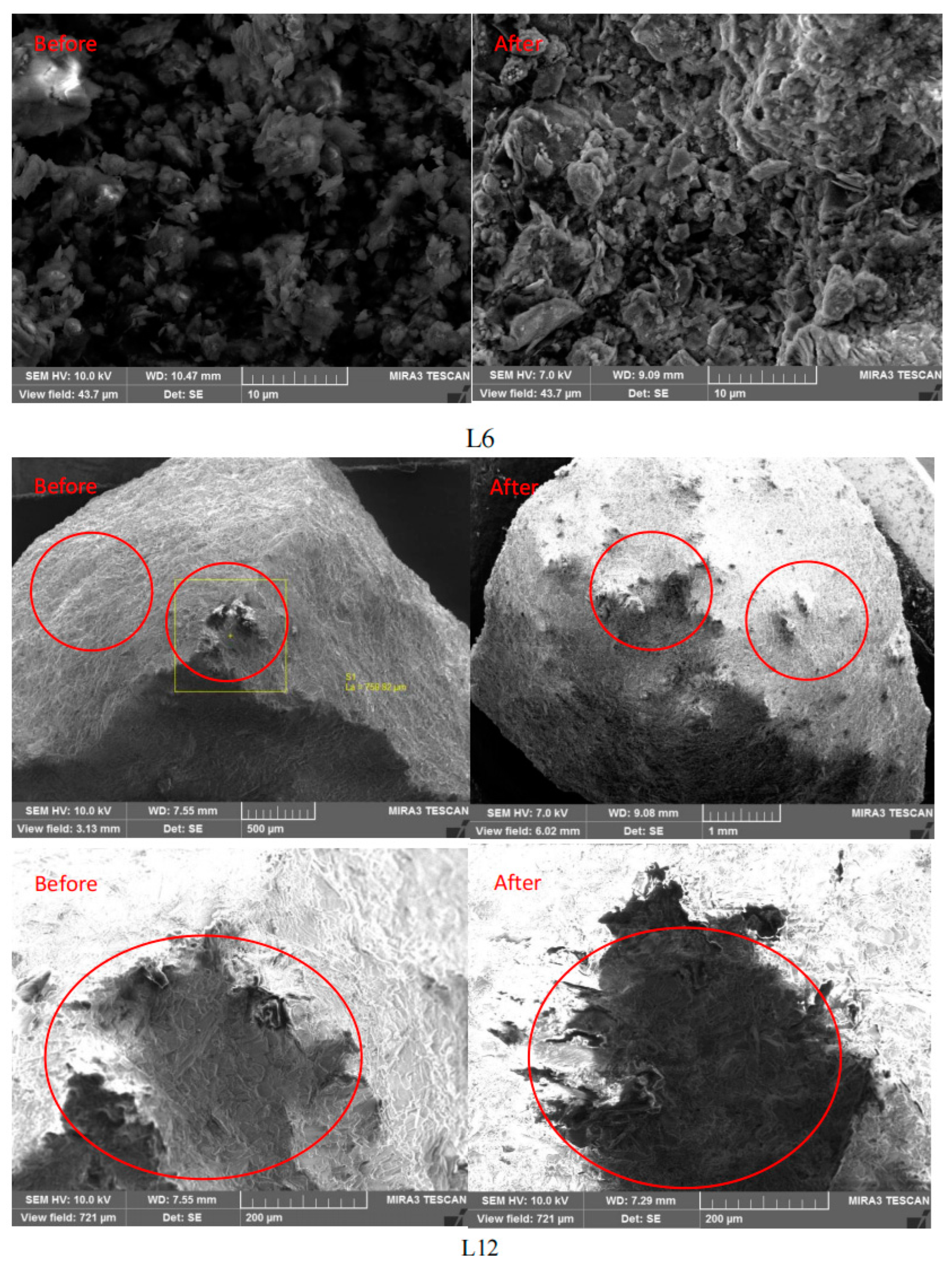
Micrographs of shale grains before and after saturation with different fluids were obtained through SEM measurements. The SEM results of the shale samples before and after saturation are shown in Figure 2. Though variations in the same position of shale were sought, it was very hard to reach the same position due to the reaction between shale and fluids in the long term. Some regions of shale were marked in advance, while the marked regions were missing in the final SEM detection.
In general, shale has high clay and organic matter contents, and pores in shale can be divided into interparticle pores, intraparticle pores, organic matter pores, and fractures. For the shale gas reservoirs, the pore system provided a significant internal surface area and pore volume. As shown in Figure 2, it was found that the shale had abundant pore structures; after 6 MPa CO2 and 12 MPa CO2 saturation, the surface of the shale sample became rougher, small bumps and cracks appeared on the shale, while the pores in the shale seem to be squeezed, which may have been caused by the adsorption induced matrix swelling/shrinkage [34]. The adsorption capacity of shale was closely related to the gas pressure, and it was positively correlated with the amount of swelling; thus, the gas pressure directly affected the volume swelling deformation. It can be inferred that the pore structure alterations of shale under 6 MPa CO2 saturation were more obvious than those under 12 MPa CO2 saturation. Unlike the CO2 saturation, after being saturated with CO2+brine, some obvious tiny pores were generated on the surface of the shale, which indicated that ion exchanges may happen inside the shale. It can be seen that these tiny pores connected into the shale, suggesting that the permeability of the shale cap would increase and security risks arise after a period of CO2+brine sequestration [35]. Moreover, significant corrosion and dissolution were found in CO2+brine-saturated shale samples, and some blocks of shale were missing (Figure 2). This was because of the generation of H+-dissolved minerals such as calcite, dolomite, kaolinite, illite, and K-feldspar (Equations (1)–(5) and (7)), resulting in a decrease in carbonate mineral contents. Mineral corrosion and dissolution induced increases in the porosity, average pore size, and specific surface area of micropores and mesopores in shale, as they induced the micropores and mesopores in shale to gradually transform into macropores. Generally, the higher the pressure of CO2, the greater the amount of CO2 dissolved in solution, and the lower the pH, leading to remarkable mineral corrosion and dissolution. In addition, new minerals were formed on the surface and inside the shale after CO2+brine saturation, which further verified that the chemical reaction produced now precipitated substances, and these flocculent substances also changed the pore structure of the shale, possibly because the dissolution of the minerals consumed protons in an acid solution, increasing its pH. As the pH value rose to a certain extent and the mineral ion concentration achieved a certain level, mineral precipitation occurred. Compared with shale saturated with CO2 at 6 MPa and 12 MPa, the phenomenon of matrix swelling/shrinkage was not obvious, although the shale displayed a strong adsorption of water. This may be related to the content of clay minerals expanded with water in shale, and the swelling inhibition effect of cations in fluids.
After being saturated with CO2/brine, the CO2/brine–shale interaction triggered mineral dissolution and precipitation in shale, as well as the extraction induced by the ScCO2 dissolution effect on some special organic matter. Furthermore, CO2/brine filled in the pores of shale, being absorbed and adsorbed in shale, inevitably affecting the morphology and pore structure of shale. In a word, the pore structure alterations can be impacted by mineral dissolution/precipitation, ScCO2 extraction, and CO2/brine adsorption/desorption-induced matrix swelling/shrinkage, each of which was closely related to the kind of saturated fluid and the pressure of the gas. To some extent, the SEM measurements can only judge the changes in pore structure qualitatively, while to evaluate the pore structure alterations quantitatively, it was necessary to conduct the low-pressure gas adsorption test.

3.3. Low-Pressure Gas Adsorption Test

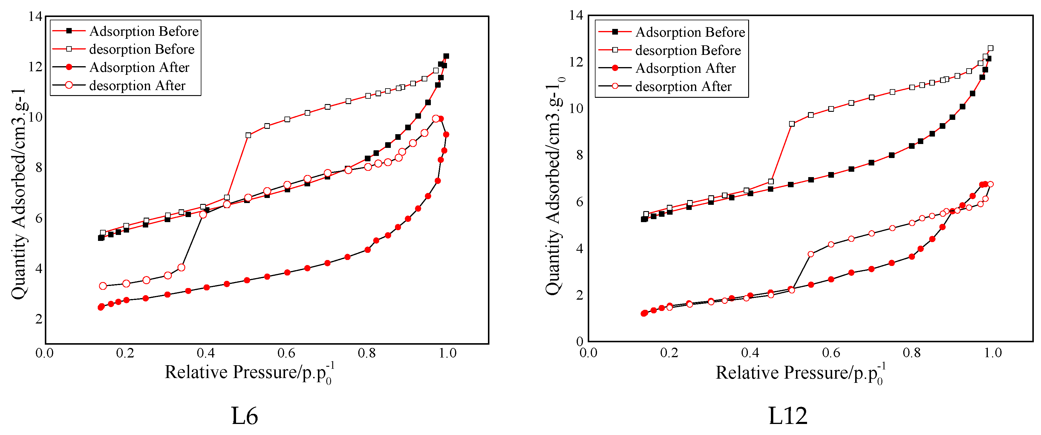
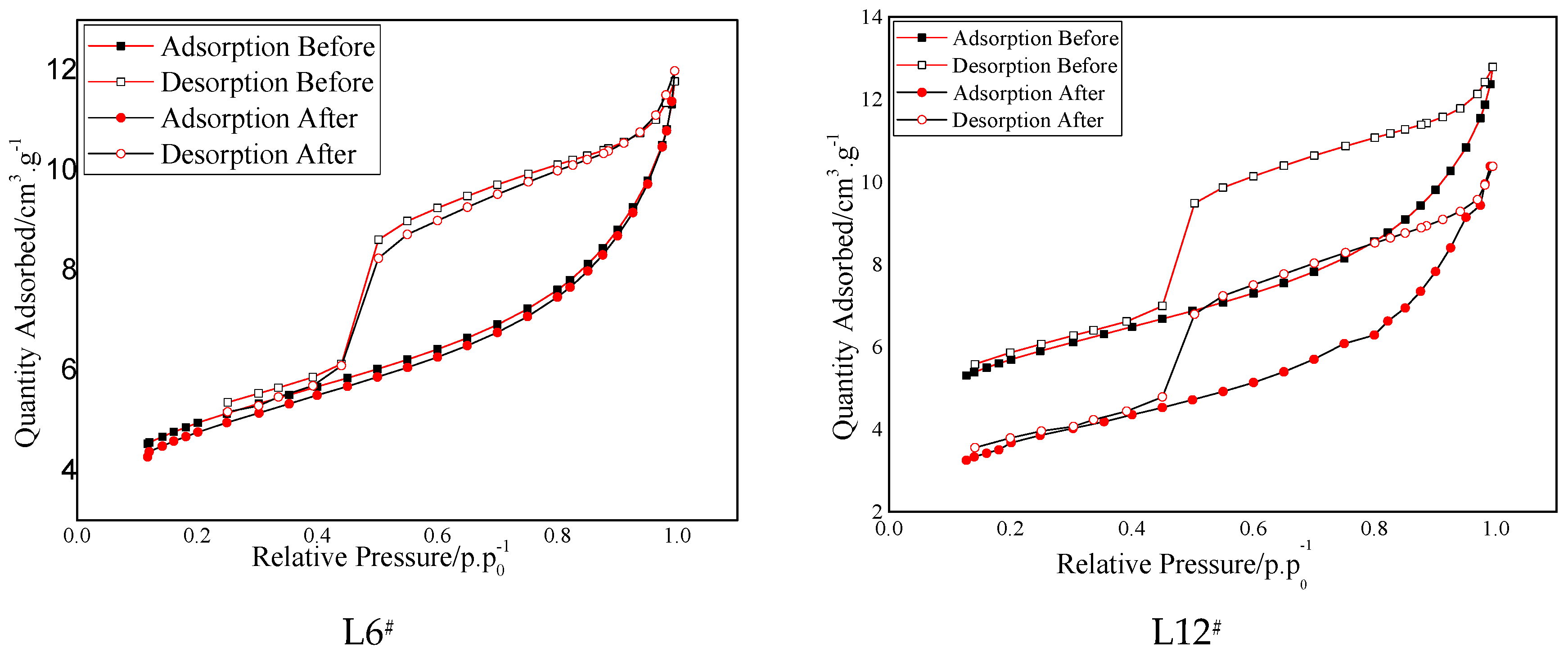
The nitrogen adsorption isotherms of eight samples of Longmaxi shale before and after saturation with different fluids are displayed in Figure 3. All the adsorption isotherms showed similar morphological patterns in shale samples. During the adsorption process, the adsorbed gas quantity increased gradually as the relative pressure increased from 0 to 0.8, and then increased rapidly until it reached the maximum relative pressure. The isotherm curves present an anti-S-shape and the isotherms can be classified as Type II based on the IUPAC category of pore shapes [11], which indicates that a multilayer adsorption behavior occurred in these shale samples. The adsorption–desorption isotherms formed an obvious hysteresis loop at a relative pressure of 0.4–0.99, and each hysteresis loop displayed similar morphological attributes, which can be categorized as type H3 and type H4 [11], which revealed the complexity of the pore structure and demonstrated slit-type pores and open pores existing in the shale.
After saturation with different fluids, the curves of the isotherms moved down to a certain extent at all stages of relative pressure, the maximum quantity of adsorbed N2 of all the samples decreased, and the hysteresis loops became narrower, which suggested that the obstruction of gas molecule movement was reduced and the connectivity of pores was enhanced, and it can be inferred that the proportion of mesopores and macropores increased due to more gas flow channels being offered by mesopores and macropores in shale. This further meant that the permeability of shale may be enhanced and the risk of CO2 sequestration may increase [36]. As shown in Figure 3, saturation with different fluids decreased the nitrogen adsorption ability of the shale sample primarily because the adsorption ability was largely controlled by micropores, which provided lots of specific surface areas and adsorption sites. As CO2 saturation induced mineral dissolution/precipitation, extraction and swelling/shrinkage, a portion of the pore space and pore throats were thus dissolved, collapsed and ultimately blocked in shale. It can be concluded that the interaction of shale with different fluids had a great influence on the pore structures of the shale samples in this study. Through further analyzing the results of low-pressure gas adsorption, the pore structure parameters are summarized in Table 4.
The surface area of the pores in the samples was determined using the BET equation, and the special surface area varied from 10.09 m2/g to 5.55 m2/g, 16.51 m2/g, and 12.33 m2/g after saturation with different fluids. After 6 MPa CO2 saturation, the SSA decreased from 18.77 m2/g to 10.09 m2/g with 46.24% reduction and decreased from 18.87 m2/g to 5.55 m2/g with 70.6% reduction, which indicated that although SubCO2 dramatically affected the pore structure of shale, the ScCO2 had a more significant effect than that of SubCO2. After the addition of brine, the reduction in SSA was alleviated. The reduction in SSA is 3.10% and 36.20% in samples L6# and L12#, respectively, which suggested that the addition of brine can inhibit the SSA decrease caused by CO2 to some extent. As the gas pressure increased, the reduction in SSA increased from 46.24% to 70.60% and from 3.10% to 36.20% for shale samples without brine and shale samples with brine, respectively, which indicated that the gas pressure and phase state displayed a remarkable impact on the pore structure of shale.
The pore volume and pore size of shale samples were derived from the BJH desorption and BJH adsorption models, respectively. As can be seen in Table 4, the total pore volume decreased from 1.51 m3·g−1 to 1.44 m3·g−1 with a 4.6% reduction for shale samples under 6 MPa CO2 saturation, and the reduction in pore volume was 30.1%, 2.7% and 5.8% in samples L12, L6# and L12#, respectively. Meanwhile, the pore size increased after fluid saturation, and the pore size increased from 6.25 nm to 7.91 nm with a 26.6% increment for shale samples under 6 MPa CO2 saturation, and the pore size of L12, L6#, and L12# increased by 45.1%, 3.2%, and 8.2%, respectively. These results further illustrate that adding brine can partially inhibit pore structure alteration, and the gas pressure and phase state of CO2 showed great influence in CO2 geological sequestration. Interestingly, the shale sample saturated with 12 MPa CO2 displayed the highest variation in special surface area, pore volume, and pore size. This suggests that ScCO2 had the greatest impact on the pore structure. It is also noteworthy that the variation in pore volume and pore size followed a similar trend to the special surface area when different fluids were used for saturation.
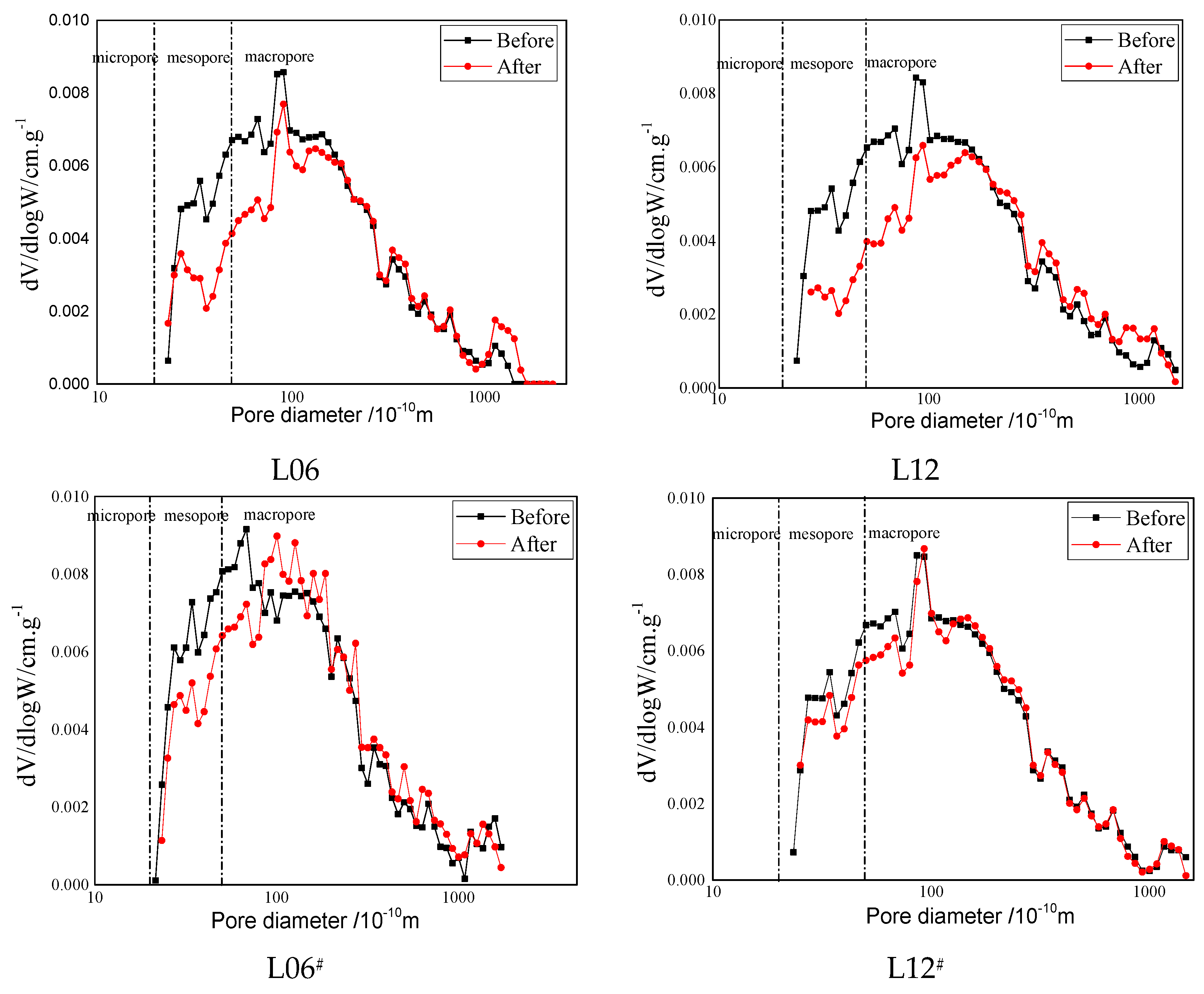
The BJH desorption model was used to calculate the pore size distribution of shale under varying fluid saturation levels. The results are presented in Figure 4. The ordinate parameter dV/d log W was referred to as the log differential pore volume versus diameter. At every stage of pore diameter, it was apparent that each curve of the pore size distribution exhibited a noticeable difference. The curves were skewed towards larger pore sizes, indicating a decrease in the number of micropores due to the reaction between shale and different fluids. Table 5 shows the distribution and percentage of pore volume of shale samples treated with different fluids. It was seen that the pore volume was mainly contributed by mesopores and macopores, with the percentage varying from 20.10% to 31.27% and from 44.44% to 75.97%, respectively. After saturation with different fluids, the total pore volume decreased (Table 4), and the pore volume of micropores also decreased, in particular for the shale-saturated 6 MPa and 12 Mpa CO2, varying from 36.53 to 6.38 and from 37.10 to 4.21, respectively. Following the saturation with different fluids, there was a notable alteration in the percentage of pore volume for both micropores and macropores. This was determined by analyzing the pore volume percentage of pore diameter variation. The outcomes of the pore size distribution indicated that the fluid saturation had a significant impact on both micropores and macropores.
Exposure to various fluids caused violent physical and chemical reactions in shale, resulting in significant changes to its pore structure. The increase in the number of larger pores improves pore connectivity and provides more flow conduits. Ultimately, this is expected to improve the permeability of the shale matrix during CO2 sequestration. Although laboratory investigation and field practices have proven the feasibility of storing CO2 in shale while enhancing hydrocarbon production recovery, it is important to emphasize that future research is necessary to address fundamental issues associated with CO2 sequestration. The Longmaxi Formation in Sichuan Basin, China, as the main site for shale gas exploration and development [37], is identified as the prospective target formation for CO2 sequestration, and much more research is badly needed. Although this paper found that fluid saturation affects shale formations, it should be noted that there are differences between brine and actual underground conditions. Shale formations experience compaction due to pressure from the Earth’s crust [19], which may change the swelling/shrinkage direction and decelerate the physicochemical activity rates in the process of CO2 sequestration. Thus, the comparison between the laboratory results and the reservoir conditions requires further investigation.

4. Conclusions

Samples collected from the Longmaxi Formation shale in Sichuan Basin, China, were exposed to different fluids for 100 days, to determine the effect that CO2 storage has on the mineral composition and pore structure of shale. To do so, the XRD, XRF, SEM, and gas adsorption tests were conducted on the shale samples. After conducting research, the following conclusions were drawn:
  • The XRF analysis revealed that the content of Si increased slightly, while Ca, Al, Fe, and K contents decreased to 10.34%, 3.36%, and 1.37%, respectively, with the increase in CO2 pressure and the addition of brine. XRD results showed that the Longmaxi shale was mainly composed of quartz, dolomite clay, and calcite, with a total content of over 80%, and the content of quartz and dolomite increased, while the content of clay and calcite decreased slightly after saturation.
  • The FESEM analysis results indicate that the surface of the shale sample became rougher, and small bumps and cracks appeared on the shale after saturation with different fluids, revealing mineral dissolution/precipitation, swelling/shrinkage, and development of fractures after long-term exposure to CO2/brine.
  • Based on the low-pressure gas adsorption test results, the curves of the isotherms moved down to a certain extent at all the stages of relative pressure. The special surface area decreased sharply after saturation, in particular for the shale saturated with 6 MPa and 12 MPa CO2. In addition, the variation of total pore volume and the pore size showed a similar trend to the special surface areas and reached the maximum variation for the shale saturated with 12 MPa CO2, which indicates that the gas pressure and phase state displayed a remarkable impact on the pore structure of shale.
  • The curves of pore size distribution were skewed to larger pore sizes at all diameters, indicating that the number of pores decreased as a result of the reaction, while also illustrating that the effect of saturation with different fluids was mainly concentrated in the micropores and macropores.

Author Contributions

Conceptualization, S.Z. and L.Z.; methodology, L.Z.; software, S.Z.; validation, Z.S., Y.H. and L.Z.; formal analysis, L.Z.; investigation, Y.H.; resources, Z.S.; data curation, Z.S.; writing—original draft preparation, Z.S.; writing—review and editing, Q.R. and Z.Z.; visualization, S.Z.; supervision, Y.H.; project administration, Y.H.; funding acquisition, Y.H. All authors have read and agreed to the published version of the manuscript.

Funding

This research was funded by the Natural Science Foundation of Hunan Province (Grant no 2020JJ5494, 2023JJ40546), the research project of the Education Department of Hunan Province (Grant no 21A0264), and the State Key Laboratory of Safety and Health for Metal Mines (2021-JSKSSYS-08).

Data Availability Statement

The data presented in this study are available upon request from the corresponding author. The data are not publicly available because some of the basic research involves confidentiality.

Acknowledgments

We are grateful to the editors and reviewers for their constructive comments and suggestions.

Conflicts of Interest

The authors declare no conflict of interest.

References

  1. Mansi, M.; Almobarak, M.; Lagat, C.; Xie, Q. Statistical Analysis of Controlling Factors on Enhanced Gas Recovery by CO2 Injection in Shale Gas Reservoirs. Energy Fuels 2023, 37, 965–976. [Google Scholar] [CrossRef]
  2. Arab, Oil, Gas, and Group, World Energy Outlook 2011 by the International Energy Agency. Arab Oil & Gas. 2011. Available online: https://www.iea.org/reports/world-energy-outlook-2011 (accessed on 24 October 2023).
  3. Gholamic, R.; Raza, A.; Iglauer, S. Leakage risk assessment of a CO2 storage site: A review. Earth-Sci. Rev. 2021, 223, 103849. [Google Scholar] [CrossRef]
  4. Li, J.; Chen, Z.; Wu, K.; Zhang, L.; Hui, G.; Yang, M. Molecular dynamics computations of brine-CO2/CH4-shale contact angles: Implications for CO2 sequestration and enhanced gas recovery. Fuel 2020, 280, 118590. [Google Scholar]
  5. Fatah, A.; Ben Mahmud, H.; Bennour, Z.; Hossain, M.; Gholami, R. Effect of supercritical CO2 treatment on physical properties and functional groups of shales. Fuel 2021, 303, 121310. [Google Scholar] [CrossRef]
  6. Zhan, J.; Chen, Z.; Zhang, Y.; Zheng, Z.; Deng, Q. Will the future of shale reservoirs lie in CO2 geological sequestration? Sci. China Technol. Sci. 2020, 63, 10. [Google Scholar] [CrossRef]
  7. Zhou, J.; Tian, S.; Xian, X.; Zheng, Y.; Yang, K.; Liu, J. Comprehensive Review of Property Alterations Induced by CO2-shale Interaction: Implications for CO2 Sequestration in Shale. Energy Fuels 2022, 36, 8066–8080. [Google Scholar] [CrossRef]
  8. Ilgen, A.G.; Aman, M.; Espinoza, D.N.; Rodriguez, M.A.; Griego, J.M.; Dewers, T.A.; Feldman, J.D.; Stewart, T.A.; Choens, R.C.; Wilson, J. Shale-brine-CO2 interactions and the long-term stability of carbonate-rich shale caprock. Int. J. Greenh. Gas Control. 2018, 78, 244–253. [Google Scholar] [CrossRef]
  9. Fatah, A.; Ben Mahmud, H.; Bennour, Z.; Gholamic, R.; Hossain, M. Geochemical and physical alteration of clay-rich shales under supercritical CO2 conditions. Appl. Geochem. J. Int. Assoc. Geochem. Cosmochem. 2022, 140, 105291. [Google Scholar] [CrossRef]
  10. Marcon, V.; Kaszuba, J.P. Carbon dioxide–brine–rock interactions in a carbonate reservoir capped by shale: Experimental insights regarding the evolution of trace metals. Geochim. Et Cosmochim. Acta 2015, 168, 22–42. [Google Scholar] [CrossRef]
  11. Zhou, D.; Zhang, G.; Huang, Z.; Zhao, J.; Wang, L.; Qiu, R. Changes in microstructure and mechanical properties of shales exposed to supercritical CO2 and brine. Int. J. Rock Mech. Min. Sci. 2022, 160, 105228. [Google Scholar] [CrossRef]
  12. Harris, R.K.; Kowalewski, J.; Menezes, S.C.D. International Union of Pure and Applied Chemistry Physical Chemistry Division Commission on Molecular Structure and Spectroscopy. Parameters and symbols for use in nuclear magnetic resonance (IUPAC recommendations 1997). Magn. Reson. Chem. 1998, 36, 145–149. [Google Scholar] [CrossRef]
  13. Tan, J.; Hu, C.; Lyu, Q.; Dick, J.M.; Ranjith, P.G.; Li, L.; Wang, Z. Multi-fractal analysis for the AE energy dissipation of CO2 and CO2+ brine/water treated low-clay shales under uniaxial compressive tests. Fuel 2019, 246, 330–339. [Google Scholar] [CrossRef]
  14. Dai, X.; Wei, C.; Wang, M.; Ma, R.; Song, Y.; Zhang, J.; Wang, X.; Shi, X.; Vandeginste, V. Interaction mechanism of supercritical CO2 with shales and a new quantitative storage capacity evaluation method. Energy 2023, 264, 126424. [Google Scholar] [CrossRef]
  15. Zhang, S.; Xian, X.; Zhou, J.; Zhang, L. Mechanical behavior of Longmaxi black shale saturated with different fluids: An experimental study. RSC Adv. 2017, 7, 42946–42955. [Google Scholar] [CrossRef]
  16. Qin, C.; Jiang, Y.; Zhou, J.; Zuo, S.; Chen, S.; Liu, Z.; Yin, H.; Li, Y. Influence of supercritical CO2 exposure on water wettability of shale: Implications for CO2 sequestration and shale gas recovery. Energy 2022, 242, 122551. [Google Scholar] [CrossRef]
  17. Yekeen, N.; Khan, J.A.; Ali, M.; Elraies, K.A.; Okunade, O.A.; Ridha, S.; Al-Yaseri, A. Impact of nanoparticles–surfactant solutions on carbon dioxide and methane wettabilities of organic-rich shale and CO2/brine interfacial tension: Implication for carbon geosequestration. Energy Rep. 2022, 8, 15669–15685. [Google Scholar] [CrossRef]
  18. Sanguinito, S.; Goodman, A.; Tkach, M.; Kutchko, B.; Culp, J.; Natesakhawat, S.; Fazio, J.; Fukai, I.; Crandall, D. Quantifying dry supercritical CO2-induced changes of the Utica Shale. Fuel 2018, 226, 54–64. [Google Scholar] [CrossRef]
  19. Lu, Y.; Chen, X.; Tang, J.; Li, H.; Zhou, L.; Han, S.; Ge, Z.; Xia, B.; Shen, H.; Zhang, J. Relationship between pore structure and mechanical properties of shale on supercritical carbon dioxide saturation. Energy 2019, 172, 270–285. [Google Scholar] [CrossRef]
  20. Li, N.; Jin, Z.; Zhang, S.; Wang, H.; Yang, P.; Zou, Y.; Zhou, T. Micro-mechanical properties of shale due to water/supercritical carbon dioxide-rock interaction. Pet. Explor. Dev. 2023, 50, 1001–1012. [Google Scholar] [CrossRef]
  21. Alafnan, S. Utilization of supercritical carbon dioxide for mechanical degradation of organic matters contained in shales. Fuel 2022, 316, 123427. [Google Scholar] [CrossRef]
  22. Hazarika, S.; Boruah, A.; Kumar, H. Study of pore structure of shale formation for CO2 storage. Mater. Today Proc. 2023. [Google Scholar] [CrossRef]
  23. Yang, K.; Zhou, J.; Xian, X.; Zhang, C.; Gan, Q.; Dong, Z. Effect of supercritical CO2-water-shale interaction on mechanical properties of shale and its implication for carbon sequestration. Gas Sci. Eng. 2023, 111, 204930. [Google Scholar] [CrossRef]
  24. Ozotta, O.; Liu, K.; Gentzis, T.; Carvajal-Ortiz, H.; Ostadhassan, M. Pore Structure Alteration of Organic-Rich Shale with Sc-CO2 Exposure: The Bakken Formation. Energy Fuels 2021, 35, 5074–5089. [Google Scholar] [CrossRef]
  25. Yang, R.; He, S.; Wang, X.; Hu, Q.; Hu, D.; Yi, J. Paleo-ocean redox environments of the Upper Ordovician Wufeng and the first member in lower Silurian Longmaxi formations in the Jiaoshiba area, Sichuan Basin. Can. J. Earth Sci. 2016, 53, 426–440. [Google Scholar] [CrossRef]
  26. Liu, S.; Ma, W.; Jansa, L.; Huang, W.; Zeng, X.; Zhang, C. Characteristics of the shale gas reservoir rocks in the Lower Silurian Longmaxi Formation, East Sichuan Basin, China. Energy Explor. Exploit. 2013, 31, 187–219. [Google Scholar] [CrossRef]
  27. Fatah, A.; Mahmud, H.; Bennour, Z.; Gholamic, R.; Hossain, M. Geochemical modelling of CO2 interactions with shale: Kinetics of mineral dissolution and precipitation on geological time scales. Chem. Geol. 2022, 592, 120742. [Google Scholar] [CrossRef]
  28. Al-Yaseri, A.; Abu-Mahfouz, I.S.; Yekeen, N.; Wolff-Boenisch, D. Organic-rich source rock/H2/brine interactions: Implications for underground hydrogen storage and methane production. J. Energy Storage 2023, 63, 106986. [Google Scholar] [CrossRef]
  29. Jung, H.B.; Um, W.; Cantrell, K.J. Effect of oxygen co-injected with carbon dioxide on Gothic shale caprock–CO2–brine interaction during geologic carbon sequestration. Chem. Geol. 2013, 354, 1–14. [Google Scholar] [CrossRef]
  30. Sakthivel, S.; Yekeen, N.; Theravalappil, R.; Al-Yaseri, A. Influence of carbon nanodots on the Carbonate/CO2/Brine wettability and CO2-Brine interfacial Tension: Implications for CO2 geo-storage. Fuel 2024, 355, 129404. [Google Scholar] [CrossRef]
  31. Fatah, A.; Mahmud, H.B.; Bennour, Z.; Gholamic, R.; Hossain, M. The impact of supercritical CO2 on the pore structure and storage capacity of shales. J. Nat. Gas Sci. Eng. 2022, 98, 104394. [Google Scholar] [CrossRef]
  32. Lyu, Q.; Wang, K.; Hu, C.; Shi, J.; Tan, J.; Zhang, G.; Chen, S.; Ranjith, P.G. Effects of supercritical CO2/water imbibition under dynamic pressures on shale mechanics and acoustic emission characteristics. Fuel 2022, 321, 124087. [Google Scholar] [CrossRef]
  33. Ozotta, O.; Kolawole, O.; Malki, M.L.; Ore, T.; Gentzis, T.; Fowler, H.; Liu, K.; Ostadhassan, M. Nano- to macro-scale structural, mineralogical, and mechanical alterations in a shale reservoir induced by exposure to supercritical CO2. Appl. Energy 2022, 326, 120051. [Google Scholar] [CrossRef]
  34. Alemu, B.L.; Aagaard, P.; Munz, I.A.; Skurtveit, E. Caprock interaction with CO2: A laboratory study of reactivity of shale with supercritical CO2 and brine. Appl. Geochem. 2011, 26, 1975–1989. [Google Scholar] [CrossRef]
  35. Tan, J.; Hu, C.; Lyu, Q.; Feng, G.; Chen, S. Experimental investigation on the effects of different fracturing fluids on shale surface morphology. J. Pet. Sci. Eng. 2022, 212, 110356. [Google Scholar] [CrossRef]
  36. Lyu, Q.; Shi, J.; Tan, J.; Dick, J.M.; Kang, X. Effects of shale swelling and water-blocking on shale permeability. J. Pet. Sci. Eng. 2022, 212, 110276. [Google Scholar] [CrossRef]
  37. Currenti, G.; Cantucci, B.; Montegrossi, G.; Napoli, R.; Misnan, M.S.; Rashidi, M.R.; Bakar, Z.A.A.; Harith, Z.Z.; Bahri, N.H.; Hashim, N. CO2 Leakage Scenarios in Shale Overburden. Minerals 2023, 13, 1016. [Google Scholar] [CrossRef]
Figure 1. The laboratory setup was used for saturation.
Minerals 13 01387 g001
Figure 2. The morphology of shale before and after saturation with different fluids.
Minerals 13 01387 g002aMinerals 13 01387 g002b
Figure 3. Low-temperature N2 adsorption–desorption isotherms of shale before and after saturation with different fluids.
Minerals 13 01387 g003aMinerals 13 01387 g003b
Figure 4. Pore size distribution of shale treated with different fluids.
Minerals 13 01387 g004
Table 1. The saturation conditions of shale.
Saturation FluidsCarbon Dioxide PressureTemperatureVolume of BrineExposure TimeLabel
CO2 saturation6 MPa45 °C-100 daysL6
CO2 saturation12 MPa45 °C-100 daysL12
10%NaCl (brine) + CO2 saturation6 MPa45 °C300 mL100 daysL6#
10%NaCl (brine) + CO2 saturation12 MPa45 °C300 mL100 daysL12#
Table 2. Results of XRF analysis of shale saturated with different fluids.
Shale SamplesMain Elements (%)
OSiCaAlFeKSMgNaP
Before reaction41.4034.6213.003.652.521.561.031.060.890.06
L0641.6034.5712.953.632.501.541.041.050.890.06
L1242.2535.6211.563.482.431.421.031.100.860.05
L06#43.4135.1610.833.421.861.471.171.071.190.06
L12#44.6036.5410.343.362.091.370.900.961.290.06
Table 3. Results of XRD analysis of shale saturated with different fluids.
Mineralogical AnalysisBefore Saturation
(%, wt)
L6
(%, wt)
L12
(%, wt)
L6#
(%, wt)
L12#
(%, wt)
Quartz44.844.947.146.849.2
Calcite19.819.719.318.417.6
barite1.01.01.11.21.3
plagioclase3.53.43.13.33.0
Dolomite13.914.013.414.215.1
marcasite1.51.51.21.30.9
K-feldspar1.41.41.11.21.0
pyrite5.15.04.84.944.7
analcite0.90.91.00.91.1
clay8.18.27.97.766.1
Table 4. Distribution of pore size, pore volume, and specific surface area of shale before and after saturation with different fluids.
SampleSpecial Surface Area (m2·g−1) (Before/After)Variation (%)Pore Volume (10−2 cm3·g−1)
(Before/After)
Variation (%)Pore Size (nm) (Before/After)Variation (%)
L618.77/10.09−46.24151/144−4.66.25/7.9126.6
L1218.87/5.55−70.60153/107−30.16.34/9.2045.1
L6#17.04/16.51−3.10147/143−2.76.57/6.783.2
L12#19.32/12.33−36.20155/146−5.86.34/6.868.2
Table 5. Pore volume distribution and percentage of shale samples treated with different fluids.
SampleStatePore Volume (10−2 cm3·g−1)Percentage (%)
MicroporeMesoporeMacorporeMicroporeMesoporeMacorpore
L6Before36.5347.3267.4724.1431.2744.58
After6.3832.79104.994.4322.7572.83
L12Before37.1947.2868.6824.2830.8744.84
After4.2121.5681.463.9320.1075.97
L6#Before29.6343.4873.8320.1629.5950.24
After26.7344.1082.7217.4128.7253.87
L12#Before38.1047.9668.8424.6030.9644.44
After12.7640.6392.368.7527.8863.37
Disclaimer/Publisher’s Note: The statements, opinions and data contained in all publications are solely those of the individual author(s) and contributor(s) and not of MDPI and/or the editor(s). MDPI and/or the editor(s) disclaim responsibility for any injury to people or property resulting from any ideas, methods, instructions or products referred to in the content.