Article

A Method for Stabilizing the Vibration Amplitude of a Flip-Flow Vibrating Screen Using Piecewise Linear Springs

1
State Key Laboratory of Comprehensive Utilization of Low-Grade Refractory Gold Ores, Longyan 364200, China
2
School of Chemical and Environmental Engineering, China University of Mining and Technology-Beijing, Beijing 100083, China
3
Zijin School of Geology and Mining, Fuzhou University, Fuzhou 350108, China
*
Author to whom correspondence should be addressed.
Minerals 2024, 14(4), 406; https://doi.org/10.3390/min14040406
Submission received: 9 March 2024 / Revised: 9 April 2024 / Accepted: 10 April 2024 / Published: 16 April 2024
(This article belongs to the Section Mineral Processing and Extractive Metallurgy)

Abstract

:
The flip-flow vibrating screen (FFVS) is a novel multi-body screening equipment that utilizes vibrations to classify bulk materials in the field of screening machinery. The relative amplitude of FFVSs determines the tension and ejection intensity of elastic flip-flow screen panels, which is a critical operating parameter affecting the screening performance. However, FFVSs generally suffer from large variations of relative amplitude caused by the loading of materials and the changes in shear spring stiffness (the temperature changes of the shear springs lead to their stiffness changes), which significantly reduce the screening efficiency and lifespan of FFVSs. To address this problem, this paper proposes a nonlinear stiffness-based method for stabilizing the vibration amplitude of FFVSs using piecewise linear springs. By introducing these springs between the two frames, the sensitivity of the relative amplitude to shear spring stiffness is reduced, thereby achieving the stabilization of the relative amplitude of FFVSs. In this study, the variations of the vibration amplitude of the FFVS due to the loading of materials and the changes in shear spring stiffness were first demonstrated in a reasonable operating frequency range. Then the reasonable operating frequency range and dynamics of the resultant nonlinear flip-flow vibrating screen (NFFVS) with piecewise linear springs were investigated using the harmonic balance method (HBM) and the Runge–Kutta numerical method. The operating frequency region for the NFFVS lies between the critical frequency ω c s and the frequency ω l b corresponding to the saddle-node bifurcation point. Finally, a test rig was designed to validate the theoretical predictions. Theoretical and experimental results demonstrate that piecewise linear springs can effectively stabilize the relative amplitude of the FFVS.

1. Introduction

Vibrations are usually considered to be harmful in many industrial applications and various control methods have been developed to suppress the unwanted vibrations [1,2]. On the other hand, vibrations can be beneficially utilized in some fields, including mining and construction [3,4,5]. Screening, a common process employed in mining and the construction industry, involves classifying particle groups based on their sizes through screen apertures [6,7,8]. Vibrating screening machines are commonly used for classifying and dewatering powder and granular materials, to achieve an ideal particle size distribution and meet production requirements [9,10,11]. Flip-flow vibrating screens (FFVSs) were developed for screening sticky and wet materials, which tend to adhere to each other and block the screen apertures [12,13]. The unique trampoline-like motion of the flip-flow screen panels effectively disaggregates sticky and wet particle groups, loosening and layering the materials. Additionally, the screen panels are not only tensioned but also stretched, up to 2–3 mm, resulting in a slight change in the shape of the screen apertures. This alteration helps prevent sticky grains and near-mesh sized particles (0.75–1 times the aperture size) from blocking the screen apertures. The self-cleaning ability of FFVSs is a distinct advantage that conventional vibrating screens with inflexible screen panels do not possess. As a result, the cut-off size of the novel FFVS is below 3 mm for classifying wet fine materials [12,13,14]. Banana flip-flow screens, a representative type of FFVSs, offer the advantage of equal-thickness screening, which can enhance screening efficiency [15,16].
The dynamic analysis of the FFVSs has attracted significant research attention in recent years. Xiong et al. [16] developed a kinematic model specifically for banana flip-flow screens. Lin et al. [17] performed dynamic tests to investigate the mechanical properties of flip-flow screen panels and proposed a non-load physical model of the FFVS. It should be mentioned that the above-mentioned research was focused on the non-load dynamics of FFVSs (i.e., the processed materials are not considered in the modelling), which has provided a theoretical foundation for the design of the FFVS.
There are two issues arising in the practical applications of the FFVSs, which require research attention. First, in the operation of the FFVS, after loading materials, the designed relative amplitude of FFVSs would experience a considerable reduction. Consequently, the expected screening performance of the screen machine fails to meet the design requirements. Yu et al. [18] observed a reduction in the relative amplitude of an FFVS due to the loading of materials, leading to a decrease in the screening efficiency. Lin et al. [19] conducted a theoretical investigation into the dynamics of the FFVS on loading the materials and demonstrated that the relative amplitude of the FFVS decreased as the processing capacity increased. Li et al. [14] experimentally confirmed that the screening efficiency of an FFVS could decrease with increasing infeed rate.
Second, the main and the floating frames are interconnected by rubber shear springs, which play a crucial role in determining the relative motion between the two frames. The stiffness of rubber springs is susceptible to variations in ambient temperature due to their mechanical properties [20]. Luo et al. [21] conducted dynamic tests on rubber springs and observed a decrease in stiffness with increasing temperature and excitation amplitude. When the ambient temperature increases, the shear spring stiffness decreases, causing the second resonance frequency of FFVSs to shift left. Consequently, the relative amplitude between the main and floating frames increases. This amplified relative amplitude leads to a higher excitation amplitude of shear springs, which, in turn, results in the decreased stiffness. Interactive effects between the relative amplitude of FFVSs and ambient temperature could expedite shear spring failure, leading to the increased maintenance costs.
Piecewise nonlinear vibrating systems can exhibit rich dynamic behavior [22]. The auxiliary spring in the piecewise system helps mitigate the effects of the main spring on the system’s dynamic response [23]. This paper introduces piecewise linear springs between the two frames of the FFVSs to reduce the sensitivity of the relative amplitude of the FFVSs to the loaded materials. Additionally, the piecewise linear springs can effectively suppress excessive vibration when the displacement of the piecewise system exceeds the predetermined gap [24]. Thus, the piecewise liner springs can prevent rubber shear springs from tearing due to large deformation. When the relative displacement exceeds the predetermined gap of the resultant piecewise system, the increased restoring force helps restrain the relative amplitude of the two frames of FFVSs. Dynamic analysis of piecewise systems can be conducted using different methods. For example, Ranjbarzadeh and Kakavand [25] utilized the incremental harmonic balance method to analyze the dynamic response of a symmetrical piecewise nonlinear system. Wang et al. [26] used a hyperbolic tangent function to represent the piecewise restoring force and investigated the vibration reduction of a piecewise linear system using the harmonic balance method (HBM).
In this paper, the nonlinear flip-flow vibrating screen (NFFVS) with piecewise linear springs is proposed to stabilize the relative amplitude between the two frames. A hyperbolic tangent function is used to approximately represent the piecewise nonlinear stiffness and damping for the sake of theoretical analysis. The reasonable operating frequency range and the dynamics of the NFFVS are investigated by both the HBM and Runge–Kutta method. The analytic solutions are subsequently verified through experimental tests. Furthermore, the effects of the dynamic parameters on the dynamics of the NFFVS are revealed.

2. Dynamic Analysis of FFVSs

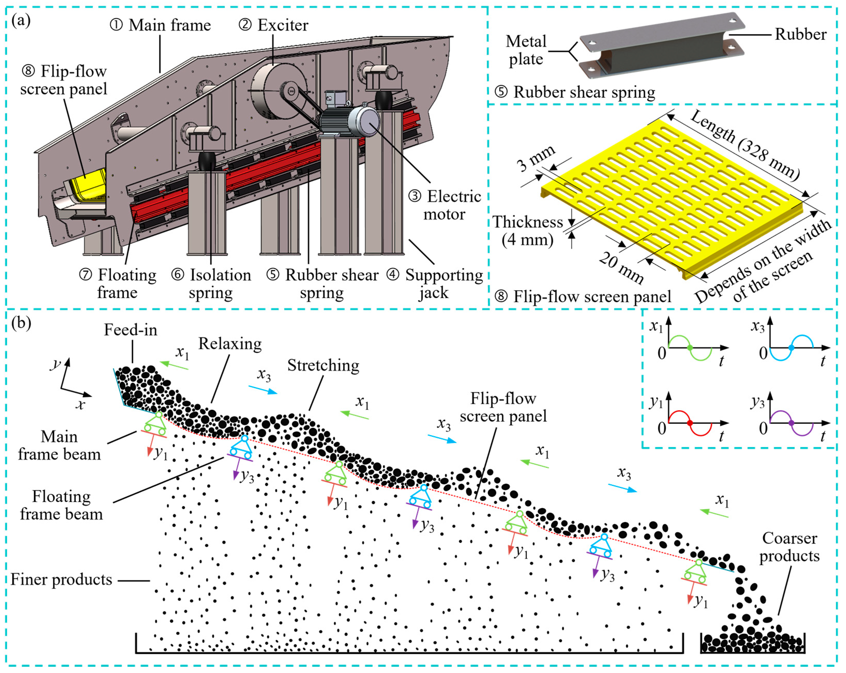
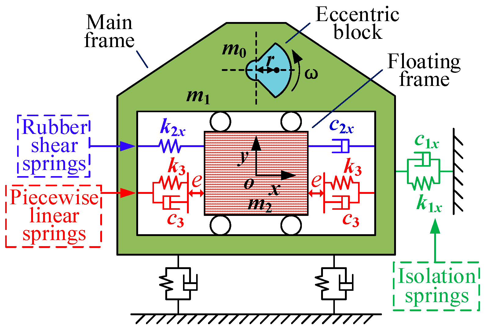
2.1. Structure and Working Principle of FFVSs

The structure of an FFVS is illustrated in Figure 1a, comprising a screen case, an exciter, and an isolation device [17,18]. The screen case serves as the carrier of the FFVS, facilitating the transmission of exciter energy to the particle groups. The screen case primarily consists of a main screen frame, a floating screen frame, shear springs, and flip-flow screen panels. The main screen frame and the floating screen frame are interconnected by metal plates on both sides of the shear springs, allowing for relative motion along the screen surface. The shearing action of the shear springs induces the motion between the two frames. The flip-flow screen panels, made of elastic and wear-resistant polyurethane materials, are attached to the cross beams of the main and floating frames at their respective ends. The screen surface of FFVSs is composed of multiple screen panels arranged in series. The exciter serves as the vibration excitation source for FFVSs and is driven by an electric motor. The rotation of the exciter’s eccentric block generates centrifugal force, resulting in a quasi-circular motion of the screen case. This motion facilitates the screening process. The isolation device consists of rubber isolation springs and supporting jacks, which are responsible for supporting the screen case, reducing dynamic loads on the foundation, and ensuring the stability and reliability of the FFVS.
The working principle of the FFVS is illustrated in Figure 1b. The rotation of the exciter generates centrifugal force, causing the main frame to move in a quasi-circular motion relative to the ground. With the shearing action generated by the shear springs along the screen surface, the floating frame, connected to the main screen frame through the shear springs, undergoes reciprocating linear motion relative to the main frame along the screen surface [12,13,14]. In the direction perpendicular to the screen surface, the high stiffness of the shear springs results in minimal relative movement between the main and the floating frames. The cross beams, which support the flip-flow screen panels, are alternately connected to the main and the floating frames. The relative motion between the two frames leads to a change in the distance between the cross beams. Depending on the operating frequency, the screen panels undergo approximately 720 cycles of stretching and relaxing per minute. The trampoline-like motion of the screen panels effectively disaggregates sticky and wet particle groups, loosening and layering the materials. Consequently, fine materials with sizes smaller than the screen aperture have the opportunity to come into contact with the screen surface and pass through the apertures, becoming finer products. The absolute movement of the main frame relative to the ground, along with the angle of inclination of the screen machine, facilitate the conveyance of materials from the infeed end to the discharge end. Materials that do not pass through the screen apertures are conveyed towards the discharge end, becoming coarser products. It is noteworthy that the flip-flow screen panels not only undergo tensioning but also experience additional stretching of approximately 2–3 mm. This slight change in the shape of the screen apertures effectively prevents wet materials from adhering and blocking the apertures.

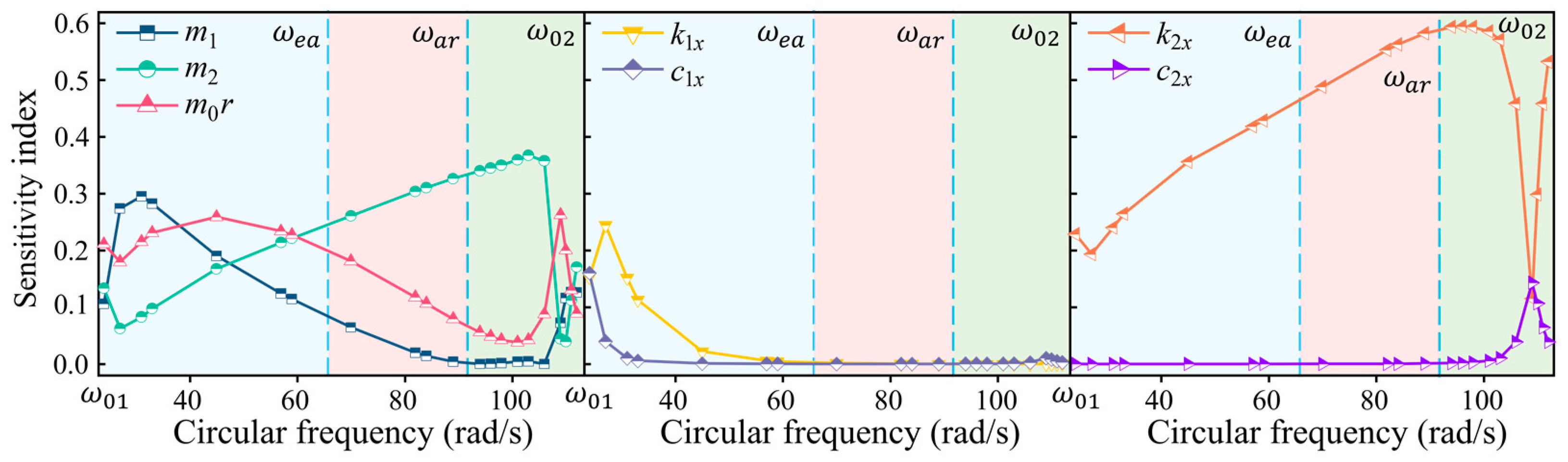
2.2. Reasonable Operating Frequency Region for FFVSs

The FFVS can be classified as a two-mass vibration system in the context of dynamic analysis, and the relative amplitude between the main and floating frames along the screen surface has a significant impact on the screening performance of the FFVS [18,19]. When the FFVS operates within different frequency bands, the loading of materials can cause a certain amount of reduction in the relative amplitude between the two frames [18,19]. Selection of a suitable operating frequency region can mitigate the influence of loading materials and the changes of ambient temperature on the relative amplitude between the two frames. During the screening process of FFVSs, the nonlinear coupling force between the loaded materials and the flip-flow screen panels can be considered as the stiffness force and damping force of the shear spring. The effect of the materials loaded on the dynamics of FFVSs can be equivalently related to the impact of increasing the shear spring stiffness and damping on the dynamic response of the linear FFVS without taking into account the screen panels and the processed materials [19]. The linear dynamic model of FFVSs and its amplitude–frequency response are shown in Figure 2 [18]. On the left side of the first resonance frequency ω 01 of the main screen frame, the two-mass vibration system can be approximated as a single-mass system, resulting in negligible relative motion between the main and floating frames. FFVSs cannot operate effectively within this region, as depicted in Figure 2c. Furthermore, when the relative displacement between the two frames exceeds the slack length of the screen panels, the screen panels undergo stretching deformation, impeding the relative motion between the two frames. This nonlinear behavior restricts the relative movement from surpassing the resonance amplitude of the second resonance region of the screen system [17,19]. Therefore, the appropriate operating frequency band for FFVSs must be chosen between the first resonance frequency ω 01 and the second resonance frequency ω 02 of the main frame. Within this frequency range, the Sobol’s global sensitivity analysis method is employed to investigate the sensitivity of the relative amplitude of an FFVS to its dynamic parameters, revealing the reasonable operating frequency band for the FFVS. The dynamic parameters of the FFS0827 FFVS adhere to a uniform distribution, with a variation range of ±5%, as presented in Table 1. To determine further the reasonable operating frequency band for FFVSs, the equal-amplitude frequency ω e a (the non-zero excitation frequency corresponding to the amplitude of the main frame being equal to the relative amplitude between the main and floating frames) and the anti-resonance frequency ω a r are used to divide the region of the first resonance frequency ω 01 and the second resonance frequency ω 02 into three segments, as shown in Figure 2c.
Figure 3 depicts the variation of the sensitivity of the relative amplitude with the system parameters of the screen in the region of frequency ω 01 and frequency ω 02 . It can be observed that between the first and second resonant frequencies of the main frame, the shear spring stiffness exhibits the highest sensitivity index, followed by the mass of the floating screen frame. Both parameters reach their maximum sensitivity between the anti-resonance frequency ω a r and the second resonant frequency ω 02 . Additionally, within the range of the anti-resonance frequency ω a r and the second resonance frequency ω 02 , the excitation frequency significantly influences the sensitivity of the dynamic parameters of an FFVS, indicating that the relative amplitude between the two frames is more sensitive to the excitation frequency in this region. Consequently, the reasonable operating frequency region for an FFVS should be selected between the first resonance frequency ω 01 and the anti-resonance frequency ω a r . Notably, between the first resonance frequency ω 01 and the equal-amplitude frequency ω e a , the amplitude of the main frame consistently exceeds the relative amplitude between the two frames. Conversely, between the equal-amplitude frequency ω e a and the anti-resonance frequency ω a r , the relative amplitude is larger than the amplitude of the main frame, as shown in Figure 2c. Therefore, when FFVSs operate within the range of the first resonance frequency ω 01 and the equal-amplitude frequency ω e a , a larger amplitude of the main screen frame is required to achieve the same relative amplitude between the equal-amplitude frequency ω e a and the anti-resonance frequency ω a r of the main frame. Consequently, a larger amplitude of the main frame results in a greater dynamic load to the screen case, increases the vibration intensity of the screen machine, and affects the lifespan of the screen machine. In summary, the reasonable operating frequency region for FFVSs lies between the equal-amplitude frequency ω e a and the anti-resonance frequency ω a r of the main frame.

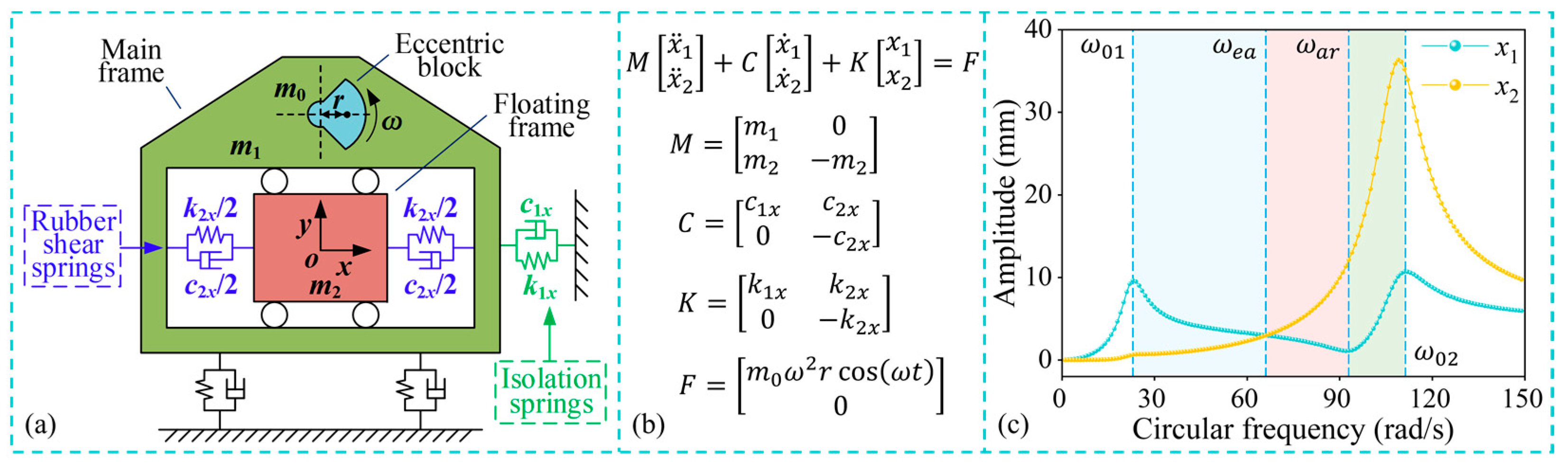
2.3. Loading Dynamics of FFVSs

The interaction between the processed materials and the screen panels during the screening process can be considered as the equivalent stiffness and damping of the shear springs [19]. To study the dynamic behavior of FFVSs under the conditions of continuously loading materials, the average of the lower ( ω e a = k 2 x / 2 m 2 k 2 x c 2 x 2 66   rad / s ) and the upper frequency boundaries ( ω a r k 2 x / m 2 93   rad / s ) is chosen as the operating frequency (79.5 rad/s) to investigate the influence of loading materials on the screening process by increasing the shear spring stiffness. It is important to note that the variation in ambient temperature also affects the stiffness of the shear springs. However, this study focuses solely on investigating the impact of loading materials on the dynamics of FFVSs, while the effect of ambient temperature changes on FFVS dynamics can be treated in a similar way.
Figure 4 illustrates the impact of the materials loaded on the dynamics of an FFVS, specifically when the equivalent stiffness caused by the materials loaded is 10% of the shear spring stiffness. It can be observed that the loading of materials not only increases the amplitude of the main frame, with a change of 11.5%, but also reduces the relative amplitude, with a change of −17.0%. The decrease in relative amplitude would result in a decline in the screening efficiency of FFVSs. Additionally, the increase in the amplitude of the main frame amplifies the vibration intensity of FFVSs, thereby reducing the lifespan of the screen machine. Hence, it is evident that the loading materials have a significant impact on the dynamics of an FFVS.

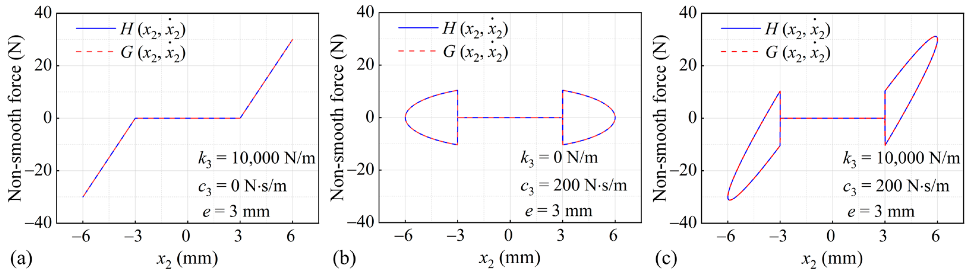
3. A Nonlinear Stiffness-Based Method for Stabilizing Amplitude of FFVSs

To control the displacement of structures in engineering applications, piecewise linear springs are introduced to generate piecewise elastic restoring forces, preventing structural instability [27]. When the structure’s amplitude exceeds the clearance of the piecewise linear spring, the system’s restoring force increases, effectively suppressing structural vibration [28]. Moreover, the strong nonlinearity of piecewise linear springs distorts the backbone curve of the vibration system, thereby effectively stabilizing the system’s amplitude [29]. In this study, a piecewise linear system is incorporated into FFVSs to mitigate the influence of loading materials and variations in shear spring stiffness on the relative amplitude. The dynamic model of the resultant nonlinear FFVS (NFFVS) is depicted in Figure 5. The parameters k 3 and c 3 represent the stiffness ( k 3 = 8100   kN / m ) and damping ( c 3 = 2.605   kN · s / m ) of the piecewise linear springs, while e denotes the clearance of the piecewise linear spring ( e = 6   mm ). Other dynamic parameters are listed in Table 1. When the relative displacement between the main and the floating frames exceeds the clearance of the piecewise linear springs, these springs will actively participate in the system’s vibration, resulting in strong nonlinearity. However, the piecewise linear nonlinearity may induce jump phenomena and regions of multiple solutions in the system’s response, thereby affecting its stability [30]. This paper aimed to reveal the influence of the piecewise linear spring system on the dynamic response of NFFVSs through theoretical analysis and experimental investigation.
According to Newton’s second law, the dynamic differential equation of an NFFVS can be expressed as follows:
{ ( m 1 + m 2 ) x ¨ 1 + c 1 x x ˙ 1 + k 1 x x 1 m 2 x ¨ 2 = m 0 ω 2 r cos ( ω t ) m 2 ( x ¨ 1 x ¨ 2 ) c 2 x x ˙ 2 k 2 x x 2 H ( x 2 , x ˙ 2 ) = 0
H ( x 2 , x ˙ 2 ) = { 0 | x 2 | e k 3 [ x 2 s g n ( x 2 ) e ] + c 3 x ˙ 2 | x 2 | > e
Equation (1) contains a piecewise linear term which is given by Equation (2). To obtain an approximate analytical solution for this equation, the piecewise linear equation can be approximated by fitting it to a continuous function, such as the hyperbolic tangent function [26]:
G ( x 2 , x ˙ 2 ) = [ c 3 x ˙ 2 + k 3 ( x 2 e ) ] { 1 2 [ 1 + tanh ( ε ( x 2 e ) ) ] } + [ c 3 x ˙ 2 + k 3 ( x 2 + e ) ] { 1 2 [ 1 tanh ( ε ( x 2 + e ) ) ] }
where ε is a constant coefficient. A larger value of ε corresponds to a smaller error between the piecewise function H ( x 2 , x ˙ 2 ) and the continuous function G ( x 2 , x ˙ 2 ) . In this paper, the value of ε is chosen as 10 6 .
Figure 6 illustrates the fitting results of the hyperbolic tangent function to the piecewise linear function under various conditions. The results demonstrate that the hyperbolic tangent function can effectively approximate the piecewise linear function.
By replacing the piecewise function H ( x 2 , x ˙ 2 ) with the continuous function G ( x 2 , x ˙ 2 ) , Equation (1) can be transformed into the following:
{ ( m 1 + m 2 ) x ¨ 1 + c 1 x x ˙ 1 + k 1 x x 1 m 2 x ¨ 2 = m 0 ω 2 r sin ( ω t ) m 2 ( x ¨ 1 x ¨ 2 ) c 2 x x ˙ 2 k 2 x x 2 G ( x 2 , x ˙ 2 ) = 0
The HBM can be utilized to obtain an approximate analytical solution for Equation (4), and the stability of this solution can be determined based on the eigenvalues of the Jacobian matrix [28].

4. Dynamic Analysis of NFFVSs

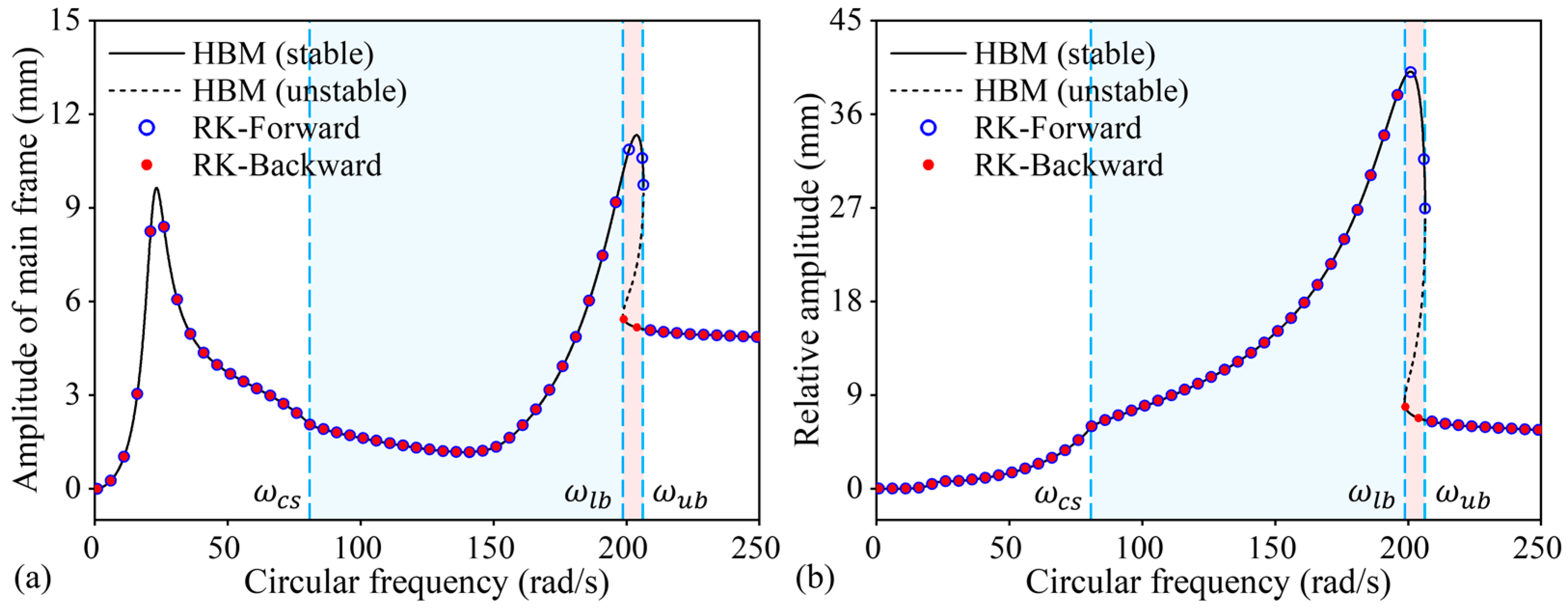
4.1. Operating Frequency Region for NFFVSs

Figure 7 illustrates the comparison between the approximate analytical solution obtained using the third-order HBM and the numerical solution obtained using the forward sweep and backward sweep of the Runge–Kutta method for the nonlinear dynamic equation of an NFFVS. Remarkably, the numerical and analytical solutions exhibit excellent agreement, thus confirming the accuracy of the third-order HBM in solving the clearance nonlinear equation. Within the multi-solution zone, which exists between the excitation frequencies ω l b and ω u b that correspond to the saddle-node bifurcation point, the amplitude of an NFFVS is susceptible to the changes in initial conditions, resulting in distinct dynamic responses for the forward sweep and backward sweep. Furthermore, in the upper branch of the multi-solution zone, a disturbance may cause a transition to the lower branch. Consequently, the reasonable operating frequency region for NFFVSs lies between the critical frequency ω c s , separating linear and nonlinear vibration, and the frequency ω l b , corresponding to the saddle-node bifurcation point.

4.2. Loading Dynamics of NFFVSs

The loading of materials during the screening process of the NFFVS is equivalent to the increase of stiffness and damping forces exerted by the shear spring. By increasing the stiffness of the shear spring, the influence of loading materials on the dynamics of the NFFVS can be revealed. Specifically, the shear spring stiffness is augmented from k 2 x to 1.3 times k 2 x , while other dynamic parameters remain unchanged. Figure 8 depicts the effect of loading materials on the relative amplitude of the NFFVS and FFVS during the screening process. In Figure 8a, the blue region represents the reasonable operating frequency region for the NFFVS, while the red region in Figure 8b signifies the reasonable operating frequency region for the FFVS. As the loading of materials increases, the second resonance frequency of the NFFVS shifts to the right, and the peak value of the second resonance region increases. Given that the excitation frequency remains constant during the operation of the flip-flow screen, the loading of materials during the screening process leads to a reduction in the relative amplitude between the two frames. Figure 8 demonstrates that when the equivalent stiffness of loading materials increases the shear spring stiffness from k 2 x to 1.3 times k 2 x , the minimum reduction in relative amplitude within the reasonable operating frequency region is 1.1 mm, while the maximum reduction is 5.5 mm for NFFVSs. The amplitude decline rates of NFFVSs are 15% and 14%, respectively. On the contrary, the minimum reduction in relative amplitude within the operating frequency region for FFVSs is 1.0 mm, and the maximum reduction is 6.0 mm. The amplitude decline rates of FFVSs are 33% and 49%, respectively. The operating frequency region for the NFFVS is much larger than that for the corresponding FFVS and the frequency region is moved to a higher frequency region. To describe quantitatively the variation of relative amplitude within the reasonable operating frequency region, a linear expression is established to model the relationship between relative amplitude and frequency bandwidth. The intercept of the curves represents the minimum change value of the relative amplitude within the reasonable operating frequency region, while the slope of the curve signifies the rate of variation in relative amplitude with respect to the frequency bandwidth within the reasonable operating frequency band. Consequently, a smaller slope and the intercept of the curve contribute to stabilizing the relative amplitude of the flip-flow screen. Within the reasonable operating frequency region, the intercepts of the NFFVS and FFVS are approximately equal, whereas the slope of the NFFVS is considerably smaller than that of the FFVS. This indicates that the NFFVS can effectively stabilize the relative amplitude during the screening process. Additionally, the NFFVS can operate near the second resonance region and at high frequencies, thereby enhancing the screening efficiency and reducing energy consumption within the system by utilizing the resonance benefits.

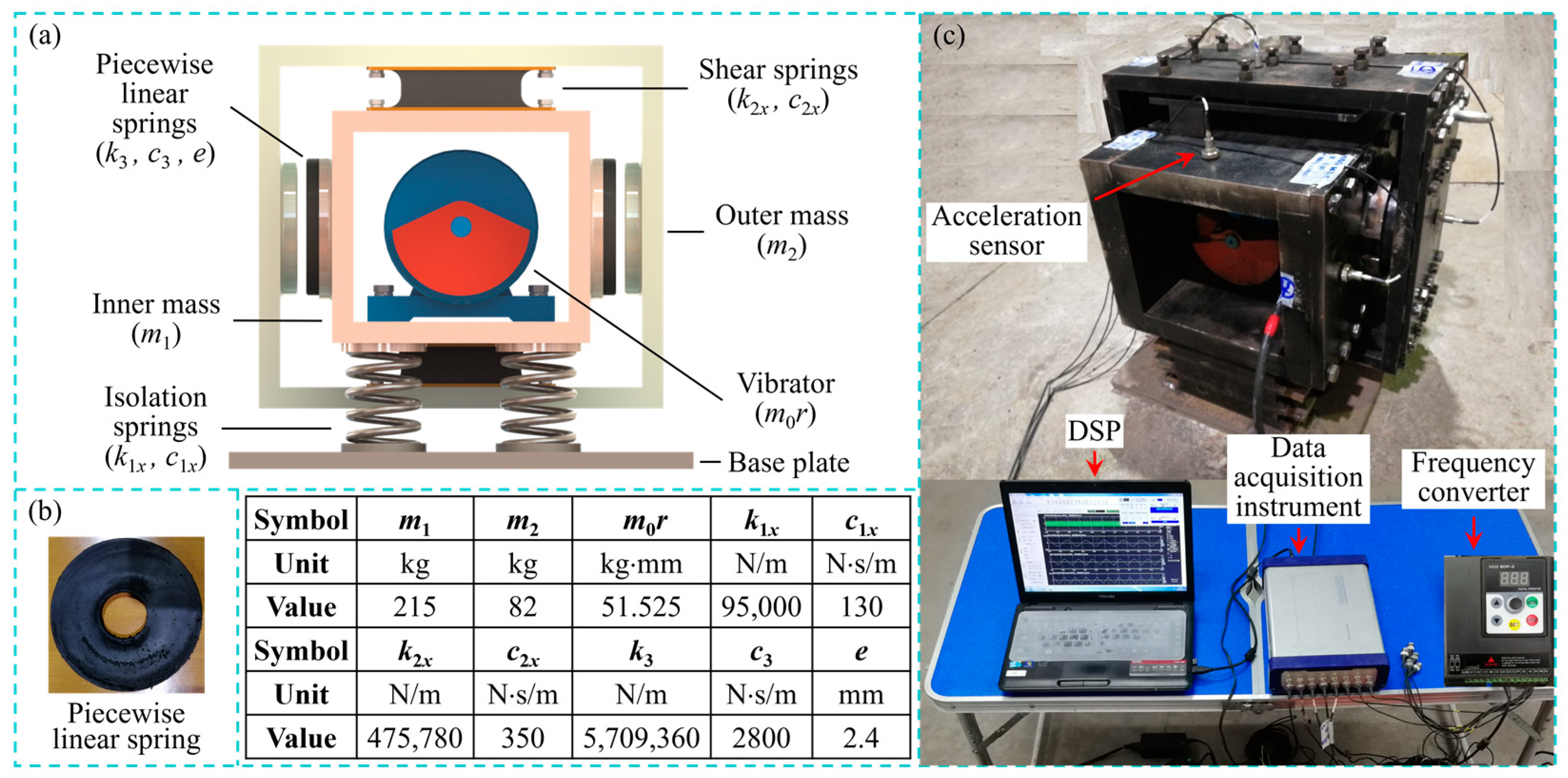
5. Experimental Verification

5.1. Test-Rig and Experimental System

To validate the efficacy of the proposed method for stabilizing the amplitude of FFVSs, a nonlinear dynamic test-rig was designed, as depicted in Figure 9a. The test-rig comprises an inner mass, an outer mass, a vibrator, rubber shear springs, piecewise linear springs, isolation springs, and a base plate. The inner and outer masses are hollow cubes, with the inner mass passing through the outer mass and connected by shear springs. This arrangement enables a relative horizontal movement between the inner and outer masses. Due to the high stiffness of the shear springs in the vertical direction, there is minimal relative motion in that direction. The vibrator (exciter) is installed inside the inner mass, and the rotation of the eccentric block generates centrifugal force that drives the inner mass in a circular motion. Piecewise linear springs are mounted symmetrically on both sides of the inner mass. When the relative displacement between the two masses in the horizontal direction exceeds the clearance of the piecewise linear springs, the outer mass and the piecewise linear spring would come into contact. This contact leads to additional stiffness and damping forces generated by the piecewise linear springs, thereby inducing nonlinear motion of the inner and outer masses in the horizontal direction. Vibration isolation springs were installed between the inner mass and the base plate to reduce the dynamic load on the foundation. Figure 9b illustrates the rubber piecewise linear spring employed in the experiment. The parameters of the test-rig are presented in Figure 9. Acceleration sensors (accelerometers) were positioned in both the horizontal and vertical directions of the inner and outer masses to capture acceleration signals during the experiment, as shown in Figure 9c. A frequency converter was employed to adjust the speed of the vibrator, while the eccentric mass moment was controlled by altering the angle of the eccentric blocks.

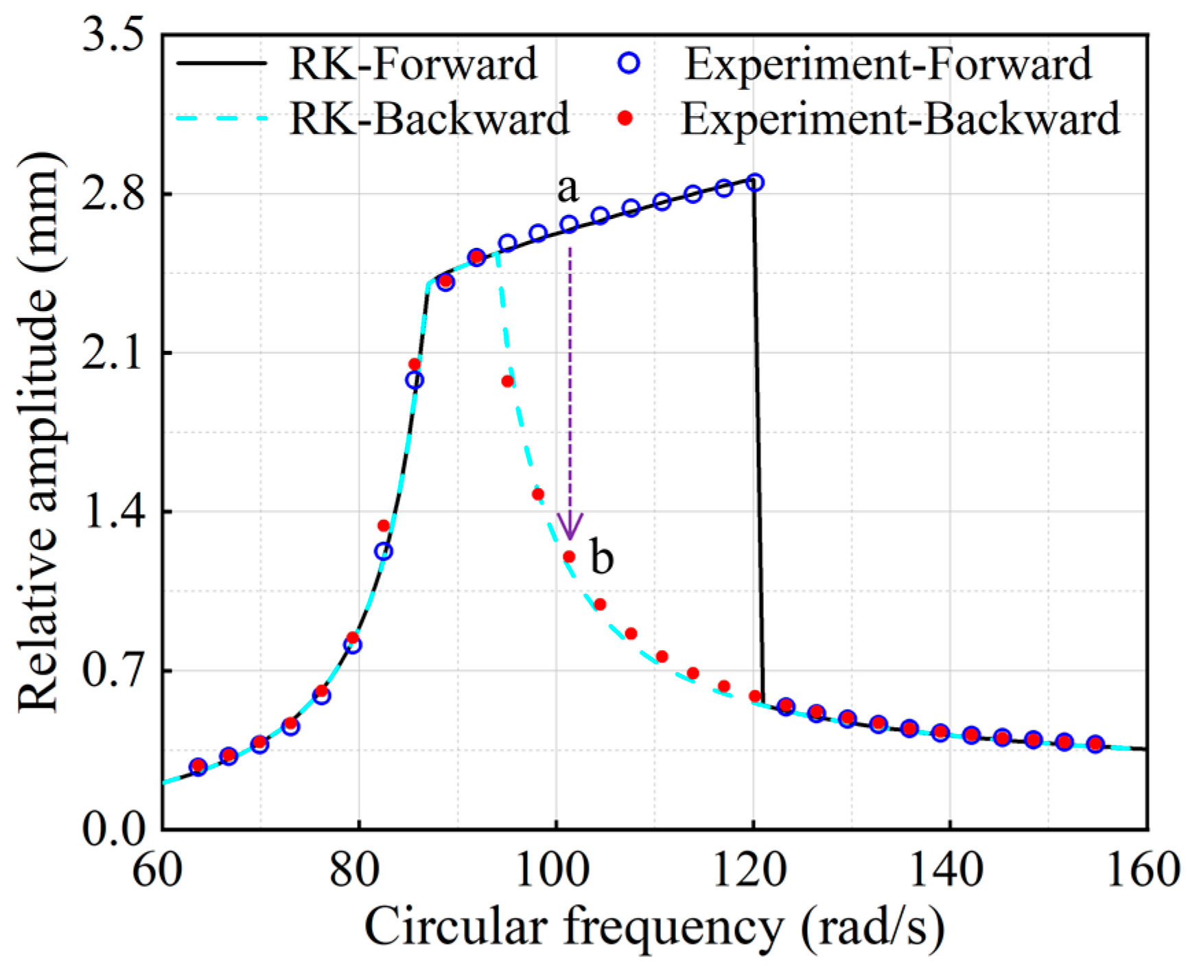
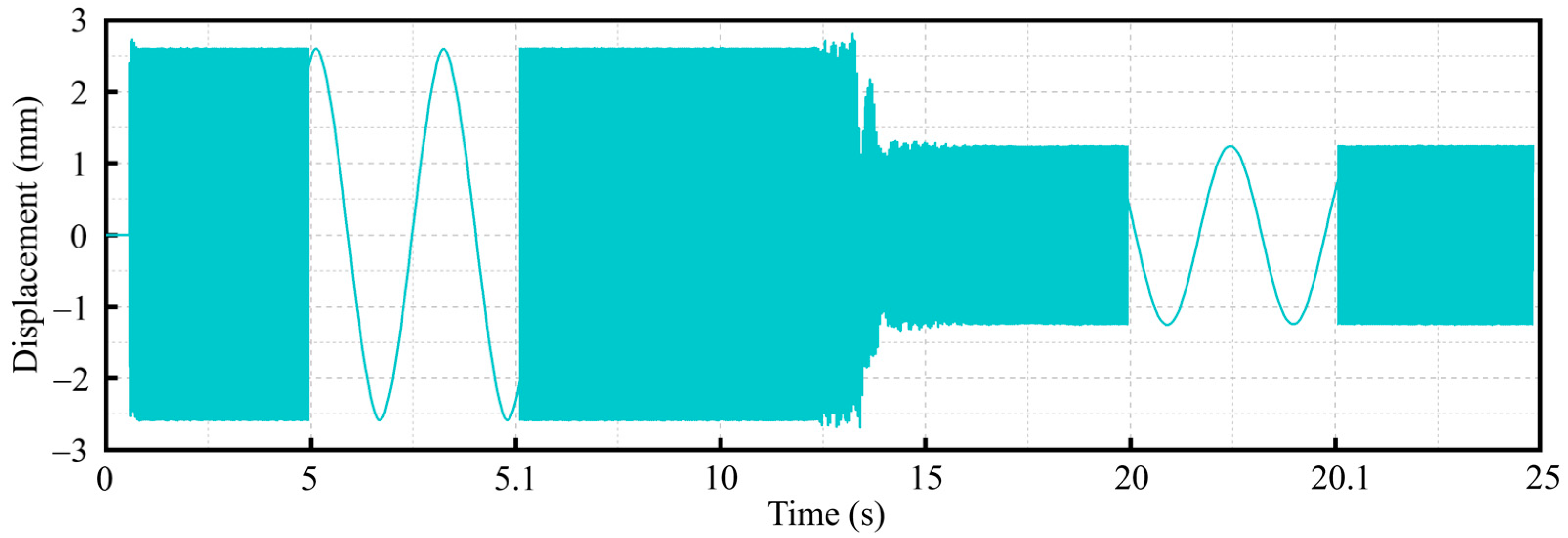
5.2. Experimental Study on Dynamics of NFFVSs

Through the forward and backward sweeps, the amplitude–frequency response of the relative movement between the inner and outer masses along the horizontal direction can be obtained, as shown in Figure 10. During the forward sweep, the excitation frequency is increased from 120.17 rad/s to 123.31 rad/s, and the relative amplitude between the two masses in the horizontal direction suddenly decreases from 2.85 mm to 0.54 mm. Conversely, during the backward sweep, the excitation frequency changes from 95.03 rad/s to 91.89 rad/s, resulting in a sudden increase in the relative amplitude between the inner and outer masses from 1.97 mm to 2.52 mm. This jump phenomenon is a characteristic of nonlinear vibration. The frequency at the jumping point during the backward sweep is smaller than that during the forward sweep, creating a multi-solution zone. The experimental results of the relative amplitude between the two masses perfectly matched the numerical solution obtained using the Runge–Kutta method, thus validating the accuracy of the theoretical analysis presented in this paper.

5.3. Jump Phenomenon in Multi-Solution Zone of NFFVSs

When the nonlinear system operates within the multi-solution zone, jump phenomenon can occur in response to external impacts or disturbances. As the excitation frequency gradually increases, the relative amplitude between the inner and outer masses also increases along the upper branch of the multi-solution zone, as depicted in Figure 10. Within this upper branch, when the test-rig operates at a frequency corresponding to point “a” in Figure 10, the relative amplitude between the inner and outer masses can suddenly jump from a large amplitude at point “a” to a small amplitude at point “b” on the lower branch of the multi-solution zone. Consequently, the multi-solution zone of the nonlinear system exhibits instability, rendering the NFFVS unsuitable for operation within this frequency range. The time history capturing the jump phenomenon in the relative movement between the inner and outer masses is presented in Figure 11. At the excitation frequency corresponding to point “a”, when an external disturbance is introduced at the twelfth second, the relative amplitude between the two masses drops from 2.6 mm to 1.25 mm.

6. Results and Discussion

The experimental results presented in Section 5 validated the accuracy of the theoretical analysis conducted using the harmonic balance method. Consequently, the impact of the principal parameters on the dynamics of NFFVSs was thoroughly explored through this theoretical analysis.

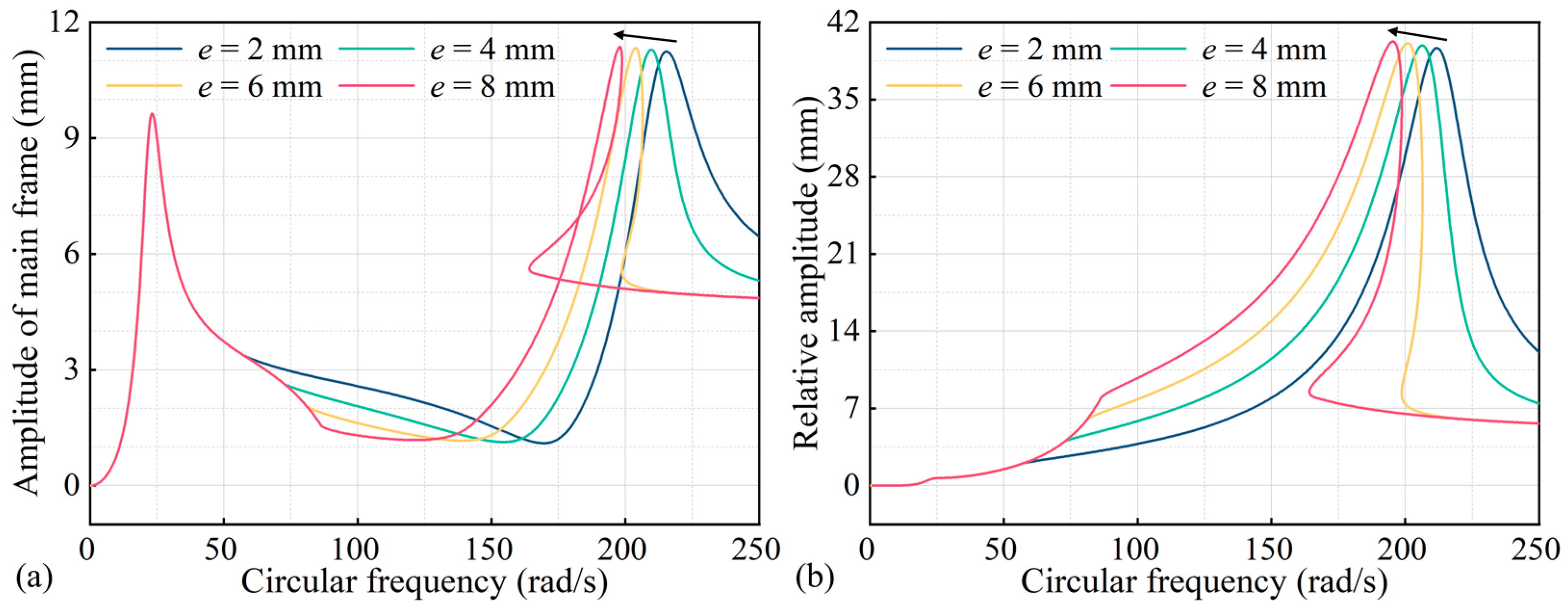
6.1. Effect of Clearance, Stiffness, and Damping of Piecewise Linear Springs on Dynamics of NFFVSs

To investigate the impact of clearance in piecewise linear springs on the dynamics of NFFVSs, the clearance value is varied from 2 mm to 8 mm while keeping other dynamic parameters unchanged. The amplitude–frequency curves of the NFFVS are shown in Figure 12. The clearance in the piecewise linear spring determines the starting frequency of nonlinear vibration in the screen system. When the relative amplitude between the main and floating frames is smaller than the clearance value of the piecewise linear spring, the piecewise linear springs do not contribute to the system’s vibration, resulting in overlapping amplitude–frequency curves for different clearances. However, as the clearance increases, the second resonance frequency of the screen system shifts to the left, and the peak value of the second resonance region increases. The appearance and the widening of the multi-solution zone in the second resonance region are observed with an increase in the clearance value. Due to the appearance of the multi-solution zone, the reasonable operating frequency band for NFFVSs decreases as the clearance value increases. Since the excitation frequency remains constant during the operation of the FFVS, increasing the clearance value of the piecewise linear spring is beneficial for enhancing the relative amplitude of NFFVSs within the reasonable operating frequency region.
Next, the stiffness of the piecewise linear spring is increased from k 2 x to 4.0 times k 2 x while keeping other parameters of the screen system unchanged. Figure 13 illustrates the effects of the spring stiffness on the dynamic response of NFFVSs. The stiffness of the piecewise linear spring primarily influences the dynamic response in the second resonance region of the screen system. As the stiffness increases, the second resonance frequency shifts to the right, the peak value of the resonance region increases, and the multi-solution zone gradually appears and widens. Increasing the stiffness of the piecewise linear spring broadens the operating frequency region for the NFFVS. However, it is important to note that an increase in the spring stiffness results in a decrease in the relative amplitude between the two frames in the operating frequency region.
Furthermore, the effects of damping in the piecewise linear spring on the vibration response of the NFFVS were examined by increasing the damping value from c 2 x to 4.0 times c 2 x , while other parameters of the screen system remained unchanged, as shown in Figure 14. The damping in the piecewise linear spring primarily affects the vibration response in the second resonance region of the screen system. As the damping value increases, the second resonance frequency experiences a slight shift to the left, and the peak value of the resonance region decreases. However, in the anti-resonance region, the amplitude of the main frame increases with higher damping in the piecewise linear spring, while the relative amplitude between the main and floating frames decreases.

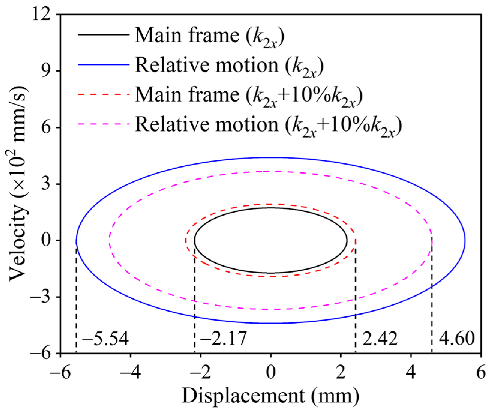
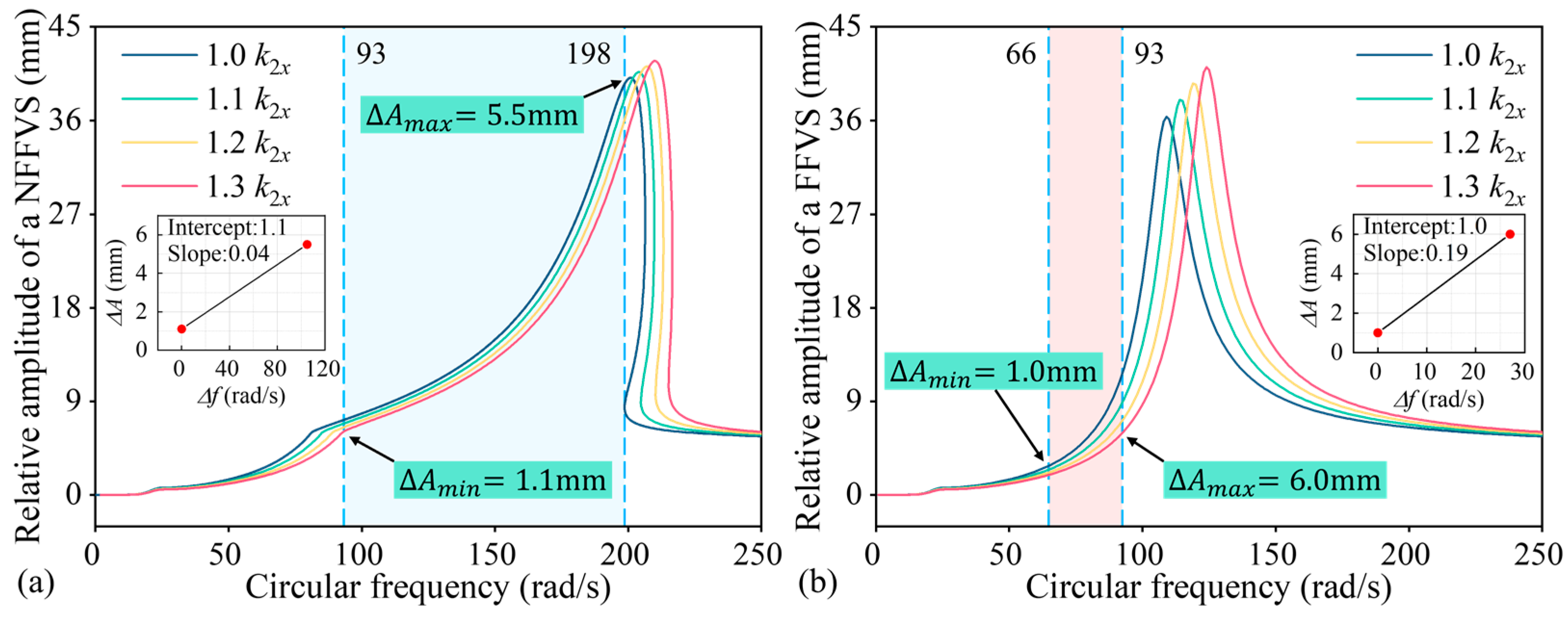
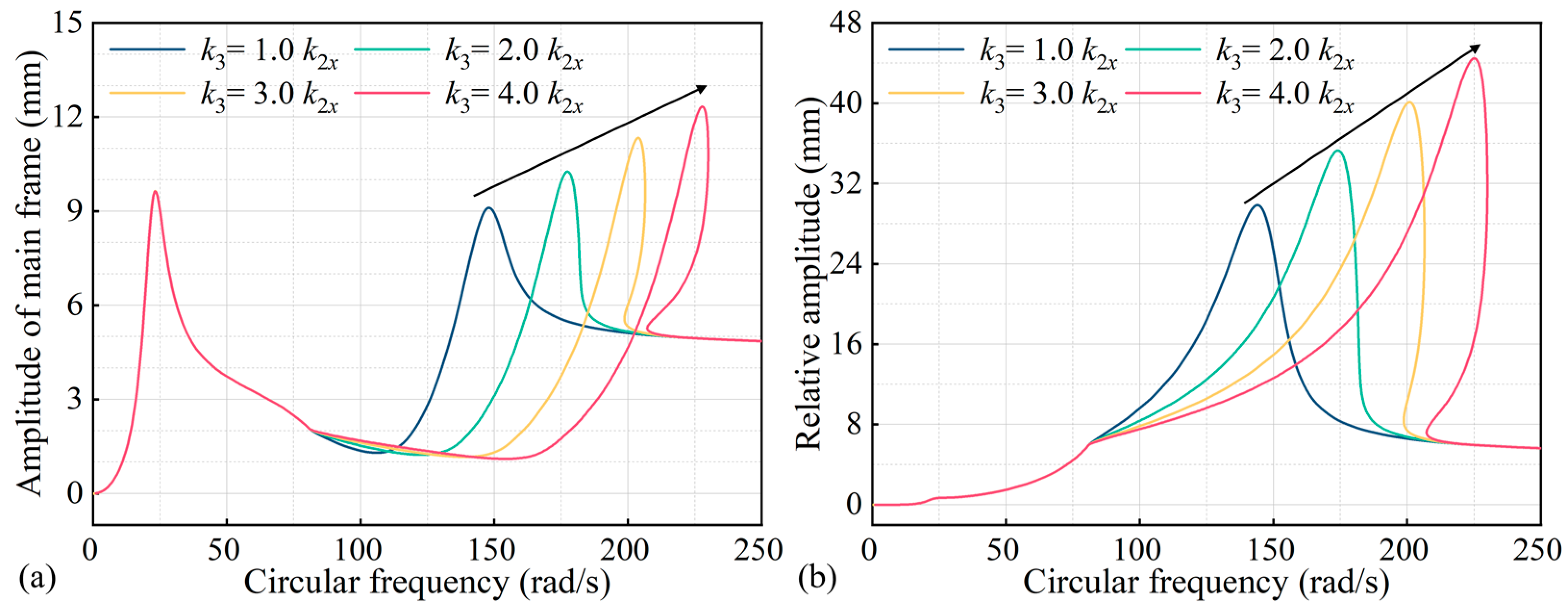
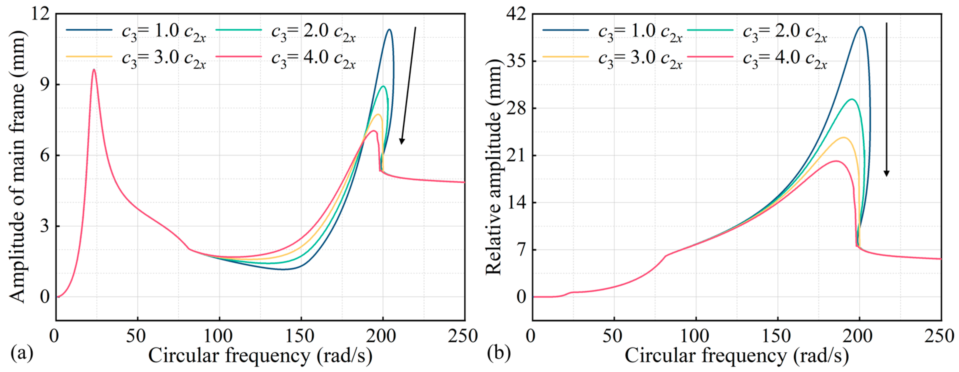
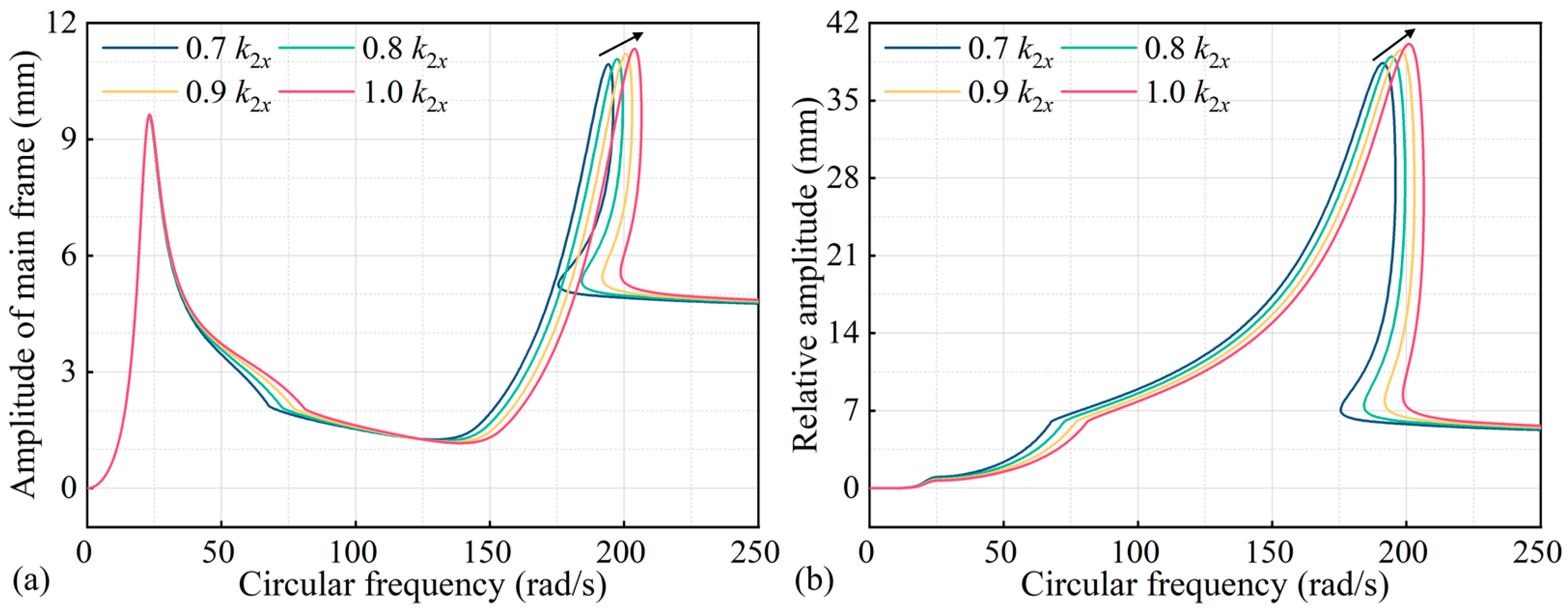
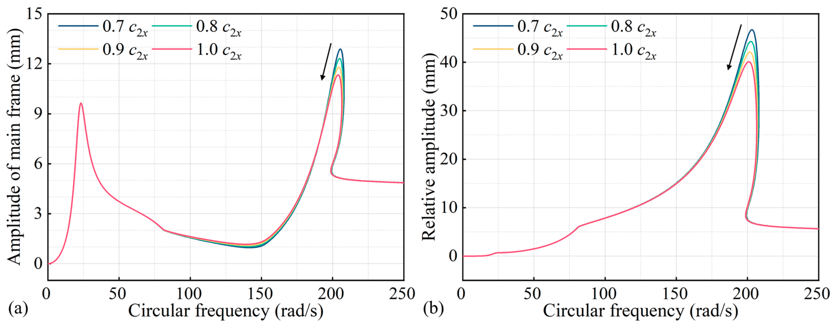
6.2. Effect of Shear Spring Stiffness and Damping on Dynamics of NFFVSs

Figure 15 illustrates the effects of shear spring stiffness on the vibration response of the NFFVS. The stiffness of the shear spring mainly influences the vibration response on the right side of the first resonance region. With an increase in shear spring stiffness, the second resonance frequency of the screen system shifts to the right, and the peak value of the second resonance region is increased. However, a higher shear spring stiffness leads to a reduction in the multi-solution zone of the system, resulting in a decrease in the relative amplitude of the screen system in the operating frequency region. Figure 16 depicts the effects of shear spring damping on the dynamic response of NFFVSs. Shear spring damping mainly affects the dynamic behavior in the second resonance region of the screen system and the anti-resonance region of the main frame. As the shear spring damping increases, the peak value of the second resonance region decreases, and the second resonance frequency undergoes a slight leftward shift. Furthermore, the amplitude of the anti-resonance region in the main frame increases with the higher shear spring damping.

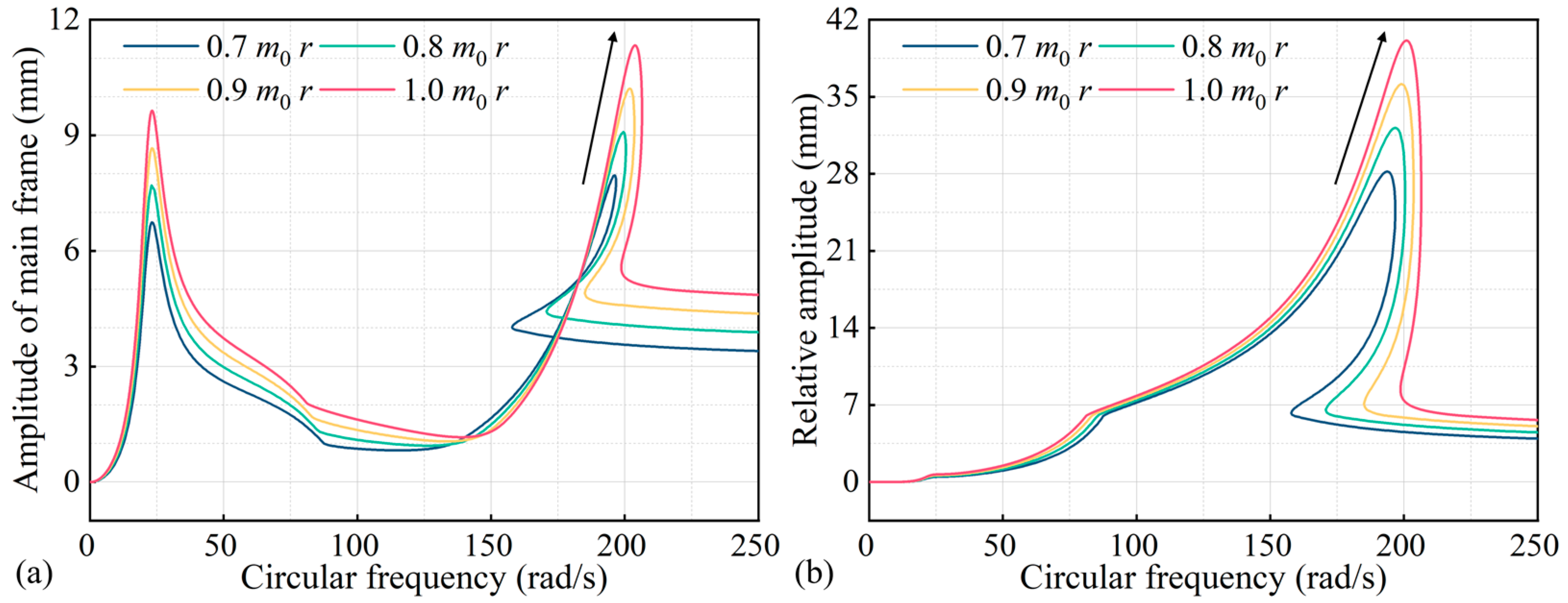
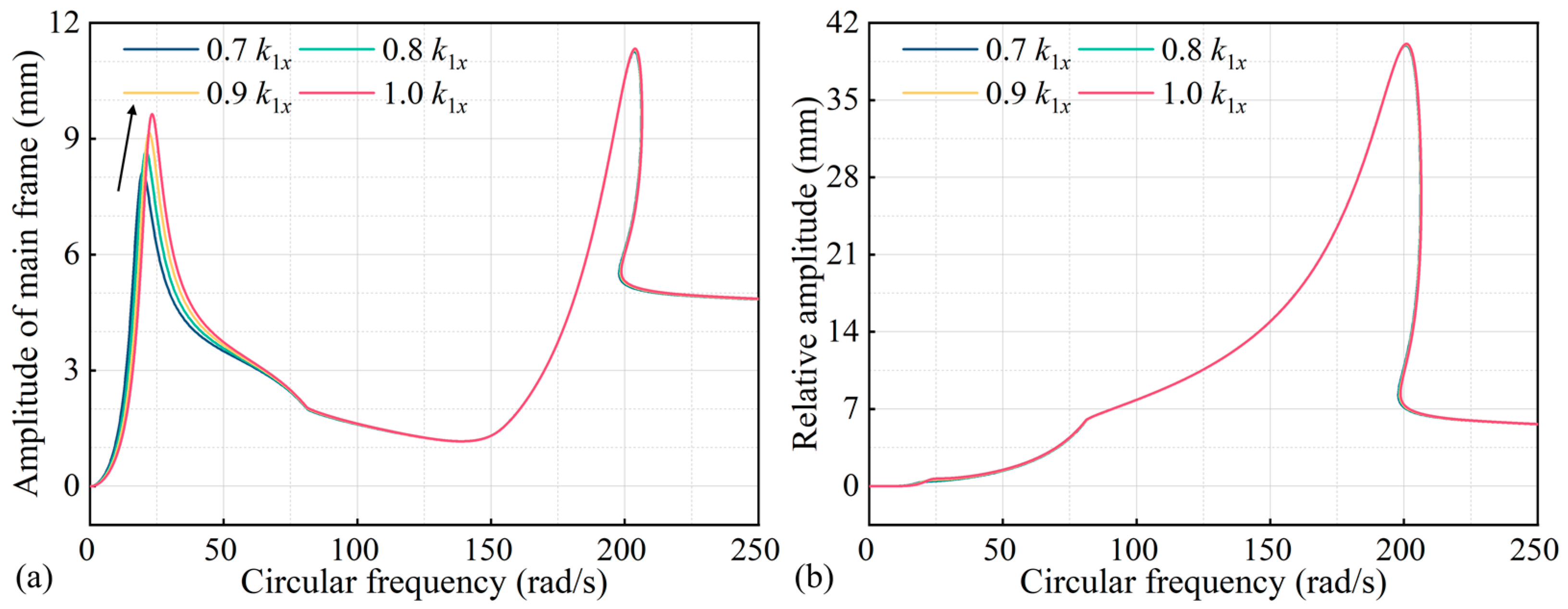
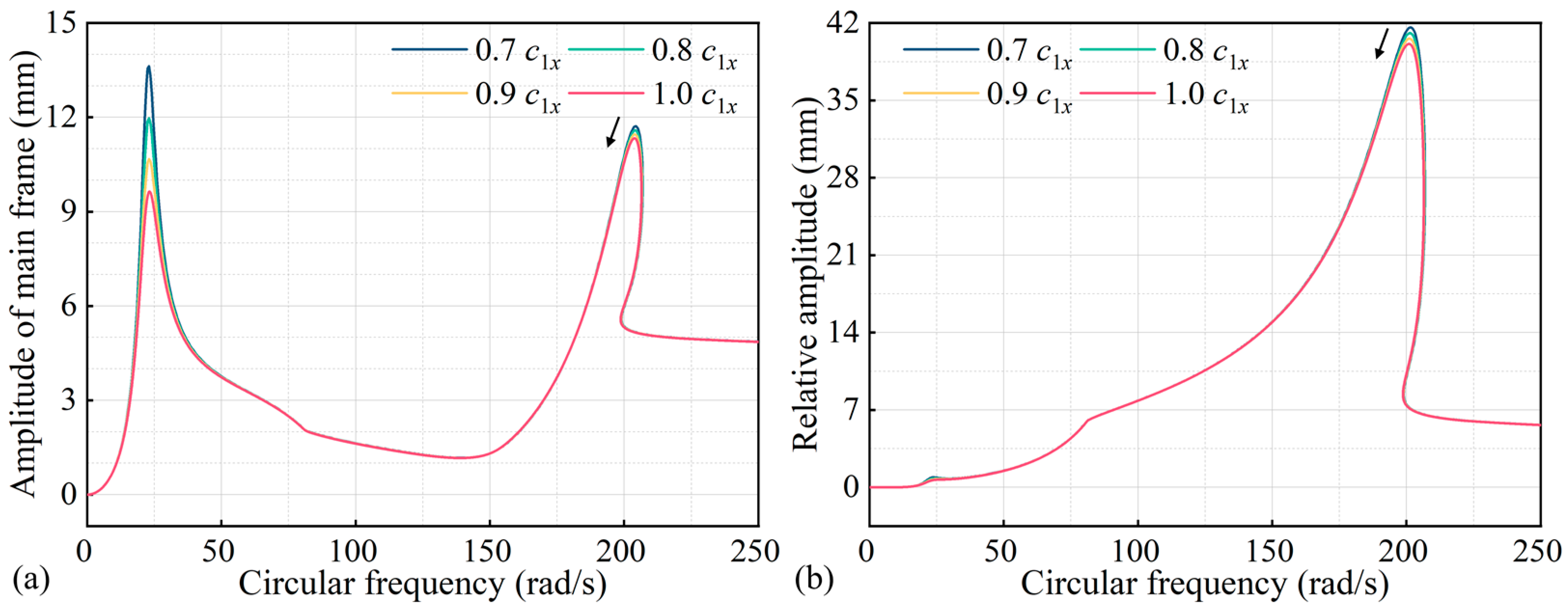
6.3. Effect of Eccentric Mass Moment, Stiffness, and Damping of Isolation Spring on Dynamics of NFFVSs

Figure 17 illustrates the influences of the exciter’s eccentric mass moment on the dynamic response of NFFVSs. The eccentric mass moment was varied from 0.7 to 1.0 times m 0 r , while keeping other dynamic parameters constant. As the eccentric mass moment increases, the second resonance frequency shifts to the right, and the peak value of the second resonance region increases. Increasing the eccentric mass moment leads to a higher relative amplitude between the main and floating frames, reduces the unstable multi-solution zone, and also expands the reasonable operating frequency band for the NFFVS. Figure 18 shows the effects of the stiffness of the isolation spring on the dynamic response of the NFFVS. The stiffness of the isolation spring mainly influences the dynamic response within the first resonance region. As the stiffness of the isolation spring increases, the first resonance frequency shifts to the right, and the peak value of the first resonance region increases. Figure 19 displays the effects of the damping of the isolation spring on the dynamic response of the NFFVS. The damping of the isolation spring mainly affects the peak amplitude value of the first and second resonance regions. With an increase in the damping of the isolation spring, the peak values of the first and second resonance regions of the screen system decrease.

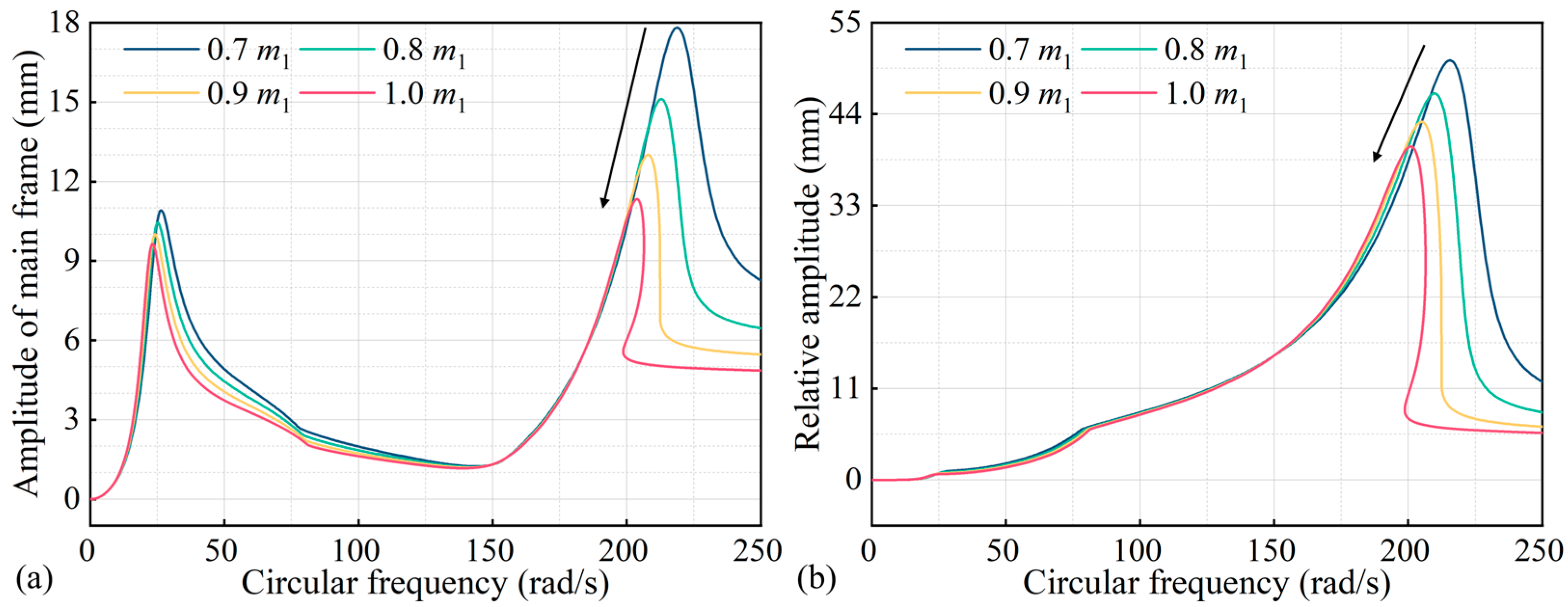
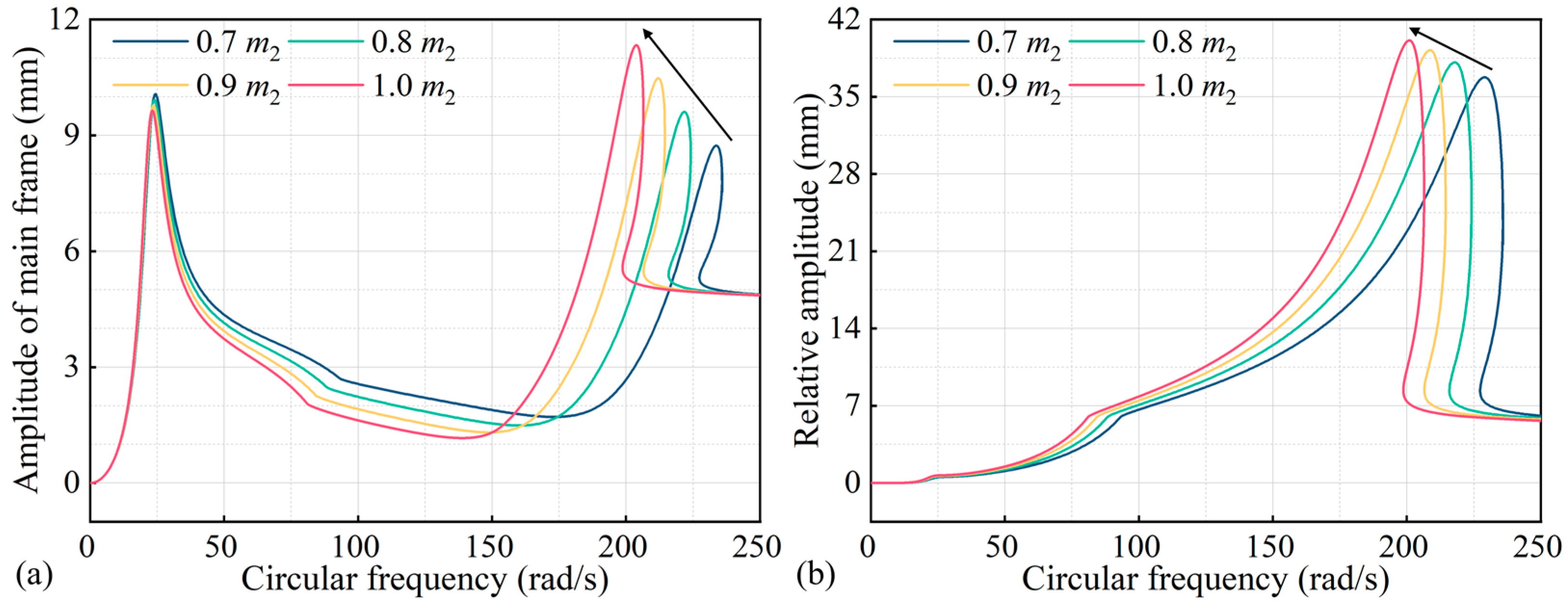
6.4. Effect of Mass of Main and Floating Frames on Dynamics of NFFVSs

Figure 20 presents the effects of the mass of the main frame on the dynamic response of the NFFVS. The mass of the main screen frame was varied from 0.7 to 1.0 times m 1 , while the other parameters remained unchanged. The mass of the main frame mainly influences the dynamic response in the resonance regions. With an increase in the mass of the main frame, both the first resonance frequency and the second resonance frequency shift to the left, and the peak amplitude value of the resonance regions decreases. Increasing the mass of the main frame widens the unstable multi-solution zone and narrows the operating frequency region. Figure 21 shows the effects of the mass of the floating frame on the dynamic response of the NFFVS. As the mass of the floating screen frame increases, both the first and second resonance frequencies shift to the left. Additionally, the peak amplitude value of the first resonance region of the main frame decreases, while the peak amplitude value of the second resonance increases. Increasing the mass of the floating frame in the reasonable operating frequency region can enhance the relative amplitude between the main and floating frames.

7. Conclusions

This paper investigated the introduction of piecewise linear springs to stabilize the vibration amplitude of a flip-flow vibrating screen (FFVS), i.e., to minimize the change in the vibration amplitudes of the main and the floating frames after the processed materials are loaded onto the vibrating screen. First, the operating frequency region for FFVS was optimized using Sobol’s method of global sensitivity analysis. This analysis revealed that the relative amplitude between the main and floating frames is variable when the materials are loaded. Second, the operating frequency region and dynamics of the nonlinear flip-flow vibrating screen (NFFVS) with piecewise linear springs were studied by employing both the harmonic balance method (HBM) and the Runge–Kutta method. A test-rig with nonlinear stiffness feature was constructed to perform experiments, to validate the theoretical findings. Finally, the effects of system parameters on the dynamic response of the NFFVS were investigated through theoretical analysis. Based on the analysis, the following conclusions can be drawn:
The operating frequency region for the FFVS lies between the equal amplitude frequency ω e a and the anti-resonance frequency ω a r . For the NFFVS with piecewise linear springs, the operating frequency region ranges from the critical frequency ω c s to the frequency ω l b , corresponding to the saddle-node bifurcation point. The introduction of piecewise linear springs could effectively stabilize the amplitude of the flip-flow screen during the screening process.
Increasing the eccentric mass moment can not only enhance the relative amplitude of the NFFVS in the operating frequency region but also broaden the operating frequency region for the NFFVS. Additionally, increasing the clearance of the piecewise linear spring and mass of the floating frame, as well as reducing the stiffness of the piecewise linear spring and shear spring, can enhance the relative amplitude of the NFFVS in the operating frequency region. On the contrary, reducing the clearance of the piecewise linear spring and mass of the floating frame, as well as increasing the stiffness of the piecewise linear spring and shear spring, can broaden the operating frequency region for the NFFVS.
Through understanding how piecewise linear springs can effectively stabilize the amplitude of the flip-flow screen, this paper has provided valuable insights for optimizing the operating frequency region and dynamics of the NFFVS, offering guidelines for the design and improvement of flip-flow vibrating screens.

Author Contributions

Conceptualization, D.L.; methodology, D.L.; software, D.L.; validation, D.L.; formal analysis, D.L. and N.X.; investigation, D.L.; resources, D.L. and X.W.; data curation, D.L.; writing—original draft preparation, D.L.; writing—review and editing, D.L.; visualization, D.L., W.Z. and Z.L.; supervision, X.W.; project administration, X.W.; funding acquisition, X.W. and D.L. All authors have read and agreed to the published version of the manuscript.

Funding

This work was supported by the China Scholarship Council [202106430037] and the Anhui Province Major Science and Technology Achievements Engineering Research and Development Special Project [202103c08020007].

Data Availability Statement

The data presented in this study are available on request from the corresponding author due to the external policy.

Acknowledgments

The first author sincerely appreciate J.C. Ji, Keisuke Yamada and Youcheng Zeng for their assistance.

Conflicts of Interest

The authors declare no conflicts of interest.

References

  1. Zhang, K.; Chen, T.N.; He, L. Damping behaviors of granular particles in a vertically vibrated closed container. Powder Technol. 2017, 321, 173–179. [Google Scholar] [CrossRef]
  2. Guo, H.H.; Ichikawa, K.; Sakai, H.; Zhang, H.; Zhang, X.P.; Tsuruta, K.; Makihara, K.; Takezawa, A. Numerical and experimental analysis of additively manufactured particle dampers at low frequencies. Powder Technol. 2022, 396, 696–709. [Google Scholar] [CrossRef]
  3. Dong, K.J.; Shinohara, K.; Ohyama, Y.; Yu, A.B. Particle dispersion in a horizontally vibrating vessel under microgravity. Powder Technol. 2015, 269, 55–65. [Google Scholar] [CrossRef]
  4. Yu, S.J.; Li, S.J.; Guo, P.; Zhang, Y.L.; Li, W.H.; Wang, H.; Shi, W.; Jiang, H.S.; Duan, C.L. Research on highly efficient quality improvement process and product blending scheme for fine coal. Powder Technol. 2023, 430, 119011. [Google Scholar] [CrossRef]
  5. Liu, X.Y.; Zheng, Q.J.; Yang, L.; Cai, M.Y.; Cheng, G.J.; Yu, A.B. The segregation of cement clinker particles in a mill-feeding hopper: PIV experiment and FEM modelling. Powder Technol. 2023, 426, 118656. [Google Scholar] [CrossRef]
  6. Bak, L.; Noga, S.; Skrzat, A.; Stachowicz, F. Dynamic analysis of vibrating screener system. In Proceedings of the International Symposium on Dynamic Deformation and Fracture of Advanced Materials, Loughborough, UK, 9–11 September 2013. [Google Scholar]
  7. Soni, R.K.; Jaiswal, S.; Dash, S.; Eswaraiah, C. CFD and DEM numerical modelling of industrial vibrating desliming screen for performance optimization and minimal misplacement. Powder Technol. 2023, 426, 118630. [Google Scholar] [CrossRef]
  8. Moraes, M.N.; Galery, R.; Mazzinghy, D.B. A review of process models for wet fine classification with high frequency screens. Powder Technol. 2021, 394, 525–532. [Google Scholar] [CrossRef]
  9. Bak, L.; Noga, S.; Stachowicz, F. The experimental investigation of the screen operation in the parametric resonance conditions. Acta Mech. Autom. 2015, 9, 191–194. [Google Scholar]
  10. Bak, L.; Noga, S.; Stachowicz, F. Modelling and numerical simulation of parametric resonance phenomenon in vibrating screen. Vib. Phys. Syst. 2016, 27, 35–40. [Google Scholar]
  11. Arifuzzaman, S.M.; Dong, K.J.; Yu, A.B. Process model of vibrating screen based on DEM and physics-informed machine learning. Powder Technol. 2022, 410, 117869. [Google Scholar] [CrossRef]
  12. Yu, C.; Pu, K.W.; Geng, R.H.; Qiao, D.Z.; Lin, D.D.; Xu, N.N.; Wang, X.W.; Li, J.W.; Gong, S.P.; Zhou, Q. Comparison of flip-flow screen and circular vibrating screen vibratory sieving processes for sticky fine particles. Miner. Eng. 2022, 87, 107791. [Google Scholar] [CrossRef]
  13. Zhao, G.F.; Pu, K.W.; Xu, N.N.; Gong, S.P.; Wang, X.W. Simulation of particles motion on a double vibrating flip-flow screen surface based on FEM and DEM coupling. Powder Technol. 2023, 421, 118422. [Google Scholar] [CrossRef]
  14. Li, H.X.; Liu, C.S.; Shen, L.; Zhao, L.L.; Li, S. Kinematics characteristics of the flip-flow screen with a crankshaft-link structure and screening analysis for moist coal. Powder Technol. 2021, 394, 326–335. [Google Scholar] [CrossRef]
  15. Duan, C.L.; Yuan, J.L.; Pan, M.; Huang, T.; Jiang, H.S.; Zhao, Y.M.; Qiao, J.P.; Wang, W.N.; Yu, S.J.; Lu, J.W. Variable elliptical vibrating screen: Particles kinematics and industrial application. Int. J. Min. Sci. Technol. 2021, 31, 1013–1022. [Google Scholar] [CrossRef]
  16. Xiong, X.Y.; Niu, L.K.; Gu, C.X.; Wang, Y.H. Vibration characteristics of an inclined flip-flow screen panel in banana flip-flow screen panel in banana flip-flow screens. J. Sound Vib. 2017, 411, 108–128. [Google Scholar] [CrossRef]
  17. Lin, D.D.; Ji, J.C.; Yu, C.; Wang, X.W.; Xu, N.N. A non-linear model of screen panel for dynamics analysis of a flip-flow vi-brating screen. Powder Technol. 2023, 418, 118312. [Google Scholar] [CrossRef]
  18. Yu, C.; Wang, X.W.; Gong, S.P.; Pang, K.F.; Zhao, G.F.; Zhou, Q.; Lin, D.D.; Xu, N.N. Stability analysis of the screening process of a vibrating flip-flow screen. Miner. Eng. 2021, 163, 106794. [Google Scholar] [CrossRef]
  19. Lin, D.D.; Ji, J.C.; Wang, X.W.; Wang, Y.X.; Xu, N.N.; Ni, Q.; Zhao, G.F.; Feng, K. A rigid-flexible coupled dynamic model of a flip-flow vibrating screen considering the effects of processed materials. Powder Technol. 2023, 427, 118753. [Google Scholar] [CrossRef]
  20. Fazekas, B.; Goda, T.J. Constitutive modelling of rubbers: Mullins effect, residual strain, time-temperature dependence. Int. J. Mech. Sci. 2021, 210, 106735. [Google Scholar] [CrossRef]
  21. Luo, R.; Shi, H.L.; Guo, J.Y.; Huang, L.; Wang, J. A nonlinear rubber spring model for the dynamic simulation of a high-speed train. Veh. Syst. Dyn. 2020, 58, 1367–1384. [Google Scholar] [CrossRef]
  22. Nayek, R.; Abdessalem, A.B.; Dervilis, N.; Cross, E.J.; Worden, K. Identification of piecewise-linear mechanical oscillators via Bayesian model selection and parameter estimation. Mech. Syst. Signal Process. 2023, 196, 110300. [Google Scholar] [CrossRef]
  23. Wang, S.; Hua, L.; Yang, C.; Zhang, Y.O.; Tan, X.D. Nonlinear vibrations of a piecewise-linear quarter-car truck model by incremental harmonic balance method. Nonlinear Dynam. 2018, 92, 1719–1732. [Google Scholar] [CrossRef]
  24. Alzubaidi, B.; Nemeth, R.K. Modal analysis-based calculation of periodic nonlinear responses of harmonically forced piecewise linear elastic systems. J. Sound Vib. 2023, 549, 117576. [Google Scholar] [CrossRef]
  25. Ranjbarzadeh, H.; Kakavand, F. Determination of nonlinear vibration of 2DOF system with an asymmetric piecewise-linear compression spring using incremental harmonic balance method. Eur. J. Mech. A-Solid. 2019, 73, 161–168. [Google Scholar] [CrossRef]
  26. Wang, X.; Geng, X.F.; Mao, X.Y.; Ding, H.; Jing, X.J.; Chen, L.Q. Theoretical and experimental analysis of vibration reduction for piecewise linear system by nonlinear energy sink. Mech. Syst. Signal Process. 2022, 172, 109001. [Google Scholar] [CrossRef]
  27. Yao, H.L.; Cao, Y.B.; Ding, Z.Y.; Wen, B.C. Using grounded nonlinear energy sinks to suppress lateral vibration in rotor systems. Mech. Syst. Signal Process. 2019, 124, 237–253. [Google Scholar] [CrossRef]
  28. Geng, X.F.; Ding, H.; Mao, X.Y.; Chen, L.Q. Nonlinear energy sink with limited vibration amplitude. Mech. Syst. Signal Process. 2021, 156, 107625. [Google Scholar] [CrossRef]
  29. Londono, J.M.; Cooper, J.E.; Neild, S.A. Identification of systems containing nonlinear stiffnesses using backbone curves. Mech. Syst. Signal Process. 2017, 84, 116–135. [Google Scholar] [CrossRef]
  30. Wang, J.D.; Liu, X.T.; Zhou, X.B.; Lu, G.P.; Zhang, Z.Y. Performance of a launch isolator: Theoretical and experimental study. J. Sound Vib. 2020, 483, 115487. [Google Scholar] [CrossRef]
Figure 1. Schematic of the structure and working principle of a flip-flow vibrating screen (FFVS): (a) structure, (b) working principle.
Minerals 14 00406 g001
Figure 2. Dynamics of an FFVS: (a) mechanical model, (b) mathematical model, (c) amplitude-frequency response.
Minerals 14 00406 g002
Figure 3. Global sensitivity analysis of dynamic parameters of an FFVS.
Minerals 14 00406 g003
Figure 4. Effect of loading materials on the phase portraits of the vibrations of the main and the floating frames.
Minerals 14 00406 g004
Figure 5. Dynamic model of a nonlinear flip-flow vibrating screen (NFFVS).
Minerals 14 00406 g005
Figure 6. Fitting results of the hyperbolic tangent function to the piecewise function under three conditions.
Minerals 14 00406 g006
Figure 7. Amplitude–frequency response of NFFVSs.
Minerals 14 00406 g007
Figure 8. Comparison of loading dynamics between the NFFVS and FFVS.
Minerals 14 00406 g008
Figure 9. Two-mass clearance nonlinear test-rig and experimental setup: (a) schematic diagram of the test-rig, (b) piecewise linear spring, (c) experimental system.
Minerals 14 00406 g009
Figure 10. Comparison between the experimental results and theoretical analysis of nonlinear vibration of NFFVS.
Minerals 14 00406 g010
Figure 11. Time history of the displacement of the jump phenomenon in the multi-solution zone.
Minerals 14 00406 g011
Figure 12. Effects of piecewise linear spring clearance on the vibration amplitude of the NFFVS.
Minerals 14 00406 g012
Figure 13. Effects of piecewise linear spring stiffness on the vibration amplitude of the NFFVS.
Minerals 14 00406 g013
Figure 14. Effects of piecewise linear spring damping on the vibration amplitude of the NFFVS.
Minerals 14 00406 g014
Figure 15. Effects of shear spring stiffness on the vibration response of the NFFVS.
Minerals 14 00406 g015
Figure 16. Effects of shear spring damping on the vibration response of the NFFVS.
Minerals 14 00406 g016
Figure 17. Effects of eccentric mass moment on the dynamics of the NFFVS.
Minerals 14 00406 g017
Figure 18. Effects of isolation spring stiffness on the dynamics of the NFFVS.
Minerals 14 00406 g018
Figure 19. Effects of isolation spring damping on the dynamics of the NFFVS.
Minerals 14 00406 g019
Figure 20. Effects of the main frame mass on the dynamic response of the NFFVS.
Minerals 14 00406 g020
Figure 21. Effects of the floating frame mass on the dynamic response of the NFFVS.
Minerals 14 00406 g021
Table 1. Parameter ranges for sensitivity analysis of an FFVS.
VariablesMeanMinimumMaximum
m1 (kg)916.000870.200961.800
m2 (kg)310.000294.500325.500
m0r (kg·mm)4168.2513959.8384376.664
k1x (kN/m)630.000598.500661.500
c1x (kN·s/m)9.8669.37310.359
k2x (kN/m)2700.0002565.0002835.000
c2x (kN·s/m)2.6052.4752.735
Disclaimer/Publisher’s Note: The statements, opinions and data contained in all publications are solely those of the individual author(s) and contributor(s) and not of MDPI and/or the editor(s). MDPI and/or the editor(s) disclaim responsibility for any injury to people or property resulting from any ideas, methods, instructions or products referred to in the content.

