Author Contributions
Conceptualization, Q.W. and G.L.; methodology, Q.W. and Q.L.; software, Q.L.; validation, Q.W.; formal analysis, Q.W.; investigation, S.M.; resources, G.L.; data curation, Q.W.; writing—original draft preparation, Q.W.; writing—review and editing, G.L., R.T. and S.M.; visualization, Q.W.; supervision, R.T.; project administration, R.T.; funding acquisition, R.T. All authors have read and agreed to the published version of the manuscript.
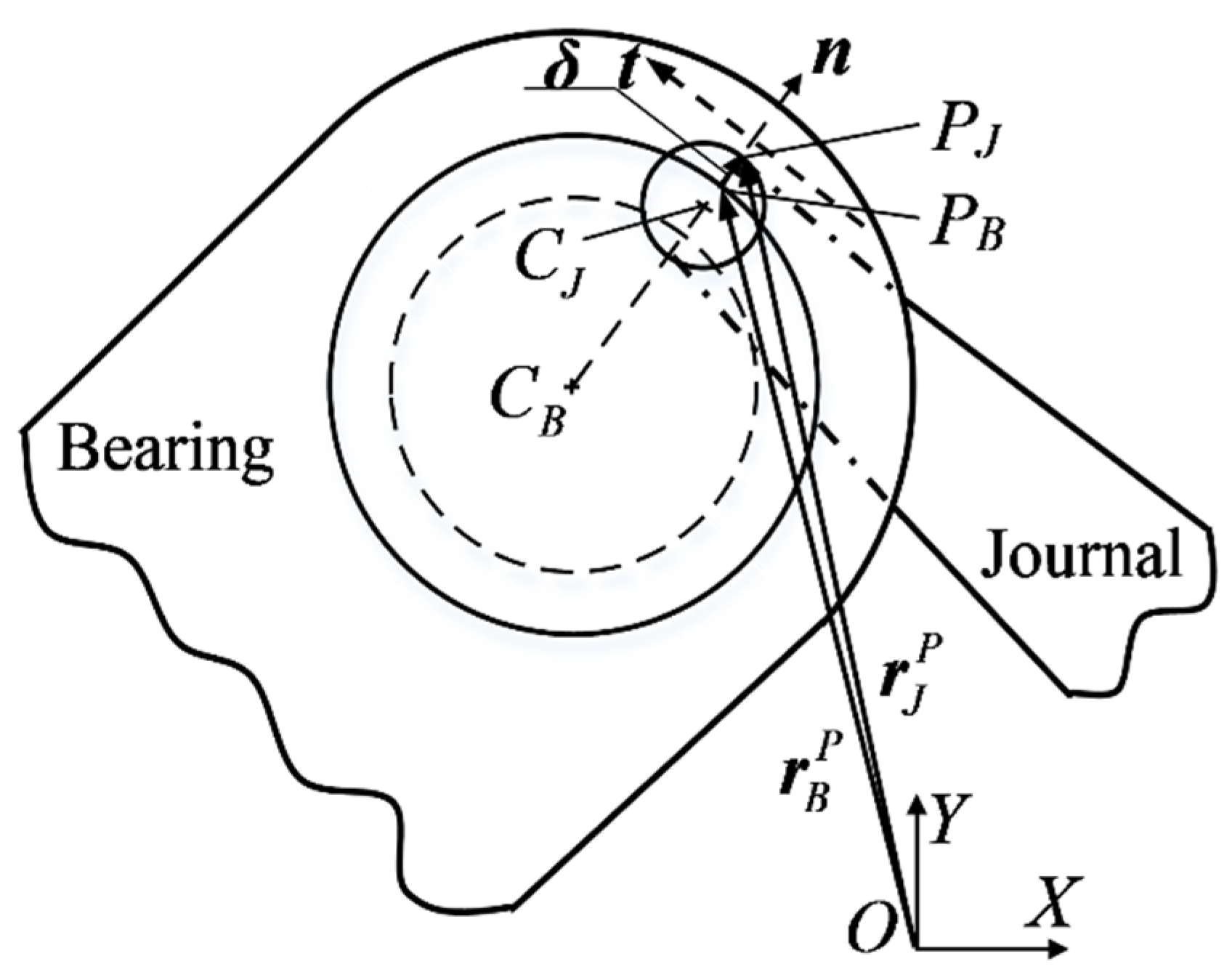
Figure 1.
Clearance joint model.
Figure 1.
Clearance joint model.
Figure 2.
Collision model at the clearance joint.
Figure 2.
Collision model at the clearance joint.
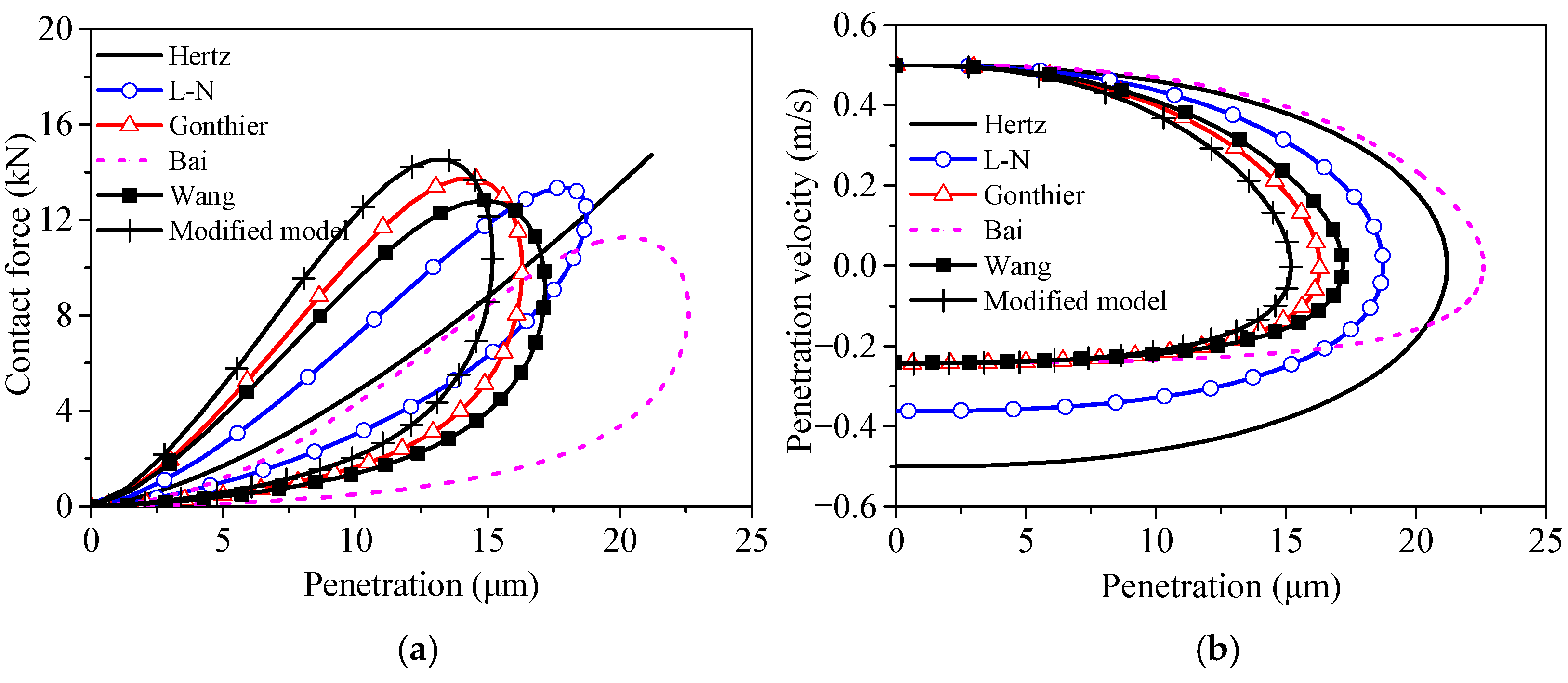
Figure 3.
Dynamic responses based on the six models: (a) contact force; (b) penetration velocity.
Figure 3.
Dynamic responses based on the six models: (a) contact force; (b) penetration velocity.
Figure 4.
The test rig of the mechanism [
29].
Figure 4.
The test rig of the mechanism [
29].
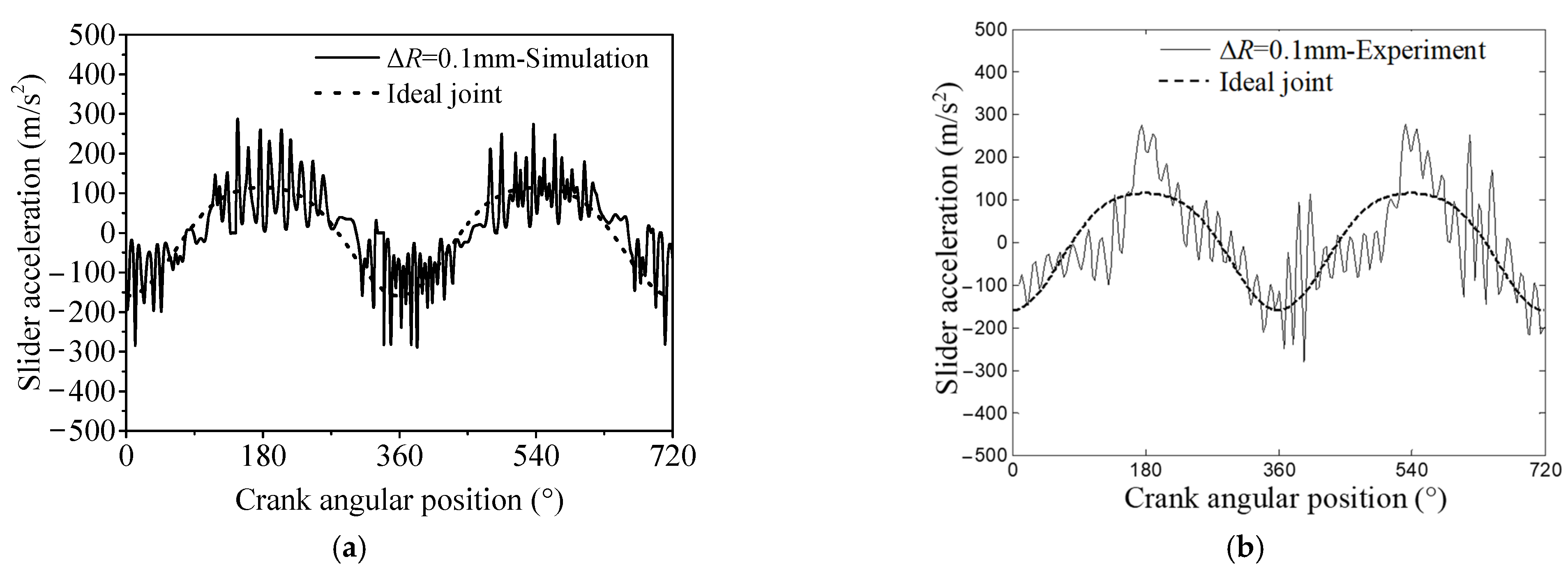
Figure 5.
Comparison results of the slider acceleration with clearance sizes defining as 0.1, 0.3, 0.5 mm respectively: (
a,
c,
e) simulations; (
b,
d,
f) experiments [
29].
Figure 5.
Comparison results of the slider acceleration with clearance sizes defining as 0.1, 0.3, 0.5 mm respectively: (
a,
c,
e) simulations; (
b,
d,
f) experiments [
29].
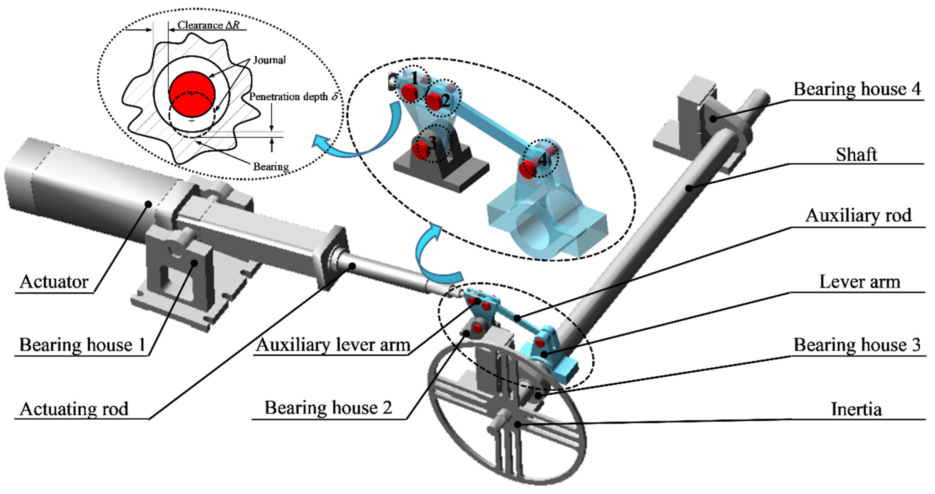
Figure 6.
Dynamic model of a rigid flap actuation system with four clearance joins.
Figure 6.
Dynamic model of a rigid flap actuation system with four clearance joins.
Figure 7.
Angle of the rigid system with different clearance sizes: (a) angle; (b) partial enlarged drawing.
Figure 7.
Angle of the rigid system with different clearance sizes: (a) angle; (b) partial enlarged drawing.
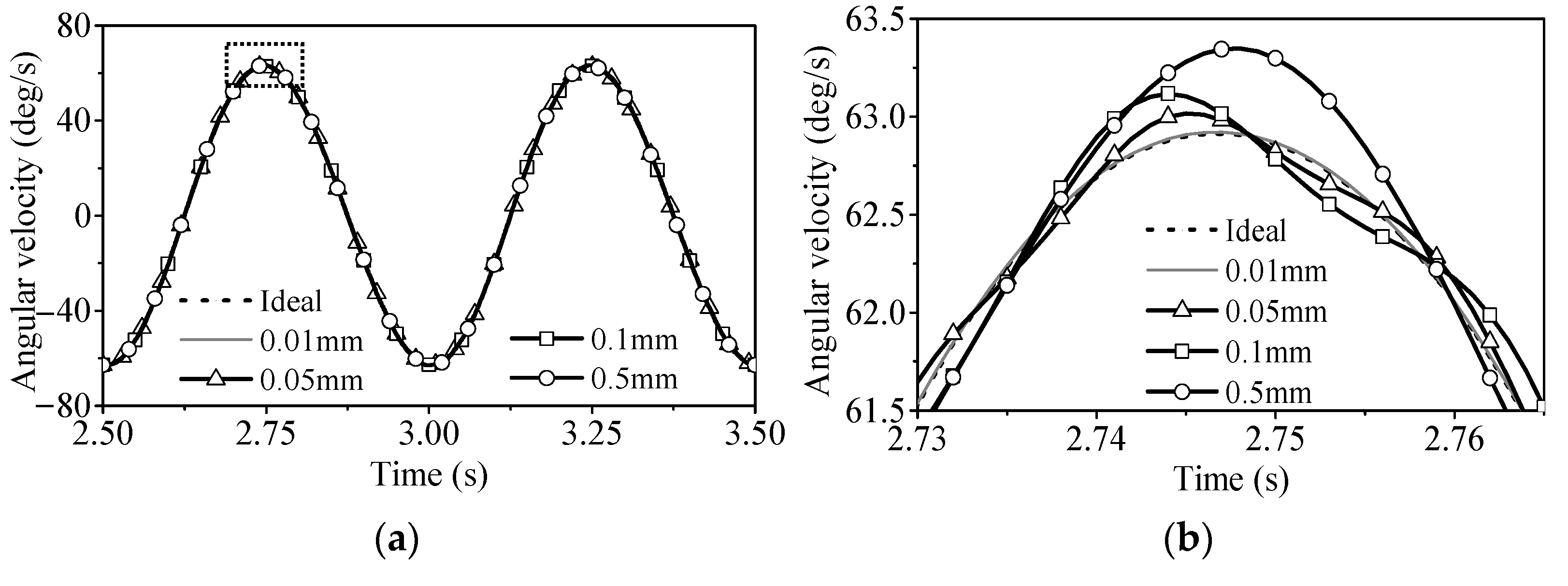
Figure 8.
Angular velocity of the rigid system with different clearance sizes: (a) angular velocity; (b) partial enlarged drawing.
Figure 8.
Angular velocity of the rigid system with different clearance sizes: (a) angular velocity; (b) partial enlarged drawing.
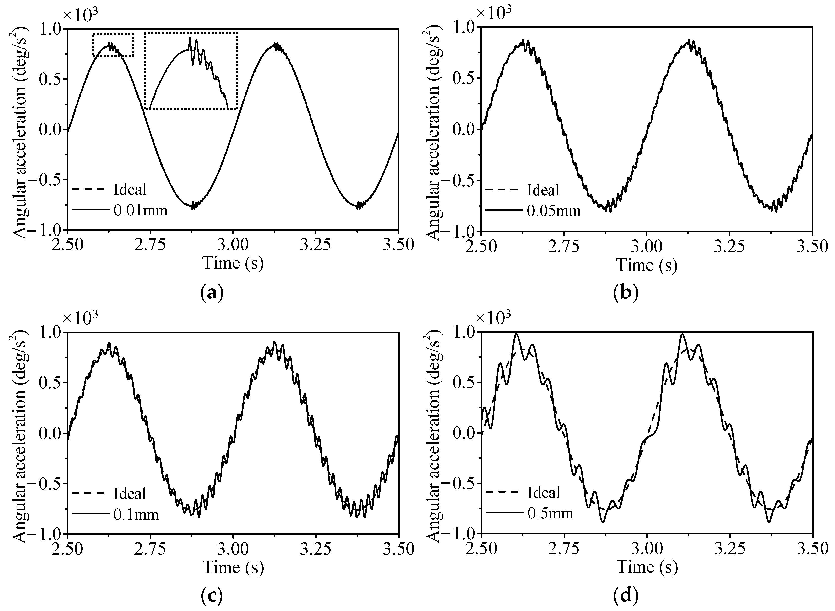
Figure 9.
Angular acceleration of the rigid system with different clearance sizes: (a–d) clearance size = 0.01/0.05/0.10/0.50 mm.
Figure 9.
Angular acceleration of the rigid system with different clearance sizes: (a–d) clearance size = 0.01/0.05/0.10/0.50 mm.
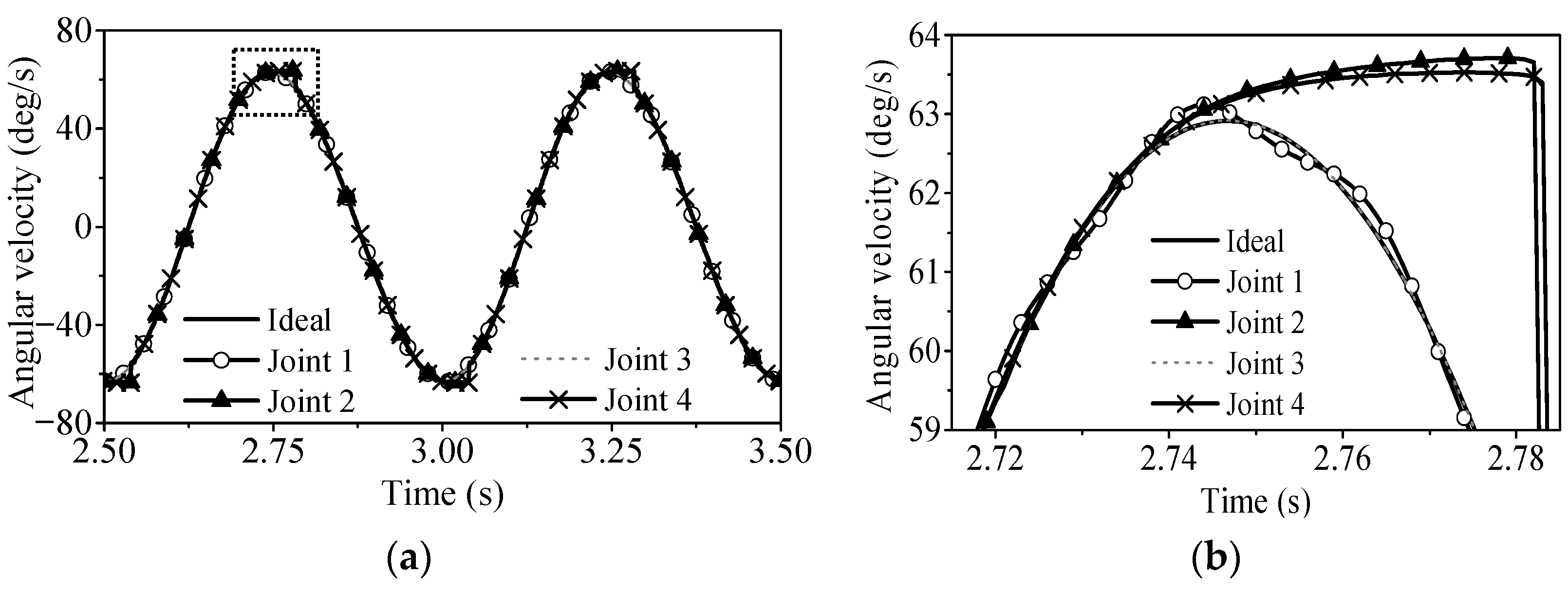
Figure 10.
Angular velocity of the rigid system with different clearance joint position: (a) angular velocity; (b) partial enlarged drawing.
Figure 10.
Angular velocity of the rigid system with different clearance joint position: (a) angular velocity; (b) partial enlarged drawing.
Figure 11.
Angular acceleration of the rigid system with different clearance joint position: (a–d) joints 1,2,3,4.
Figure 11.
Angular acceleration of the rigid system with different clearance joint position: (a–d) joints 1,2,3,4.
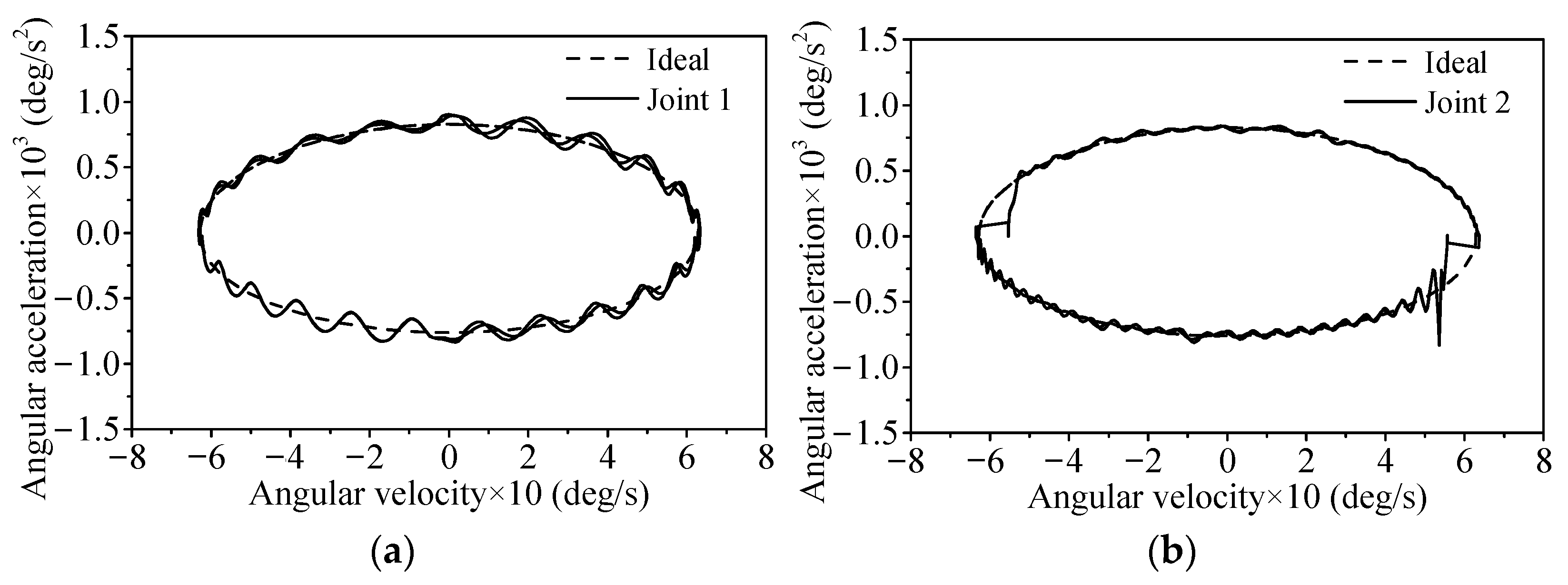
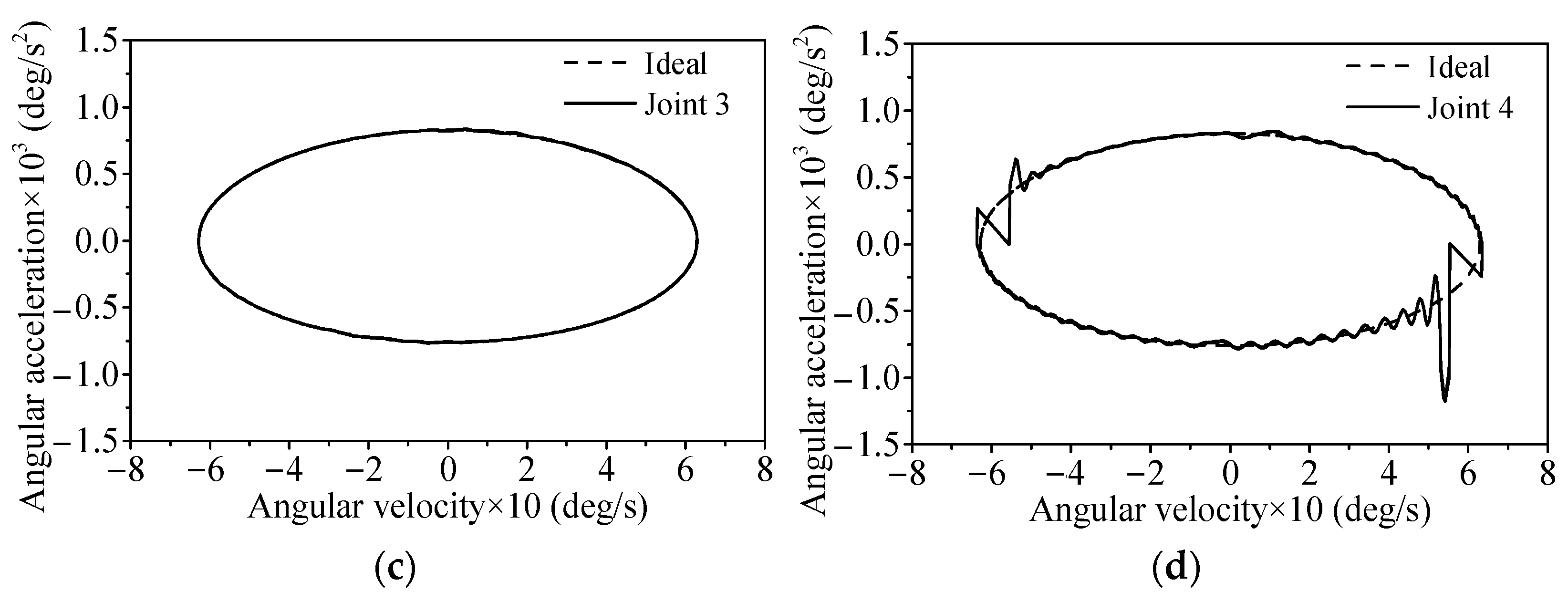
Figure 12.
Angular acceleration-angular velocity phase diagram of the rigid system with different clearance joint position: (a–d) joints 1,2,3,4.
Figure 12.
Angular acceleration-angular velocity phase diagram of the rigid system with different clearance joint position: (a–d) joints 1,2,3,4.
Figure 13.
Finite element model of flexible auxiliary lever arm and modal diagrams of the first five modes: (a) finite element model; (b–f) first to fifth modes.
Figure 13.
Finite element model of flexible auxiliary lever arm and modal diagrams of the first five modes: (a) finite element model; (b–f) first to fifth modes.
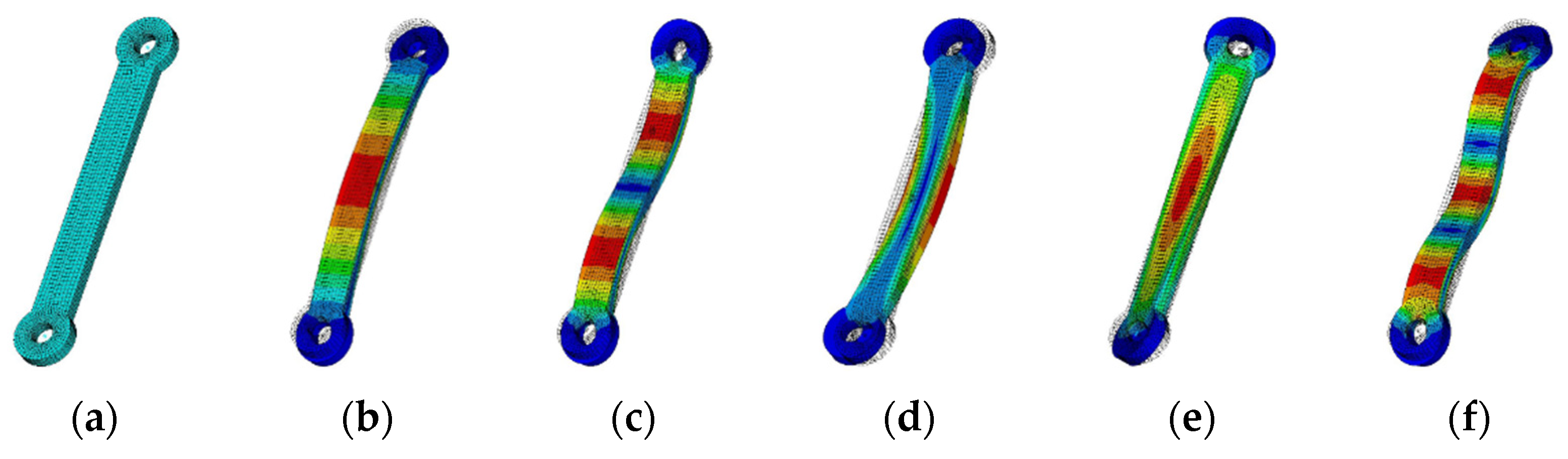
Figure 14.
Finite element model of flexible auxiliary rod and modal diagrams of the first five modes: (a) finite element model; (b–f) first to fifth modes.
Figure 14.
Finite element model of flexible auxiliary rod and modal diagrams of the first five modes: (a) finite element model; (b–f) first to fifth modes.
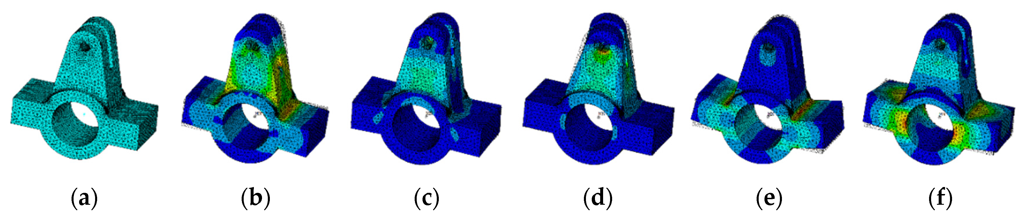
Figure 15.
Finite element model of flexible lever arm and modal diagrams of the first five modes: (a) finite element model; (b–f) first to fifth modes.
Figure 15.
Finite element model of flexible lever arm and modal diagrams of the first five modes: (a) finite element model; (b–f) first to fifth modes.
Figure 16.
Angular velocity of the rigid-flexible system with different flexible body number when considering a single clearance joint: (a) angular velocity; (b) partial enlarged drawing.
Figure 16.
Angular velocity of the rigid-flexible system with different flexible body number when considering a single clearance joint: (a) angular velocity; (b) partial enlarged drawing.
Figure 17.
Angular acceleration of the rigid-flexible flap actuation system with different flexible body number when considering a single clearance joint: (a) angular acceleration; (b,c) partial enlarged drawings 1,2.
Figure 17.
Angular acceleration of the rigid-flexible flap actuation system with different flexible body number when considering a single clearance joint: (a) angular acceleration; (b,c) partial enlarged drawings 1,2.
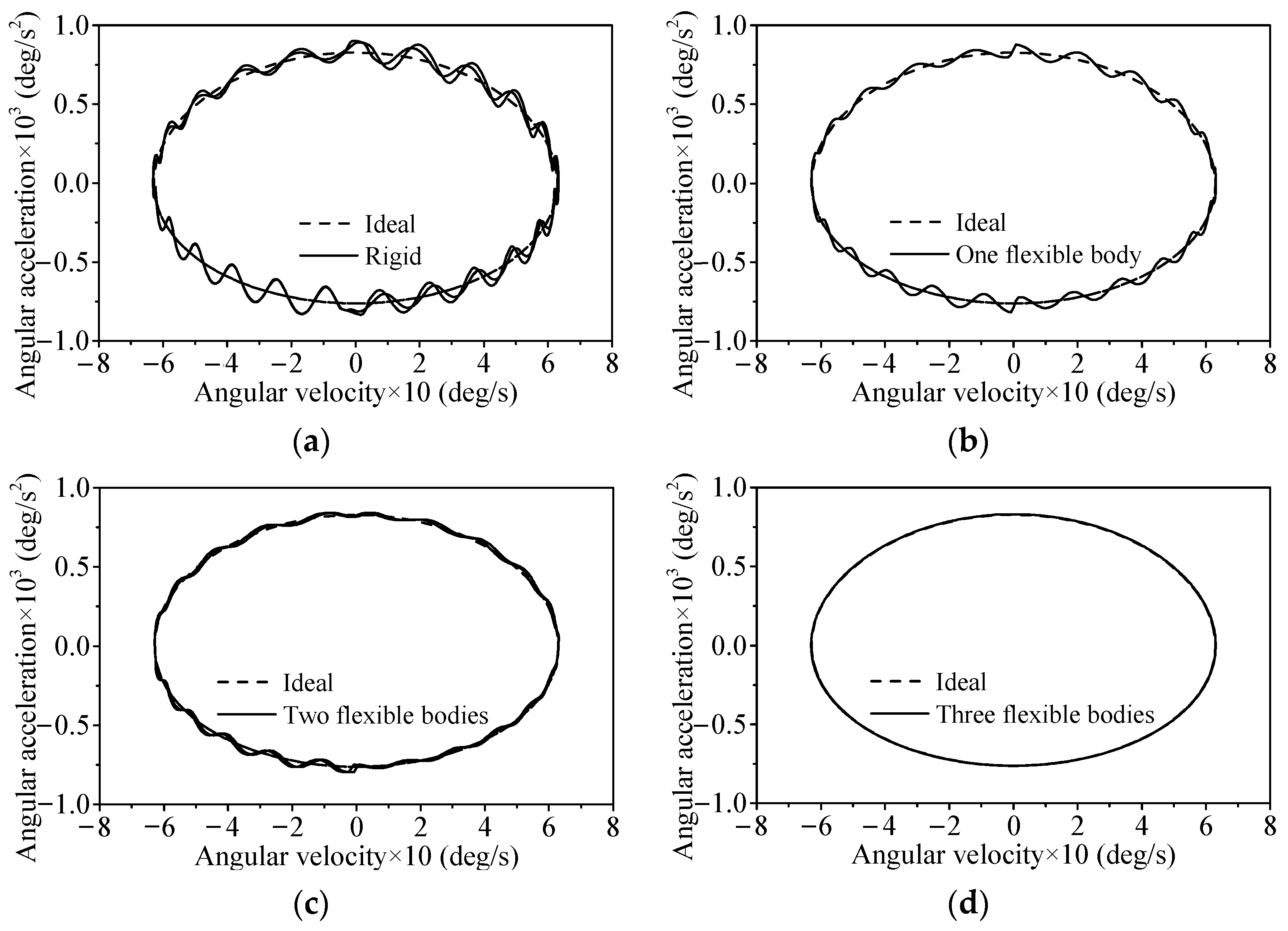
Figure 18.
Angular acceleration-angular velocity phase diagram of the rigid-flexible flap actuation system with different flexible body number when considering the single clearance joint: (a) rigid; (b) one flexible body; (c) two flexible bodies; and (d) three flexible bodies.
Figure 18.
Angular acceleration-angular velocity phase diagram of the rigid-flexible flap actuation system with different flexible body number when considering the single clearance joint: (a) rigid; (b) one flexible body; (c) two flexible bodies; and (d) three flexible bodies.
Figure 19.
Effects of clearance at joint 1 when considering the flexibility of the auxiliary rod: (a) angular velocity; (b) angular acceleration.
Figure 19.
Effects of clearance at joint 1 when considering the flexibility of the auxiliary rod: (a) angular velocity; (b) angular acceleration.
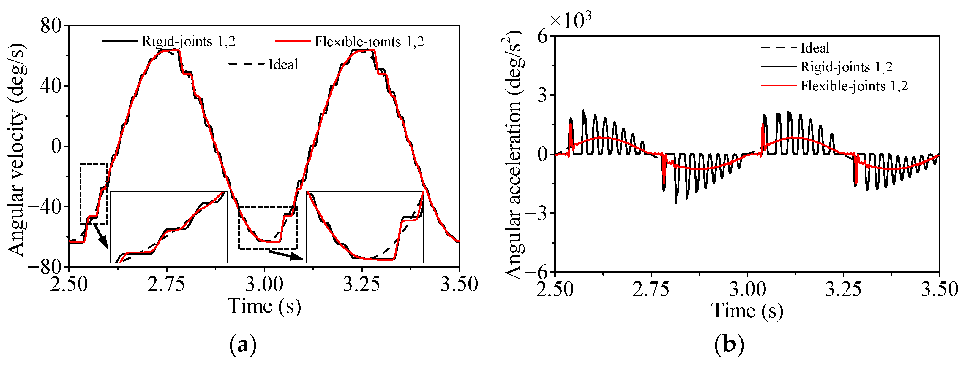
Figure 20.
Effects of clearances at joints 1 and 2 when considering the flexibility of the auxiliary rod: (a) angular velocity; (b) angular acceleration.
Figure 20.
Effects of clearances at joints 1 and 2 when considering the flexibility of the auxiliary rod: (a) angular velocity; (b) angular acceleration.
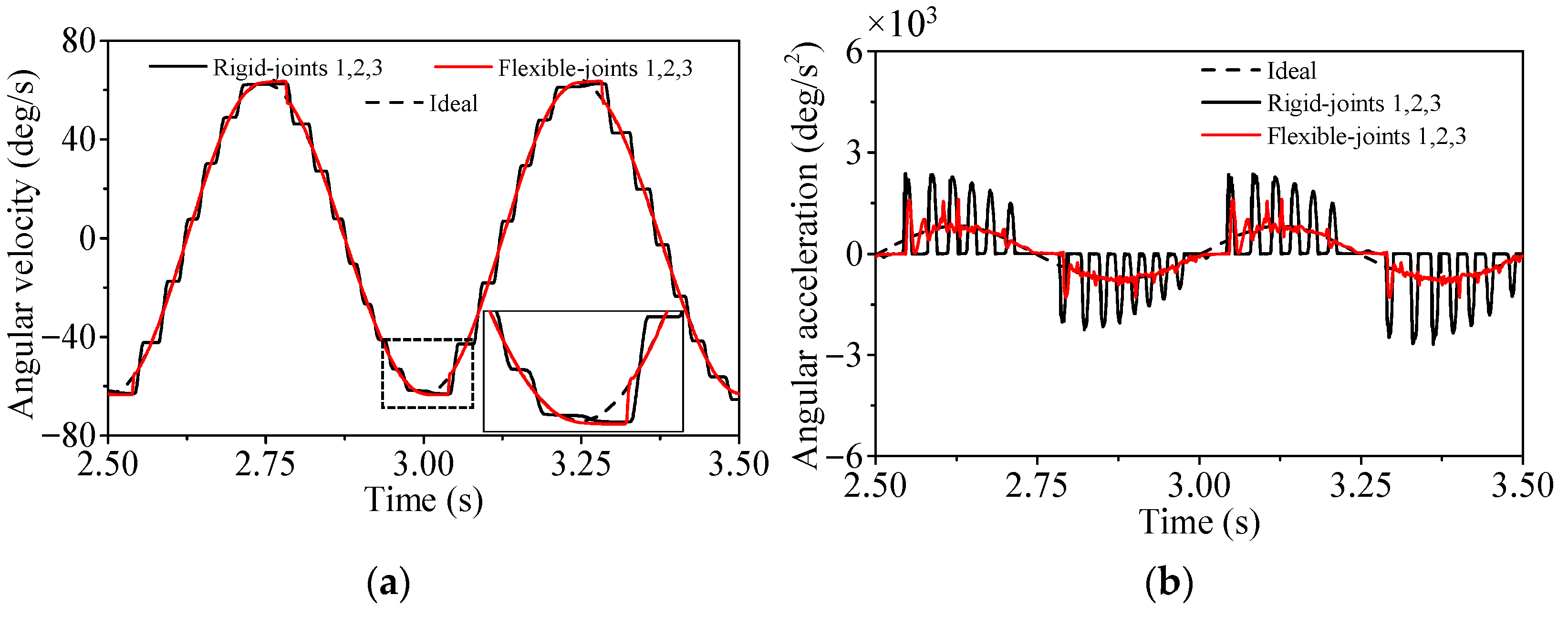
Figure 21.
Effects of clearances at joints 1, 2, and 3 when considering the flexibility of the auxiliary rod: (a) angular velocity; (b) angular acceleration.
Figure 21.
Effects of clearances at joints 1, 2, and 3 when considering the flexibility of the auxiliary rod: (a) angular velocity; (b) angular acceleration.
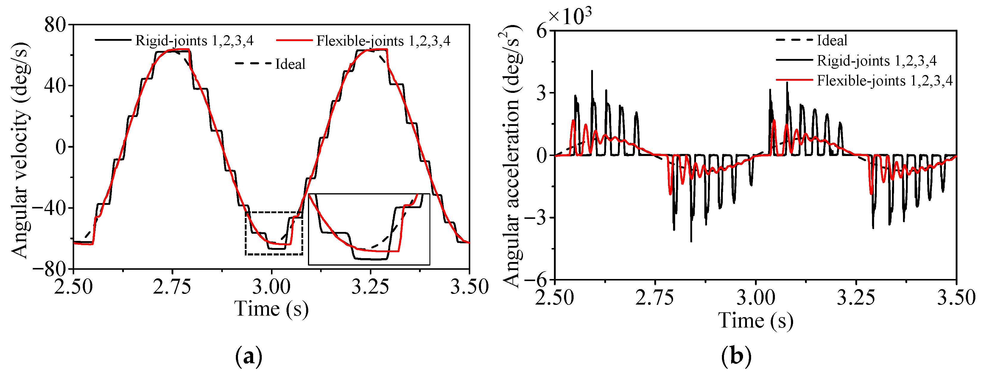
Figure 22.
Effects of clearances at joints 1, 2, 3, and 4 when considering the flexibility of the auxiliary rod: (a) angular velocity; (b) angular acceleration.
Figure 22.
Effects of clearances at joints 1, 2, 3, and 4 when considering the flexibility of the auxiliary rod: (a) angular velocity; (b) angular acceleration.
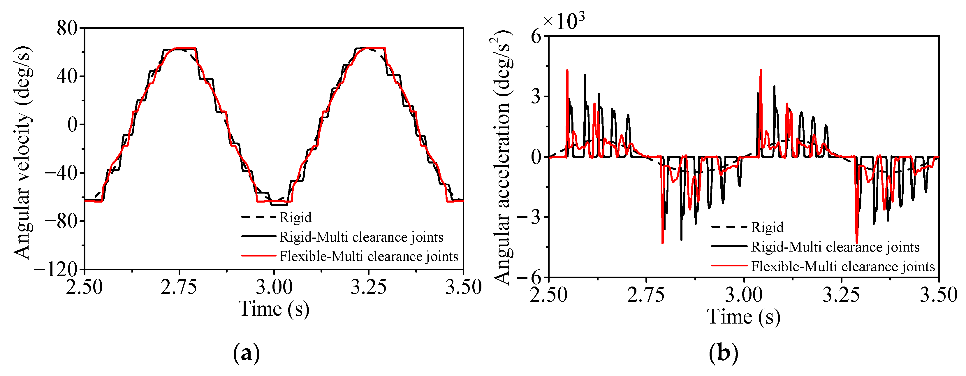
Figure 23.
Coupling effects of four clearance joints and three flexible bodies: (a) angular velocity; (b) angular acceleration.
Figure 23.
Coupling effects of four clearance joints and three flexible bodies: (a) angular velocity; (b) angular acceleration.
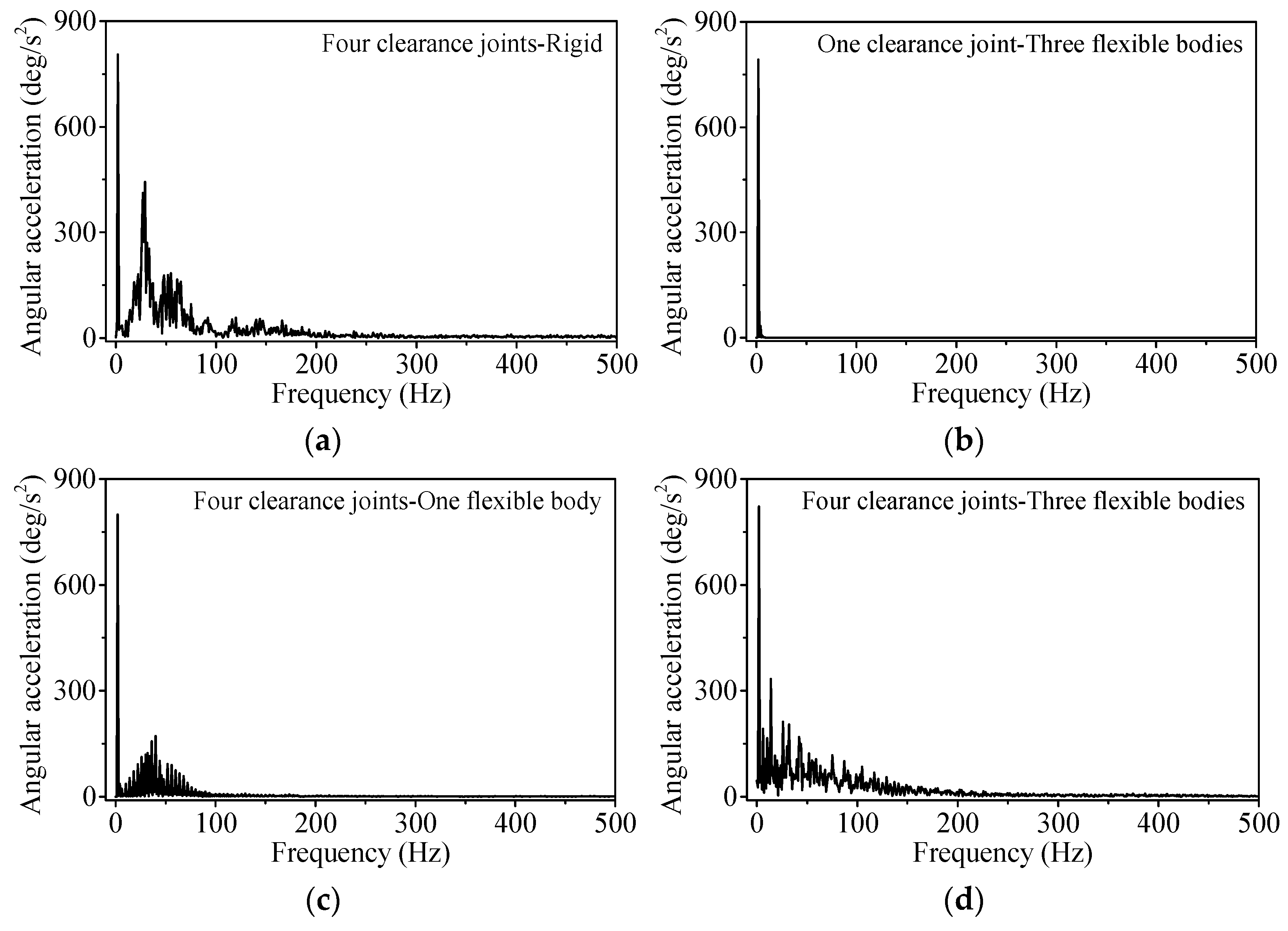
Figure 24.
FFT analysis of the angular acceleration of shaft with different cases: (a) four clearance joints-rigid; (b) one clearance joint-three flexible bodies; (c) four clearance joints-one flexible body; (d) four clearance joints-three flexible bodies.
Figure 24.
FFT analysis of the angular acceleration of shaft with different cases: (a) four clearance joints-rigid; (b) one clearance joint-three flexible bodies; (c) four clearance joints-one flexible body; (d) four clearance joints-three flexible bodies.
Table 1.
Parameters of the bearing and the journal.
Table 1.
Parameters of the bearing and the journal.
| Model | Radius (mm) | Young’s Modulus (GPa) | Poisson’s Ratio | Mass (kg) | Length (mm) | Initial Velocity (m/s) |
|---|
| Bearing | 10 | 207 | 0.3 | / | 15 | 0 |
| Journal | 9.9 | 207 | 0.3 | 1 | / | 0.5 |
Table 2.
Relative errors of the restitution coefficient.
Table 2.
Relative errors of the restitution coefficient.
| | Hertz [24] | L-N [26] | Gonthier [21] | Bai [28] | Wang [22] | Modified Model [23] |
|---|
| Actual restitution coefficient | 1 | 0.726 | 0.488 | 0.482 | 0.482 | 0.488 |
| Relative errors | 100% | 45.2% | 2.4% | 3.6% | 3.6% | 2.4% |
Table 3.
Mechanism parameters [
29].
Table 3.
Mechanism parameters [
29].
| | Length (m) | Mass (kg) | Moment of Inertial (kg·m2) |
|---|
| Crank | 0.05 | 0.343 | 0.000216 |
| Connecting rod | 0.3 | 1.072 | 0.034 |
| Slider | / | 0.347 | 0.000115 |
Table 4.
Relative errors of the oscillation peaks of the slider acceleration between simulation and experiment results.
Table 4.
Relative errors of the oscillation peaks of the slider acceleration between simulation and experiment results.
| | Oscillation Peak (m/s2) | Simulation | Experiment | Relative Error |
|---|
| Clearance Size (mm) | |
|---|
| 0.1 | 283.1 | 268.0 | 5.6% |
| 0.3 | 318.2 | 297.7 | 6.9% |
| 0.5 | 371.8 | 345.4 | 7.6% |
Table 5.
Simulation parameters.
Table 5.
Simulation parameters.
| Parameter | Description | Value | Unit |
|---|
| x | Actuator’s output displacement | 10 | mm |
| f | Actuator’s output frequency | 2 | Hz |
| L | Bearing’s length | 15 | mm |
| cf | Friction coefficient | 0.01 | / |
| cr | Restitution coefficient | 0.46 | / |
| v0 | Given tolerance for the tangential velocity | 0.1 | mm/s |
| v1 | Given tolerance for the tangential velocity | 1 | mm/s |
Table 6.
The eigenfrequencies of three flexible parts (Unit: Hz).
Table 6.
The eigenfrequencies of three flexible parts (Unit: Hz).
| | Eigenfrequencies | First | Second | Third | Fourth | Fifth |
|---|
| Parts | |
|---|
| Auxiliary lever arm | 3715.8 | 5437.1 | 7921.3 | 7946.1 | 7971.7 |
| Auxiliary rod | 690.40 | 1648.66 | 1869.88 | 2143.10 | 3588.54 |
| Lever arm | 5839.3 | 6201.3 | 7240.9 | 7976.3 | 9260.8 |


