1. Introduction
The gear system is one of the most widely used transmission systems due to its accurate transmission ratio and high efficiency. However, it inevitably vibrates under complicated working conditions. In particular, torsional vibrations may significantly degrade transmission performance and shorten the gear lifespan. As a result, it is necessary to explore effective methods for reducing the torsional vibrations of the gear system.
Recently, various passive methods have been studied for vibration control of the gear system. Bonori and Barbieri et al. [
1] developed an ad hoc genetic algorithm to optimize important parameters of micro-geometric modifications of spur gear pairs toward vibration and noise reduction. Bahk and Parker [
2] obtained a closed-form approximation of the vibration response with tooth profile modifications and investigated the effects of tooth profile modification on spur planetary gear vibrations. Qiu et al. [
3] proposed a fitness-predicted genetic algorithm to obtain optimal modifications of the gear system for vibration reduction. Xu et al. [
4] investigated a lightweight and low-vibration-amplitude web-design method to reduce the gear weight and vibrations. In addition to these structure optimization methods, various damping enhancement techniques have been explored. Ramadani et al. [
5] replaced the solid gear body with a lattice structure and filled it with polymer to increase system damping. Xiao et al. [
6,
7] adopted particle damping technology, i.e., placing particles in the gear structure to reduce the vibration amplitude through particle collision and friction energy dissipation. Yu et al. [
8] designed and produced a new foamed aluminum damping-plug and conducted experimental research on its vibration and noise reduction performance. Geng [
9] suggested a type of rigid–flexible gear with metal rubber to reduce gear vibration and improve system stability. Obviously, these methods require many modifications to existing structures.
In addition to passive control methods, various active control methods have been researched. Li et al. [
10] proposed a web active control method for vibration reduction of face gear transmission via active compensation of static transmission error. Wang et al. [
11] used the linear control method, the nonlinear control method, the periodic signal method, the constant load method, as well as the phase method to control the gear system out of the chaotic state. Wang et al. [
12] designed an active vibration control structure with built-in piezoelectric actuators (PZT) and proposed an adaptive fuzzy proportion integration differentiation (AFPID) control algorithm to reduce the vibration of the gear system. Liu et al. [
13] developed an active compensation controller to reduce the parametrically excited vibration of the gear pair and verified its effectiveness. Spiegelhauer et al. [
14] utilized an active vibration control strategy based on the full state feedback (LQG) to control unwanted vibration of gear transmission. Although active control methods have made remarkable progress, most of them face challenges when dealing with strong vibrations. Due to the limited power output of active actuators such as PZT, there are potential risks of overload damage [
15]. More importantly, the system stability of active control methods is a crucial issue. If designed unreasonably, active control forces probably excite vibration rather than decrease vibration [
16].
Internal resonance is a special modal interaction phenomenon of the nonlinear multi-degree-of-freedom system. When internal resonance is established between the two vibration modes, a vibration energy transfer channel is built accordingly, and then the vibration energy of one mode can be transferred to the other mode. Usually, it is viewed as harmful and is expected to be avoided [
17,
18]. However, Golnaraghi [
19] first utilized internal resonance to reduce the vibration of a cantilever beam. Then, Oueini [
20] designed an analog controller to implement internal resonance and control a cantilever beam’s vibration. Harouni [
21] proposed an internal resonance vibration absorber that works with a negative stiffness mechanism and studied its effect on vibration reduction. In these studies, the primary system was a rigid body supported by springs. On the other hand, the distributed flexible body model was researched. Yaman [
22] reduced the vibration of a flexible cantilever beam using a pendulum attached to the tip mass. Hui [
23] decreased the translational vibration by transferring the internally resonant energy from the symmetrical mode to the anti-symmetrical mode. Furthermore, Bian and Gao [
24] designed an internal resonance vibration absorber with adjustable parameters and proposed a semi-active vibration absorption method for the flexible manipulator undergoing rigid motion. Although these research works are promising, few studies have focused on reducing the torsional vibrations of the gear system via internal resonance. Since the dynamic model of the gear system is completely different from that of a flexible mechanism, whether internal resonance can be established and utilized to reduce the torsional vibration of the gear system has not been researched.
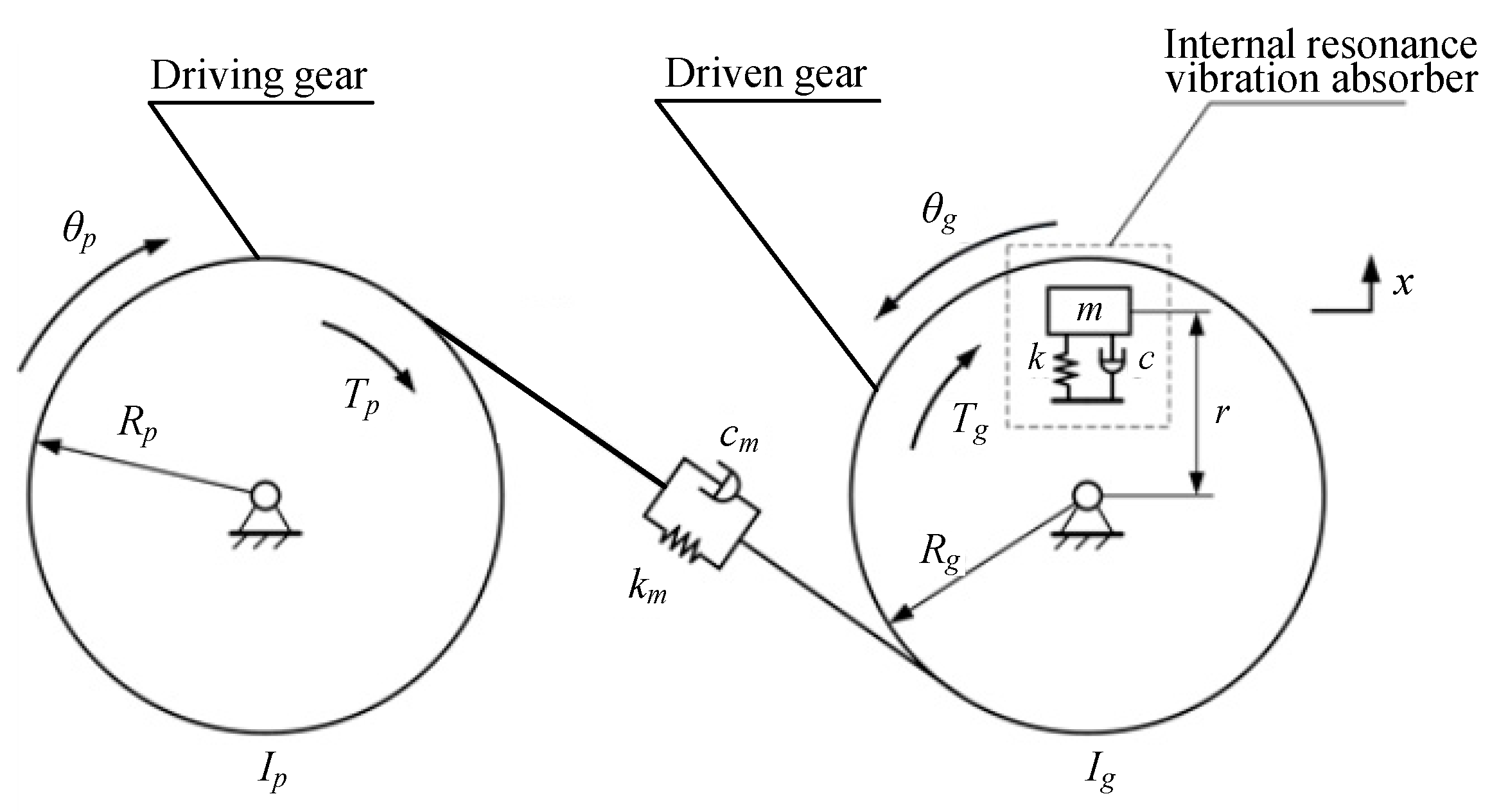
In view of this, an internal resonance-based method is proposed in this paper to reduce the torsional vibrations of the gear system as an exploration to combine internal resonance with gear vibration control. Firstly, the dynamic model of the gear system and the internal resonance vibration absorber are established. Secondly, according to the coupling relationship between the gear torsional vibration mode and the vibration absorber mode, the 1:1 internal resonance condition is analyzed by the multiple scale method, and sufficient and necessary conditions for establishing internal resonance are obtained. Through stability analysis, the vibration energy transfer channel based on internal resonance is successfully established. Finally, vibration reduction performances are examined based on numerical and virtual prototyping simulations, thereby verifying the effectiveness of the proposed method. The proposed method exhibits potential advantages in reducing vibration responses induced by unpredictable excitations in complex environments, e.g., wind power gear systems.
3. Establishment of the Internal Resonance Energy Transfer Channel
In this section, a vibration energy transfer channel based on 1:1 internal resonance is successfully established to reduce the gear torsion vibrations with the help of the vibration absorber.
3.1. Perturbation Analysis
It is essential to make the dynamic equations dimensionless, and the following transformations are used, i.e.,
Thus, the gear torsion vibration mode, Equation (12), and the vibration absorber mode, Equation (13), are nondimensionalized as
where
and
represent the first and second derivatives with respect to
;
represents the ratio of the natural frequency of the vibration absorber mode to the natural frequency of the gear torsional vibration mode;
.
Equations (16) and (17) are solved by the multiple scales method. A small perturbation parameter
is introduced through the following transformations:
Substituting Equation (18) into Equations (16) and (17), one obtains:
The first-order approximate solutions to Equations (19) and (20) take the form
where
denotes a fast time scale characterized by the inherent movement of the system, and
denotes a slow time scale characterized by the modal vibration. The time derivatives with respect to
can be rewritten in terms of the new time scales as
where
.
Substituting Equations (21)–(24) into Equations (19) and (20), then equating coefficients of the same order of , one obtains the following differential equations:
The general solutions of Equations (25) and (26) can be expressed in the form:
where
and
are the functions of the slow time
, determined by the solvability conditions in the next section;
denotes the complex conjugate of the preceding terms.
Substituting Equations (29) and (30) into Equations (27) and (28), one obtains:
where
denotes the complex conjugate terms.
3.2. Internal Resonance Analysis
The coupling terms of the gear torsional vibration mode and the vibration absorber mode on the right-hand side of the Equations (16) and (17) are underlined. When the frequency of these coupling terms is the same as the frequency of the modal coordinate and , the resonance phenomenon will be excited, potentially establishing an internal resonance energy channel.
The first-order approximate solutions Equations (21) and (22) are substituted into the underlined coupling terms, and only the order
is considered. It is found that the underlined items
and
in Equation (16) have a common excitation frequency
. Let
be equal to the dimensionless angular frequency of the gear torsional vibration, then one obtains
Similarly, for the underlined item in Equation (17), when its frequency is equal to the frequency of the vibration absorber, Equation (33) can also be obtained. It can be inferred that the gear torsional vibration mode and the vibration absorber mode are strongly coupled, and internal resonance may occur. Therefore, the 1:1 internal resonance condition is analyzed in this paper.
The detuning parameter
is introduced, which reflects the amount of deviation between modal frequencies
and
, i.e.,
Then,
and
can be expressed as:
Equations (35) and (36) are substituted into Equations (31) and (32), and the secular and small divisor terms are eliminated. Then one obtains:
In order to solve Equations (37) and (38),
and
are expressed in polar form for convenience, i.e.,
where
,
,
,
are unknown real functions of the slow time
;
and
represents the modal amplitudes.
Inserting Equations (39) and (40) into Equations (37) and (38), then setting the real and imaginary parts to 0, one obtains:
where
and
can be eliminated from Equations (43)–(45), i.e.,
In order to investigate the energy transfer between the driven gear and the vibration absorber, the undamped condition is analyzed. Divide Equation (41) by Equation (42) to obtain
Let
then one can obtain
where
is a constant of integration, which reflects the initial energy of the system.
Since in Equation (49), and are bounded and negatively correlated, indicating that the vibration energy of the gear torsional vibration mode and the absorber vibration mode is continuously exchanged. This phenomenon proves that the energy transmission channel based on internal resonance has been successfully established.
3.3. Verification of Internal Resonance
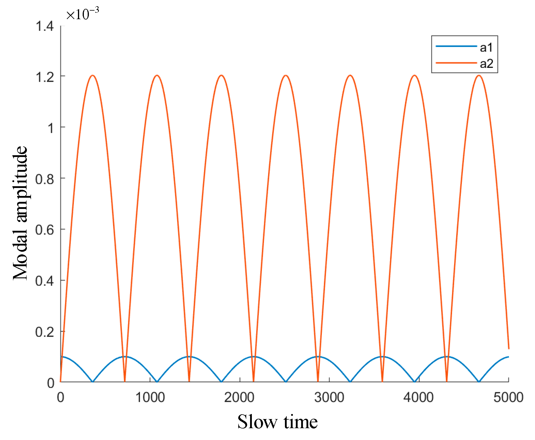
In this section, the modal amplitude change, which reflects the evolution of vibration energy, is obtained through numerical simulation in order to verify the successful establishment of the internal resonance, thereby proving the correctness of the theoretical analysis.
Let
,
,
,
, and thus the amplitude diagram of the gear torsional vibration mode and the vibration absorber mode is obtained, as shown in
Figure 3. In the absence of damping, the system’s energy is continuously exchanged between the two modes without attenuation. Furthermore, the two modes have anti-phase amplitude modulation motion, proving that the internal resonance has been established successfully.
4. Vibration Reduction Characteristics of the Internal Resonance Vibration Absorber
In order to build an efficient energy transfer channel and improve vibration reduction performance, it is necessary to study the vibration reduction characteristics of the internal resonance vibration absorber. For this reason, this section investigates the validity of the vibration absorber, analyzes the influence of damping on vibration absorption performance, and studies the robustness of the vibration absorber.
4.1. Validity Investigation
The validity of the internal resonance vibration absorber for vibration reduction can be verified by comparing the numerical simulation of the gear system with and without the vibration absorber.
Let the external load
, and the time-varying meshing stiffness has the average value to observe the internal resonance phenomenon, i.e.,
. According to Equation (12), the modal frequency of gear torsional vibration can be obtained, i.e.,
From Equation (13), one obtains the stiffness of the internal resonance vibration absorber in this study, which is
When the vibration absorber damping
, the displacements of the gear torsional vibration mode and the vibration absorber mode are shown in
Figure 4. The gear torsional modal displacement represents the gears’ displacement along the meshing line, and the vibration absorber modal displacement represents the absorber’s displacement along the radial direction of the driven gear. It can be found that the peaks and valleys of the two modes’ vibration displacement appear alternately, indicating that the vibration energy is transferred alternately between the gear system and the vibration absorber, thereby proving the successful establishment of the internal resonance energy channel.
Next, the time-varying mesh stiffness expression in Equation (4) is used to observe the damping effect of the internal resonance vibration absorber under actual conditions. Let the meshing damping
and the damping of the internal resonance absorber
. In order to obtain an intuitive vibration reduction effect of the vibration absorber, the torsional vibration displacement of the gear system with and without the vibration absorber is compared, as shown in
Figure 5.
The internal resonance vibration absorber reduces the torsional vibration displacement amplitude, i.e., the gears’ relative displacement amplitude along the meshing line, to 26.48 μm within 8 s, as shown in
Figure 5. Compared to the system without the vibration absorber (39.01 μm), the vibration absorber reduces the amplitude of the gear torsional vibration by 32.1%. During this process, the energy of the gear torsional vibration mode is transferred to the vibration absorber mode via the internal resonance energy transfer channel and is continuously dissipated by the damping of the vibration absorber.
As a result, the amplitude of gears’ torsional vibrations can be significantly reduced by the internal resonance vibration absorber, and thus the proposed gear vibration reduction method based on internal resonance is effective. The above simulation results exhibit the potential application value of this method in the field of gear transmission.
4.2. Influence of Vibration Absorber Damping
4.2.1. System Stability under Damping Conditions
Since instability is harmful to system motion, it is necessary to assess the stability of the internal resonance steady-state solution under damping conditions. The steady-state solution of the nonlinear dynamic equation is
. Substituting the steady-state solution into Equations (41), (42) and (46), one obtains:
The solution of Equation (52) can be defined as:
Therefore, one can ascertain the system’s stability by evaluating the Jacobian matrix. Let
; then, the Jacobian matrix is:
Since , , and are all positive, the eigenvalues of the Jacobian matrix are all negative. Therefore, the steady-state solution has asymptotic stability, and the motion of the gear system and the internal resonance vibration absorber are stable. This means that in the presence of damping, the gear torsional vibration energy can be stably transferred to the vibration absorber through the energy transfer channel and dissipated through the latter’s damping.
4.2.2. Influence of Damping on System Vibration Reduction
In
Section 3.3, the equations of gear torsional vibration mode and internal resonance vibration absorber mode in the slow time scale have been solved. The modal amplitude and phase angle satisfy the following equations:
The gear meshing damping is simplified as linear viscous damping, and thus the damping coefficient
. When
, the influence of differences in damping of the vibration absorber on the modal amplitude of the gear torsional vibration is shown in
Figure 6.
It can be seen from
Figure 6 that, as the damping ratio
increases from 0.001 to 0.007, the ability of the vibration absorber to reduce the modal amplitude of the gear torsional vibration is significantly enhanced. When the damping of the vibration absorber is small, the ability to absorb vibration energy is strong, but the ability to dissipate vibration energy is weak. At this time, an appropriate increase of
can enhance the vibration absorption capacity of the vibration absorber. However, when
is further increased, the effect of reducing vibration slows down because the large damping of the vibration absorber hinders the transmission of the gear’s vibration energy. Therefore, improperly selected damping is not conducive to vibration reduction. When
, i.e.,
, the ability of the vibration absorber to vibration absorption and energy consumption reaches the best and thus the vibration absorber achieves the best vibration reduction effect.
4.3. Robustness Study of the Vibration Absorber
Under complex working conditions, the designed vibration absorber must have a strong ability to resist external interference. In view of this, the robustness of the internal resonance vibration absorber is verified by studying the gear torsional vibration’s modal energy transfer rate in this section.
Let the effective working time interval be 0 to 2000 of the slow time and the value range of
be (−0.4, 0.35). As shown in
Figure 7, as the absolute value of
increases, the fluctuation of modal amplitude
keeps shrinking, which means that the energy transfer rate decreases. This phenomenon indicates that as the frequency ratio of the two modes deviates from the necessary and sufficient conditions for establishing internal resonance, the energy transfer between the modes decreases.
The maximum change in modal amplitude
is measured, as shown in
Table 3. From this, the change curve of the energy transfer capacity with respect to different values of
is obtained, as shown in
Figure 8. The change curve reaches its peak when
and is approximately symmetrical on both sides of the peak. Taking the curve’s half power point on both sides of the peak, the ordinate is
, and the corresponding detuning parameters are obtained as
and
, respectively. Thus, the adequate working bandwidth of the vibration absorber is
, within which the vibration absorber can efficiently absorb the torsional vibration energy. In this paper, the bandwidth of the vibration absorber (i.e., (−1.4, 1.4)) is large, which verifies that the system’s robustness is strong enough.
5. Verification of Vibration Reduction Effect via Virtual Prototype Simulation
The above studies are based on theoretical analysis and numerical simulation. Based on this, it is also necessary to use a recognized method to verify the effect of the internal resonance vibration absorber. Therefore, COMSOL Multiphysics® software was used to further verify the vibration reduction effect of the internal resonance vibration absorber under the action of initial excitation and periodic excitation in this section. Since it calculates dynamic responses of the gear system in different ways than in this paper, more trustable results can be obtained to verify the above work.
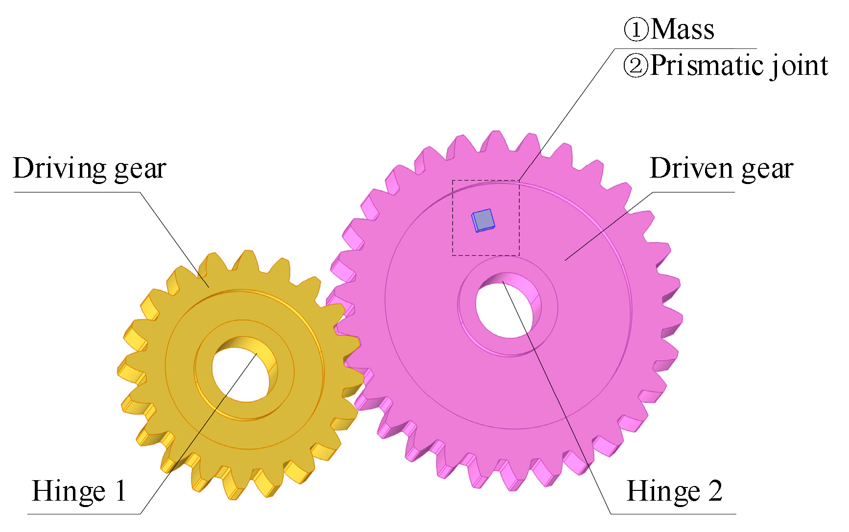
5.1. Establishment of Virtual Prototype Model
A virtual prototype model of the gear system and the internal resonance vibration absorber was established according to the parameters in
Table 1 and
Table 2, as shown in
Figure 9. The two gears are connected with the ground by hinges. The two gears are connected by a gear-pair, of which the time-varying meshing stiffness is set according to the previous calculation results. Moreover, the vibration absorber is represented by a mass connected to the driven gear through a prismatic joint, and the axis of the prismatic joint is along the gear’s radial direction.
5.2. Vibration Reduction Effect under Transient Excitation
In order to verify the vibration energy transfer and dissipation mechanism based on internal resonance, a gear system subjected to a transient excitation was investigated via virtual prototyping simulation. The angular velocity of the driving gear increases from 0 to 800 rad/s within 0.001 s and then remains constant. The torsional vibration of the gear system is excited by the sudden change of the rotational speed. Let the meshing stiffness
, the load torque on the driven gear
, and the stiffness of the vibration absorber
. Then, the vibration reduction characteristics of the vibration absorber under the transient excitation can be studied by changing the vibration absorber damping
. Let
be 0, 1, 9.5, and 100
; the vibration displacement of the gear and the vibration absorber are obtained, as shown in
Figure 10.
As shown in
Figure 10a, the internal resonance has been successfully established. The torsional vibration energy is transferred to the internal resonance vibration absorber, causing the vibration absorber’s mass unit to vibrate near the equilibrium position. When the amplitude of the torsional vibration reaches a minimum value, the amplitude of the vibration absorber reaches a maximum value, indicating that the vibration energy flows into the vibration absorber at this time, and vice versa. This phenomenon shows that the vibration energy is transferred between the two modes, proving that the internal resonance energy transfer channel works effectively in the gear system.
Furthermore, as shown in
Figure 10b–d, with the increase in the vibration absorber damping
, the vibration reduction capability shows a trend of first becoming stronger and then weaker. As shown in
Figure 10b, when
, the vibration absorber’s amplitude fluctuates greatly, indicating a strong ability to absorb torsional vibration energy. However, the vibration absorber has a weak ability to dissipate the vibration energy, and the torsional vibration amplitude is only reduced from 20.5 μm to 13.5 μm within 0.3 s. As shown in
Figure 10c, when the selected damping of the vibration absorber is suitable, i.e.,
, the torsional vibration amplitude can be effectively reduced to 4 μm. Moreover, as shown in
Figure 10d, when
, the vibration absorber modal amplitude has almost no fluctuation. Since excessive damping prevents the torsional vibration energy from flowing into the vibration absorber mode, the vibration reduction effect is not satisfactory. These virtual prototyping simulation results further verify the accuracy of the presented theoretical analysis.
5.3. Vibration Reduction Effect under Periodic Excitation
For the torsional vibration caused by various periodic excitations, such as time-varying meshing stiffness, the internal resonance vibration absorber can effectively suppress the vibrations.
Let the angular velocity of the driving gear be 800 rad/s, the load torque on the driven gear
, the stiffness of the vibration absorber
N/mm, and the vibration absorber damping
c = 9.5 N/(m/s). The meshing stiffness is set according to Equation (5) and the meshing damping
. The diagram of gear torsional vibration displacement with and without the vibration absorber is obtained via virtual prototyping simulation, as shown in
Figure 11.
The initial torsional vibration amplitude of the gear system is 37 μm. Without the vibration absorber, the torsional vibration amplitude of the gear is reduced to 32 μm within 2 s. Meanwhile, the torsional vibration amplitude for the gear system with an internal resonance vibration absorber is reduced to 27.5 μm within 2 s, 14.1% less than that without the vibration absorber. Within 6 s, the torsional vibration amplitude without the vibration absorber is reduced to 30.5 μm, while the torsional vibration amplitude with the vibration absorber is reduced to 22 μm, i.e., 27.9% less than that without the vibration absorber. Therefore, the internal resonance-based method can effectively decrease the torsional vibration of the gear system.
In practice, there are various uncertainties in the gear system, such as assembly errors, machining errors, wear, and other factors that influence gear transmission performance. Usually, these factors can be converted to the gear transmission error, which is generally represented by a harmonic function [
26], i.e.,
where
and
are the fixed value and amplitude of the transmission error, respectively;
is the meshing frequency of the gear pair; and
is the initial phase angle, generally taking the value of 0.
In order to consider various uncertainties in the gear system and provide more realistic results, the gear transmission error is taken into account in the virtual prototyping simulations. Let the amplitude of the transmission error
[
26], with other parameters remain unchanged. The vibration reduction effect of the internal resonance vibration absorber is shown in
Figure 12.
It can be found that the amplitude of the gear’s torsional vibration increases significantly after considering the transmission error. The initial torsional vibration amplitude of the gear system is 68.5 μm. The torsional vibration amplitude of the gear system with an internal resonance vibration absorber is reduced to 48 μm within 2 s, 19.4% less than that without the vibration absorber (59.5 μm). Within 4 s, the torsional vibration amplitude without the vibration absorber is reduced to 52 μm, while the torsional vibration amplitude with the vibration absorber is reduced to 39 μm, i.e., 25% less than that without the vibration absorber. Therefore, the torsional vibration energy can be transferred to and dissipated by the vibration absorber even after considering more complex factors.
In conclusion, even though several uncertainties in the gear system are taken into account, the internal resonance-based method can still effectively decrease the torsional vibration of the gear system.
6. Conclusions
Torsional vibration can severely degrade transmission performance and shorten the gear lifespan. Until now, most passive vibration reduction methods rely on structure optimization and new damping materials to reduce the torsional vibration of the gear system. Obviously, these methods require many modifications to existing structures. On the other hand, several active vibration reduction methods have been suggested in recent years. When dealing with strong vibration, however, most of them face challenges. Due to the limited power output of active actuators such as PZT, there are potential risks of overload damage. More importantly, the system stability of active control methods is a crucial issue. If designed unreasonably, active control forces probably excite vibration rather than suppress vibration.
In view of this, an internal resonance-based method is proposed to reduce the torsional vibrations of the gear system. A vibration absorber is attached to the gear system for establishing a nonlinear interaction channel to dissipate the vibration energy of the gear torsional vibration mode. Based on the dynamic model of the gear system and the internal resonance vibration absorber, the 1:1 internal resonance condition is analyzed, and sufficient and necessary conditions for establishing internal resonance are obtained. Through stability analysis, the vibration energy transfer channel, based on internal resonance, is successfully established, by which the vibration energy can be transferred to and dissipated by the vibration absorber. Based on numerical and virtual prototyping simulations, vibration reduction performances are examined, including effectiveness, damping characteristics, and robustness. The research results show that the proposed internal resonance-based method can effectively reduce the torsional vibrations of the gear system.
Essentially, the proposed internal resonance-based method is a passive vibration absorption method. Different from conventional vibration absorption methods characterized by linear neutralization, this method absorbs vibration energy via nonlinear modal interaction provided by internal resonance. As a result, a translational mode can absorb the vibration energy of a torsional mode. On the other hand, compared with those passive methods, which rely on structure optimization and new damping materials, this method does not require many modifications to existing structures. As long as the vibration absorber is installed on the gear system, it can effectively absorb the torsional vibration of the gear system. Furthermore, this method aims to dissipate vibration energy rather than actively suppress vibration with the help of external energy input. Therefore, it is more suitable for mitigating strong vibration than those active control methods, which rely on numerous actuators with limited energy output.


