Review

The Key Role of 3D Printing Technologies in the Further Development of Electrical Machines

1
Electrical Machines and Drives Department, Technical University of Cluj-Napoca, RO-400114 Cluj-Napoca, Romania
2
Vehicle Industry Research Center, Széchenyi István University, H-9026 Győr, Hungary
*
Author to whom correspondence should be addressed.
Machines 2022, 10(5), 330; https://doi.org/10.3390/machines10050330
Submission received: 3 April 2022 / Revised: 24 April 2022 / Accepted: 26 April 2022 / Published: 1 May 2022
(This article belongs to the Topic Advanced Electrical Machines and Drives Technologies)

Abstract

:
There is a strong general demand for the permanent improvement of electrical machines. Nowadays, these are at their near maximum potential, and even small further improvements can only be achieved with great effort and high cost. The single solution should be a paradigm shift in their development, by using radically new approaches to topology, materials, and fabrication. Therefore, the application of diverse 3D printing techniques for advanced fabrication in this field is inevitable. Therefore, these new approaches are receiving a great deal of attention among electrical machines designers. In the paper, the possible applications of these new fabrication technologies in the field of electrical machines are surveyed. The focus is set on emphasizing the advancement over the traditional manufacturing approaches.

1. Introduction

Electrical machines (EM) are an essential part of both advanced industry and the electrification of transportation. The global electrical machine market is expected to increase to 195.1 billion USD by 2030, growing at a compound annual growth rate (CAGR) of 6.3% during this period [1].
The applications of EMs come up against several frequently contradictory requirements, e.g., great power/torque density, high efficiency, wide speed range, good dynamics, high degree of reliability and robustness, low level of acoustic noise, and, of course, reduced cost [2]. However, EMs seem to have almost reached their maximum potential. Even small further improvements can only be made by investing an enormous amount of effort at a significant expense. It is sufficient to mention the hard work carried out by designers to ensure induction machines (IMs) comply with drastic energy efficiency regulations [3]. It can be assumed that advancing to the next technological level in this field can only be achieved by a paradigm shift, namely by employing entirely new approaches with regard to topologies, the materials used, and manufacturing [4]. These novel and innovative advances are interdependent, and only when applied together will they bring the needed breakthrough.
The classical manufacturing technologies available strongly limit how industrially widespread both the new conductive and magnetic materials are, as well as innovative EM constructions. Therefore, the possible application of novel, revolutionary fabrication technologies, such as additive manufacturing (AM), must be very seriously considered, even more so since this is a constituent component of so-called “smart factories”, which maximize benefits brought about by the Fourth Industrial Revolution (named Industry 4.0). This technology is considerably different from traditional manufacturing processes such as subtractive (drilling, milling), formative (casting), and joining processes (welding, fastening) [5].
This paper focuses on the possible improvements brought about by the implementation of AM with regard to the fabrication of iron cores, permanent magnets (PMs), windings, and cooling systems for EMs and usable materials. Furthermore, some typical applications of using 3D printing in this field are surveyed.

2. Additive Manufacturing Technologies

AM, also referred to as 3D printing, involves the layer-by-layer processing of parts. It is an advanced technology that combines digitally controlled high-precision mechanical processing equipment, and the use of advanced materials fitted to this kind of processing. Huge research, development, and investment efforts over the past few years have made this technology essential in almost all industries.
By applying AM methods, components of essentially any complex shape of a great variety of materials can be precisely produced without scratches. The obtained parts can have lower volume and mass than if they were traditionally manufactured. Outputs from advanced topology optimization (including artificial intelligence-based ones) can be closely achieved. Most of the AM technologies enable the easy integration (simultaneously processing) of components even made of different materials, which previously had to be separately fabricated. A notable advantage of this method is that the processing costs do not depend on the component complexity. By using AM, the fabrication of all the basic components of an EM (magnetic core, PMs, conductors/windings, cooling system, and housing) is possible [6].
The many AM technologies have been classified into seven categories by the American Society for Testing and Materials (ASTM) [7,8]. A large proportion of them is useful for the fabrication of EMs. Next, only these are mentioned.
Powder bed fusion (PBF) is one of the most widely used AM methods [9]. Its most common variants are selective laser melting (SLM), also called laser beam melting (LBM) [10,11], and selective laser sintering (SLS) [12]. It consists of the successive melting of thin layers of metal powders by a laser beam. Even parts compounded by two different materials can be together fabricated [13]. Direct metal laser sintering (DMLS) is another similar technique, developed especially for the 3D printing of alloys composed of materials with different melting points that are fused on a molecular level at high temperatures [14].
Directed energy deposition (DED) is also a popular 3D printing process, which uses lasers, electron beams, or electric arcs to melt and deposit metal powders or wires in successive layers [9,15]. Within this technology, the laser-engineered net shaping (LENS) method seems the most suitable for manufacturing the iron cores of EMs from a diverse range of metal powders. As this device can inject the metal powder anywhere in the heated workspace, the metal layer can be deposited on any complicated curved surfaces.
Fused deposition modeling (FDM), also known as fused filament fabrication (FFF), involves placing a thin continuous melted filament composed of a thermoplastic material layer-by-layer to form the desired component [16]. This is adequate for the fabrication of bonded PMs.
The binder jetting (BJ) AM technology consists of a printhead selectively depositing drops of binding liquid onto a thin layer of powder, thereby forming a layer of the structure to be fabricated [17]. Cold spraying (CS) is based upon the amalgamation of microparticles accelerated faster than the speed of sound and sufficiently directed onto an appropriate substrate. It is a cheap technology that uses inexpensive powders, but the precision of the final products is low [18]. By utilizing CS manufacturing, iron cores, windings, and PMs can be produced. Laminated Object Manufacturing (LOM) is also a sheet lamination 3D printing technique that is widely applied. It uses temperature and pressure to fuse or laminate layered materials [9]. For a great variety of materials, stereolithography (SLA) technology can also be used [19,20]. Upon this, a liquid photosensitive prime material is turned into a 3D solid object layer-by-layer by using a low-power laser beam and photopolymerization.
Despite rapid advances in various AM technologies, in some high-tech applications, standalone metal-powder-based 3D printing cannot achieve the very tight geometric tolerances and surface integrity required. In such cases, the so-called hybrid AM techniques must be applied, where the 3D printed parts are further post-processed to precisely meet all the design constraints. There are already hybrid AM systems that are commercially available that combine laser-based 3D printing with advanced post-processing techniques (such as machining, heat treatment, surface treatment, etc.) that can also produce complex parts of the EMs [21].

3. Materials for 3D Printing of Electrical Machines

3.1. Soft Magnetic Materials

High permeability and saturation, besides low iron core losses, are the basic technical requirements for materials the magnetic core of EMs are manufactured of. Traditionally, they are made of punched non-oriented electric steel laminations stacked together [22]. Even if the soft magnetic materials used are continuously enhanced (see, for example, the improvements of iron-silicon alloys in [23]), significant progress could be made concerning the iron losses by simply reducing the thickness of the laminations. However, due to the low mechanical strength of the thin sheet, the laminations are bent during stamping and cannot be packed at a high stacking coefficient. Electrical steel lamination technology also limits the flexibility in EM design since complex-shaped 3D iron cores make it difficult to assemble laminations [22].
AM can bring advancements in this field by enabling the 3D printing of excellent-quality powdered soft and hard magnetic materials. By using this, complex-shaped iron cores that allow true 3D magnetic flux paths can be made, and good control over electromagnetic and mechanical properties of the cores can be achieved [24].
A great variety of soft magnetic materials to be used in AM of EMs is at the disposal of design engineers. Most of the traditional soft magnetic alloys, such as Fe-Si, Fe-Ni, Fe-Co, and soft magnetic composites (SMCs) can be 3D printed [25]. Besides these, there is intensive research to improve the quality of other magnetic materials (such as amorphous and nanocrystalline ones) to shape their properties to the requirement laid down for EM iron cores [26].
Nowadays, iron alloyed with a low quantity of silicon is the most-used material in the construction of iron cores (in both grain-oriented and non-oriented states). Usually, up to 1% aluminum and less than 0.5% manganese are also added to the alloy to improve its performance. Finding the ideal recipe is complicated since in all cases the change in the amount of a material has a contradictory effect on the overall performance of the alloy [23].
Recent studies have demonstrated that iron-silicon alloys with a high 6.5% silicon composition (called Fe-6.5Si) are most adequate for the AM of the iron cores of EMs [27]. Parts made of Fe-6.5Si employing DMLS technology have better magnetization properties than Fe-Si alloys with a lower silicon content (Fe-3Si having only 3% Si), and the eddy current losses at 50 Hz are reduced by more than 50% [28].
Moreover, Fe-Ni alloys with up to 80% nickel composition (the Permalloy or the Supermalloy) can be candidates for 3D printing the iron cores of EMs. These have excellent magnetic properties concerning their losses and magnetic permeability, but relatively low saturation magnetic flux density. These alloys can be easily 3D printed due to their exceptional mechanical permeability. For fabricating EMs’ iron cores, Fe-Ni alloys can be processed by diverse AM technologies, such as DED [29], SLM [30], and FDM [31].
Fe-Co alloys have the greatest saturation magnetic flux density among the soft magnetic materials considered here, with 2.45 T for the 50-50% Fe-Co alloy, trade named Permendur [32]. Supplementarily, this alloy has low coercivity and losses and high magnetic permeability and Curie temperature.
Adding nickel, Perminvar (30Fe-25Co-45Ni) can be obtained, which has constant magnetic permeability across a wide field range. By enhancing it with 2% vanadium (Hiperco—49Fe-49Co-2V), its ductility (machinability) and electrical resistivity are radically improved, without significantly losing its other good magnetic properties [33,34].
All the Fe-Co alloys are suitable for AM by both SLM [32] and LENS [34] methods.
In the past, SMCs were the single potential alternatives to electrical steel laminations in the EMs iron core construction, especially when complex 3D-shaped iron cores had to be manufactured [35]. These are iron powder particles bounded by an insulating coating. Their magnetic characteristics (saturation flux density, magnetic permeability, and iron core losses) compared with electric steel laminations at low frequencies are slightly worse. This is mainly due to the non-magnetic space between the iron powder particles. However, due to its great electrical resistance, the eddy current losses are very small. This advantage becomes essential as the frequency increases (for example, in the case of high-speed EMs) [22,23,36].
Unfortunately, in the past, SMC-based iron cores could only be fabricated by employing costly, time-consuming, and sophisticated techniques. This drawback can be now easily solved by applying diverse 3D printing technologies [37,38,39].
Amorphous and nanocrystalline irons are newcomer candidates for the fabrication of high-quality EM iron cores.
Amorphous (glass) iron is a non-crystalline solid that has its atoms randomly arranged. This unique property is twofold. It has excellent magnetic properties (such as low coercivity, magnetic anisotropy, hysteresis losses, high magnetic permeability, resistivity, etc.) since it responds more rapidly to the changes in magnetic fields than the ordinary crystalline iron and its alloys [40]. Due to its ten times lower iron losses compared to the usual laminations, they were generally considered crucial in achieving IE5 motor efficiency standards [41,42]. On the other hand, its manufacturing is complicated since, to obtain the glass-like material, a very fast (about 1 million °C/s) cooling rate must be ensured. AM technologies also brought about a breakthrough in the practical use of glass iron alloys in EMs. SLM and LENS were proven to also be adequate for processing parts made of amorphous iron [43,44,45].
The very complex microstructure of the nanocrystalline iron alloys contains very small grains (<50 nm) of iron, boron, phosphorus, silicon, and noble metals serving as nucleating agents for the ferromagnetic nanocrystalline phase. These alloys also have very good magnetic properties, comparable with those of amorphous iron alloys, but due to their more stable structure, their magnetic and mechanical properties can be more easily tailored for specific requirements. Unfortunately, they are fragile, and thus difficult to handle during EMs’ fabrication [23]. FINEMET (73.5Fe-1Cu-3Nb-15.5Si-7B) is the on-shelf available flagship of such soft magnetic materials. Current research activities are targeting the AM of nanocrystalline iron alloys by LENS [29].
A comparison of the soft iron materials that could be used for the iron cores of EMs to be produced via AM is of interest. The above-detailed materials are compared upon four critical characteristics in designing EMs: Specific iron core losses, saturation flux density, maximum magnetic permeability, and electric resistivity. The data from Table 1 were collected from diverse data sheets [46,47,48,49] and the reported measurements [22,23,26,50,51,52,53,54]. The scores range from 1 (poor) to 5 (excellent).
As it can be seen from the table, amorphous and nanocrystalline soft iron materials are the most promising. The former has good properties for all the selected criteria, while the latter has excellent, small iron core losses at low frequencies and great magnetic permeability. It must be mentioned that when selecting the material for the iron core of an EM, not only must these issues be considered but also other important features related to mechanical and thermal behavior. Last but not least, economical concerns (price, availability, etc.) must also be evaluated.

3.2. Hard Magnetic Materials

PM EMs are potential candidates for a wide range of industrial and automotive applications, mainly due to their high efficiency and specific power density. For such EMs, both cheap low- and more expensive high-energy density PMs are required to be integrated into the iron cores. Commonly, PMs are produced by means of sintering or bonding. Both technologies are complicated and time-consuming. Therefore, in this case, AM can also bring a significant advance in EM manufacturing [24].
In the literature, no special PM materials are proposed to be produced via AM. Most of the papers deal with the fabrication of the strongest available PM, Neodymium-Iron-Boron (NdFeB). Besides its very good magnetic properties (great residual magnetic flux density, coercive magnetic field strength, and energy density), this also has favorable mechanical features. On the other hand, it has limitations concerning temperature, corrosion, and availability.
There are some AM processes experimented with for the fabrication of both bonded and purely metallic NdFeB PMs. Bonded PMs can be manufactured by many AM technologies, for example, by using FDM, BJ, or SLA. Through these, the constituent metallic particles can be adequately mixed with the polymer binder material during the fabrication of each layer [22,55]. Moreover, other technologies such as SLM can be used. In this case, a stratum of a mixture of two powder materials (NdFeB-based hard magnetic material and a low melting eutectic infiltration alloy) is laid, and the laser fuses the required surface [56].
Regardless of the 3D techniques used to manufacture PMs for EMs, they offer a huge advantage as they allow the fabrication of PMs with arbitrary, even very complex, PM shapes [57].

3.3. Conducting Materials

Nowadays, almost all the EMs have windings made of copper, except the squirrel cages of low power/voltage IMs, which are manufactured from aluminum [58]. Both materials have very good electrical and heat conductivity. The first property is crucial in the case of EMs since it enables low resistance to the windings resulting in low winding losses.
Furthermore, in the case of 3D printing the windings, these two materials are the principal candidates. AM of pure copper is difficult because, due to its very good thermal conductivity, it cools prematurely during any 3D printing process that heats the material to be processed. Furthermore, freshly fabricated pure copper parts oxidize very quickly [59]. To prevent all of this, the C18150 CuCrZr alloy is applied, which contains 98.9% copper, 1% chrome, and 0.1% zirconium. It has 80 ÷ 90% of the electric conductivity of the reference International Annealed Copper Standard (IACS) [60]. It can be 3D printed by using both DMLS and PBF technology [61].
Despite the near 40% less electric and thermal conductivity of aluminum as compared with copper, it has the advantage of much lower density and price. AlSi10Mg is the most customary aluminum alloy, used inclusively in the EMs industry due to its suitable casting properties, strong corrosion resistance, and good strength and rigidity, even if it has less than 70% of the electric conductivity of IACS [62]. It can be 3D printed employing DMLS or SLM methods [63].
When looking for the possibilities of improving the efficiency of the EMs, obligatorily graphene, the “wonder material” of the 21st century, must also be considered [64,65]. It has numerous outstanding characteristics, among them the extreme electric and thermal conductivity [66]. Its one-dimensional (1D) allotrope, the carbon nanotube (CNT), is also very promising for improving the conductibility of 3D printed windings.
Graphene is also a superior nanofiller, hence it can be well-compounded with copper to obtain very low resistivity conductors [51,67]. In [68], a CNT-Cu composite was reported that has 2.6 times higher conductivity than pure copper. Moreover, its temperature coefficient of resistivity is one order of magnitude lower than that of copper. By increasing the CNT content of the composite, a 42% density reduction was obtained, which is a very important issue for mobile applications, as was already stated. Windings of such composites can be manufactured via FDM technology [69]. Through the same process, flexible graphene-polylactic acid (PLA) composite wires can also be prepared for manufacturing the windings of EMs [70].

3.4. Insulator Materials

The classical enamel coatings of the conductors (magnet wires) can be replaced by better temperature-resistant insulator materials, such as ceramics. Due to the excellent thermal stability of the ceramic, such insulated wires can endure over 300 °C, a temperature much greater than the maximum allowed within the H insulating class (180 °C) of the EMs [50]. Due to its high melting point, the processing of these ceramics was inappropriate using classical manufacturing methods. However, by using diverse AM technologies, for example, LOM or FDM, ceramic insulators of any shape can be much more straightforwardly fabricated [50,71,72].
Even if they are hard to 3D print, polyether ether ketone (PEEK)-based polymers must be also considered here. They can be used in EMs for insulating the slots, but also the bearings, preventing the dangerous bearing currents [73]. Such polymers can be 3D printed by diverse methods, such as FDM, SLA, or SLS [12].

3.5. Materials for Thermal Management

For the thermal management of EMs, several devices, such as heatsinks, heat exchangers, pipes, cooling packets, etc., are used. By using a variety of AM techniques, very fine cooling structures can be made precisely.
A common requirement for the materials used in this scope is to have a high thermal conductivity coefficient (TCC) for easy heat evacuation and obviously good electrical insulation [74]. For these, a very low coefficient of thermal expansion (CTE) is also a basic requirement [75].
Due to their favorable thermophysical properties, aluminum and copper are generally the most widely used materials in thermal management devices such as radiators, pipes, and heat exchangers. They can be easily processed by a variety of AM techniques. However, aluminum is preferred because copper will rapidly (during the printing process) interact with oxygen in the air. In practical applications, instead of pure aluminum, alloys with magnesium and silicon are used, such as the already-mentioned AlSi10Mg or the Al 6061 [76,77].
Ceramics are one of the most commonly emerging materials today, and they are also well-suited for AM of thermal management systems. Furthermore, these low-density materials are not corroded by any coolant agent [78]. Aluminum nitride, beryllium oxide (BeO), or silicon carbide (SiC) ceramics seem to be the best choice for such applications as they have high TCC.
Graphene must also be considered for such applications [65,79] since it has a very small density and its TCC is at least 7 times and 4 times higher than that of aluminum and copper, respectively [80]. It also has other outstanding properties, such as a very high specific surface area, elasticity, and strength, which make it well-suited for a wide range of thermal management applications [81].
A great diversity of composites for cooling applications are proposed in the literature. One option is to use metal-matrix composites, such as Invar (64Fe-36Ni) or Kovar (54Fe-29Ni-17Co), which have a very low CTE but higher TCC [82,83]. Furthermore, carbon-based composites can be considered for such applications. Besides relatively high TCC and low CTE, carbon also has corrosion resistance and a low density [84,85]. It is fully compatible with a variety of carbon fibers, so its thermal conductivity can be improved by applying graphitized carbon fibers [75].
Metal foams are highly porous structures composed of solid metal with closed or open pores [86]. Aluminum or copper-based metal foams with open cells (so-called metal sponges) are ideal for the AM of fluid-cooled heat exchangers to be placed inside the EM constructions since they have high strength and bending rigidity, good TCC, and are lightweight.

4. 3D Printing of Windings

The optimal design of the windings for the EMs can significantly contribute to the improvement of their performances. By using low electrical resistivity materials, the Joule (copper) losses can be reduced. By achieving a high slot filling factor, the iron core volume can be diminished [87], and thus also the iron core losses [24]. An adequate winding design can decrease the air-gap magnetomotive force (MMF) harmonics, too.
By applying 3D printing for the purpose of manufacturing, several advancements can be achieved, e.g., special forms of windings, better heat resistant insulations, and particular wire profiles that can also be equipped with cooling channels. A disadvantage of AM windings is that since they cannot be made of pure copper or aluminum, their resistance is somewhat greater.
EMs either have distributed or concentrated windings. Unfortunately, both have drawbacks. Those that are distributed have longer end-windings (resulting in higher Joule losses) and smaller slot fill factors. By using concentrated windings, higher harmonics of air-gap MMF result, and the heat generated in the windings is not evenly distributed over the circumference of the machine [88].
For low-power EMs, the windings are fabricated from round copper conductors. Even though present-day winding technologies (including automated ones) have been well-established for tens of years, they all have a basic drawback, namely only a low fill factor is achievable due to spaces between the wires. By using flat conductors with a rectangular cross-section, theoretically, the space required for the slot can be more efficiently filled [89].
However, the use of commercially available pre-insulated flat conductors has some limitations concerning the accessible cross-sections and the minimum bend radii, which both restrict the reduction in the winding volumes. By using AM, such conductors can fill the slots with a very high factor. Therefore, smaller slots and teeth cross-sections can be used, leading to a reduction in the iron core volume and, as a result, in the iron losses as well as an increase in the specific power/torque of the EMs [88]. The AM of windings comprised of flat conductors enables EM designers to implement windings of any optimal shape. As a result of these advanced manufacturing technologies, the feedstock of a wide range of powdered conductive and insulating materials are selectively and successively bonded together.
Concentrated windings seem to be the most appropriate in terms of AM. They can be manufactured of pure copper, having air between the flat layered turns, as can be seen in Figure 1a [90]. For better insulation of the layers, the researchers from the Chemnitz University of Technology (Germany) used a 3D-printed coating of ceramic material and a suitable binding agent [91]. The coils designed for an SRM have an optimized shape, as well as exhibiting good conductive insulation and superior mechanical properties. By using AM technologies such as DMLS, concentrated coils of more complex shapes can be made, which closely follow the form and location of the slot where it is to be placed [92]. A salient pole stator with such coils (shown in Figure 1b) was developed for a racing car by Additive Drives (Germany).
AM can also bring about advancements regarding distributed windings in EMs. Basically, optimized windings of any shape can be fabricated utilizing this technology.
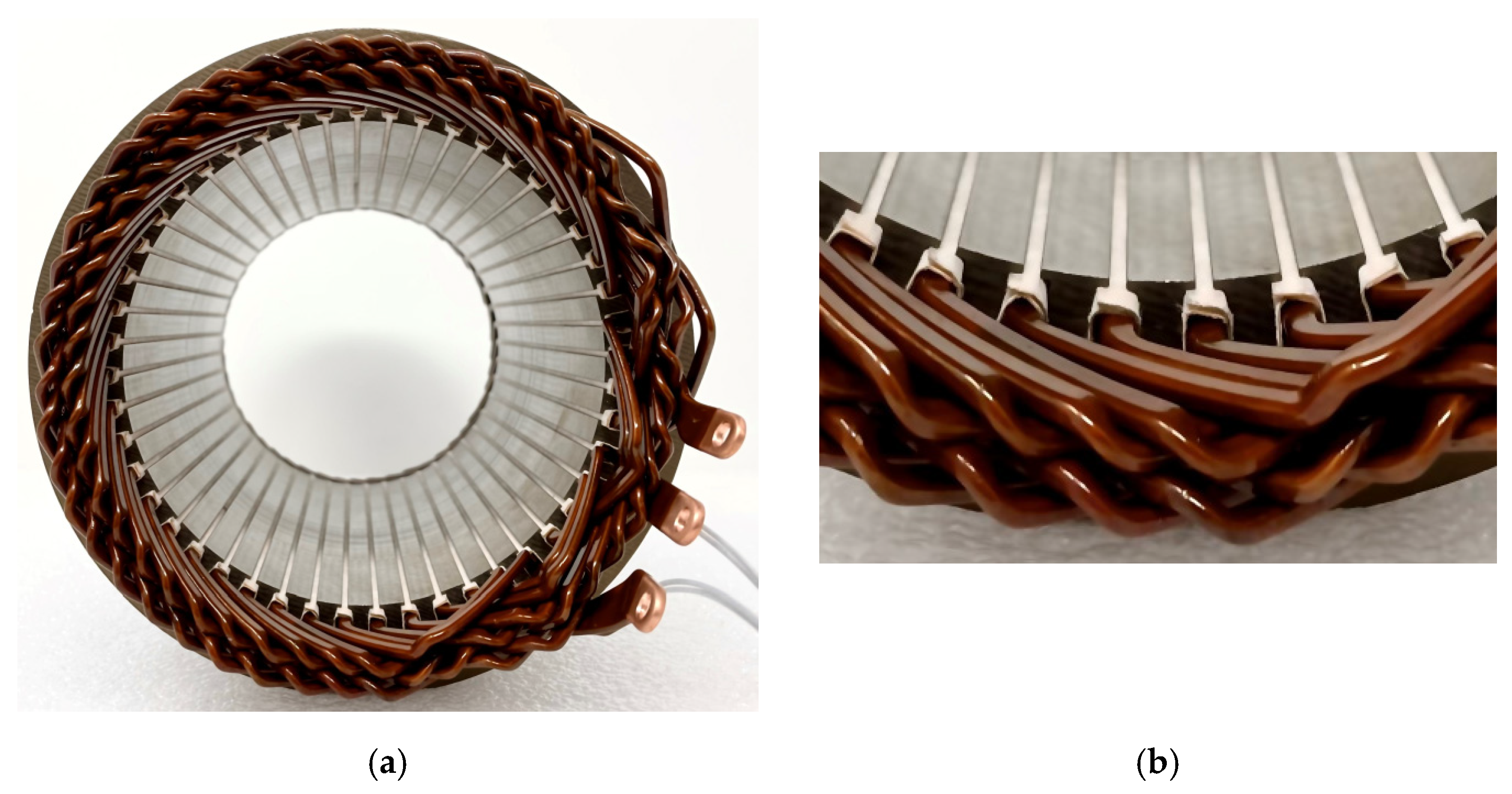
One so-called hairpin winding can be constructed from rectangular conductors, which are curved into a U-shape (as can be seen in Figure 2a) and inserted into the iron core slots. The ends of the windings are joined together (usually welded) on the other side of the iron core. For very high current windings, multiple insulated copper conductors can be printed in parallel upon the so-called Roebel transposition (see Figure 2b), thus improving the efficiency and other performances of high-power EMs [94,95].
Such windings have several advantages, e.g., a significantly increased fill factor (up to 0.7÷0.8), the feasibility of automated processing as well as AM, and good thermal performances due to the small amount of air between the conductors. Such distributed windings have shorter end-windings (and an inherently lower winding resistance) and do not come into contact with each other.
Therefore, more effective cooling systems (for example, in-slot water jackets) can be applied [98]. On the other hand, they have drawbacks, namely the low degree of flexibility with regard to winding designs limited by the reduced number of conductors per slot, substantial AC winding losses when operating at high-speed, and high manufacturing costs [88,99,100].
Hairpin windings are typically used in pretentious EMs. A typical example of a 3D printed hairpin stator winding manufactured at Additive Drives (Germany) is given in Figure 3 [101].
Upon such windings, a similar technology, namely plug-in windings, was proposed. Basically, a pair of hairpin windings are combined via male–female plug-in features. Although these windings are more easily automated manufactured, special measures have to be taken to join the two branches, and the resulting contact exhibits a high contact resistance [103,104].
AM enables the fabrication of non-conventional windings proposed for EMs of any level of complexity [105,106]. As a potential example, Figure 4 presents a special, radially displaced segmented laminated winding proposed by Reinap, A. in [105].

5. Additive Manufacturing of the Iron Cores

As noted, the possible use of AM technologies has had the lowest impact on the fabrication of the iron cores of the EMs, despite the great variety of utilizable ferromagnetic materials. Even if the above-mentioned prospective soft magnetic materials can be 3D printed in very thin layers (for example, via LOM technology), an insulating coating among them is needed to reduce the eddy current losses. This makes the use of AM technologies less attractive since it offers only two minor advantages: The possibility to construct rarely used, radially unsymmetrical iron cores and the elimination of the negative influence of punching, welding, and clamping over the traditional iron core stacks [50,107]. As a consequence, most of the practical realizations in the field of 3D printing of these iron cores are related to very small scale (moreover, demonstrative) EMs [108,109], and to axially flux PM ones [110].
As stated already, FeSi alloys with a high silicon content (up to 7%) are excellent materials for manufacturing iron cores of EMs. However, as the silicon content is increased by over 4.5% and the electric and magnetic properties (such as electrical resistivity, magnetic saturation, magneto-crystalline anisotropy, magnetostriction, etc.) are improved, the steel begins to brittle. Thus, punching technology cannot be applied, but the DMLS approach can solve this mechanical issue [111].
In [112], iron composite filaments were proposed for the fabrication of EMs’ iron cores. The very dense material must be sequentially 3D printed and sintered. It was demonstrated in the paper that the obtained material has high magnetic permeability. Unfortunately, the paper did not deal with the important iron losses.
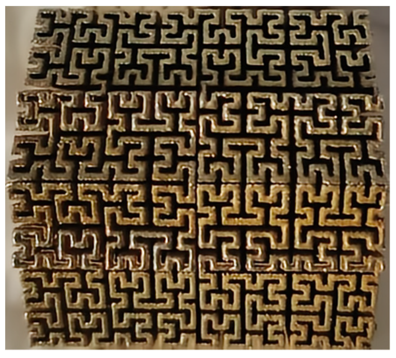
In [27], an innovative hollow-core transformer iron core made of silicon electrical steel alloys (Fe-3Si or Fe-6Si) was proposed. It was designed upon a certain Hilbert curve geometry, a continuous fractal space-filling curve (see Figure 5), and it can be exclusively fabricated by AM means, for example, SLM.
This construction idea can be extended to salient pole EMs, too. Even if the iron core losses were not reduced radically and the core volume was increased, the proposed structure has the potential of internal cooling the iron core legs.
By using the same manufacturing technology and Fe6Si powder, the iron core of an SRM was produced [113]. The obtained results showed greater iron core losses as compared with traditional construction made of laminations. These results are not relevant since the iron core was built up without insulating thin layers of the material and thus reducing eddy current losses. The paper only demonstrated the possibility of manufacturing iron cores using 3D printing.
Here, coreless PM rotor EMs should also be mentioned. Their rotor is comprised only of PMs and the potentially 3D-printed nonferrous (usually plastic) PM holders of any complexity. Such EMs have the advantage of not having iron losses (even at very high speeds) in the rotor, and not producing cogging torque, which increases the torque ripple. On the other hand, they have low torque/power density [114].

6. Additive Manufacturing of the Cooling Systems

Thanks to the optimized design of EMs, their speed and power density are pushed to their maximum limits. Therefore, a significant amount of heat is generated within them. The resulting thermal stress not only influences the performance of the EMs but also their lifespan. As a consequence, complicated cooling systems are required to maintain the internal temperature below its maximum allowable value [115]. Effective cooling is a challenging engineering task hampered by the closed waterproof housing, variable ambient temperatures, and humidity.
Conventional EMs are all air-cooled via a fan attached to the shaft and are equipped with housing fins to increase the convective cooling surface. This approach is inadequate for EMs applied in variable speed drives since, at low velocities, the fan does not guarantee the airflow required to cool the machine. In such cases, an independently driven radial fan is used. This method must also be applied for high-speed EMs since, at great velocities, the shaft-mounted fans are very noisy and account for a significant proportion of the developed torque.
This last method is not adequate for transportation applications since, due to the very limited amount of space under the hood of a vehicle, there is insufficient space for cooling fins on the housing and external cooling fans. For such applications, liquid cooling systems are the most efficient and widespread approaches. They consist of a pump, radiator, and assorted jackets or pipes within the housing of the EM. The heat generated is removed via the cooling agent that circulates through the jacket or pipes and passes through the radiator.
In terms of AM, cooling systems can bring about the most significant breakthrough in the field of EMs. Several older but very good designs of thermal management systems were infeasible due to their inability to be manufactured. 3D printing can enable the fabrication of specially shaped frames, cooling channels, and heat exchangers optimized for better thermal management of the EMs.

6.1. Hollow Winding Conductors

Conductor windings with a heat pipe or cooling channel in the middle of them, which can transport coolant fluids or gases, can ensure a good degree of direct local cooling of the windings. At higher currents, as in the case of high-power EMs, large cross-sections of hollow conductors are hard to shape as optimally required. However, by using AM, such conductors can be formed in any shape [51,116,117,118]. Obviously, although hollow conductors with the same active cross-section as their solid counterparts have a larger effective area, the current density in the windings can be multiplied as many as 3.5 times [119,120].

6.2. Direct Cooling of the Windings

AM enabled the global thermal performance of EMs to be improved by directly cooling the windings instead of optimizing the airflow inside the machine or of the active convective cooling surface of the frame [121].
Designers can make use of two of the basic benefits of diverse AM technologies. On the one hand, tubes with walls as thin as 60 μm can be produced, which enables the fabrication of coolers of low masses and volumes but with huge convective cooling surfaces, and hollow structures of any degree of complexity through which the cooling agent can flow [10]. On the other hand, AM technologies support the manufacturing of the coolers implemented in special thermally conductive electrical insulators, which are hard to process using conventional methods [122]. These materials must not only exhibit high thermal conductivities but also still be good electrical insulators with high dielectric strength. Moreover, they must be non-magnetic and corrosion-resistant [123,124,125]. The selection of the most suitable material in each cooling system has a significant influence on the thermal management of EMs.
Both the end-windings and the coil branches inside the slots can be cooled directly by applying new, possibly 3D-printed components made of such materials. These cooling methods are very effective since the cooling surfaces are very close to the heat sources (the windings).
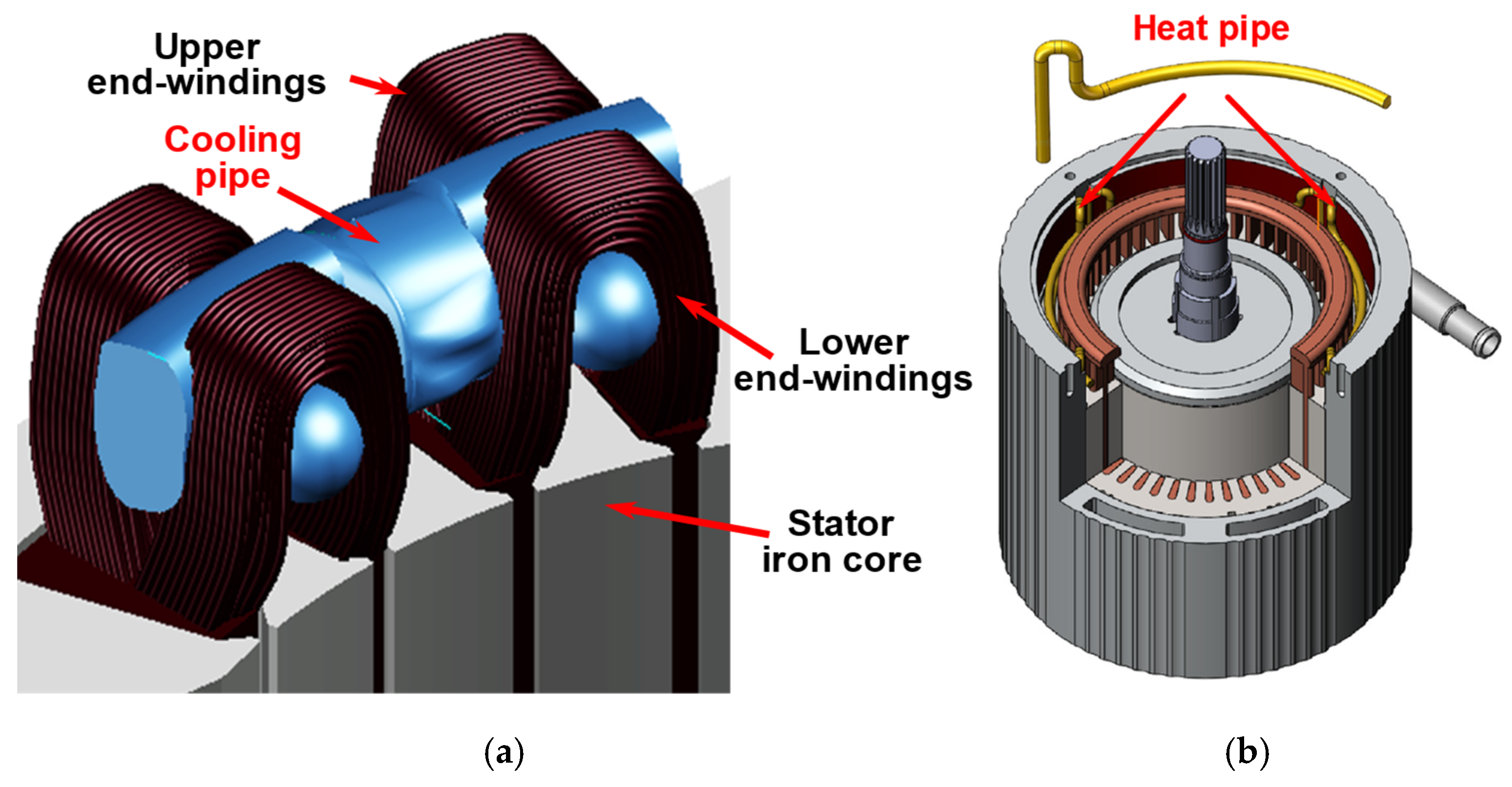
In [126], a specially shaped duct is presented, which is placed through the end-windings and circulates a coolant agent (as can be seen in Figure 6a). In another approach, a micro-structured heat pipe surrounds the end-windings of an experimental permanent magnet synchronous machine (PMSM), as shown in Figure 6b [127]. Both technical solutions have the advantage of increasing the cooling efficiency without increasing the volume of the EM.
By using 3D-printing techniques, cooling ducts effectively surround the windings, and even more complicated shapes with very thin walls can be manufactured [127,128,129].
By applying another approach, particularly formed thermally conductive parts, which effectively serve as heat exchangers with a large active cooling surface, can be inserted in the EMs to surround the concentrated windings, especially the ends of the coils. The extra parts ensure a larger contact surface among the coils of the housing. This concept is suitable in terms of both cooling by traditional airflows and liquid cooling jackets [130]. The optimized shape of the cooling insert can only be effectively manufactured by employing 3D printing.
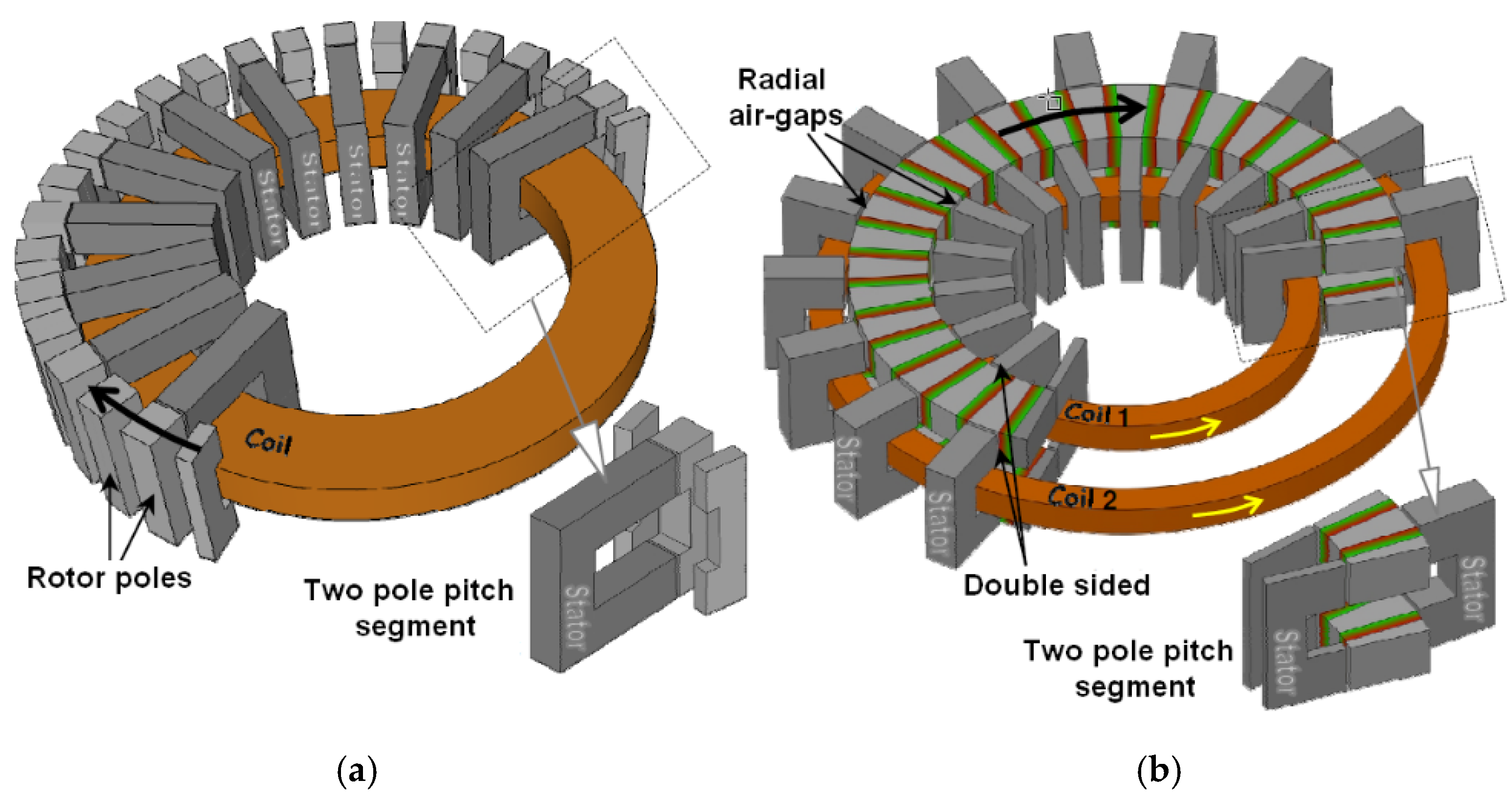
A great variety of technical solutions have been proposed in the literature that adopts the so-called in-slot cooling approach. Most typically, this can be applied to EMs with concentrated windings, where a space between the coils is found in their slots, mainly for insulation purposes (see the blue areas in Figure 7).
By applying the simplest approach, these gaps can be filled with specifically shaped thermally conductive insulating materials, which can exhibit much greater thermal conductivity than air [131]. Improved cooling can be achieved if a heat exchanger is placed in the available space, even if the EM is only cooled by the fan and the fins on the housing.
In the slots, among the turns, 3D-printed cooling channels with very thin walls also can be placed, as can be seen in Figure 8a [132,133,134]. In [135], H. Yin proposed to place a two-way thin copper pipeline in the slots of a PMSM, as shown in Figure 8b. By applying this relatively simple pipe arrangement, called an internal water cooling (IWC) system, effective thermal management of the PMSM was ensured.
Wrobel and Hussein [136] placed small, optimally designed, 3D-printed so-called heat guides in these free spaces inside the slots. Both solutions profoundly contributed to increasing the extent to which the coils are cooled.
Figure 8. In-slot cooling approaches. (a) Liquid cooling channel in the slot of the EM [137]; (b) two-way copper pipeline placed in the slots of a PMSM, reproduced with permission from [135]. Copyright the authors 2018.
Machines 10 00330 g008
Another achievement of AM (as well PBF and SLM in particular) is enabling the fabrication of small-scale heat exchangers consisting of complex internal geometries with a large surface area density (that is, having a very large active surface but a small volume) with regard to low-density materials, which cannot be manufactured using conventional technologies [138]. By integrating heat exchangers into the EMs, their cooling capability can be significantly improved.
W. Sixel et al. proposed an innovative thermal management system consisting of polycarbonate-aluminum flake composite pieces placed between the concentrated coils of an EM. Each component contains three cooling channels. All the ends of the cooling pieces are connected to a common, 3D-printed liquid-cooled heat exchanger [139].
A more demanding direct winding cooling solution was proposed in [140]. Rectangular microfeature-enhanced flat heat exchangers (with the fine structure shown in Figure 9) can be inserted inside the windings. These are washed by the cooling fluid in the axial direction of the machine. Due to their innovative large surface structure, they exhibit a huge heat transfer coefficient, approximately 30 kW/(m2·K). The special non-conductive material produced, which can be the basis for the manufacturing of microchannels, can be 3D printed by applying DMLS [141]. However, this method also has some drawbacks, as a high pumping pressure is required and only the windings are cooled [88].
As coils can be 3D printed layer-by-layer, the concept of integrating the cooling channels inside the windings can be achieved [63]. The increase in the coil volume due to the inside channels is compensated for by the application of very high current densities (over 100 A/mm2). The diameter and position of the channels must be optimized in a way that ensures the current density distribution over the entire cross-section of the coil is uniform.

6.3. Cooling the Iron Core

The iron cores within EMs can also be directly cooled by heat exchangers and cooling jackets.
A large proportion of EMs is cooled by a closed-loop liquid cooling system, which usually consists of a cooling jacket around the machine housing in direct contact with the iron core, arranged in numerous ways, and using various coolants [138]. Such cooling jackets can consist of squirrel-cage or serpentine duct structures [115,142]. Further optimization of such cooling systems is limited by the classical manufacturing techniques and traditional thermally conductive materials available. However, AM can also bring about significant advancements in this case since it enables structures of practically any shape to be fabricated (toroidal, axial, helical, circumferential, serpentine pipes) with new, advanced materials.
Materials with extremely high thermal conductivities can be applied in such thermal management systems. These can contribute to enhancing the cooling performance and reducing the mass of the cooling system, which are both important issues in automotive applications.
Besides these benefits, another significant advantage of 3D-printed cooling jackets is the reduced likelihood of them leaking due to their mechanical integrity since, rather than being assembled from different components, they are manufactured as a single unit [50].
The cooling jacket surrounding the outer side of the iron core of the EM can similarly be extended to penetrate the iron core, and also serve as a flux barrier in the yoke of the stator iron core, as it was proposed for a segmented stator PMSM by A. Nollau and D. Gerling in [143]. In this case, the cooling jacket not only cools the iron core, but also magnetically separates the stator modules of the machine.
In [144], an axial heat exchanger fabricated by employing a metal AM has been proposed for an outer rotor EM with concentrated windings, which does not have end-windings. The heat exchanger, as can be seen in Figure 10, is placed around the shaft and is in thermal contact with the yoke of the stator iron core. The air flowing axially through the machine cools the heat exchanger as well as the iron core indirectly.

6.4. The Housing and the Cooling Fan

Although the housing of EMs seems to be the simplest part of an EM, it plays a crucial role in terms of cooling and protecting the interior of the EM and assuring its required rigidity. All of these are achieved by the smallest mass and at the minimum cost. Furthermore, in the case of housing, AM can bring about significant improvements.
In Figure 11, a relevant example of the possible complexity of a 3D-printed housing of an electric traction system is presented. The topologically optimized design, as well as the use of the most advanced materials and AM technologies, enabled the mass of the housing to be reduced by 40%. The innovative honeycomb structure of the surface not only increased the active cooling surface but also the rigidity of the housing at a minimal mass [145].
The cooling fan of an EM is also a simple, albeit essential, component. It must be optimized to achieve maximum airflow efficiency as well as minimum mass and noise. Until recently, its optimization was significantly limited by the materials available and manufacturing technologies.
As is the case with other components of an EM, further improvement of the fan and blades, in particular, was catalyzed by the multitude of potentials of AM technologies. The reduction in the mass of this part helps to reduce the total weight of the EM and increase its overall performance.
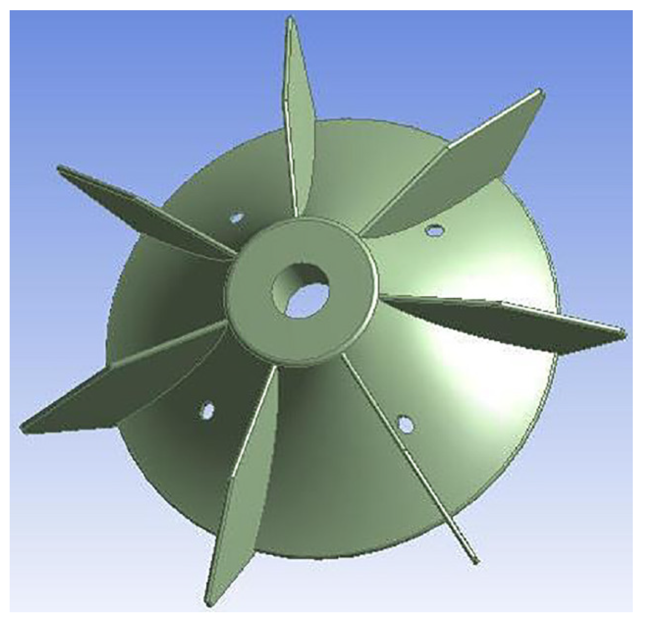
Diverse fan blades enhanced by laser sintering can be fabricated, as is shown in Figure 12. The excellent thermomechanical properties of the low-density polyamide powder from which the blades are produced are the key to their increased performance.

7. Representative and Potential Examples of Using 3D Printing in the Fabrication of Electric Machines

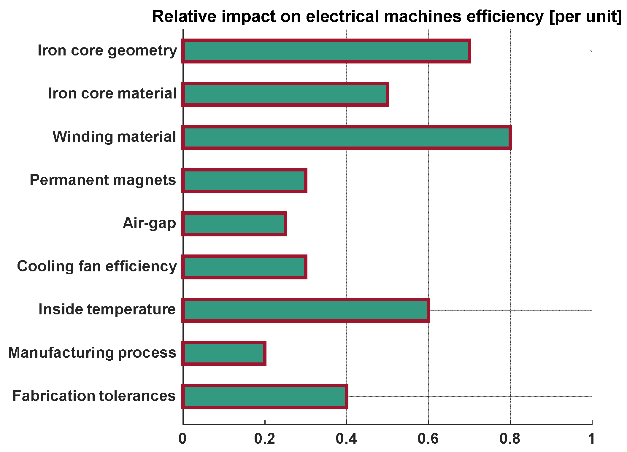
For EMs, the power/torque density and efficiency are the two key performance indicators that can be enhanced by improving any of the components of EMs. In Figure 13, the influence of a diverse range of possible advancements with regard to increasing the efficiency of EMs is presented [67].
Over recent years, leading scientific journals have been overwhelmed with papers concerning the use of diverse AM technologies concerning essentially all the matters mentioned in Figure 13. In the following section, the most significant achievements will be surveyed.

7.1. Permanent Magnet Synchronous Machines

PMSMs, being highly efficient and as a result of their great specific power and torque, are preferred in numerous industrial and automotive applications [148,149,150].
AM can contribute to reductions in the mass, volume, and inertia of the rotors of such machines. As was reported in [151], by introducing optimized gaps, holes, smaller cavities, and lattice structures into a PMSM rotor, the moment of inertia was reduced by 23% without sacrificing its mechanical strength.
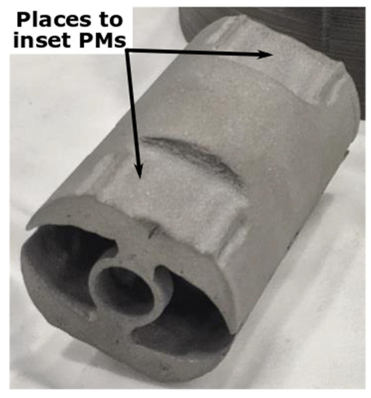
Furthermore, by applying this manufacturing technology, the PMs can be excellently fitted in special places, as can be seen in Figure 14 [152]. Therefore, the likelihood of the PM detaching is low, even in the case of high-speed EMs.
In [153], a spoke-type PM was reported. Among EMs, this is considered to exhibit one of the greatest power densities as its maximum power is 125 kW at 12,000 r/min with a mass of just 14 kg. This was achieved mainly due to the 3D-printed direct oil cooling of the stator, combined with the forced air cooling of the rotor. The single-piece cooling system is comprised of very thin walls and an optimized fine active surface.
Furthermore, axial flux PMSMs are proposed for light traction applications. Their high torque density is counterbalanced by more complicated structures, which also require fabrication using AM technologies [154].
AM empowers specialists to design PMs of practically any shape for PMSMs. In [155], PMs with a sinusoidal-shaped surface fabricated by CS technology are proposed. It was demonstrated that both the harmonic content in the induced electromotive force (EMF) and the cogging torque were appreciably reduced.

7.2. Induction Machines

Without a doubt, IMs dominate the EM market, mainly due to their simple and robust construction, low maintenance requirements, and affordable cost [156]. Even though their manufacturing technology has been well-established for many decades, AM can also lead to new approaches in this field.
Advanced AM technologies enable the 3D printing of multiple diverse materials simultaneously. By taking into consideration this advantage, Chinthavali [157] demonstrated that the entire squirrel-cage rotor can be fabricated within a single processing stage.
The CS AM method can also bring about improvements in the field of high-speed IMs, where the construction of robust rotors is the main bottleneck. If this technology is used for the fabrication of solid rotors, very good diffusion bonding between the iron core and the copper layer that covers it can be achieved, which prevents the covering from detaching [61].

7.3. Synchronous Reluctance Machines

Over recent years, SyncRels have become very serious competitors of IMs due to their passive rotor and high efficiency [158]. To achieve significant levels of performance, their rotor must be optimized, resulting in complicated structures with diverse forms of flux guides and barriers [159,160]. Due to the technical limitations of laminated punching, in numerous cases, the rotor iron core could not be fabricated exactly as determined from the optimization. Moreover, these rotors cannot be used in high-speed applications due to the mechanical limitations of the low-rigidity rotor structures.
Although PM-assisted SyncRels, which have frequently been investigated over recent years, have PMs placed in the flux barriers of complex shapes, it is difficult to acquire PMs of any specific shapes.
These drawbacks of SyncRels can be overcome by applying diverse AM technologies [161]. The 3D printing of both the iron cores and PMs of any shape by SLM and FDM has been thoroughly investigated [162,163].
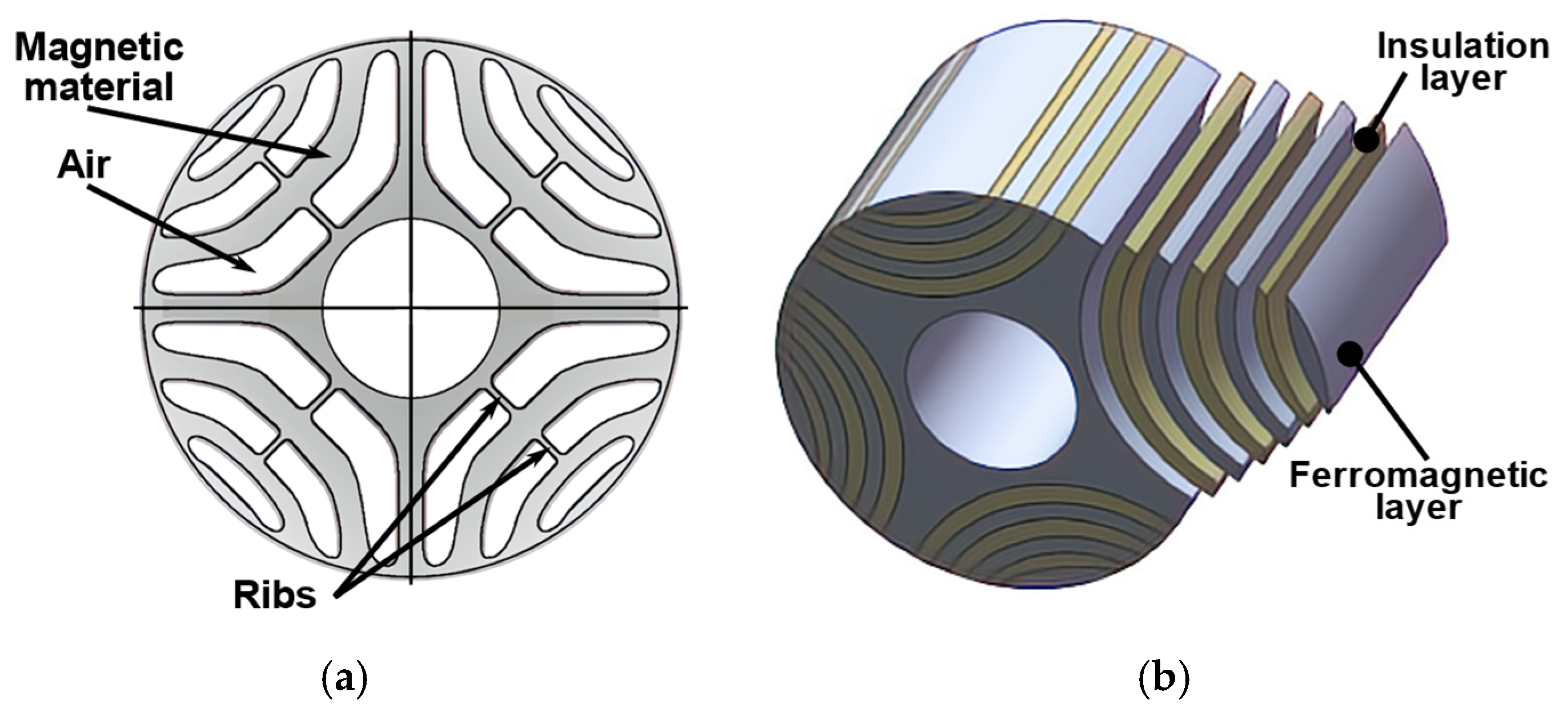
A significant drawback of SyncRels that operate at high speeds is the necessity to place so-called ribs to rigidize the flux bridges, as can be seen in Figure 15a [160,164]. These small zones diminish the magnetic properties of these EMs. This disadvantage can be eliminated by applying dual-phase magnetic components for the construction of the iron core, which can be processed utilizing AM technologies. These magnetic materials have the remarkable property that certain regions (in this case, those corresponding to the ribs) can be locally treated via a nitriding process to transform them into non-magnetic zones [165].
A higher saliency ratio (Ld/Lq) can be obtained in the case of the SyncRels with axially laminated anisotropic (ALA) rotors, as shown in Figure 15b [168,169]. However, both structures are difficult and expensive to manufacture when employing traditional punched lamination technology since numerous, differently sized laminations are required. Furthermore, in the case of the sandwiched rotor, the designer must deal with the different thermal expansion coefficients of aluminum and iron, while in the case of topology, extra bending of the laminations is required. Concerning the manufacture of both structures, AM can be a source of significant stimuli.

7.4. Switched Reluctance Machines

SRMs are also competitive candidates for the EMs used in variable speed applications, mainly due to their simple and robust construction [170,171]. Having two basic drawbacks (high torque ripples and noise), their structure was frequently optimized to address these disadvantages. In several cases, the optimized structure could not be processed via traditional methods [172].
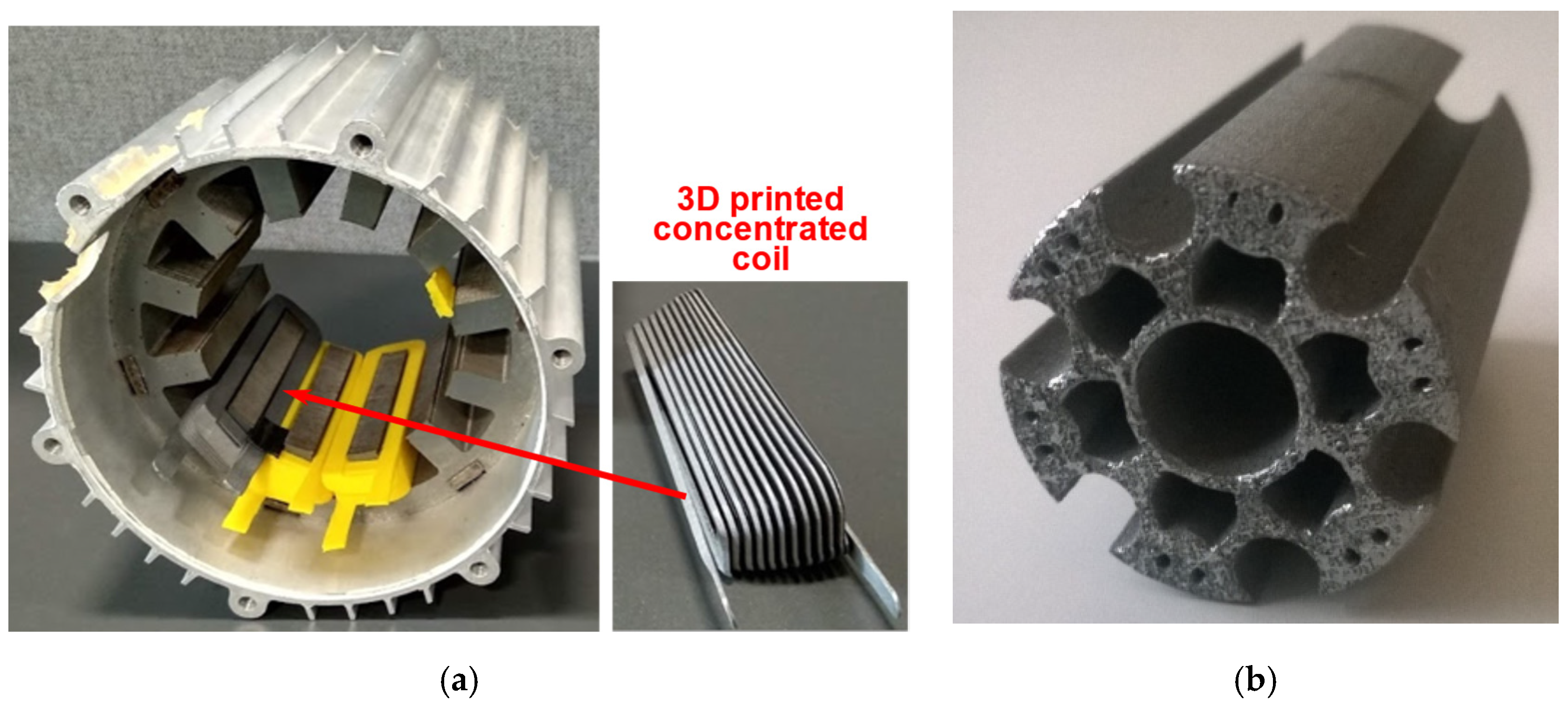
AM has also brought about important breakthroughs in the case of SRMs, too. Laser PBF-fabricated concentrated coils (similar to those seen in Figure 1) can be used on the stator of the SRMs, as is shown in Figure 16a. 3D printing can also bring advancements in the case of the SRM rotors. Given that the complex optimized rotor structure proposed in [172] and presented in Figure 16b has several notches and holes, both low mass and inertia were achieved. Additionally, the rotor can be easily cooled by the air passing through the machine. It was fabricated by employing an SLM of an Fe-Co alloy [32].
By using any AM technology, continuous rotor skewing can be easily solved for any type of EM. This issue is very important in the case of SRMs, which exhibit high torque ripples.
These new manufacturing technologies simply enable even small components to be added to the traditional machine structure. In [173], small ribs were placed between the 3D-printed rotor poles of an SRM to collect the leakage fluxes and thus reduce losses. The ribs must be sufficiently small so as to not influence the inertia of the rotor, but still mechanically hard to withstand the great forces they are subjected to at high speeds. Therefore, a rigid honeycomb structure was selected.

7.5. Construction of Special Electrical Machines

Several unconventional EMs are in use (customarily with complex structures and magnetic flux paths), e.g., flux modulation, flux switching, transverse flux, claw-pole machines, etc., all of which are difficult and expensive to manufacture using traditional methods but are suitable for use with AM [50,174].
Perhaps the most complex among them is transverse flux machines (TFMs). Given their performance, they could be an excellent solution for direct-drive electric traction applications since their torque density is very high and their rated speed is low since they can be constructed with a great number of poles. The elimination of the gearbox increases both their efficiency and reliability while lowering the overall cost of the entire drivetrain. In turn, since their power factor is low, converters of increased power are required [175,176]. However, the main drawback of TFMs is their very complex structure, as can be seen in Figure 17 [177].
As has already been stated, new AM technologies have been envisaged by design engineers. Specialists eliminating the limitations of traditional fabrication technologies and materials have proposed several EMs of intriguing topologies offering superior levels of performance.
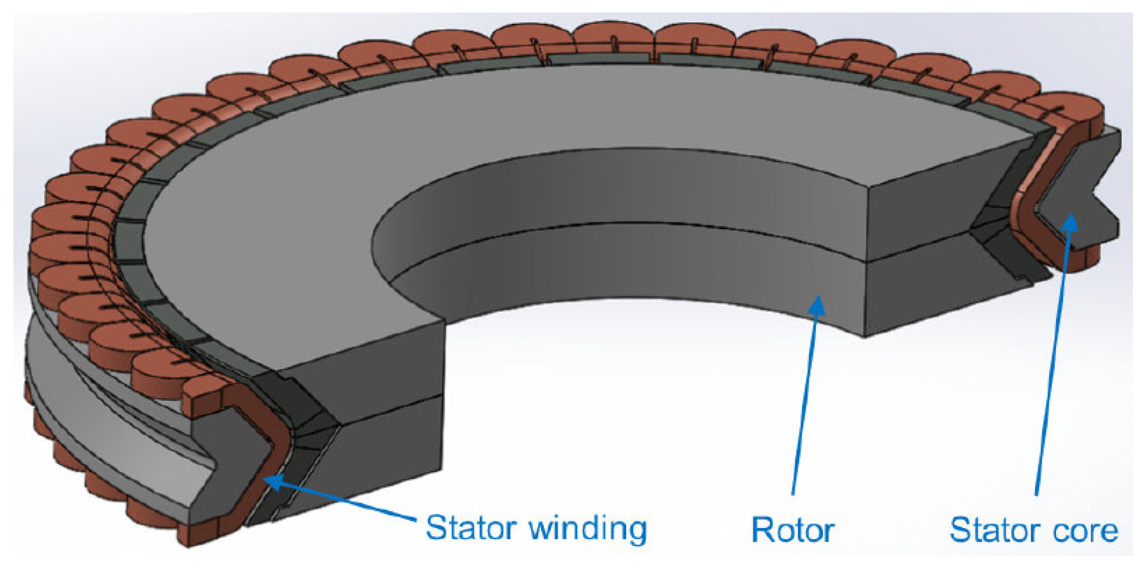
In [179], a dual-conical (hourglass-shaped) air-gap PMSM was proposed and investigated (see Figure 18). The machine, which weighs 40 kg, can produce 112 kW of power at 3750 r/min. Due to liquid cooling, its admitted current density is 23 A/mm2. The uncommon structure consists of a large air-gap surface, and the magnetic flux passes through it along true 3D paths. This is the “secret” of both its high-power density (twice that of traditional machines) and efficiency.
It is obvious that this EM of an unusual shape cannot be fabricated by employing traditional technologies. Its iron cores were 3D printed using CS technology [180]. The stator windings were made of rectangular cross-sectional conductors to achieve a high slot fill factor. Such windings could also be produced via AM technologies.
The aforementioned cases are just few examples of the multitude of EM proposals that could be exclusively fabricated using AM technologies.

8. Conclusions

As can be seen, a great variety of AM technologies can be used for the fabrication of a diverse range of (partially novel) components and variants of EMs. Finally, the advantages, drawbacks, and future of implementing AM technologies in the field of EMs should be summarized.
Designers of EMs can make use of several advantages concerning the 3D printing of diverse components of EMs. The complexity of newly developed EM structures is practically unlimited. It may not be possible, or is at least extremely hard, to fabricate the shapes of the designed components by conventional, subtractive, or powder metallurgical manufacturing methods. 3D printing enables different EM parts to be built simultaneously, avoiding the need for them to be assembled later.
Some EM components can be fabricated with mixed materials, even of different types (conductors with insulators, iron cores with heating pipes, structural components with thermal management components, etc.). By using AM technologies, it is possible to vary the composition of iron cores in such a way that their properties can be tuned to suit the requirements of a certain type of EM. Continuous rotor skewing can be achieved by 3D printing, which is the key to reducing the torque ripple of most EMs.
The impact of AM on the development of diverse types of EMs is different, mainly due to the complexity of the materials and structures used. In Table 2, the impact scores for the different parts of the most typical EM fabricated by using AM are provided. As in the case of Table 1, the scores here also range from 1 (poor) to 5 (excellent).
As can be seen from the table, for the most widely used low-power IM with a well-established structure and manufacturing technology, the new manufacturing technologies and materials are the least likely to be applied. As the complexity of EMs increases, so does the need for additive manufacturing of their key components. 3D printing has the greatest potential in the case of special EMs with outstanding topologies.
Most of the 3D printing processes do not result in considerable scratches, so material losses of close to zero can be achieved. It is also possible to reduce the usage of raw materials by designing EMs without excessive amounts of material. By only placing ferrous material where the magnetic flux must pass (for example, by modularizing the iron cores [181]), the other parts of the stator or rotor can be manufactured from non-magnetic materials, which are cheaper and of lower density. Therefore, both the price of the EM and iron core losses can be decreased, while its power/torque density increases. This approach can be predominantly beneficial in the case of rotors since their mass and inertia can be reduced, while the dynamic characteristics of EMs improved [182]. Moreover, the segmented parts can more easily be decommissioned and recycled [183].
These material savings are in line with the Circular Economy Action Plan (CEAP) adopted by the European Commission in March 2020 [184]. This is one of the main constituents of the European Green Deal, Europe’s new agenda for sustainable growth, but it conforms with other regulations around the world concerning the reduction in the footprint of EMs [185].
All the above aspects facilitate the development of EMs being better suited to the given applications with increased manufacturability, efficiency, and power/torque density [50].
On the other hand, some limitations of these new technologies can be mentioned. Despite the intensive level of research conducted, AM technology has not yet become fully mature. Consistently, countless improvements are reported concerning the technologies themselves (manufacturing speed, finishing, etc.), the applied materials, and, of course, costs. These all surely will contribute to the widespread growth of 3D printing technologies in the manufacturing of different EM parts.
Currently, 3D printing is only revolutionizing the prototyping and very-small-series production of EMs since no expensive special-purpose tools are needed. The main advances in terms of the fabrication of cooling systems were achieved, which has a significant impact on the performance of all EMs.
The complete manufacturing of EMs exclusively by AM technologies without any need for assembly or post-processing during or after 3D printing seems futuristic, although some attempts have been reported albeit only for demonstrative purposes [186].
Finally, it can be concluded that given the forecasted and expected enhancements in AM, this new manufacturing technology will gain more and more ground, and the performances of EMs could be considerably enhanced. New designs of EMs of a high degree of complexity and customization are also expected soon [187].

Funding

This work was supported in part by the TKP2020-NKA-10 Project through the 2020-4.1.1-TKP2020 Thematic Excellence Program by the National Research, Development and Innovation Fund of Hungary; in part by ZalaZONE Automotive Proving Ground Zala Ltd.; and in part by the Ministry of Innovation and Technology National Research, Development and Innovation (NRDI) Office within the framework of the Autonomous Systems National Laboratory Program.

Institutional Review Board Statement

Not applicable.

Informed Consent Statement

Not applicable.

Data Availability Statement

Not applicable.

Conflicts of Interest

The authors declare no conflict of interest.

References

  1. Global Electric Motor Market Report 2021–2030: Development of High Power-to-Weight Ratio Electric Motors Gaining Momentum. Available online: https://www.globenewswire.com/news-release/2021/12/20/2355052/28124/en/Global-Electric-Motor-Market-Report-2021-2030-Development-of-High-Power-to-Weight-Ratio-Electric-Motors-Gaining-Momentum.html (accessed on 27 January 2022).
  2. Cheng, M.; Chan, C. General Requirement of Traction Motor Drives. In Encyclopedia of Automotive Engineering; Crolla, D., Foster, D.E., Kobayashi, T., Vaughan, N.D., Eds.; Wiley: Chichester, UK, 2014; pp. 1–18. [Google Scholar]
  3. Dorrell, D.G. A review of the methods for improving the efficiency of drive motors to meet IE4 efficiency standards. J. Power Electron. 2014, 14, 842–851. [Google Scholar] [CrossRef] [Green Version]
  4. Cantwell, J.; Hayashi, T. Paradigm Shift in Technologies and Innovation Systems; Springer Nature: Singapore, 2019. [Google Scholar]
  5. Conner, B.P.; Manogharan, G.P.; Martof, A.N.; Rodomsky, L.M.; Rodomsky, C.M.; Jordan, D.C.; Limperos, J.W. Making sense of 3D printing: Creating a map of additive manufacturing products and services. Addit. Manuf. 2014, 1–4, 64–76. [Google Scholar] [CrossRef]
  6. Tiismus, H.; Kallaste, A.; Belahcen, A.; Tarraste, M.; Vaimann, T.; Rassõlkin, A.; Asad, B.; Shams Ghahfarokhi, P. AC magnetic loss reduction of SLM processed Fe-Si for additive manufacturing of electrical machines. Energies 2021, 14, 1241. [Google Scholar] [CrossRef]
  7. ISO/ASTM 52900-15; Additive manufacturing—General principles—Terminology. ASTM International: West Conshohockeas, PA, USA, 2015.
  8. MacDonald, E.; Wicker, R. Multiprocess 3D printing for increasing component functionality. Science 2016, 353, aaf2093. [Google Scholar] [CrossRef] [PubMed]
  9. Razavykia, A.; Brusa, E.; Delprete, C.; Yavari, R. An overview of additive manufacturing technologies—A review to technical synthesis in numerical study of selective laser melting. Materials 2020, 13, 3895. [Google Scholar] [CrossRef]
  10. Tiismus, H.; Kallaste, A.; Vaimann, T.; Rassõlkin, A.; Belahcen, A. Electrical resistivity of additively manufactured silicon steel for electrical machine fabrication. In Proceedings of the Electric Power Quality and Supply Reliability Conference (PQ 2019) & Symposium on Electrical Engineering and Mechatronics (SEEM 2019), Kärdla, Estonia, 12–15 June 2019. [Google Scholar] [CrossRef] [Green Version]
  11. Pfaff, A.; Jäcklein, M.; Hoschke, K.; Wickert, M. Designed materials by additive manufacturing—Impact of exposure strategies and parameters on material characteristics of AlSi10Mg processed by laser beam melting. Metals 2018, 8, 491. [Google Scholar] [CrossRef] [Green Version]
  12. Kafle, A.; Luis, E.; Silwal, R.; Pan, H.M.; Shrestha, P.L.; Bastola, A.K. 3D/4D Printing of polymers: Fused deposition modelling (FDM), selective laser sintering (SLS), and stereolithography (SLA). Polymers 2021, 13, 3101. [Google Scholar] [CrossRef]
  13. Demir, A.G.; Previtali, B. Multi-material selective laser melting of Fe/Al-12Si components. Manuf. Lett. 2017, 11, 8–11. [Google Scholar] [CrossRef]
  14. Kocsis, B.; Fekete, I.; Varga, L. Metallographic and magnetic analysis of direct laser sintered soft magnetic composites. J. Magn. Magn. Mater. 2020, 501, 166425. [Google Scholar] [CrossRef]
  15. Dass, A.; Moridi, A. State of the art in directed energy deposition: From additive manufacturing to materials design. Coatings 2019, 9, 418. [Google Scholar] [CrossRef] [Green Version]
  16. Wong, K.V.; Hernandez, A. A review of additive manufacturing. ISRN Mech. Eng. 2012, 2012, 208760. [Google Scholar] [CrossRef] [Green Version]
  17. Gokuldoss, P.K.; Kolla, S.; Eckert, J. Additive manufacturing processes: Selective laser melting, electron beam melting and binder jetting—Selection guidelines. Materials 2017, 10, 672. [Google Scholar] [CrossRef] [PubMed] [Green Version]
  18. Najmon, J.C.; Raeisi, S.; Tovar, A. Review of additive manufacturing technologies and applications in the aerospace industry. In Additive Manufacturing for the Aerospace Industry; Froes, F., Boyer, R., Eds.; Elsevier: Amsterdam, The Netherlands, 2019; pp. 7–31. [Google Scholar]
  19. Zakeri, S.; Vippola, M.; Levänen, E. A comprehensive review of the photopolymerization of ceramic resins used in stereolithography. Addit. Manuf. 2020, 35, 101177. [Google Scholar] [CrossRef]
  20. Huang, J.; Qin, Q.; Wang, J. A review of stereolithography: Processes and systems. Processes 2020, 8, 1138. [Google Scholar] [CrossRef]
  21. Jiménez, A.; Bidare, P.; Hassanin, H.; Tarlochan, F.; Dimov, S.; Essa, K. Powder-based laser hybrid additive manufacturing of metals: A review. Int. J. Adv. Manuf. Technol. 2021, 114, 63–96. [Google Scholar] [CrossRef]
  22. Pham, T.; Kwon, P.; Foster, S. Additive manufacturing and topology optimization of magnetic materials for electrical machines—A review. Energies 2021, 14, 283. [Google Scholar] [CrossRef]
  23. Krings, A.; Boglietti, A.; Cavagnino, A.; Sprague, S. Soft magnetic material status and trends in electric machines. IEEE Trans. Ind. Electron. 2017, 64, 2405–2414. [Google Scholar] [CrossRef]
  24. Naseer, M.U.; Kallaste, A.; Asad, B.; Vaimann, T.; Rassãlkin, A. A review on additive manufacturing possibilities of electrical machines. Energies 2021, 14, 1940. [Google Scholar] [CrossRef]
  25. Sarap, M.; Kallaste, A.; Ghahfarokhi, P.S.; Tiismus, H.; Vaimann, T. Determining the thermal conductivity of additively manufactured metal specimens. In Proceedings of the 29th International Workshop on Electric Drives: Advances in Power Electronics for Electric Drives (IWED 2022), Moscow, Russia, 26–29 January 2022. [Google Scholar]
  26. Lamichhane, T.N.; Sethuraman, L.; Dalagan, A.; Wang, H.; Keller, J.; Paranthaman, M.P. Additive manufacturing of soft magnets for electrical machines—A review. Mater. Today Phys. 2020, 15, 100255. [Google Scholar] [CrossRef]
  27. Plotkowski, A.; Carver, K.; List, F.; Pries, J.; Li, Z.; Rossy, A.M.; Leonard, D. Design and performance of an additively manufactured high-Si transformer core. Mater. Des. 2020, 194, 108894. [Google Scholar] [CrossRef]
  28. Stornelli, G.; Faba, A.; Di Schino, A.; Folgarait, P.; Ridolfi, M.R.; Cardelli, E.; Montanari, R. Properties of additively manufactured electric steel powder cores with increased Si content. Materials 2021, 14, 1489. [Google Scholar] [CrossRef] [PubMed]
  29. Mikler, C.; Chaudhary, V.; Borkar, T.; Soni, V.; Jaeger, D.; Chen, X.; Contieri, R.; Ramanujan, R.; Banerjee, R. Laser additive manufacturing of magnetic materials. JOM 2017, 69, 532–543. [Google Scholar] [CrossRef] [Green Version]
  30. Schönrath, H.; Spasova, M.; Kilian, S.; Meckenstock, R.; Witt, G.; Sehrt, J.; Farle, M. Additive manufacturing of soft magnetic permalloy from Fe and Ni powders: Control of magnetic anisotropy. J. Magn. Magn. Mater. 2019, 478, 274–278. [Google Scholar] [CrossRef]
  31. Ding, C.; Liu, L.; Mei, Y.; Ngo, K.D.; Lu, G.-Q. Magnetic paste as feedstock for additive manufacturing of power magnetics. In Proceedings of the 2018 IEEE Applied Power Electronics Conference and Exposition (APEC 2018), San Antonio, TX, USA, 4–8 March 2018; pp. 615–618. [Google Scholar] [CrossRef]
  32. Metsä-Kortelainen, S.; Lindroos, T.; Savolainen, M.; Jokinen, A.; Revuelta, A.; Pasanen, A.; Ruusuvuori, K.; Pippuri, J. Manufacturing of topology optimized soft magnetic core through 3D printing. In Proceedings of the NAFEMS Exploring the Design Freedom of Additive Manufacturing through Simulation, Helsinki, Finland, 22–23 November 2016. [Google Scholar]
  33. Schmool, D.; Markó, D. Magnetism in Solids: Hysteresis. In Reference Module in Materials Science and Materials Engineering; Hashmi, S., Ed.; Elsevier: Amsterdam, The Netherlands, 2018. [Google Scholar]
  34. Chaudhary, V.; Mantri, S.A.; Ramanujan, R.V.; Banerjee, R. Additive manufacturing of magnetic materials. Prog. Mater. Sci. 2020, 114, 100688. [Google Scholar] [CrossRef]
  35. Szabó, L.; Viorel, I.A.; Iancu, V.; Popa, D.C. Soft magnetic composites used in transverse flux machines. Oradea Univ. Ann. Electrotech. Fascicle 2004, 134–141. [Google Scholar]
  36. Pham, T.Q.; Do, T.T.; Kwon, P.; Foster, S.N. Additive manufacturing of high performance ferromagnetic materials. In Proceedings of the Energy Conversion Congress and Exposition (ECCE 2018), Portland, OR, USA, 23–27 September 2018; pp. 4303–4308. [Google Scholar] [CrossRef]
  37. Pyo, H.-J.; Jeong, J.W.; Yu, J.; Lee, S.G.; Kim, W.-H. Design of 3D-printed hybrid axial-flux motor using 3D-printed SMC core. IEEE Trans. Appl. Supercond. 2020, 30, 5202004. [Google Scholar] [CrossRef]
  38. Goll, D.; Schuller, D.; Martinek, G.; Kunert, T.; Schurr, J.; Sinz, C.; Schubert, T.; Bernthaler, T.; Riegel, H.; Schneider, G. Additive manufacturing of soft magnetic materials and components. Addit. Manuf. 2019, 27, 428–439. [Google Scholar] [CrossRef]
  39. Benack, N.C.; Wang, T.; Matthews, K.; Taheri, M.L. Additive manufacturing methods for soft magnetic composites (SMCs). Microsc. Microanal. 2018, 24, 1066–1067. [Google Scholar] [CrossRef] [Green Version]
  40. Kong, F.; Chang, C.; Inoue, A.; Shalaan, E.; Al-Marzouki, F. Fe-based amorphous soft magnetic alloys with high saturation magnetization and good bending ductility. J. Alloy. Compd. 2014, 615, 163–166. [Google Scholar] [CrossRef]
  41. Enomoto, Y.; Tokoi, H.; Imagawa, T.; Suzuki, T.; Obata, T.; Souma, K. Amorphous motor with IE5 efficiency class. Hitachi Rev. 2015, 64, 480–487. [Google Scholar]
  42. Cepoi, R.D.; Jaşcău, F.F.; Szabó, L. Current trends in energy efficient electrical machines. J. Electr. Electron. Eng. 2017, 10, 13–18. [Google Scholar]
  43. Nam, Y.G.; Koo, B.; Chang, M.S.; Yang, S.; Yu, J.; Park, Y.H.; Jeong, J.W. Selective laser melting vitrification of amorphous soft magnetic alloys with help of double-scanning-induced compositional homogeneity. Mater. Lett. 2020, 261, 127068. [Google Scholar] [CrossRef]
  44. Zou, Y.; Qiu, Z.; Tan, C.; Wu, Y.; Li, K.; Zeng, D. Microstructure and mechanical properties of Fe-based bulk metallic glass composites fabricated by selective laser melting. J. Non-Cryst. Solids 2020, 538, 120046. [Google Scholar] [CrossRef]
  45. Ozden, M.G.; Morley, N.A. Laser additive manufacturing of Fe-based magnetic amorphous alloys. Magnetochemistry 2021, 7, 20. [Google Scholar] [CrossRef]
  46. Treadgold, T. Nickel Soars and Could Keep Flying as Demand Rises and Supply Falls. Available online: https://www.forbes.com/sites/timtreadgold/2021/01/14/nickel-soars-and-could-keep-flying-as-demand-rises-and-supply-falls/?sh=7fe1e74675ba (accessed on 1 March 2022).
  47. Permalloy 80. Available online: https://www.espimetals.com/index.php/technical-data/175-Permalloy%2080 (accessed on 22 April 2021).
  48. Somaloy® 3P Material Data; Höganäs: 2018. Available online: https://www.hoganas.com/globalassets/download-media/sharepoint/brochures-and-datasheets---all-documents/somaloy-3p_material-data_june_2018_2273hog.pdf (accessed on 1 March 2022).
  49. Metals, H. Nanocrystalline Soft Magnetic Material FINEMET®; Hitachi Metals: 2018. Available online: https://elnamagnetics.com/wp-content/uploads/catalogs/Finemet/FINEMET%20Materials%20(HL-FM10-D).pdf (accessed on 1 March 2022).
  50. Wu, F.; El-Refaie, A.M. Towards fully additively-manufactured permanent magnet synchronous machines: Opportunities and challenges. In Proceedings of the International Electric Machines & Drives Conference (IEMDC 2019), San Diego, CA, USA, 12–15 May 2019; pp. 2225–2232. [Google Scholar] [CrossRef] [Green Version]
  51. El-Refaie, A. Role of advanced materials in electrical machines. CES Trans. Electr. Mach. Syst. 2019, 3, 124–132. [Google Scholar] [CrossRef]
  52. Yan, Y. Design Methodology and Materials for Additive Manufacturing of Magnetic Components. Ph.D. Thesis, Virginia Tech, Blacksburg, VA, USA, 2017. [Google Scholar]
  53. Li, Z.; Yao, K.; Li, D.; Ni, X.; Lu, Z. Core loss analysis of Finemet type nanocrystalline alloy ribbon with different thickness. Prog. Nat. Sci. Mater. Int. 2017, 27, 588–592. [Google Scholar] [CrossRef]
  54. Nonaka, T.; Zeze, S.; Makino, S.; Ohto, M. Research on motor with nanocrystalline soft magnetic alloy stator cores. Electr. Eng. Jpn. 2020, 211, 55–62. [Google Scholar] [CrossRef]
  55. Compton, B.G.; Kemp, J.W.; Novikov, T.V.; Pack, R.C.; Nlebedim, C.I.; Duty, C.E.; Rios, O.; Paranthaman, M.P. Direct-write 3D printing of NdFeB bonded magnets. Mater. Manuf. Processes 2018, 33, 109–113. [Google Scholar] [CrossRef]
  56. Volegov, A.; Andreev, S.; Selezneva, N.; Ryzhikhin, I.; Kudrevatykh, N.; Mädler, L.; Okulov, I. Additive manufacturing of heavy rare earth free high-coercivity permanent magnets. Acta Mater. 2020, 188, 733–739. [Google Scholar] [CrossRef]
  57. Wu, J.; Aboulkhair, N.T.; Degano, M.; Ashcroft, I.; Hague, R.J. Process-structure-property relationships in laser powder bed fusion of permanent magnetic Nd-Fe-B. Mater. Des. 2021, 209, 109992. [Google Scholar] [CrossRef]
  58. Marfoli, A.; Dinardo, M.; Degano, M.; Gerada, C.; Jara, W. Squirrel cage induction motor: A design-based comparison between aluminium and copper cages. IEEE Open J. Ind. Appl. 2021, 2, 110–120. [Google Scholar] [CrossRef]
  59. Jiang, Q.; Zhang, P.; Yu, Z.; Shi, H.; Wu, D.; Yan, H.; Ye, X.; Lu, Q.; Tian, Y. A review on additive manufacturing of pure copper. Coatings 2021, 11, 740. [Google Scholar] [CrossRef]
  60. Copper CuCrZr Datasheet; 3T Additive Manufacturing: Newbury, UK, 2021.
  61. Wrobel, R.; Mecrow, B. A comprehensive review of additive manufacturing in construction of electrical machines. IEEE Trans. Energy Convers. 2020, 35, 1054–1064. [Google Scholar] [CrossRef] [Green Version]
  62. Cabrini, M.; Calignano, F.; Fino, P.; Lorenzi, S.; Lorusso, M.; Manfredi, D.; Testa, C.; Pastore, T. Corrosion behavior of heat-treated AlSi10Mg manufactured by laser powder bed fusion. Materials 2018, 11, 1051. [Google Scholar] [CrossRef] [PubMed] [Green Version]
  63. Wohlers, C.; Juris, P.; Kabelac, S.; Ponick, B. Design and direct liquid cooling of tooth-coil windings. Electr. Eng. 2018, 100, 2299–2308. [Google Scholar] [CrossRef]
  64. Bonaccorso, F.; Colombo, L.; Yu, G.; Stoller, M.; Tozzini, V.; Ferrari, A.C.; Ruoff, R.S.; Pellegrini, V. Graphene, related two-dimensional crystals, and hybrid systems for energy conversion and storage. Science 2015, 347, 1246501. [Google Scholar] [CrossRef] [PubMed]
  65. Szabó, L.; Szabó, G.S.; Szabó, R. Usage of Graphene in Power Systems. A Survey. In Proceedings of the 11th International Conference on Electrical Power Drive Systems (ICEPDS 2020), Saint-Petersburg, Russia, 4–7 October 2020. [Google Scholar] [CrossRef]
  66. Rallabandi, V.; Taran, N.; Ionel, D.M.; Eastham, J.F. On the feasibility of carbon nanotube windings for electrical machines—Case study for a coreless axial flux motor. In Proceedings of the IEEE Energy Conversion Congress and Exposition (ECCE 2016), Milwaukee, WI, USA, 18–22 September 2016. [Google Scholar] [CrossRef]
  67. Ramesh, P.; Lenin, N. High power density electrical machines for electric vehicles—Comprehensive review based on material technology. IEEE Trans. Magn. 2019, 55, 0900121. [Google Scholar] [CrossRef]
  68. Subramaniam, C.; Yamada, T.; Kobashi, K.; Sekiguchi, A.; Futaba, D.N.; Yumura, M.; Hata, K. One hundred fold increase in current carrying capacity in a carbon nanotube–copper composite. Nat. Commun. 2013, 4, 2202. [Google Scholar] [CrossRef] [Green Version]
  69. Podsiadły, B.; Matuszewski, P.; Skalski, A.; Słoma, M. Carbon Nanotube-Based Composite Filaments for 3D Printing of Structural and Conductive Elements. Appl. Sci. 2021, 11, 1272. [Google Scholar] [CrossRef]
  70. Zhang, D.; Chi, B.; Li, B.; Gao, Z.; Du, Y.; Guo, J.; Wei, J. Fabrication of highly conductive graphene flexible circuits by 3D printing. Synth. Met. 2016, 217, 79–86. [Google Scholar] [CrossRef]
  71. Zocca, A.; Colombo, P.; Gomes, C.M.; Günster, J. Additive manufacturing of ceramics: Issues, potentialities, and opportunities. J. Am. Ceram. Soc. 2015, 98, 1983–2001. [Google Scholar] [CrossRef]
  72. Chen, Z.; Li, Z.; Li, J.; Liu, C.; Lao, C.; Fu, Y.; Liu, C.; Li, Y.; Wang, P.; He, Y. 3D printing of ceramics: A review. J. Eur. Ceram. Soc. 2019, 39, 661–687. [Google Scholar] [CrossRef]
  73. Advanced APTIV™ Film Electrical Insulation for Cost-Effective, High Power Density E-Motors; Victrex Plc: Thornton-Cleveleys, UK, 2017.
  74. Szabó, L. Additive manufacturing of cooling systems used in power electronics. A brief survey. In Proceedings of the 29th International Workshop on Electric Drives: Advances in Power Electronics for Electric Drives (IWED 2022), Moscow, Russia, 26–29 January 2022; p. 32. [Google Scholar]
  75. Chung, D.D.L. Materials for thermal conduction. Appl. Therm. Eng. 2001, 21, 1593–1605. [Google Scholar] [CrossRef]
  76. Tommasi, A.; Maillol, N.; Bertinetti, A.; Penchev, P.; Bajolet, J.; Gili, F.; Pullini, D.; Mataix, D.B. Influence of surface preparation and heat treatment on mechanical behavior of hybrid aluminum parts manufactured by a combination of laser powder bed fusion and conventional manufacturing processes. Metals 2021, 11, 522. [Google Scholar] [CrossRef]
  77. Nafis, B.M.; Whitt, R.; Iradukunda, A.-C.; Huitink, D. Additive manufacturing for enhancing thermal dissipation in heat sink implementation: A review. Heat Transf. Eng. 2021, 42, 967–984. [Google Scholar] [CrossRef]
  78. Nawrot, W.; Malecha, K. Additive manufacturing revolution in ceramic microsystems. Microelectron. Int. 2020, 37, 79–85. [Google Scholar] [CrossRef]
  79. Silva, C.K.A.; Alves, A.K. Graphene Application. In Technological Applications of Nanomaterials; Kopp Alves, A., Ed.; Springer: Cham, Switzerland, 2022; pp. 195–206. [Google Scholar]
  80. Wang, N.; Liu, Y.; Ye, L.; Li, J. Highly thermal conductive and light-weight graphene-based heatsink. In Proceedings of the 22nd European Microelectronics and Packaging Conference & Exhibition (EMPC 2019), Pisa, Italy, 16–19 September 2019. [Google Scholar] [CrossRef]
  81. Fu, Y.; Hansson, J.; Liu, Y.; Chen, S.; Zehri, A.; Samani, M.K.; Wang, N.; Ni, Y.; Zhang, Y.; Zhang, Z.-B. Graphene related materials for thermal management. 2D Materials 2019, 7, 12001. [Google Scholar] [CrossRef]
  82. Sidhu, S.S.; Kumar, S.; Batish, A. Metal matrix composites for thermal management: A review. Crit. Rev. Solid State Mater. Sci. 2016, 41, 132–157. [Google Scholar] [CrossRef]
  83. Baig, M.M.A.; Hassan, S.F.; Saheb, N.; Patel, F. Metal matrix composite in heat sink application: Reinforcement, processing, and properties. Materials 2021, 14, 6257. [Google Scholar] [CrossRef]
  84. Chawla, K.K. Carbon Fiber/Carbon Matrix Composites. In Composite Materials; Chawla, K.K., Ed.; Springer: Cham, Switzerland, 2019; pp. 297–311. [Google Scholar]
  85. Windhorst, T.; Blount, G. Carbon-carbon composites: A summary of recent developments and applications. Mater. Des. 1997, 18, 11–15. [Google Scholar] [CrossRef]
  86. Meenashisundaram, G.K.; Xu, Z.; Nai, M.L.S.; Lu, S.; Ten, J.S.; Wei, J. Binder jetting additive manufacturing of high porosity 316L stainless steel metal foams. Materials 2020, 13, 3744. [Google Scholar] [CrossRef] [PubMed]
  87. Wawrzyniak, B.I.; Tangudu, J. Design Analysis of High Power Density Additively Manufactured Induction Motor; 0148-7191; SAE Technical Paper no. 2016-01-2063; SAE International: Warrendale, PA, USA, 2016. [Google Scholar]
  88. Liu, M.; Li, Y.; Ding, H.; Sarlioglu, B. Thermal management and cooling of windings in electrical machines for electric vehicle and traction application. In Proceedings of the Transportation Electrification Conference and Expo (ITEC 2017), Chicago, IL, USA, 22–24 June 2017; pp. 668–673. [Google Scholar] [CrossRef]
  89. Zhao, K.; Luo, J. Performance comparison and analysis of different rotor structures of vehicle permanent magnet synchronous flat wire motor. Machines 2022, 10, 212. [Google Scholar] [CrossRef]
  90. Silbernagel, C. Investigation of the Design, Manufacture and Testing of Additively Manufactured Coils for Electric Motor Applications. Ph.D. Thesis, University of Nottingham, Nottingham, UK, 2019. [Google Scholar]
  91. Lorenz, F.; Rudolph, J.; Wemer, R. Design of 3D printed high performance windings for switched reluctance machines. In Proceedings of the 23rd International Conference on Electrical Machines (ICEM 2018), Alexandroupoli, Greece, 3–6 September 2018; pp. 2451–2457. [Google Scholar] [CrossRef]
  92. Simpson, N.; North, D.J.; Collins, S.M.; Mellor, P.H. Additive manufacturing of shaped profile windings for minimal AC loss in electrical machines. IEEE Trans. Ind. Appl. 2020, 56, 2510–2519. [Google Scholar] [CrossRef] [Green Version]
  93. Use-Case: Racing Engine. Available online: https://www.additive-drives.de/en/project/racing-engine/ (accessed on 19 December 2021).
  94. Jung, J.; Helm, A.; Liebold, J. Improved efficiency of electric drives with additively manufactured roebel bar windings. MTZ Worldw. 2021, 82, 54–58. [Google Scholar] [CrossRef]
  95. Ghahfarokhi, P.S.; Podgornovs, A.; Cardoso, A.J.M.; Kallaste, A.; Belahcen, A.; Vaimann, T. AC losses analysis approaches for electric vehicle motors with hairpin winding configuration. In Proceedings of the 47th Annual Conference of the IEEE Industrial Electronics Society, Toronto, ON, Canada, 13–16 October 2021. [Google Scholar] [CrossRef]
  96. Hairpin Winding. Available online: https://www.bihler.de/files/bihler/images/branchen/e-mobilitaet/bihler-hairpin-elektromobilitaet.png (accessed on 11 February 2022).
  97. Vervecken, L. Assebled Roebel Cable. Available online: https://commons.wikimedia.org/wiki/Category:Roebel_bars#/media/File:Roebel_assembled_coated_conductor_cable_(RACC).svg (accessed on 21 February 2022).
  98. Venturini, G.; Volpe, G.; Villani, M.; Popescu, M. Investigation of cooling solutions for hairpin winding in traction application. In Proceedings of the 24th International Conference on Electrical Machines (ICEM 2020), Online, 23–26 August 2020; pp. 1573–1578. [Google Scholar] [CrossRef]
  99. Rivière, N.; Volpe, G.; Villani, M.; Fabri, G.; Di Leonardo, L.; Popescu, M. Design analysis of a high speed copper rotor induction motor for a traction application. In Proceedings of the International Electric Machines & Drives Conference (IEMDC 2019), San Diego, CA, USA, 12–15 May 2019; pp. 1024–1031. [Google Scholar] [CrossRef] [Green Version]
  100. Xue, S. Maximising E-Machine Efficiency with Hairpin Windings; Motor Design: Wrexham, UK, 2021. [Google Scholar]
  101. Sher, D. Additive Drives Introduces Highly Efficient 3D Printed Windings for Electric Motors; 3D Printing Media Network (3dpbm): Farnham, UK, 2020. [Google Scholar]
  102. Use-Case: E-Traction Motor. Available online: https://www.additive-drives.de/en/project/e-traction-motor/ (accessed on 5 December 2021).
  103. Al-Ani, M. Plug-In Winding for Electrical Machine and Electromagnetic Devices; Fluxmakers: Nottinghamshire, UK, 2019. [Google Scholar]
  104. Fleischer, J.; Haag, S.; Hofmann, J. Quo Vadis Winding Technology? A study on the State of the Art and Research on Future Trends in Automotive Engineering; Institute of Production Science, Karlsruhe Institute of Technology: Karlsruhe, Germany, 2017. [Google Scholar]
  105. Reinap, A. Direct Cooled Laminated Windings—Radially Displaced Laminated Winding Segments; Technical report; LUTEDX/(TEIE-7261); Lund University: Lund, Sweden, 2015. [Google Scholar]
  106. Högmark, C.; Andersson, R.; Reinap, A.; Alaküla, M. Electrical machines with laminated winding for hybrid vehicle applications. In Proceedings of the International Electric Drives Production Conference (EDPC 2012), Nuremberg, Germany, 15–18 October 2012. [Google Scholar] [CrossRef]
  107. Gmyrek, Z.; Cavagnino, A. Influence of punching, welding, and clamping on magnetic cores of fractional kilowatt motors. IEEE Trans. Ind. Appl. 2018, 54, 4123–4132. [Google Scholar] [CrossRef]
  108. Peng, H.; Guimbretière, F.; McCann, J.; Hudson, S. A 3D printer for interactive electromagnetic devices. In Proceedings of the 29th Annual Symposium on User Interface Software and Technology (UIST 2016), Tokyo, Japan, 16–19 October 2016; pp. 553–562. [Google Scholar] [CrossRef]
  109. Elaskri, A.; Ellery, A. 3D printed electric motors as a step towards self-replicating machines. In Proceedings of the International Symposium Artificial Intelligence Robotics & Automation in Space (i-SAIRAS 2020), Online, 19–23 October 2020. [Google Scholar]
  110. Ferrara, M.; Rinaldi, M.; Pigliaru, L.; Cecchini, F.; Nanni, F. Investigating the use of 3D printed soft magnetic PEEK-based composite for space compliant electrical motors. J. Appl. Polym. Sci. 2022, 139, 52150. [Google Scholar] [CrossRef]
  111. Stornelli, G.; Folgarait, P.; Ridolfi, M.R.; Corapi, D.; Repitsch, C.; Pietro, O.D.; Schino, A.D. Feasibility study of ferromagnetic cores fabrication by additive manufacturing process. Mater. Proc. 2021, 3, 28. [Google Scholar] [CrossRef]
  112. Zhang, Y.; Poli, L.; Garratt, E.; Foster, S.; Roch, A. Utilizing fused filament fabrication for printing iron cores for electrical devices. 3D Print. Addit. Manuf. 2020, 7, 279–287. [Google Scholar] [CrossRef]
  113. Yakout, M.; Elbestawi, M.; Wang, L.; Muizelaar, R. Selective laser melting of soft magnetic alloys for automotive applications. In Proceedings of the Joint Special Interest Group meeting between euspen and ASPE Advancing Precision in Additive Manufacturing, Nantes, France, 12 September 2019. [Google Scholar]
  114. Gnanaraj, S.D.; Gundabattini, E.; Singh, R.R. Materials for lightweight electric motors–a review. IOP Conf. Ser. Mater. Sci. Eng. 2020, 906, 12020. [Google Scholar] [CrossRef]
  115. Gai, Y.; Kimiabeigi, M.; Chong, Y.C.; Widmer, J.D.; Deng, X.; Popescu, M.; Goss, J.; Staton, D.A.; Steven, A. Cooling of automotive traction motors: Schemes, examples, and computation methods—A review. IEEE Trans. Ind. Electron. 2018, 66, 1681–1692. [Google Scholar] [CrossRef] [Green Version]
  116. Vialva, T. TRUMPF Introduces Precious Metal and Copper 3D Printing Powered by Green Laser; 3D Printing Industry: Hong Kong, China, 2018. [Google Scholar]
  117. Lindh, P.M.; Petrov, I.; Semken, R.S.; Niemelä, M.; Pyrhönen, J.J.; Aarniovuori, L.; Vaimann, T.; Kallaste, A. Direct liquid cooling in low-power electrical machines: Proof-of-concept. IEEE Trans. Energy Convers. 2016, 31, 1257–1266. [Google Scholar] [CrossRef]
  118. Reinap, A.; Andersson, M.; Márquez-Fernández, F.J.; Abrahamsson, P.; Alaküla, M. Performance estimation of a traction machine with direct cooled hairpin winding. In Proceedings of the Transportation Electrification Conference and Expo (ITEC 2019), Detroit, MI, USA, 19–21 June 2019. [Google Scholar] [CrossRef]
  119. Bräuer, P.; Lindner, M.; Studnitzky, T.; Kieback, B.; Rudolph, J.; Werner, R.; Krause, G. 3D Screen Printing technology-Opportunities to use revolutionary materials and machine designs. In Proceedings of the 2nd International Electric Drives Production Conference (EDPC 2012), Nuremberg, Germany, 15–18 October 2012. [Google Scholar] [CrossRef]
  120. Lindh, P.; Petrov, I.; Jaatinen-Värri, A.; Grönman, A.; Martinez-Iturralde, M.; Satrústegui, M.; Pyrhönen, J. Direct liquid cooling method verified with an axial-flux permanent-magnet traction machine prototype. IEEE Trans. Ind. Electron. 2017, 64, 6086–6095. [Google Scholar] [CrossRef]
  121. Orosz, T.; Rassõlkin, A.; Kallaste, A.; Arsénio, P.; Pánek, D.; Kaska, J.; Karban, P. Robust design optimization and emerging technologies for electrical machines: Challenges and open problems. Appl. Sci. 2020, 10, 6653. [Google Scholar] [CrossRef]
  122. Thermally Conductive Polymer Materials for 3D Printing. Available online: https://3dprinting.com/3d-printing-use-cases/thermally-conductive-polymer-materials/ (accessed on 29 November 2021).
  123. Diana, M.; Colussi, J.; La Ganga, A.; Guglielmi, P. An innovative slot cooling for integrated electric drives. In Proceedings of the Workshop on Electrical Machines Design, Control and Diagnosis (WEMDCD 2019), Athens, Greece, 22–23 April 2019; pp. 191–196. [Google Scholar] [CrossRef]
  124. High Thermal Conductivity 3D Printing Materials and Parts; TCPoly: Atlanta, GA, USA, 2019.
  125. Xu, Y.; Wang, X.; Zhou, J.; Song, B.; Jiang, Z.; Lee, E.M.; Huberman, S.; Gleason, K.K.; Chen, G. Molecular engineered conjugated polymer with high thermal conductivity. Sci. Adv. 2018, 4, eaar3031. [Google Scholar] [CrossRef] [PubMed] [Green Version]
  126. Madonna, V.; Giangrande, P.; Walker, A.; Galea, M. On the effects of advanced end-winding cooling on the design and performance of electrical machines. In Proceedings of the 23rd International Conference on Electrical Machines (ICEM 2018), Alexandroupoli, Greece, 3–6 September 2018; pp. 311–317. [Google Scholar] [CrossRef]
  127. Fang, G.; Yuan, W.; Yan, Z.; Sun, Y.; Tang, Y. Thermal management integrated with three-dimensional heat pipes for air-cooled permanent magnet synchronous motor. Appl. Therm. Eng. 2019, 152, 594–604. [Google Scholar] [CrossRef]
  128. Schiefer, M.; Doppelbauer, M. Indirect slot cooling for high-power-density machines with concentrated winding. In Proceedings of the International Electric Machines & Drives Conference (IEMDC 2015), Coeur d’Alene, ID, USA, 10–13 May 2015; pp. 1820–1825. [Google Scholar] [CrossRef]
  129. Huang, J.; Naini, S.S.; Miller, R.; Rizzo, D.; Sebeck, K.; Shurin, S.; Wagner, J. A hybrid electric vehicle motor cooling system—design, model, and control. IEEE Trans. Veh. Technol. 2019, 68, 4467–4478. [Google Scholar] [CrossRef]
  130. Vansompel, H.; Sergeant, P. Extended end-winding cooling insert for high power density electric machines with concentrated windings. IEEE Trans. Energy Convers. 2019, 35, 948–955. [Google Scholar] [CrossRef]
  131. Galea, M.; Gerada, C.; Raminosoa, T.; Wheeler, P. A thermal improvement technique for the phase windings of electrical machines. IEEE Trans. Ind. Appl. 2011, 48, 79–87. [Google Scholar] [CrossRef]
  132. Acquaviva, A.; Skoog, S.; Thiringer, T. Design and verification of in-slot oil-cooled tooth coil winding PM machine for traction application. IEEE Trans. Ind. Electron. 2020, 68, 3719–3727. [Google Scholar] [CrossRef]
  133. Gundabattini, E.; Mystkowski, A.; Idzkowski, A.; Solomon, D.G. Thermal mapping of a high-speed electric motor used for traction applications and analysis of various cooling methods—A review. Energies 2021, 14, 1472. [Google Scholar] [CrossRef]
  134. Geng, W.; Zhu, T.; Li, Q.; Zhang, Z. Windings indirect liquid cooling method for a compact outer-rotor PM starter/generator with concentrated windings. IEEE Trans. Energy Convers. 2021, 36, 3282–3293. [Google Scholar] [CrossRef]
  135. Yin, H.; Huang, S.; Li, H. Study on the influence of internal water cooling system on the loss of permanent magnet synchronous motor. AIP Conf. Proc. 2018, 1971, 040043. [Google Scholar] [CrossRef]
  136. Wrobel, R.; Hussein, A. Design considerations of heat guides fabricated using additive manufacturing for enhanced heat transfer in electrical machines. In Proceedings of the Energy Conversion Congress and Exposition (ECCE 2018), Portland, OR, USA, 23–27 September 2018; pp. 6506–6513. [Google Scholar] [CrossRef] [Green Version]
  137. Acquaviva, A.; Skoog, S.; Grunditz, E.; Thiringer, T. Electromagnetic and calorimetric validation of a direct oil cooled tooth coil winding PM machine for traction application. Energies 2020, 13, 3339. [Google Scholar] [CrossRef]
  138. Szabó, L. Survey on applying 3D printing in manufacturing the cooling systems of electrical machines. In Proceedings of the International Conference on Automation, Quality and Testing, Robotics (AQTR 2022), Cluj-Napoca, Romania, 21–22 May 2022. in print. [Google Scholar]
  139. Sixel, W.; Liu, M.; Nellis, G.; Sarlioglu, B. Cooling of windings in electric machines via 3-D printed heat exchanger. IEEE Trans. Ind. Appl. 2020, 56, 4718–4726. [Google Scholar] [CrossRef]
  140. Semidey, S.A.; Mayor, J.R. Experimentation of an electric machine technology demonstrator incorporating direct winding heat exchangers. IEEE Trans. Ind. Electron. 2014, 61, 5771–5778. [Google Scholar] [CrossRef]
  141. Panse, S.S.; Ekkad, S.V. Forced convection cooling of additively manufactured single and double layer enhanced microchannels. Int. J. Heat Mass Transf. 2021, 168, 120881. [Google Scholar] [CrossRef]
  142. Carriero, A.; Locatelli, M.; Ramakrishnan, K.; Mastinu, G.; Gobbi, M. A Review of the State of the Art of Electric Traction Motors Cooling Techniques; 0148-7191; SAE Technical Paper no. 2018-01-0057; SAE International: Warrendale, PA, USA, 2018. [Google Scholar]
  143. Nollau, A.; Gerling, D. A flux barrier cooling for traction motors in hybrid drives. In Proceedings of the International Electric Machines & Drives Conference (IEMDC 2015), Coeur d’Alene, ID, USA, 10–13 May 2015; pp. 1103–1108. [Google Scholar] [CrossRef]
  144. Wrobel, R.; Scholes, B.; Hussein, A.; Law, R.; Mustaffar, A.; Reay, D. A metal additively manufactured (MAM) heat exchanger for electric motor thermal control on a high-altitude solar aircraft—Experimental characterisation. Therm. Sci. Eng. Prog. 2020, 19, 100629. [Google Scholar] [CrossRef]
  145. Amelia, H. Porsche Present 40% Lighter 3D Printed Electric Drive Housing. Available online: https://www.3dnatives.com/en/porsche-present-3d-printed-electric-drive-housing-261220204/ (accessed on 30 September 2021).
  146. Porsche Electric Traction Drive System Housing. Available online: https://www.tuningblog.eu/en/wp-content/uploads/2020/12/E-Antrieb-Gehaeuse-3D-Drucker-Porsche-2.jpg; https://www.tuningblog.eu/en/wp-content/uploads/2020/12/E-Antrieb-Gehaeuse-3D-Drucker-Porsche-4.jpg (accessed on 30 September 2021).
  147. Galloni, E.; Parisi, P.; Marignetti, F.; Volpe, G. CFD analyses of a radial fan for electric motor cooling. Therm. Sci. Eng. Prog. 2018, 8, 470–476. [Google Scholar] [CrossRef]
  148. De Santiago, J.; Bernhoff, H.; Ekergård, B.; Eriksson, S.; Ferhatovic, S.; Waters, R.; Leijon, M. Electrical motor drivelines in commercial all-electric vehicles: A review. IEEE Trans. Veh. Technol. 2011, 61, 475–484. [Google Scholar] [CrossRef] [Green Version]
  149. Candelo-Zuluaga, C.; Espinosa, A.G.; Riba, J.-R.; Tubert, P. PMSM design for achieving a target torque-speed-efficiency map. IEEE Trans. Veh. Technol. 2020, 69, 14448–14457. [Google Scholar] [CrossRef]
  150. Zhao, X.; Kou, B.; Huang, C.; Zhang, L. Optimization design and performance analysis of a reverse-salient permanent magnet synchronous motor. Machines 2022, 10, 204. [Google Scholar] [CrossRef]
  151. Lammers, S.; Adam, G.; Schmid, H.J.; Mrozek, R.; Oberacker, R.; Hoffmann, M.J.; Quattrone, F.; Ponick, B. Additive manufacturing of a lightweight rotor for a permanent magnet synchronous machine. In Proceedings of the International Electric Drives Production Conference (EDPC 2016), Nuremberg, Germany, 30 November–1 December 2016; pp. 41–45. [Google Scholar] [CrossRef]
  152. Garibaldi, M. Laser Additive Manufacturing of Soft Magnetic Cores for Rotating Electrical Machinery: Materials Development and Part Design. Ph.D. thesis, University of Nottingham, Nottingham, UK, 2018. [Google Scholar]
  153. Bailey, P. Light work. Electr. Hybrid Veh. Technol. Int. 2020, 24–26. [Google Scholar]
  154. Młot, A.; Łukaniszyn, M. Analysis of axial flux motor performance for traction motor applications. COMPEL-Int. J. Comput. Math. Electr. Electron. Eng. 2019, 38, 1306–1322. [Google Scholar] [CrossRef]
  155. Singh, S.; Pillay, P. Sinusoidal shaped surface permanent magnet motor using cold spray additive manufacturing. In Proceedings of the Energy Conversion Congress and Exposition (ECCE 2020), Detroit, MI, USA, 11–15 October 2020; pp. 2089–2094. [Google Scholar] [CrossRef]
  156. Demir, U. Improvement of the power to weight ratio for an induction traction motor using design of experiment on neural network. Electr. Eng. 2021, 103, 2267–2284. [Google Scholar] [CrossRef]
  157. Chinthavali, M. Additive manufacturing technology for power electronics applications. In Proceedings of the Applied Power Electronics Conference and Exposition (APEC 2016), Long Beach, CA, USA, 20–24 March 2016. [Google Scholar]
  158. Bianchi, N.; Bolognani, S.; Carraro, E.; Castiello, M.; Fornasiero, E. Electric vehicle traction based on synchronous reluctance motors. IEEE Trans. Ind. Appl. 2016, 52, 4762–4769. [Google Scholar] [CrossRef]
  159. Uberti, F.; Frosini, L.; Szabó, L. An optimization procedure for a synchronous reluctance machine with fluid shaped flux barriers. In Proceedings of the 24th International Conference on Electrical Machines (ICEM 2020), Online, 23–26 August 2020; pp. 389–395. [Google Scholar] [CrossRef]
  160. Uberti, F.; Frosini, L.; Szabó, L. A new design procedure for rotor laminations of synchronous reluctance machines with fluid shaped barriers. Electronics 2022, 11, 134. [Google Scholar] [CrossRef]
  161. Ibrahim, M.; Bernier, F.; Lamarre, J.-M. Design of a PM-assisted synchronous reluctance motor utilizing additive manufacturing of magnetic materials. In Proceedings of the Conversion Congress and Exposition (ECCE 2019), Baltimore, MD, USA, 29 September–3 October 2019; pp. 1663–1668. [Google Scholar] [CrossRef]
  162. Freeman, F.S.; Lincoln, A.; Sharp, J.; Lambourne, A.; Todd, I. Exploiting thermal strain to achieve an in-situ magnetically graded material. Mater. Des. 2019, 161, 14–21. [Google Scholar] [CrossRef]
  163. Zhang, Z.-Y.; Jhong, K.J.; Cheng, C.-W.; Huang, P.-W.; Tsai, M.-C.; Lee, W.-H. Metal 3D printing of synchronous reluctance motor. In Proceedings of the International Conference on Industrial Technology (ICIT 2016), Taipei, Taiwan, 14–17 March 2016; pp. 1125–1128. [Google Scholar] [CrossRef]
  164. Ban, B.; Stipetic, S. Absolutely feasible synchronous reluctance machine rotor barrier topologies with minimal parametric complexity. Machines 2022, 10, 206. [Google Scholar] [CrossRef]
  165. Reddy, P.B.; El-Refaie, A.M.; Zou, M.; Pan, D.; Alexander, J.P.; Tapadia, N.; Grace, K.; Huh, K.-K.; Johnson, F. Performance testing and analysis of synchronous reluctance motor utilizing dual-phase magnetic material. IEEE Trans. Ind. Appl. 2018, 54, 2193–2201. [Google Scholar] [CrossRef] [Green Version]
  166. RotorVagatiSynRM. Available online: https://upload.wikimedia.org/wikipedia/commons/c/c2/RotorVagatiSynRM.png (accessed on 10 February 2022).
  167. Cai, S.; Shen, J.; Hao, H.; Jin, M. Design methods of transversally laminated synchronous reluctance machines. CES Trans. Electr. Mach. Syst. 2017, 1, 164–173. [Google Scholar] [CrossRef]
  168. Pyrhönen, J.; Jokinen, T.; Hrabovcová, V.; Niemelä, H. Design of Rotating Electrical Machines; John Wiley and Sons: Chichester, UK, 2008. [Google Scholar]
  169. Abramenko, V.; Petrov, I.; Nerg, J.; Pyrhönen, J. Synchronous reluctance motors with an axially laminated anisotropic rotor as an alternative in high-speed applications. IEEE Access 2020, 8, 29149–29158. [Google Scholar] [CrossRef]
  170. Son, I.; Lukman, G.F.; Shah, M.H.; Jeong, K.-I.; Ahn, J.-W. Design considerations and selection of cost-effective switched reluctance drive for radiator cooling fans. Electronics 2021, 10, 917. [Google Scholar] [CrossRef]
  171. Dúbravka, P.; Rafajdus, P.; Makyš, P.; Szabó, L. Control of switched reluctance motor by current profiling under normal and open phase operating condition. IET Electr. Power Appl. 2017, 11, 548–556. [Google Scholar] [CrossRef]
  172. Lee, J.; Seo, J.H.; Kikuchi, N. Topology optimization of switched reluctance motors for the desired torque profile. Struct. Multidiscip. Optim. 2010, 42, 783–796. [Google Scholar] [CrossRef]
  173. Tseng, G.-M.; Jhong, K.-J.; Tsai, M.-C.; Huang, P.-W.; Lee, W.-H. Application of additive manufacturing for low torque ripple of 6/4 switched reluctance motor. In Proceedings of the 19th International Conference on Electrical Machines and Systems (ICEMS 2016), Chiba, Japan, 13–16 November 2016. [Google Scholar]
  174. Szabó, L. A survey on modular variable reluctance generators for small wind turbines. IEEE Trans. Ind. Appl. 2019, 55, 2548–2557. [Google Scholar] [CrossRef]
  175. Wan, Z.; Ahmed, A.; Husain, I.; Muljadi, E. A novel transverse flux machine for vehicle traction aplications. In Proceedings of the Power & Energy Society General Meeting, Denver, CO, USA, 26–30 July 2015. [Google Scholar] [CrossRef]
  176. Drabek, T.; Kapustka, P.; Lerch, T.; Skwarczyński, J. A novel approach to transverse flux machine construction. Energies 2021, 14, 7690. [Google Scholar] [CrossRef]
  177. Szabó, L. Novel variable reluctance generators used in small wind turbines. The modular approach. In Proceedings of the 19th International Carpathian Control Conference (ICCC 2018), Szilvásvárad, Hungary, 28–31 May 2018. [Google Scholar] [CrossRef]
  178. Baserrah, S. Theoretical and Experimental Investigations of a Permanent Magnet Excited Transverse Flux Machine with a Segmented Stator for In-Wheel Motor Applications. Ph.D. Thesis, University of Bremen, Bremen, Germany, 2014. [Google Scholar]
  179. Hosek, M.; Krishnasamy, J.; Sah, S.; Bashaw, T. Spray-formed hybrid-field electric motor. In Proceedings of the International Design Engineering Technical Conferences and Computers and Information in Engineering Conference, Charlotte, NC, USA, 21–24 August 2016. [Google Scholar] [CrossRef]
  180. Lamarre, J.-M.; Bernier, F. Permanent magnets produced by cold spray additive manufacturing for electric engines. J. Therm. Spray Technol. 2019, 28, 1709–1717. [Google Scholar] [CrossRef]
  181. Szabó, L. Modular switched reluctance machines to be used in automotive applications. In Proceedings of the SRM Drives an Alternative for E-traction Workshop, Vilanova i la Geltrú, Spain, 2 February 2018. [Google Scholar]
  182. Kallaste, A.; Vaimann, T.; Rassãlkin, A. Additive design possibilities of electrical machines. In Proceedings of the 59th International Scientific Conference on Power and Electrical Engineering of Riga Technical University (RTUCON 2018), Riga, Latvia, 12–13 November 2018. [Google Scholar] [CrossRef]
  183. Garcia Gonzalez, A.; Wang, D.; Dubus, J.-M.; Rasmussen, P.O. Design and experimental investigation of a hybrid rotor permanent magnet modular machine with 3D flux paths accounting for recyclability of permanent magnet material. Energies 2020, 13, 1342. [Google Scholar] [CrossRef] [Green Version]
  184. European Commission. A New Circular Economy Action Plan—For a Cleaner and More Competitive Europe; Commission to the European Parliament: Bruegel, Belgium, 2020. [Google Scholar]
  185. Claeys, G.; Tagliapietra, S.; Zachmann, G. How to Make the European Green Deal Work; Bruegel: Brussels, Belgium, 2019. [Google Scholar]
  186. Aguilera, E.; Ramos, J.; Espalin, D.; Cedillos, F.; Muse, D.; Wicker, R.; MacDonald, E. 3D printing of electro mechanical systems. In Proceedings of the Solid Freeform Fabrication Symposium, Austin, TX, USA, 12–14 August 2013; pp. 950–961. [Google Scholar]
  187. Petrick, I.J.; Simpson, T.W. 3D printing disrupts manufacturing: How economies of one create new rules of competition. Res.-Technol. Manag. 2013, 56, 12–16. [Google Scholar] [CrossRef]
Figure 1. Concentrated coils made by AM technologies. (a) Samples made by laser PBF, reproduced with permission from the author of [90]; (b) coils used on a salient pole stator, reproduced with permission from the owner, Additive|Drives GmbH (Dresden) [93].
Machines 10 00330 g001
Figure 2. Hairpin stator windings. (a) A hairpin winding branch for low currents, reproduced with permission from the owner, Otto Bihler Maschinenfabrik GmbH & Co. KG (Germany) [96]; (b) half-bar comprising of five strands assembled upon the Roebel-transposition, which can be processed by AM [97].
Machines 10 00330 g002
Figure 3. 3D-printed hairpin stator winding, reproduced with permission from the owner, Additive|Drives GmbH (Germany) [102]. (a) Wound stator; (b) end-windings.
Machines 10 00330 g003
Figure 4. Radially displaced segmented laminated winding, reproduced with permission from the owner, Lund University (Sweden) [105].
Machines 10 00330 g004
Figure 5. 3D-printed hollow iron core designed upon a Hilbert curve geometry [27].
Machines 10 00330 g005
Figure 6. Direct cooling of the end-windings. (a) Cooling duct inserted in the middle of the end-windings, reproduced with permission from the owner, Madonna, V. [126]; (b) heat pipe placed near the end-windings, reproduced with permission from [127]. Copyright Elsevier 2019.
Machines 10 00330 g006
Figure 7. Free space available for placing coolers in the slots with concentrated windings.
Machines 10 00330 g007
Figure 9. Rectangular microfeatures of a flat heat exchanger used in direct winding cooling.
Machines 10 00330 g009
Figure 10. 3D-printed axial heat exchanger of an outer rotor EM with concentrated coils, reproduced with permission from [144]. Copyright Elsevier 2020.
Machines 10 00330 g010
Figure 11. Porsche’s electric traction drive system and its housing realized via AM technology, reproduced with permission from the owner, tuningblog.eu (Germany) [146].
Machines 10 00330 g011
Figure 12. 3D-printed radial cooling fan with optimized blades, reproduced with permission from [147]. Copyright Elsevier 2018.
Machines 10 00330 g012
Figure 13. Impact of various advancements concerning the efficiency of EMs.
Machines 10 00330 g013
Figure 14. 3D-printed low-mass PMSM rotor with special locations for placing the PMs, reproduced with permission from the owner, Garibaldi, M. [152].
Machines 10 00330 g014
Figure 15. SyncRel rotor constructions. (a) With fluid-shaped flux barriers [166]; (b) ALA rotor made of bent laminations [167].
Machines 10 00330 g015
Figure 16. SRM components fabricated using AM technologies. (a) 3D-printed concentrated coil placed on the stator poles [90], reproduced with permission from the owner, Silbernagel, C.; (b) optimized 3D-printed SRM rotor [32], reproduced with permission from the owner, VTT Technical Research Centre of Finland.
Machines 10 00330 g016
Figure 17. Two typical TFM constructions [178], reproduced with permission from the owner, Baserrah, S. (a) Reluctance TFM; (b) flux concentrating PM-TFM.
Machines 10 00330 g017
Figure 18. Dual-conical air-gap PMSM with components fabricated via AM, reproduced with permission from [179]. Copyright ASME 2016.
Machines 10 00330 g018
Table 1. Comparison of soft magnetic materials to be used for iron cores processed by AM.
Soft Magnetic MaterialIron Core
Losses@50 Hz, 1 T
Saturation Flux DensityMagnetic
Permeability
Resistivity
Non-oriented electrical steel
(M330-50A)
2423
Fe-Si alloy (6.5% Si)3443
Fe-Ni alloy (Permalloy)4243
Fe-Co alloy (Hiperco)3533
SMC (Somaloy 700)1315
Amorphous iron (MetalGlass)4444
Nanocrystalline iron
(FINEMET)
5354
Note: Machines 10 00330 i001.
Table 2. Impact score of applying AM to the fabrication of diverse parts of the most typical EMs.
EMIron CorePMWindingCooling SystemMean Score
Low-power IM2121.66
High-power IM1232
Low-Power PMSM23122
High-power PMSM12232
SyncRel33222.5
SRM2343
TFM53323.25
Special EMs54444.25
Note: Machines 10 00330 i002.
Publisher’s Note: MDPI stays neutral with regard to jurisdictional claims in published maps and institutional affiliations.