
Kinematic and Dynamic Analysis of Eccentric Balanced Positive Torque Pumping Unit

1
School of Mechanical Science and Engineering, Northeast Petroleum University, Daqing 163318, China
2
School of Petroleum Engineering, Northeast Petroleum University, Daqing 163318, China
*
Author to whom correspondence should be addressed.
Machines 2024, 12(4), 240; https://doi.org/10.3390/machines12040240
Submission received: 11 March 2024
/
Revised: 28 March 2024
/
Accepted: 3 April 2024
/
Published: 5 April 2024
(This article belongs to the Section Automation and Control Systems)
Abstract
:Beam pumping units have numerous energy transfer links, significant net torque fluctuations and negative net torque in gear boxes, which lead to a high installed power and low system efficiency. In order to improve the efficiency of the pumping unit, in this paper, an eccentric balanced positive torque pump unit was designed based on the principle of eccentric balance that is small in size and adopts a flexible energy transfer system instead of a rigid structure to significantly reduce the energy transfer link. The kinematics and dynamics of the eccentric balanced positive torque pumping unit were analyzed and the ability to operate with positive torque over the entire cycle was verified using theoretical computations. And the results of the theoretical calculation were verified by using the virtual prototype simulation and analysis software ADAMS (Automatic Dynamic Analysis of Mechanical Systems); the pumping unit was optimized for relevant parameters such as the balance crank angle λ and the counterweight center of mass offset angle δ. Indoor testing and comparative field application have demonstrated that the installed power has been reduced by 80%, the weight of the entire prototype has decreased by 25% and the system efficiency has reached 24.3%. Additionally, electricity savings of over 50% have been achieved. These results indicate that the pumping unit has been designed correctly, has high reliability and has significantly improved system efficiency while also providing an obvious energy-saving effect.
1. Introduction
Conventional beam pumping units have traditionally been the dominant type of sucker rod pumping equipment due to their simple structure, easy manufacture, high reliability and convenient maintenance [1,2,3,4]. There are approximately 92,000 oil-producing wells in the world, and 61% of which use beam pumping units [5,6]. However, the beam pumping unit is a four-bar linkage; the fixed component is the connection rod that connects the beam pivot and the crankshaft center, with the active components being the crank, connecting rod and rear arm of the beam, respectively [7]. This unbalanced structural characteristic of the beam pumping unit causes a lot of problems, including poor balancing, the gear box fluctuating considerably and including negative values, numerous energy transfer links, high energy consumption, large volume and weight and so on [8]. Additionally, the occurrence of the gear negative torque may lead to the wild fluctuation of the load torque on the transmission shaft and increased installed power. So, the motor power is large and the motor can withstand alternating impact loads, and the phenomenon of “large horse pulls small carriage” occurs, which ultimately decreases the efficiency and service life of the motor [9,10].
In order to increase the efficiency of oil production, a lot of new pumping units have been developed and applied. Non-beam pumping units mainly include gear pumping units, chain pumping units, broadband pumping units and so on. The chain pumping unit, which was developed independently in China, is the most commonly used. It eliminates the linkage drive and has a more compact structure, a small footprint, and a lighter weight for the entire machine. The pumping unit uses a chain drive, which offers excellent balance performance and ensures consistent motion in most pumping operations. As it is devoid of inertial load, the dynamic load is relatively small, enhancing motion performance. Furthermore, by adding linked components, the stroke can be adjusted to suit a wide range of strokes. However, the chain pumping unit is prone to issues such as chain breakage and jumping [11,12,13,14].
The long stroke pumping unit is utilized during the oil extraction process as it significantly improves the production efficiency with a unique working principle. It reduces the operating frequency and running time of the downhole equipment, which effectively reduces the wear and tear and failure rate of the equipment, thus prolonging the service life of the equipment. In addition, the long stroke pumping unit reduces the shock of downhole fluids through a smoother and continuous pumping action, which improves well stability, and reduces downhole production fluctuations and vibration of downhole equipment. However, long stroke pumping machines are suitable for certain specific oilfield conditions and have relatively high operational complexity. In addition, the comprehensive consideration of downhole conditions and oil production plans is necessary to determine their suitability [15,16].
Roller-type pumping units feature the advantages of a large stroke, small size and high efficiency. However, the reliability of the core commutation device is relatively low, and the overall machine efficiency requires enhancement [17].
The variable transmission pumping unit, also referred to as the belt drive beam pumping unit, is a modified variant of the conventional beam pumping unit without the crank. To reduce manufacturing and maintenance costs, the original one-stage belt drive and double-geared drive reduction device have been replaced by a two-stage belt drive. Consequently, the gear reducer is eliminated, and the connecting rod is attached directly to the sector arm via a pin. However, the ratio of the belt drive is quite significant, and changing the belt at low speeds is a difficult task [18,19].
The flexible pumping units have the advantages of relatively minimal stroke loss, high system efficiency, reduced pumping machine operation frequency, and exceptional working performance. Currently, numerous flexible pumping units are employed in oil production, including the flexible ultra-long stroke pumping unit, flexible ultra-long polished rod stroke pumping unit, and double-range flexible pumping unit. However, the steel wire ropes applied in most flexible pumping units can deform and become tangled during operation, affecting process accuracy and increasing the chances of fractures with frequent use, leading to the reduced safety and reliability of the machines [20,21,22,23].
The double horsehead pumping unit is designed on the structure of the beam pumping unit. An additional horsehead is added to the rear arm of the beam and the connecting rod is replaced with a steel wire rope. This alteration modifies the connection between the beam and the connecting rod, amends the force transmission properties and enhances the performance of the pumping unit. It not only has the advantages of the beam pumping unit, such as a simple structure, strong applicability, reliable operation, long service life and convenient maintenance, but also has the advantages of a small additional dynamic load and better energy-saving effects. Nevertheless, structural modifications augment the complexity and expense of the mechanical system [24,25,26,27].
At present, several types of double-well pumping units are available such as the horsehead-balanced double-well pumping unit, gas-balanced hydraulic double-well pumping unit, horizontal ball screw double-well pumping unit, and four-link double-well pumping unit. The double-well pumping units use the sucker rod string as the counterweight of the other well during the down-hole stroke, enabling the pumping units to achieve interactive self-balance and meet the requirements of the double-well oil production process to the largest extent in the same or similar conditions as double wells. However, the use of double-well pumping units is restricted due to the specific demands for oil well distribution, rendering their expanded application impractical [28].
The tower pumping units benefit from a long stroke, low pumping speed, good energy saving effects and high transmission efficiency. However, the structure of the object is complex, with a significant volume and extensive area, leading to exorbitant maintenance costs [29].
Despite the improvements made to these novel pumping units compared to traditional beam pumping units, and the subsequent enhancement in operational efficiency, there are still some issues present:
- (1)
- There remains a significant gap in energy consumption indices between the domestic oil industry and the superior energy-saving standards employed by foreign counterparts. Despite innovation in energy-efficient pumping units, their widespread usage remains limited for sundry reasons, while conventional systems continue to lag behind in efficiency.
- (2)
- The reliability of the basic components of the pumping unit, such as the crank pin, reducer, and wire rope, is inadequate. This creates a hindrance in the introduction of new pumping units. Hence, it is necessary to undertake research on the joint quality of the fundamental constituents of the pumping unit to enhance their quality level.
Therefore, to tackle concerns with beam pumping units, the eccentric balanced positive torque pumping unit based on the principle of eccentric balance was designed and the kinematics and dynamics of the pumping unit were analyzed through theoretical calculations and simulations, while verifying its kinematic characteristics. Additionally, the parameters of the key components were dynamically analyzed, indoor experiments and field applications were conducted on the eccentric balanced flexible pumping unit to further investigate its operational performance. It has been demonstrated that this pumping unit has a simple structure and high reliability compared to other rod pumping systems. Additionally, it can achieve full cycle positive torque operation, which effectively improves system efficiency and reduces energy consumption.
2. The Structure and Principle of Eccentric Balance Positive Torque Pumping Unit
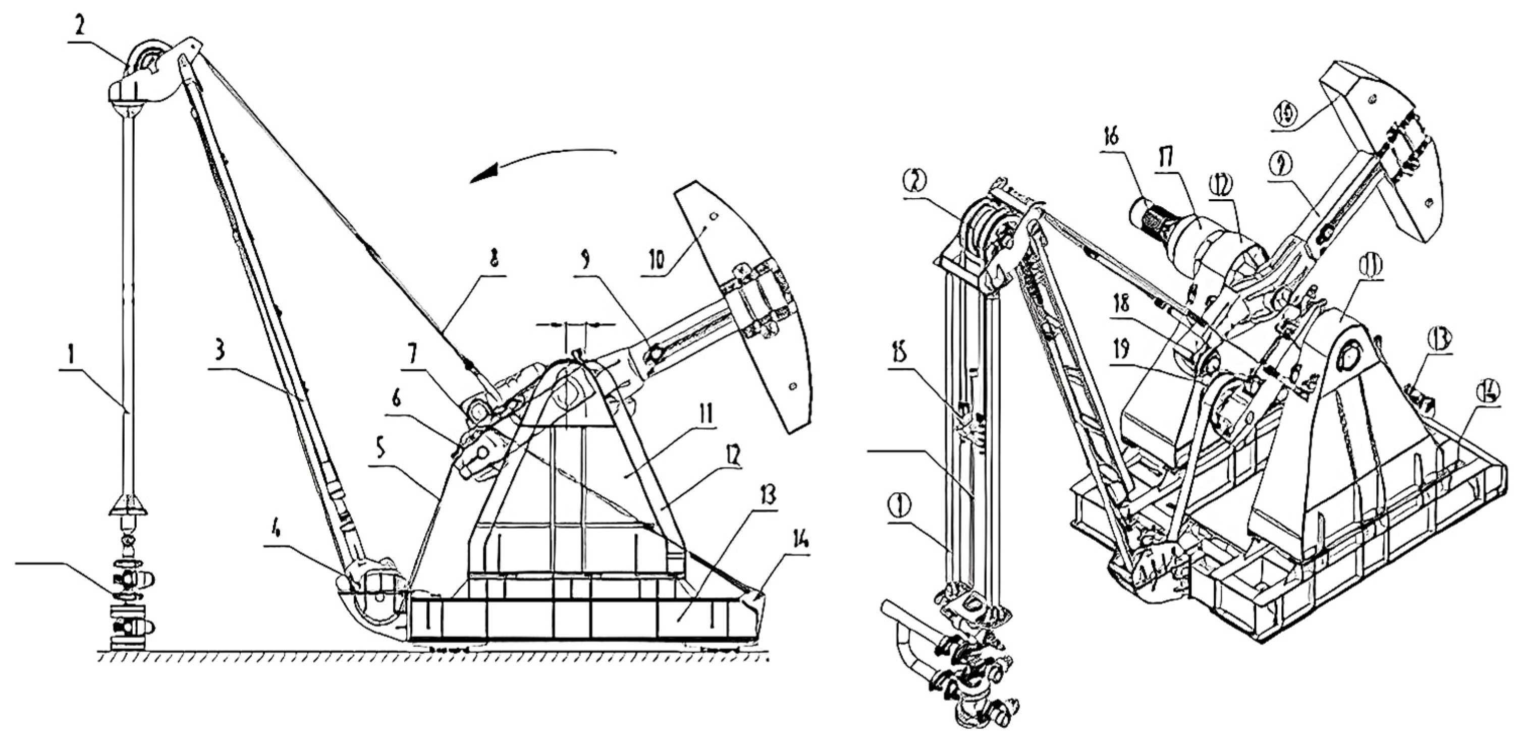
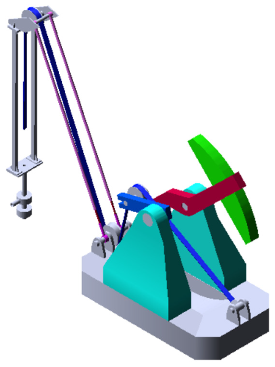
As shown in Figure 1, the eccentric balanced pumping unit is mainly composed of a torque balance system and an energy transfer system. The torque balance system includes a balance device, a crank, a crankshaft and a connecting part; the energy transfer system is composed of motor, direct reducer, brake and so on. The motor and reducer in the power transmission system are connected directly by the shaft, the output crankshaft is connected to the crank, and the crank is connected to the polished rod by the flexible rope on the moving pulley in the torque compensation system. Through the optimization of the flexible transmission structure, the pumping unit is smaller and lighter than the existing pumping units [30,31].
As shown in Figure 1 and Figure 2, the eccentric balance method is relative to the concentric balance. The flexible pumping unit utilizes a double crank connecting rod mechanism and a double rotation center structure. The balance crank 9 drives the counterweight and connects the moving pulley crank 7, which in turn drives the polished rod load. The two cranks rotate counterclockwise around their respective centers O and O′, and there is an eccentricity e between the two rotation centers.
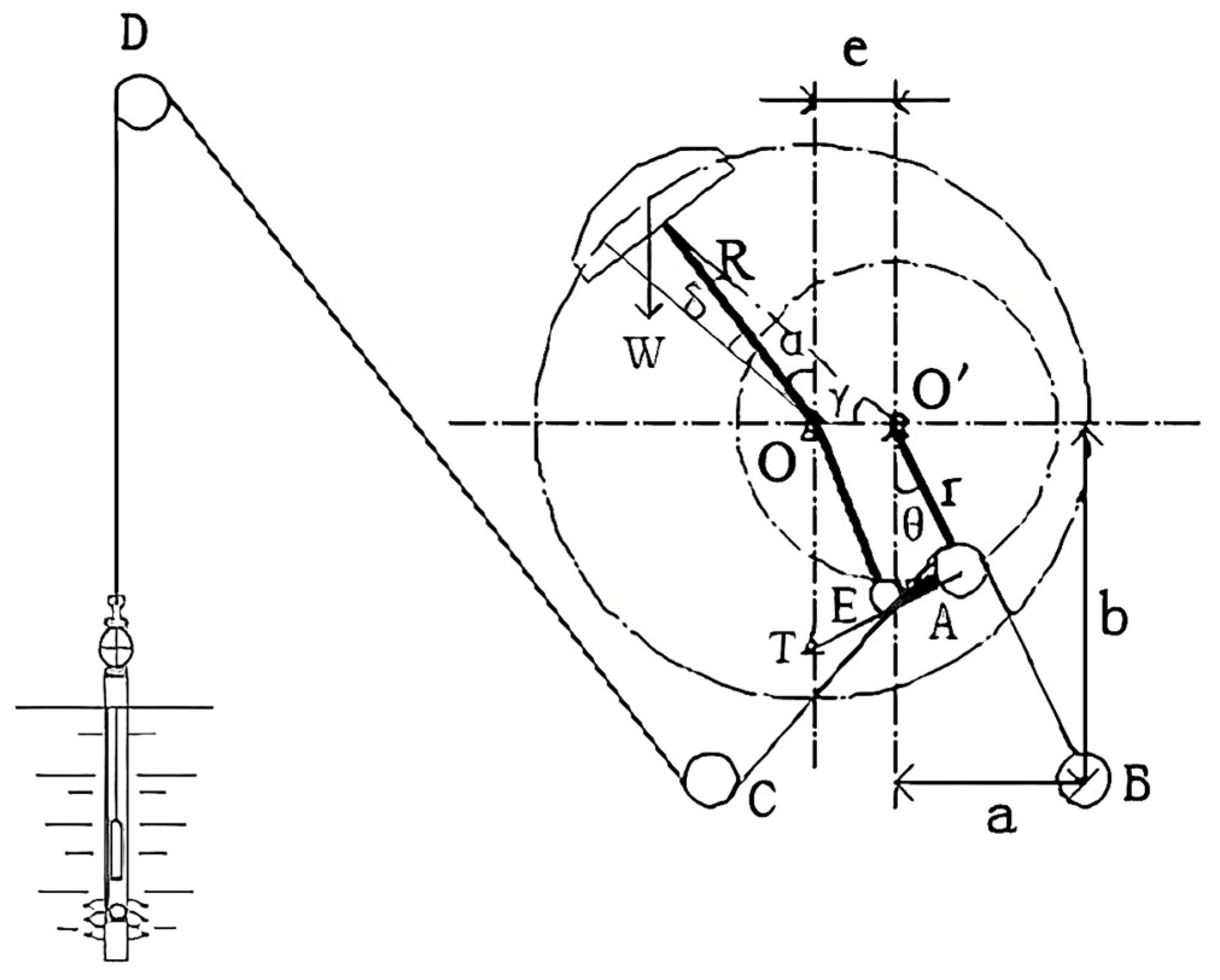
The eccentric balance pumping unit operates on a principle similar to that of the flexible double-stroke pumping unit. Power is transmitted from the fixed node B to the pump via a flexible rope, passing through the moving pulley A, and the fixed pulleys C and D. The four-link mechanism of the pumping unit has been improved, resulting in simplified transmission links and reduced energy loss. Under the same stroke conditions, the eccentric balance pumping unit is smaller and consumes less material than conventional beam pumping units. In addition, the walking mechanism of the beam pumping units is canceled, which reduces the weight of the pumping unit, thus improving the working performance of the pumping unit and reducing the energy consumption.
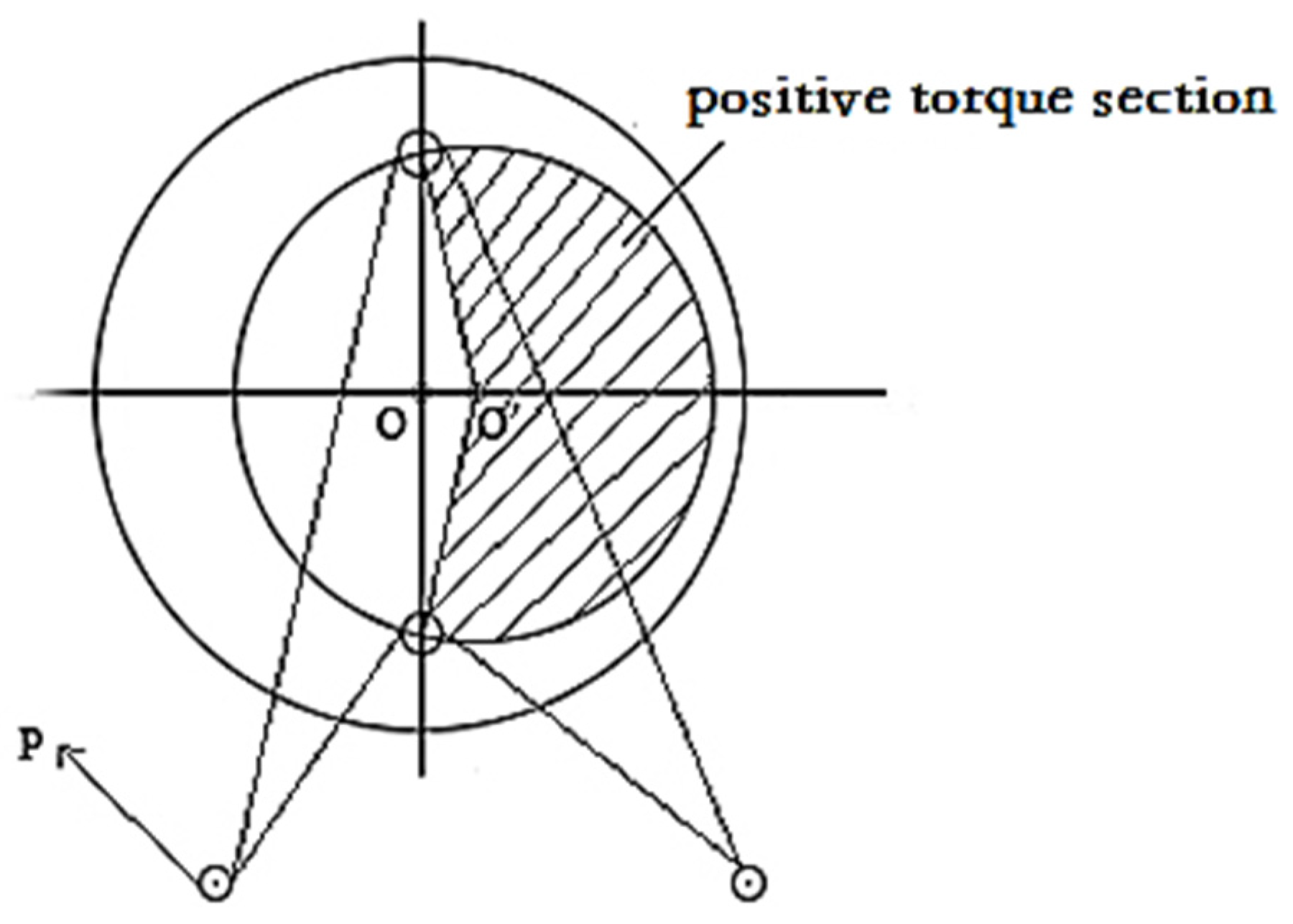
As shown in Figure 2 and Figure 3, the eccentric balancing device adopts a double rotation center mechanism and there is an eccentricity e between the balance crank rotation center O and the moving pulley crank rotation center O′, which changes the working range of the polished rod load, so that the upstroke range of the polished rod load becomes larger and the downstroke interval becomes smaller. This changes the net torque value obtained by superimposing the polished rod load torque and counterweight torque from negative to positive, reducing the peak value and achieving the desired effect of positive torque and uniform variation throughout the cycle.
3. Kinematic and Dynamic Theoretical Calculation of Eccentric Balance Positive Torque Pumping Unit
3.1. Kinetic Analysis
As shown in Figure 1, the crank radius O′A of the moving pulley is r, the rotation center O′ of the moving pulley is located in the middle of the fixed pulley B and C, the horizontal distance between O′ and B is a, the vertical distance is b, the balance crank radius is R, the crank angle of the moving pulley at any time is θ, and the corresponding balance crank angle is α. In order to simplify the calculation, ignoring the radius of the moving pulley, from the geometric relationship [32,33,34,35,36,37,38,39], the following is obtained:
Therefore, the suspension displacement (S) at any time is
The velocity and acceleration of the suspension point can be obtained by taking the first and second derivatives of Formula (3) separately:
3.2. Dynamic Analysis
The force analysis of the movable pulley of the eccentric balanced pumping unit is presented in Figure 4.
The force on the movable pulley is synthesized by assuming that the tension of the flexible rope on both sides of the movable pulley is equal, while ignoring the influence of changes in the rotation speed on the tension of the rope.
where P is the tension of the flexible rope; it is the load of the suspension point. α1 and α2 are, respectively, the angles between the flexible rope and the horizontal direction.
Figure 5 displays the motion and force diagram of the eccentric balance pumping unit. For the triangle O2O3O4,
From the cosine theorem, we can obtain the following:
In the triangle O5O3O4, these formulas below can be derived from the cosine theorem:
According to the geometric relation in Figure 3, it can be concluded that
where θ1 is the crank angle of the counterweight; θ2 is the crank angle of the movable pulley.
3.3. Calculation of Crank Shaft Torque
The force exerted on the crank during the working process of the pumping unit is shown in Figure 5. The torque M of the reducer output shaft O2 is the difference between the polished rod load torque Mo and the counterweight torque Mw [40,41], that is,
As can be seen from the figure,
According to the geometric relationship in the figure and the force balance at point O5, the following equation can be obtained:
The torque of the counterweight acting on the output shaft O2 can be calculated as follows:
where G2 is the weight of the counterbalance, N; L is the length of the balance crank, m; γ is the offset angle, °.
3.4. Calculation Examples
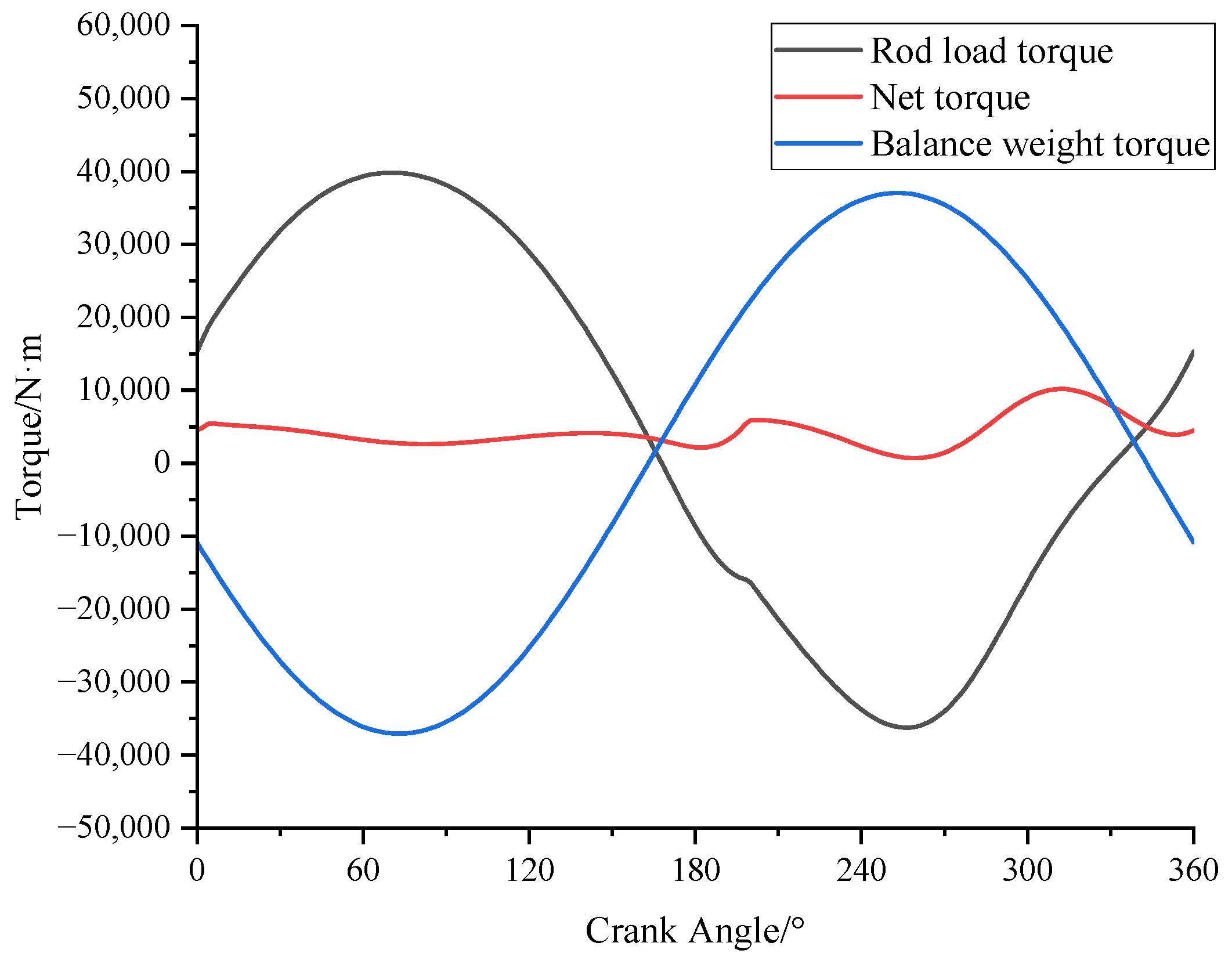
The oil well employs an eccentric flexible pumping unit with the following parameters: pumping speed 4 min−1, crank radius 1 m, downhole pump depth 1000 m, submergence zero, pump diameter 44 mm, sucker rod diameter 22 mm, linear density 3.07 kg/m, liquid density 872 kg/m3, elastic modulus 2.1 GPa. Figure 6 shows the torque curves of the pumping unit through a calculation.
From Figure 6, it is evident that the range of positive and negative torque generated by the polished rod load changes due to the eccentric value between the rotary center of the movable pulley and the rotary center of the balance crank. After being balanced by the counterweight, the maximum torque is only 10,187 N∙m, the minimum torque load increases to 712 N/m from the negative value of the beam pumping units, and the torque load is homogenized and positive. The performance of the pumping unit transmission and the utilization rate of the motor are increased, while the installed power and energy loss are reduced, resulting in an overall improvement in system efficiency.
4. Simulation Pre-Processing
Taking into account the quality parameters of each component of the eccentric balanced pumping unit and the influence of the structural parameters on the dynamic performance of the pumping unit, the three-dimensional solid model of the eccentric balanced positive torque pumping unit was established using SolidWorks software version 2020 and imported into ADAMS software version 2020 for the kinematic and dynamic analysis of the pumping unit.
4.1. Modeling
The three-dimensional solid model of the eccentric balanced positive torque pumping unit was established in SolidWorks software and imported into ADAMS software, as shown in Figure 7.
4.2. Editing Part Attributes
The properties of each part in ADAMS was edited, which mainly included setting the part name and mass. Due to the large number of parts in this model, setting the part name was convenient for the identification of each part in the post-processing analysis of the model. Each part was a homogeneous material, and the main part qualities that affect the dynamic performance of the pumping unit are listed in Table 1.
4.3. Applying Polished Rod Load
The polished rod load was applied at the end of the rope. And the direction of the force was perpendicular to the traveling beam, downward, and the force moved with the body, so that the polished rod load was fixed at the end of the rope and moved with the movement of the rope. The polished rod load function was written using a STEP function as follows:
STEP (time, 0, 12,000, 1.5, 25,000) + STEP (time, 1, 0, 5.3, −3000) + STEP (time, 5.3, 0, 6.3, −12,000)
+ STEP (time, 6.3, 0, 10, 2000)
+ STEP (time, 6.3, 0, 10, 2000)
The variation in the polished rod load as a function of displacement is shown in Figure 8.
5. Analysis of Simulation Results
The simulation period was set to 10 s, which was the time taken for a 360° rotation of the pumping unit balance crank.
5.1. Kinetic Analysis
5.1.1. Analysis of Displacement, Velocity and Acceleration of Polished Rod
Figure 9 shows that the maximum displacement of the dangling point is 2.31 m, the maximum velocity of the dangling point is −0.84 m/s and the maximum acceleration is −0.574 m/s2, with which the pumping unit exhibited good motion characteristics. The upstroke range of the dangling point motion exceeds 180°, and the lower stroke working interval is less than 180°, which is consistent with the theoretical analysis.
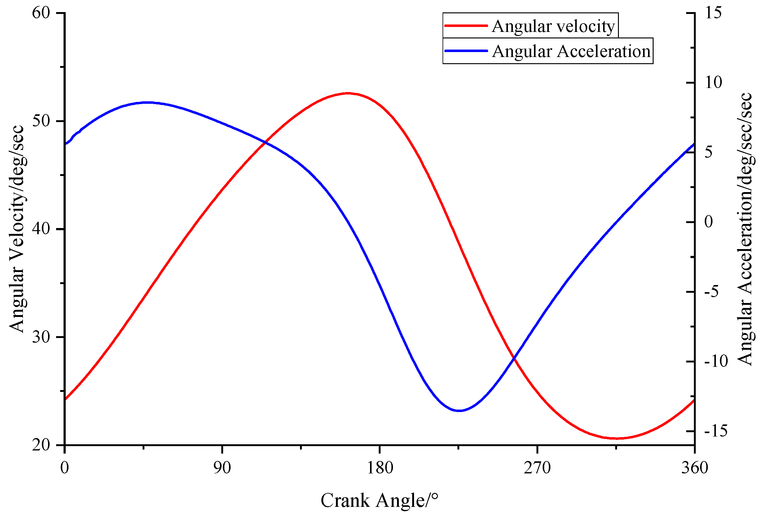
5.1.2. Analysis of Angular Velocity and Angular Acceleration of Moving Pulley Connecting Rod
Figure 10 is a graph showing that the maximum angular velocity of the connecting rod is near the dead point of the upper stroke, and the maximum angular velocity is 52.1°/s. The minimum angular velocity is near the bottom dead point, and the minimum angular velocity is 20.9°/s. The maximum angular acceleration is 8.6°/s2 at one-third of the upper stroke, and the minimum angular acceleration is −13.4°/s2.
5.1.3. Analysis of Angular Velocity and Angular Acceleration of Moving Pulley Handle
As shown in Figure 11, the maximum angular velocity of the dynamic pulley crank is near the dead point of the upper stroke, with a maximum angular velocity of 42.5°/s and a minimum angular velocity of 30.4°/s. The maximum angular acceleration is 5.1°/s2, and the minimum angular acceleration is −2.3°/s2.
5.2. Dynamic Analysis
5.2.1. Analysis of Torque Superposition
As can be seen from Figure 12, the maximum net torque is 12,946 N∙m, and the minimum output net torque is 2775 N∙m. The output net torque of the pumping unit is positive throughout the entire working cycle, and the change is uniform, which is in line with the theoretical calculation results. The eccentric balanced pumping unit could effectively reduce the installed power and improve the working efficiency.
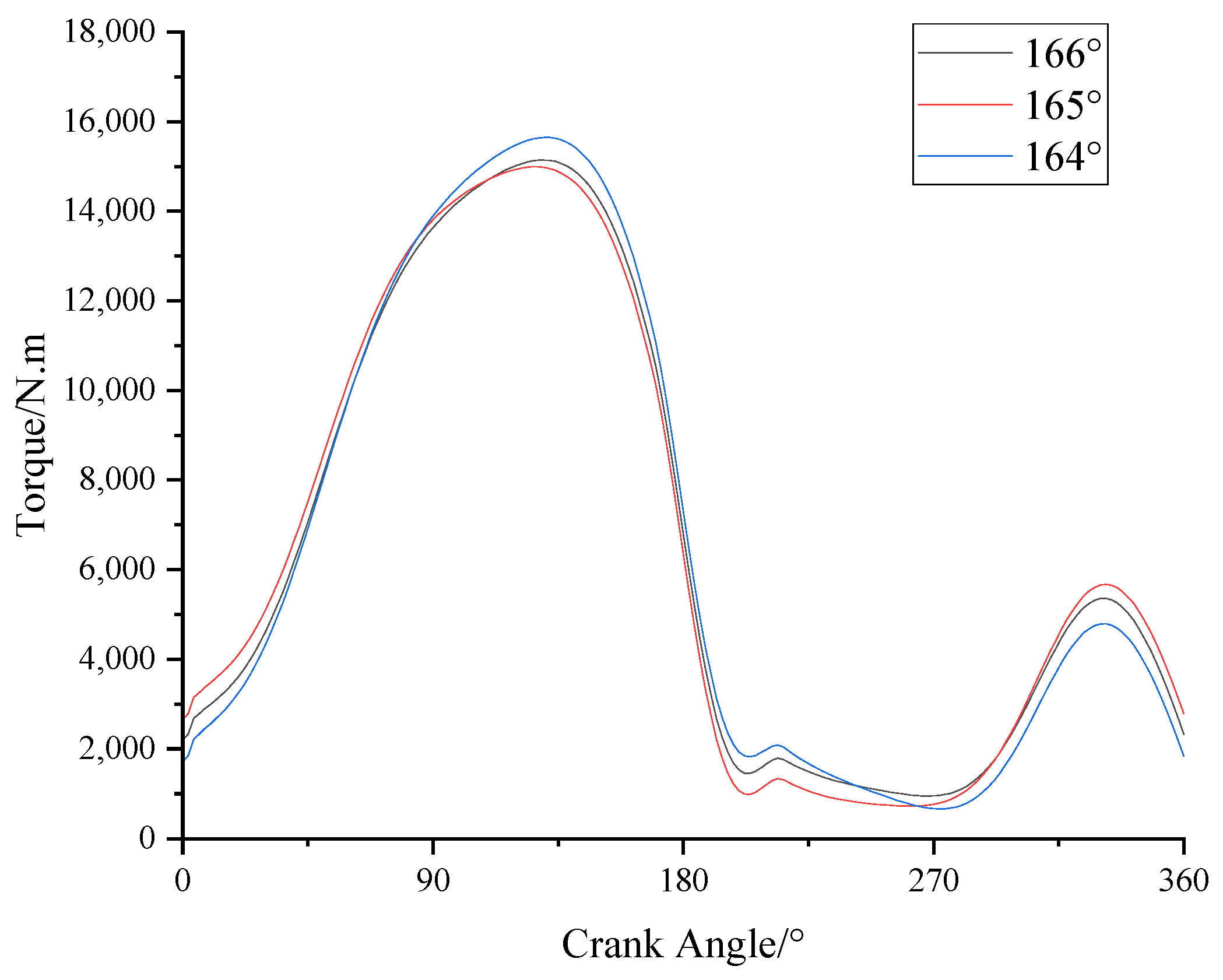
5.2.2. Analysis of Balance Crank Angle λ
Figure 5 shows a particular angle λ between the balance crank of the eccentric balanced pumping unit. Figure 13 presents the net torque curves obtained at various angles. From the figure, it is apparent that the magnitude of the net torque curve decreases and then increases as the angle λ decreases. When λ is at 165°, the amplitude of the curve is the smallest, indicating that the net torque is more equitably distributed throughout the cycle. Therefore, the balance crank angle λ of 165° is chosen for this simulation.
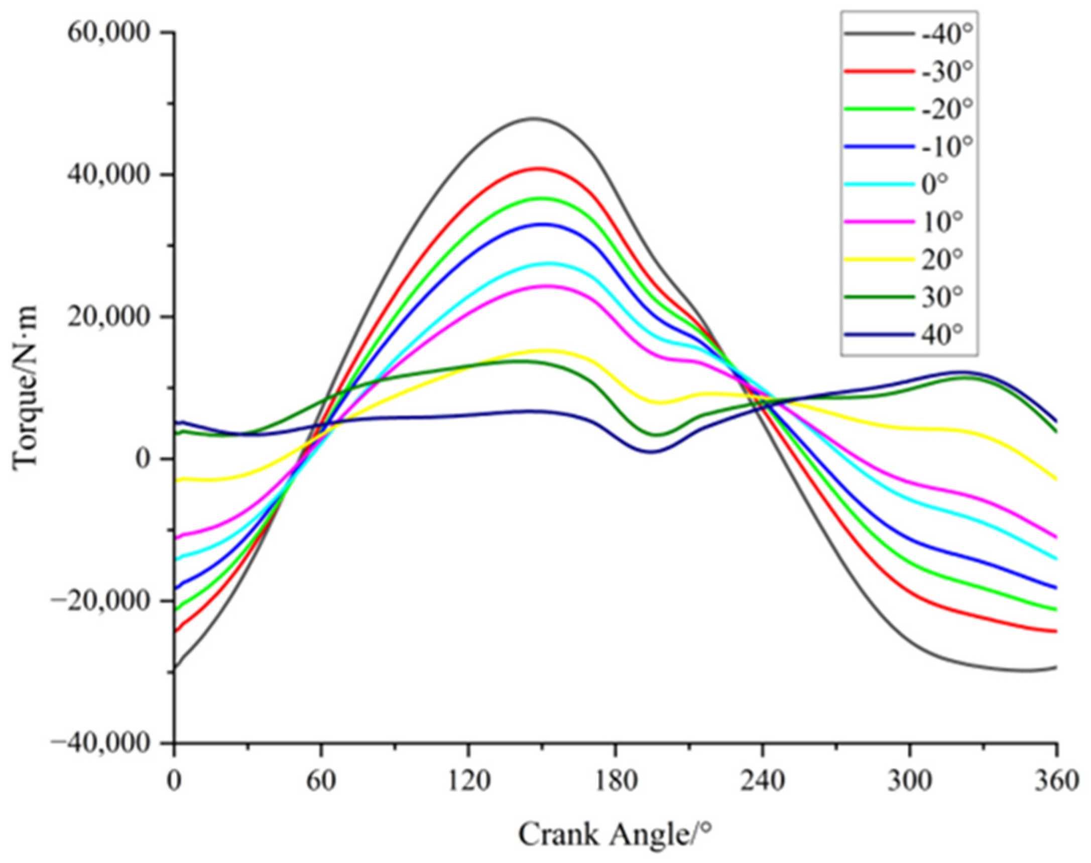
5.2.3. Analysis of Counterweight Center of Mass Offset Angle δ
As shown in Figure 2, there exists a offset angle δ in the counterweight center of mass, which is defined as positive in the clockwise direction and negative in the anti-clockwise direction according to the law of coordinate transformation:
where x, y, z represent the coordinate value of the counterweight center of mass after rotation, m; x1, y1, z1 represent the coordinate value of the rotation center of the counterweight, m; δ represents the offset angle of the counterweight center of mass, °; a represents the radius of the counterweight center of mass, m.
The counterweight center of mass underwent rotations of 10°, 20°, 30° and 40° in the counterclockwise and clockwise directions, and the coordinates of its center of mass were subsequently determined as shown in Table 2.
The mass of the counterweight was set to 1500 kg, and the rotation radius of the counterweight center of mass was set to 1400 mm. Figure 14 shows the net torque curve of the output shaft under different offset angles. The diagram indicates that the amplitude of the curve is significantly influenced by different offset angles. A negative offset angle results in an increased fluctuation range of the torque curve, leading to negative torque on the output shaft. The higher offset angle has a greater amount of existing negative torque. For positive offset angles greater than 30°, the net torque on the gear box is entirely positive. At an offset angle of 30°, the superimposed torque shows the smallest fluctuation range, consistently with positive values. So, 30° is chosen as the offset angle δ in this simulation.
5.2.4. Analysis of the Radius of Counterweight Center of Mass
The distance between the center of mass of the balance crank and the rotation center is the rotation radius of the center of mass of the balance crank. Table 3 shows the coordinates of the center of mass of the balance crank under different rotation radii.
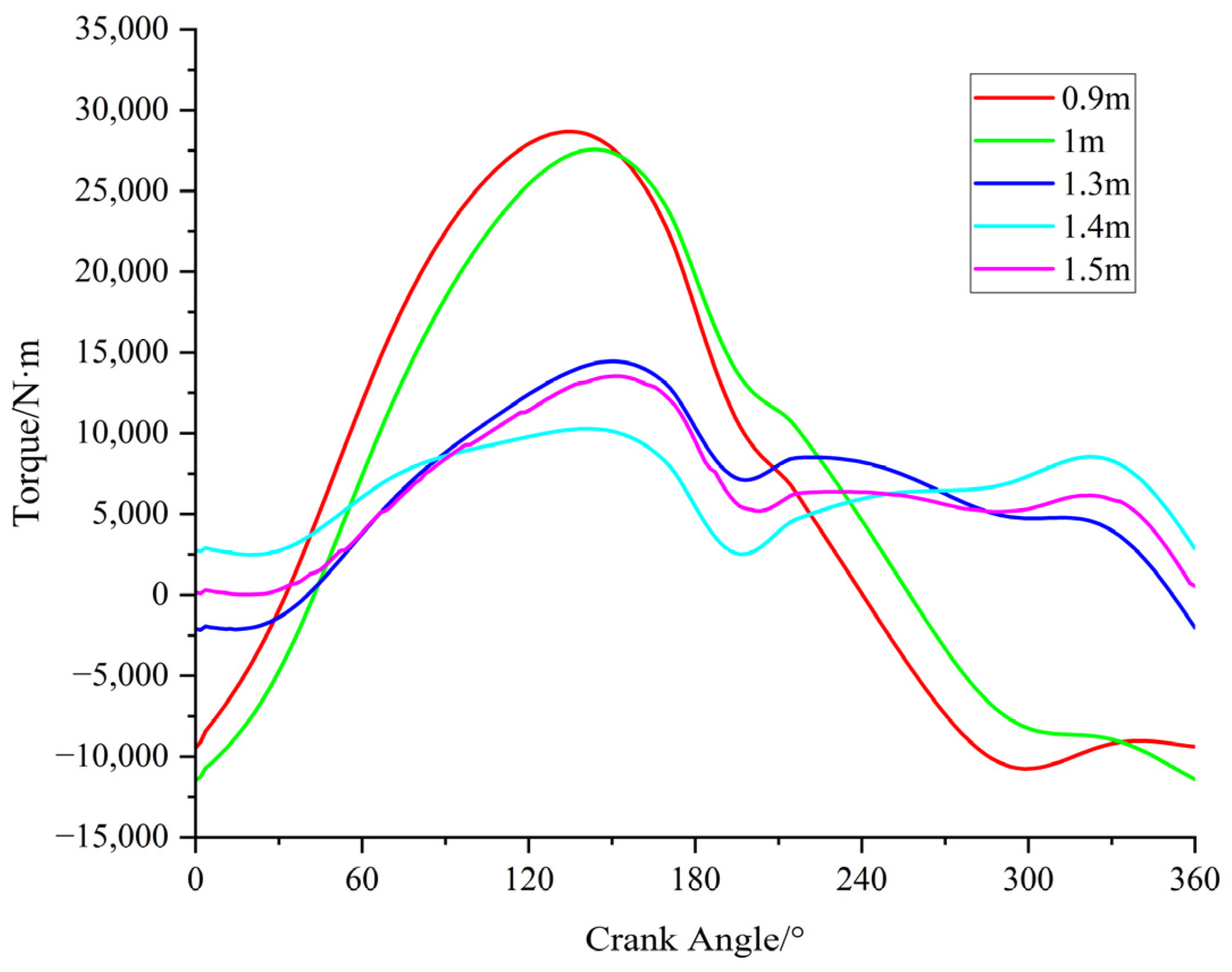
The weight of the balance crank was established as 1500 kg, and the offset angle δ was 30°. The change in the net torque of the output shaft when the distance between the center of mass of the balance crank and the center of rotation is varied is illustrated in Figure 15. From the diagram, it is apparent that alterations to the rotation radius have a more pronounced effect on the shape of the curve fluctuations rather than solely impacting the torque curve amplitude. Additionally, changes in the radius of the center of mass affect the phase of the curve. When the radius of the center of mass increases, the curve amplitude is markedly decreased, and the absolute value of the curvature of all the curve sections is diminished. When the rotation radius is 1.4 m, no negative torque is observed, and the fluctuation amplitude is at a minimum during the working cycle of the pumping unit. Consequently, the torque can be adjusted by varying the rotation radius at the crank center of mass when deciding the mass and deflection angle of the balance crank. In this particular simulation, a rotation radius of 1.4 m was chosen as the center of mass radius for the balance crank.
5.2.5. Analysis of Crank Length of Moving Pulley and Connecting Rod of Moving Pulley
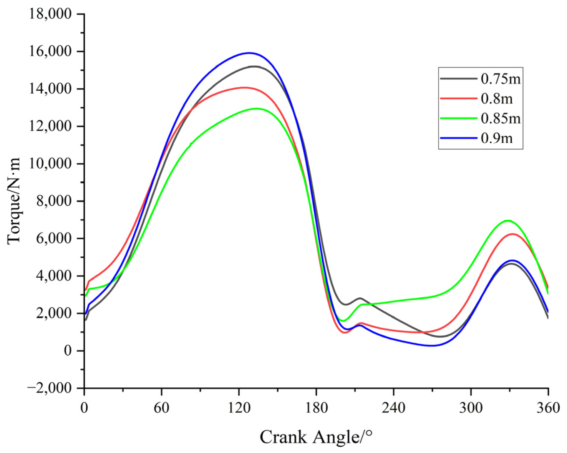
The motion diagram in Figure 2 shows that the rotation center ‘O’A’ for the moving pulley can be altered by changing the length of the crank. Figure 16 presents the net torque curve of the output shaft for varying the radial displacement of the moving pulley.
Figure 16 shows that increasing the rotating radius of the moving pulley results in an increase in the minimum net torque on the gear box and a reduction in the fluctuation range of the curve. The maximum net output torque is reached when the rotating radius increases to 0.85 m. Further increasing the rotating radius leads to a decrease in the minimum net output torque and an increase in the fluctuation range of the torque curve. It can be observed from the figure that the simulation used a rotational radius of 0.85 m for the moving pulley.
Figure 17 shows the net torque curve on the gear box with respect to the changing length of the moving pulley connecting rod, also known as the AE in the motion diagram of the eccentric balanced pumping unit, as depicted in Figure 2. As observed from the figure, increasing the length of the connecting rod resulted in an initial decrease and then an increase in the amplitude of the torque curve, and the minimum net output torque on the gear box first increased and then decreased. At a length of 300 mm for the moving pulley connecting rod AE, the minimum net output torque on the gear box reached its maximum, and the torque curve exhibited the least fluctuation. As indicated in the diagram, the length of the connecting rod of the moving pulley was chosen as 300 mm.
5.2.6. Optimal Parameters of Eccentric Balanced Pumping Unit Model
After the dynamic simulation analysis of the key components of the eccentric flexible pumping unit, the optimal parameter values of each key component were obtained, as shown in Table 4.
6. Indoor Test and Field Application
After analyzing the kinematics and dynamics of the eccentric balanced pumping unit, it is evident that the pumping unit displays an exceptional dynamic performance and produces significant energy savings. To verify the correctness and reliability of the model, indoor test and field test data will need to be obtained, in accordance with the research and development principle of combining theory and practice. Therefore, the calibration of the eccentrically balanced pumping unit is achieved through indoor testing and field applications.
6.1. Indoor Test
A performance test was conducted to determine if the various performance indexes of the eccentric balanced pumping unit could fulfill the pertinent industry standards and design requirements, and this test adopted the well testing simulation testing method. The test contents mainly included the following:
- (1)
- By changing the radius of rotation of the movable pulley and related devices, whether the change in the stroke and pumping speed of the pumping unit achieves the expected goal is verified, and the basic structural parameters and the degree of simplicity of operation are tested.
- (2)
- The stiffness of the pump unit is tested by varying parameters such as the polished rod load, stroke and pumping speed to verify that parameters such as the vibration, noise and maximum allowable load of the pump unit meet the design objectives.
- (3)
- By detecting the change rule of the pumping machine power and current and other parameters under different working conditions, the electrical parameters are tested to verify the correctness of the principle of eccentric balance.
- (4)
- Wear testing is conducted on the pumping unit mainly for noise and reducer oil temperature.
Through the above tests, the rationality of the design of the eccentric flexible pumping unit and the reliability of the product were determined.
6.1.1. Laboratory Equipment
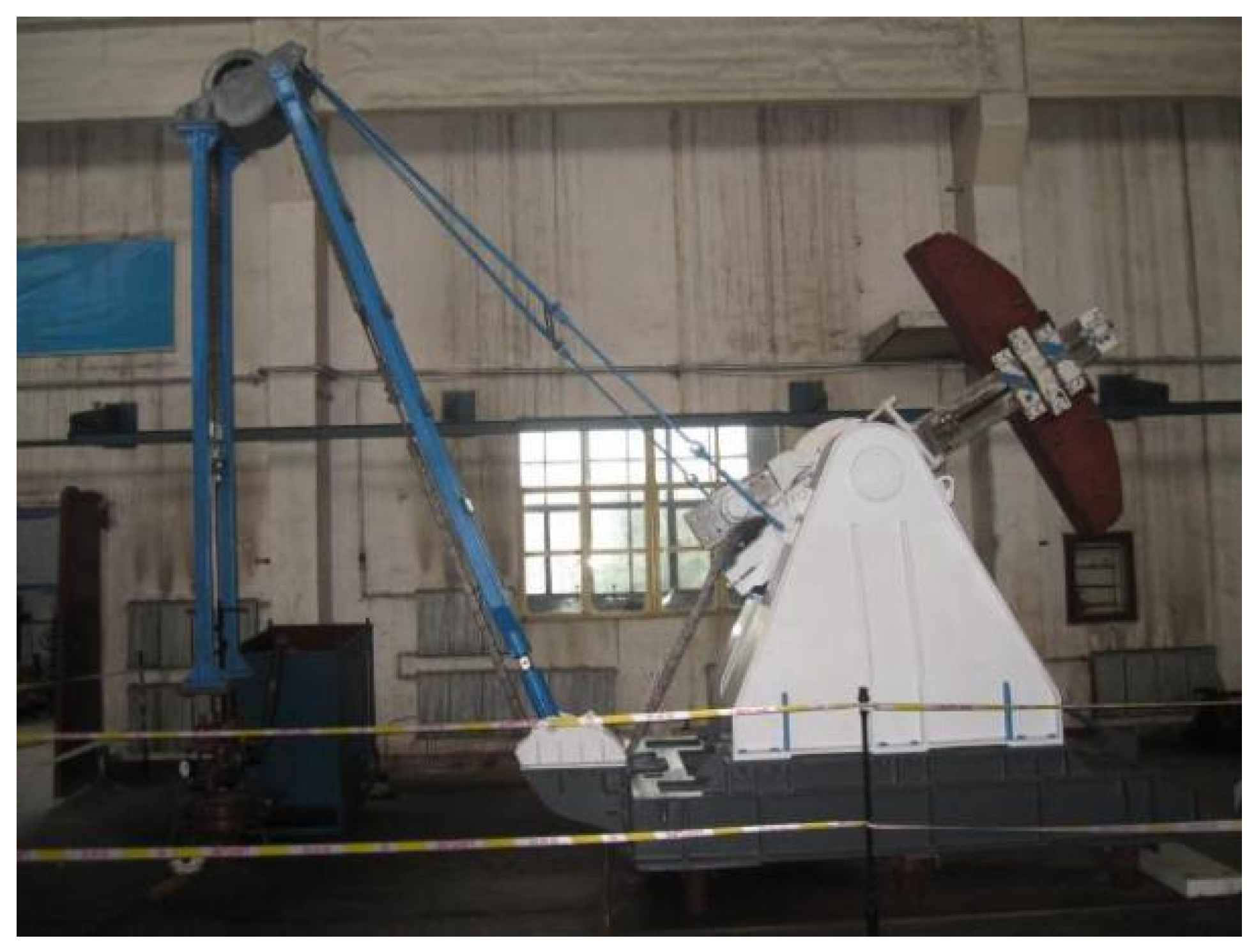
The following equipment was mainly used in the test: an eccentric balanced pumping unit, a test well with a depth of 70 m, a pumping rod, a hydraulic feedback self-sealing plunger with a pump diameter of φ70 mm, an oil storage tank, a wellhead pressure-holding device, a frequency converter, a flowmeter, a sound level meter, an infrared thermometer, a latitude and longitude meter and a clamp-on ammeter. An image of the pumping unit indoor test is shown in Figure 18.
6.1.2. Analysis of Stability Test Results
The stability test parameters and results of the pumping unit are listed in Table 5. During the production process, the other components of the pumping unit, including the load-bearing and connecting parts, underwent testing and met standard requirements with no instance of flexible transmission parts slipping or loosening during operation. The disclosed test results confirm that the design standards are met with regard to the basic parameters and performance of the eccentric balanced pumping unit. Furthermore, the smoothness of the whole machine, the reliability and sealing of the components and the reliability of the braking mechanism also met the relevant industry design requirements.
6.1.3. Analysis of Electrical Parameter Test Results
The electric parameter test of the eccentric flexible pumping unit was carried out indoors to verify the principle of the eccentric design and the power-saving effects. The rated power of the motor was 3 kW, the matched hydraulic feedback self-sealing piston pump with pump diameter φ70 mm was used, the experimental medium was 10# diesel oil, the electric current and power parameter were read using the clamp ammeter and the inverter control panel, and several sets of experimental data were obtained, as shown in Table 6, by changing the balancing parameter and the wellhead pressure.
According to the working characteristics of the rod pumping system, with the light rod suspender as the boundary, the system efficiency can be divided into two parts, surface efficiency and downhole efficiency [42], which can be expressed as
where ηlift is lifting efficiency; ηmech is the mechanical efficiency; Phydr is the hydraulic power used for fluid lifting, kw; PRHP is the PRHP at the surface, kw; Pmot is the mechanical power required at the motor shaft, kw.
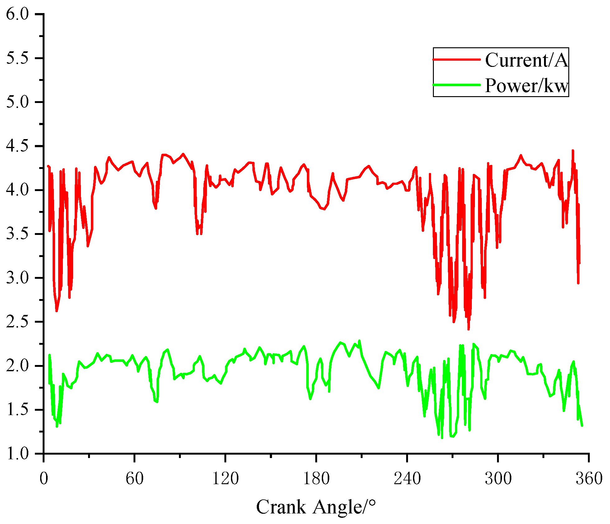
Taking one set of data as an example, the measured motor current and power are shown in Figure 19.
Figure 19 illustrates that while there is a slight fluctuation in the current and the dead center position of the up and down strokes, the remaining positions remain stable, exhibiting a significant balancing effect. The motor power remains constant at approximately 2 kW and the efficiency of the eccentric balance pumping machine system was measured at 37.8% during the test.
The results of the indoor test indicate that the design principle of the eccentric balance pumping machine is correct and technically viable. The basic parameters and working performance of the prototype satisfy the design necessities, including an easily adjustable stroke, balance, eccentric distance, and other factors with performance indexes meeting relevant industry standards.
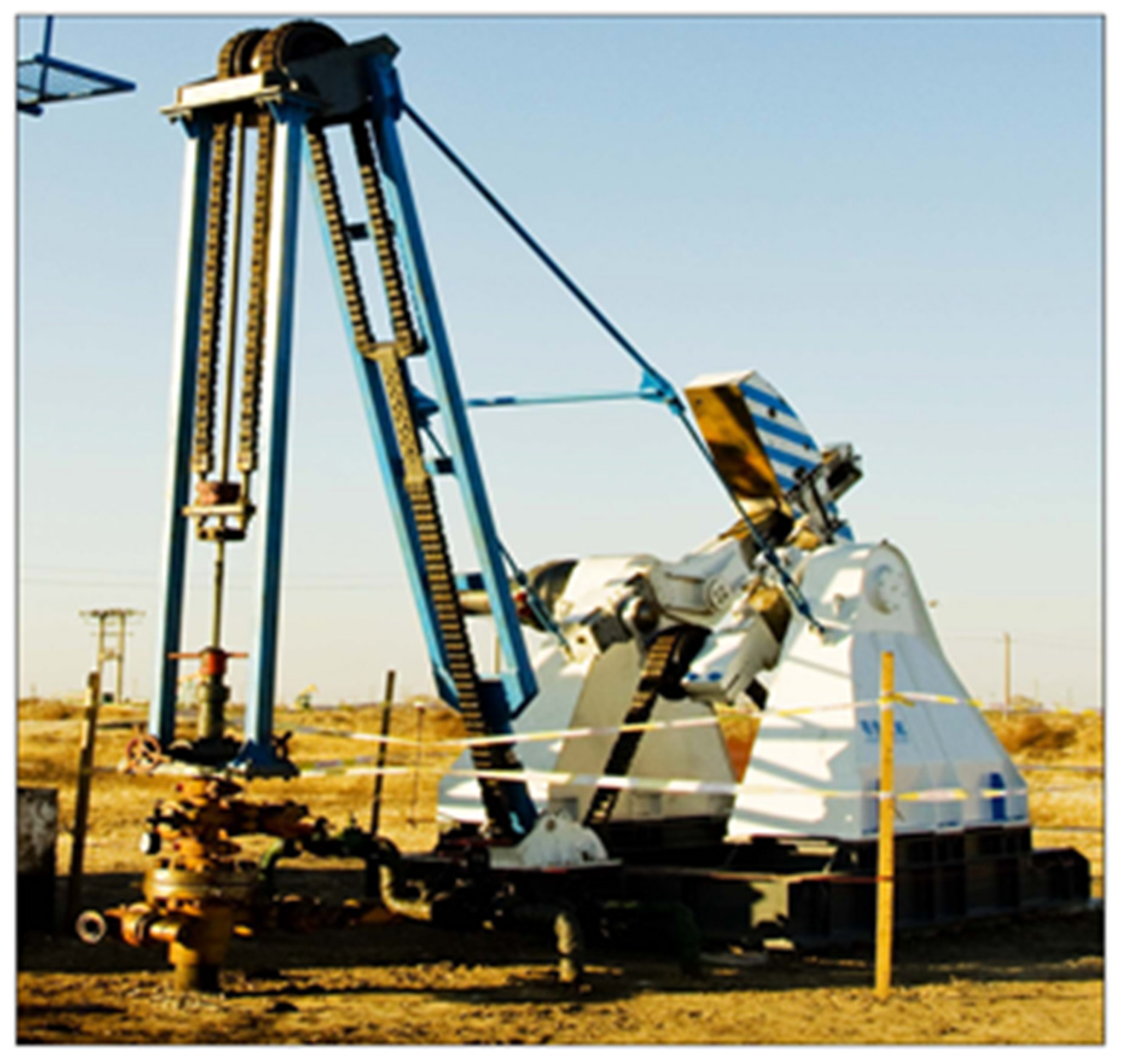
6.2. Field Application
In order to assess the power-saving capabilities and ensure the operational safety and reliability of the eccentric balance pumping unit under field working conditions, the pumping unit was deployed in the field. The parameters of the producing well are shown in Table 7.
Field application of the pumping unit in a production well as shown in Figure 20.
The experimental data for the eccentric pumping unit and beam pumping unit are shown in Table 8.
Based on the data provided in Table 8, it can be inferred that the eccentricity balance pumping unit possesses an installed power which is 80% less than that of the beam pumping unit, resulting in a weight reduction of 25%. Furthermore, the gear box has the ability to generate positive torque throughout the complete cycle, resulting in a notable balancing effect, and the system efficiency increases from 14% of the beam pumping unit to 24.3%; the power savings rate exceeded 50%.
7. Conclusions
Comparing the calculated results with the experimental results, it can be seen that the torque on the output shaft of the reducer is positive. And based on the experimental results, the following conclusions can be made:
- (1)
- The eccentric balanced positive torque pumping unit was designed to use a flexible energy transfer system instead of a rigid structure, which can greatly reduce the energy transfer links and energy loss. In addition, the eccentric rotating mechanism was used to change the work range of the polished rod load. This caused the upstroke interval to increase and the downstroke interval to decrease. So, the net torque fluctuation was reduced and the net torque was positive when the counterweight torque was supplemented with the polished rod load torque.
- (2)
- The kinematic and dynamic analysis model of the eccentric balanced pumping unit was established, and theoretical calculations and analyses of the kinematics and dynamics were carried out, and these proved that the pumping unit achieves full-cycle positive torque operation. In addition, the ratio of the maximum torque to minimum torque was 14.3, which reduced the torque fluctuation range.
- (3)
- The simulation analysis of the eccentric balanced pumping unit with ADAMS verifies that, in the theoretical analysis, the pumping unit can achieve positive torque work. In addition, the key parameters of the pumping unit affecting the balancing effect such as the balance crank angle λ and the counterweight center of mass offset angle δ were optimized, so it was determined that the optimal selection of the angle λ was 165°, and the optimal selection of the offset angle δ was 30°.
- (4)
- After the indoor testing and field application of the eccentric balanced positive torque pump unit, it is obvious that the design principle of the pumping unit is feasible, the working performance of the pumping unit is reliable, the installed power is reduced by 80%, the weight of the entire prototype is decreased 25%, the working efficiency can reach up to 24.3% and the electricity savings reached more than 50%. So, the pumping unit can effectively improve system efficiency and oil production efficiency.
Author Contributions
Conceptualization, J.X.; methodology, J.X. and H.L.; software, W.W.; validation, J.X., W.W. and H.L.; formal analysis, J.X. and W.W.; investigation, J.X. and Q.Z.; resources, J.X.; data curation, J.X.; writing—original draft preparation, J.X.; writing—review and editing, J.X. and W.W.; visualization, J.X.; supervision, W.L.; project administration, J.X.; funding acquisition, W.L. All authors have read and agreed to the published version of the manuscript.
Funding
This research was funded by the Intelligent Manufacturing of High-end Petroleum and Petrochemical Equipment, School of Mechanical Science and Engineering, Northeast Petroleum University (No. 15141220501) and the Natural Science Foundation of China (No. 52274005).
Data Availability Statement
The data used in this study are available from the corresponding author on reasonable request.
Acknowledgments
The authors would like to thank the editors and anonymous reviewers for their valuable comments and suggestions.
Conflicts of Interest
The authors declare no conflict of interest.
References
- Badoiu, D.; Toma, G. Research concerning the identification of some parameters of a sucker rod pumping unit. Rev. Chim. 2017, 68, 2289–2292. [Google Scholar] [CrossRef]
- Bhatkar, S.; Anwar, S.O. Optimizing crude oil production in Sucker Rod Pumping wells using QRod Simulator. Adv. Eng. Appl. Sci. Int. J. 2013, 3, 1–4. [Google Scholar]
- Takacs, G. Sucker-Rod Pumping Handbook: Production Engineering Fundamentals and Long-Stroke Rod Pumping; Gulf Professional Publishing: Houston, TX, USA, 2015. [Google Scholar]
- Toma, G. Research concerning the optimization of the mechanism of the conventional sucker rod pumping units. Rev. Chim. 2019, 70, 1795–1799. [Google Scholar] [CrossRef]
- Enikeeva, E.R.; Alaeva, N.N. Analysis of Operation and Ways to Improve the Efficiency of the Pumping Unit. In Proceedings of the 2023 International Conference on Industrial Engineering, Applications and Manufacturing (ICIEAM), Sochi, Russia, 15–19 May 2023; IEEE: New York, NY, USA, 2023; pp. 1–5. [Google Scholar]
- Xing, M.; Dong, S. A new simulation model for a beam-pumping system applied in energy saving and resource-consumption reduction. SPE Prod. Oper. 2015, 30, 130–140. [Google Scholar] [CrossRef]
- Liu, J.; Zhu, J. Design research on working mechanism of beam pumping unit. Appl. Mech. Mater. 2010, 37, 340–343. [Google Scholar] [CrossRef]
- Yan, W.; Yin, S.; Du, J. The Development Process of Pumping Unit and Innovation of Pumping Mode. Mech. Eng. 2007, 3, 111–112. [Google Scholar] [CrossRef]
- Feng, Z.; Guo, C.; Zhang, D.; Cui, W.; Tan, C.; Xu, X.; Zhang, Y. Variable speed drive optimization model and analysis of comprehensive performance of beam pumping unit. J. Pet. Sci. Eng. 2020, 191, 107155. [Google Scholar] [CrossRef]
- Ye, Z.; Liu, Z.; Cheng, C.; Tan, L.; Feng, K. Efficient evaluation model of beam pumping unit based on principal component regression analysis. Sci. Prog. 2020, 103, 0036850419895769. [Google Scholar] [CrossRef] [PubMed]
- Busarov, S.S.; Busarov, I.S.; Titov, D.S. Studies of the Effect of Leaks of the Working Chamber on the Working Process of Long-Stroke Ultra-Low-Speed Piston Compressor and Pump Units. Chem. Pet. Eng. 2019, 55, 480–485. [Google Scholar] [CrossRef]
- Cai, W.; Li, W. Finite element analysis and application of a chain pumping unit frame. Chem. Technol. Fuels Oils 2022, 58, 200–208. [Google Scholar] [CrossRef]
- Ren, T. Scheme design and performance analysis of a new chain drive pumping unit. Xi’an Univ. Pet. (Nat. Sci.) 2009, 24, 72–74. [Google Scholar]
- Shao, J.; Ding, K.; Wang, D. Kinematics Analysis of Incomplete Gear and Rack Pumping Unit. J. Phys. Conf. Ser. 2021, 2095, 012090. [Google Scholar] [CrossRef]
- Mourlevat, J. Long-stroke pump boosts heavy oil recovery. World Oil (United States) 1982, 195, 83–87. [Google Scholar]
- Kennedy, D.M.; Ghareeb, M. Ultra-long stroke and intelligent rod pumping system for producing difficult wells and/or fluids. In Proceedings of the SPE Asia Pacific Oil and Gas Conference and Exhibition, Jakarta, Indonesia, 17–19 October 2017; SPE: Kuala Lumpur, Malaysia, 2017; p. D011S003R003. [Google Scholar]
- Liu, Y.; Wu, L.; Wei, Y.; Dong, C. Study on Test of Characteristics of a New Drum Pumping Unit. J. Southwest Pet. Univ. (Nat. Sci. Ed.) 2022, 44, 174–180. [Google Scholar]
- Feng, G. Belt-driven oil pumping machine. Pet. Mach. 1986, 7, 24. [Google Scholar]
- Tse, R.; Wu, L. Research on the Technology of Elasticity Tension Device for Belt Drive Used in Pumping Unit of Oil Field. Mech. Transm. 2013, 37, 72–74. [Google Scholar] [CrossRef]
- Tan, C.; Tan, P.; Li, X.; Wu, H.; Yang, R. Research on flexible variable-speed control model and optimization method of rod pumping well based on genetic algorithm. In Proceedings of the 2017 International Conference on Applied System Innovation (ICASI), Sapporo, Japan, 13–17 May 2017; IEEE: New York, NY, USA, 2017; pp. 1771–1774. [Google Scholar]
- Li, J.; Yang, H.Z.; Han, M.; Xu, J.C.; Li, X.D.; Han, X.T.; Cheng, Y.F. Study on single crank flexible pumping unit in oil field artificial lift. Appl. Mech. Mater. 2011, 66, 471–476. [Google Scholar] [CrossRef]
- Sapietová, A.; Sekerka, M.; Vaško, M.; Sapieta, M. Synthesis of a pumping unit with consideration of a flexible member in the system. Advances in Science and Technology. Res. J. 2016, 10, 119–123. [Google Scholar]
- Xu, C.; Wang, Y.; Wu, Y.; Zhang, S. Research on Flexible Control Technology of Pumping Unit. In Proceedings of the 2022 IEEE International Conference on Mechatronics and Automation (ICMA), Guilin, China, 7–10 August 2022; IEEE: New York, NY, USA, 2022; pp. 208–213. [Google Scholar]
- Fu, H.; Zou, L.; Wang, Y.; Feng, Z.; Song, Z. Study on design and simulation analysis of the double horse-head pumping unit based on the compound balance structure. Proc. Inst. Mech. Eng. Part C J. Mech. Eng. Sci. 2015, 229, 3034–3046. [Google Scholar] [CrossRef]
- Sun, W.; Li, C.; Tao, Q.; Tan, Y. The design and simulation of beam pumping unit. In Proceedings of the 2015 21st International Conference on Automation and Computing (ICAC), Glasgow, UK, 11–12 September 2015; IEEE: New York, NY, USA, 2015; pp. 1–4. [Google Scholar]
- Yang, X. Analysis of horsehead strength calibration of double donkey head pumping machine. Shandong Ind. Technol. 2018, 7, 89+137. [Google Scholar] [CrossRef]
- Zhang, C.; Wang, L.; Li, H.; Wang, L. Experimental research on parameters of a late-model hydraulic-electromotor hybrid pumping unit. Math. Probl. Eng. 2020, 2020, 2923154. [Google Scholar] [CrossRef]
- Qu, W.T.; Liao, D.S.; Ren, T.; Sun, W. Optimum design of double-well pumping units based on calculation of MATLAB optimization toolboxes. Adv. Mater. Res. 2012, 479, 694–698. [Google Scholar] [CrossRef]
- Zhou, Q.Y.; Zheng, Z.J.; Ji, L.; Yan, Y. Frame mechanics analysis of tower long-stroke pumping unit. West. Explor. Eng. 2011, 23, 51–54. [Google Scholar]
- Xu, J.; Li, W.; Meng, S. Kinematic and Dynamic Simulation Analysis of Modified Conventional Beam Pumping Unit. Energies 2022, 15, 5496. [Google Scholar] [CrossRef]
- Xu, J.; Meng, S. Design and application of eccentric balance flexible pumping unit. IOP Conf. Ser. Earth Environ. Sci. 2019, 267, 032033. [Google Scholar]
- Aditsania, A.; Rahmawati, S.D.; Sukarno, P.; Soewono, E. Modeling and simulation performance of sucker rod beam pump. AIP Conf. Proc. 2015, 1677, 080008. [Google Scholar]
- Ahmedov, B. Assessment of dynamic efforts taking into account of inertial and vibrating loads in deaxial pumping units. J. Pet. Explor. Prod. Technol. 2020, 10, 1401–1409. [Google Scholar] [CrossRef]
- Aliev, F.A.; Dzhamalbekov, M.A.; Veliev, N.A.; Gasanov, I.R.; Alizade, N.A. Computer simulation of crude oil extraction using a sucker rod pumping unit in the oil well–resevoir system. Int. Appl. Mech. 2019, 55, 332–341. [Google Scholar] [CrossRef]
- Heinze, L. A Computational Method for Planar Kinematic Analysis of Beam Pumping Units. ASME J. Energy Resour. Technol. Pet. Div. ASME 2007, 129, 300–306. [Google Scholar]
- Jiang, S.; Yang, X.; Yan, X.; Li, B. Simulation analysis on a sort of beam-pumping unit with new balance methods. Acta Pet. Sin. 2005, 26, 117–120. [Google Scholar]
- Qi, Y.; Liu, J.; Xiao, S.; Wang, Z. Analysis of kinetic and dynamic characteristics of pumping unit with crown sheave. China Pet. Mach. 2000, 28, 7–10. [Google Scholar]
- Sadov, V.B. Simulating operation of sucker rod pumping unit (Russian). Oil Ind. J. 2019, 2019, 70–74. [Google Scholar]
- Toma, G.; Pupăzescu, A.; Bădoiu, D. On the Kinematics of Some Sucker Rod Pumping Units. Pet.-Gas Univ. Ploiesti Bull. Tech. Ser. 2014, 66, 95. [Google Scholar]
- Takacs, G. Exact kinematic and torsional analysis of Rotaflex pumping units. J. Pet. Sci. Eng. 2014, 115, 11–16. [Google Scholar] [CrossRef]
- Yi, L.; Leinonen, T. Kinematic and dynamic simulation of a dual-beam pumping unit for increasing stroke and reducing force. J. Energy Resour. Technol. 2004, 126, 320–325. [Google Scholar] [CrossRef]
- Takacs, G.; Belhaj, H. Latest technological advances in rod pumping allow achieving efficiencies higher than with ESP systems. J. Can. Pet. Technol. 2011, 50, 53–58. [Google Scholar] [CrossRef]
Figure 1.
Structure of eccentric balance pumping unit. 1—vertical brace; 2—fixed pulley 1; 3—diagonal strut assembly; 4—fixed pulley 2; 5—drag the chain; 6—movable pulley; 7—movable pulley handle; 8—pull rod assembly; 9—balance handle; 10—balancing block; 11—movable pulley seat; 12—balance support; 13—main engine base; 14—chain tail shaft pin; 15—rope hanger; 16—motor; 17—reducer; 18—shaft pin slider; 19—short connecting rod.

Figure 2.
Motion diagram of eccentric balance pumping unit.

Figure 3.
Principle diagram of eccentric balance pumping unit.

Figure 4.
Force analysis of movable pulley.
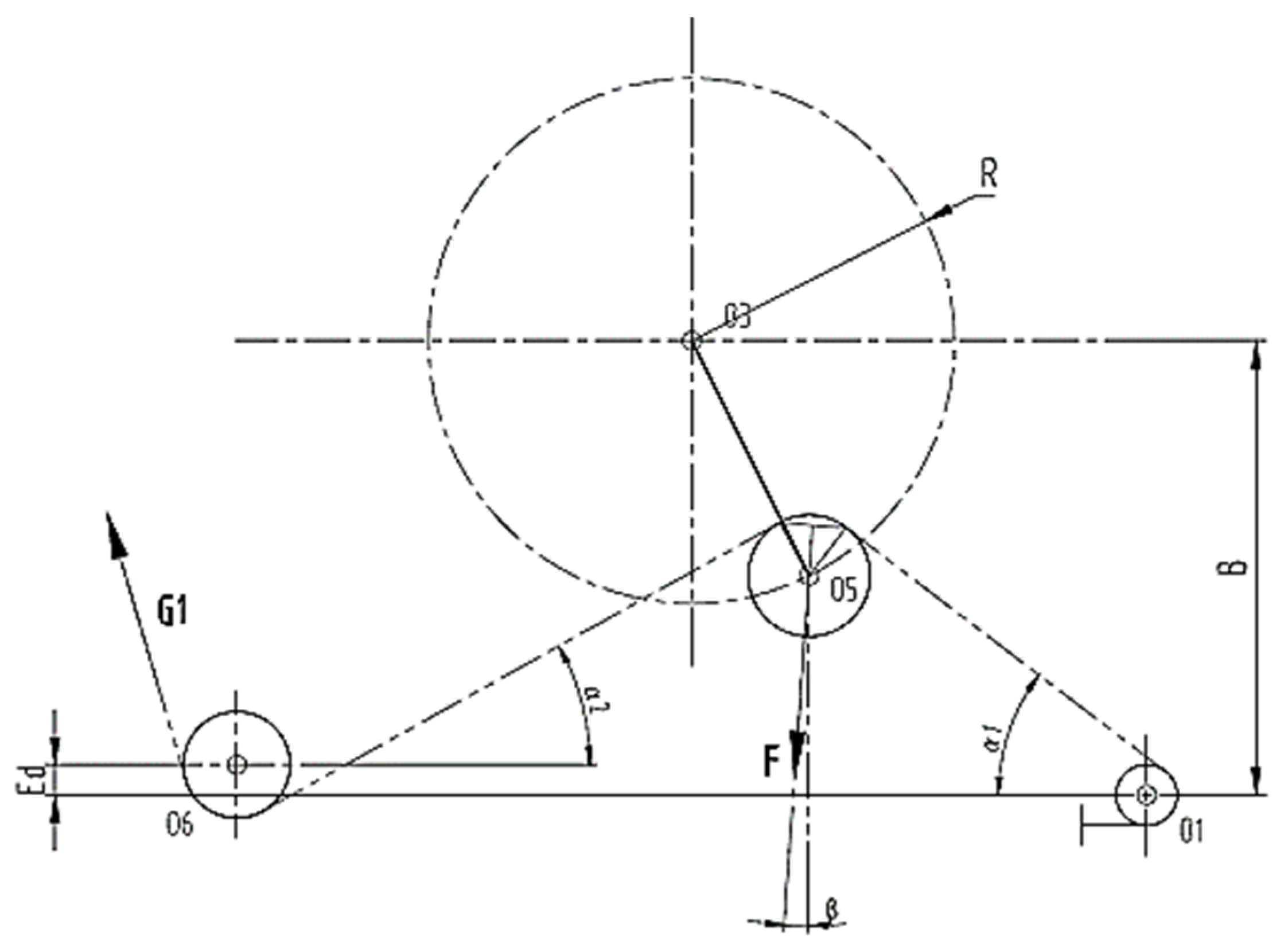
Figure 5.
Motion and force diagram of eccentric balance pumping unit.
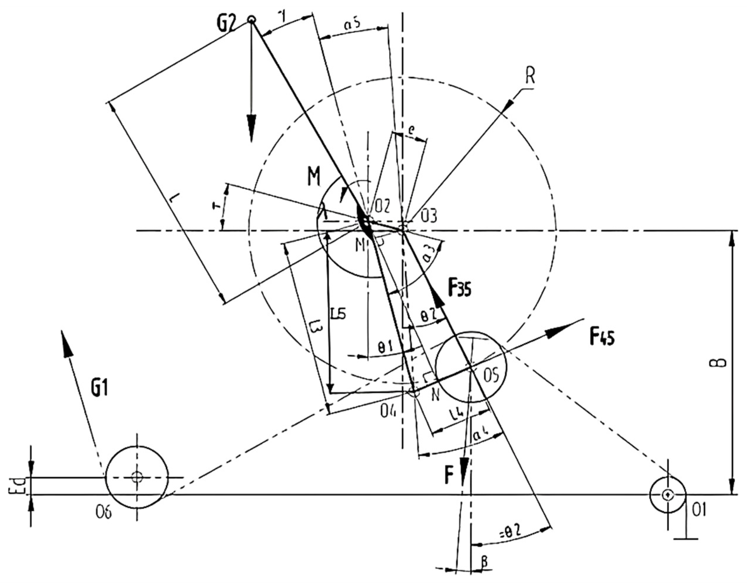
Figure 6.
Torque curves of the eccentric balance pumping unit.

Figure 7.
Virtual simulation model in ADAMS.

Figure 8.
Polished rod load variation curve.
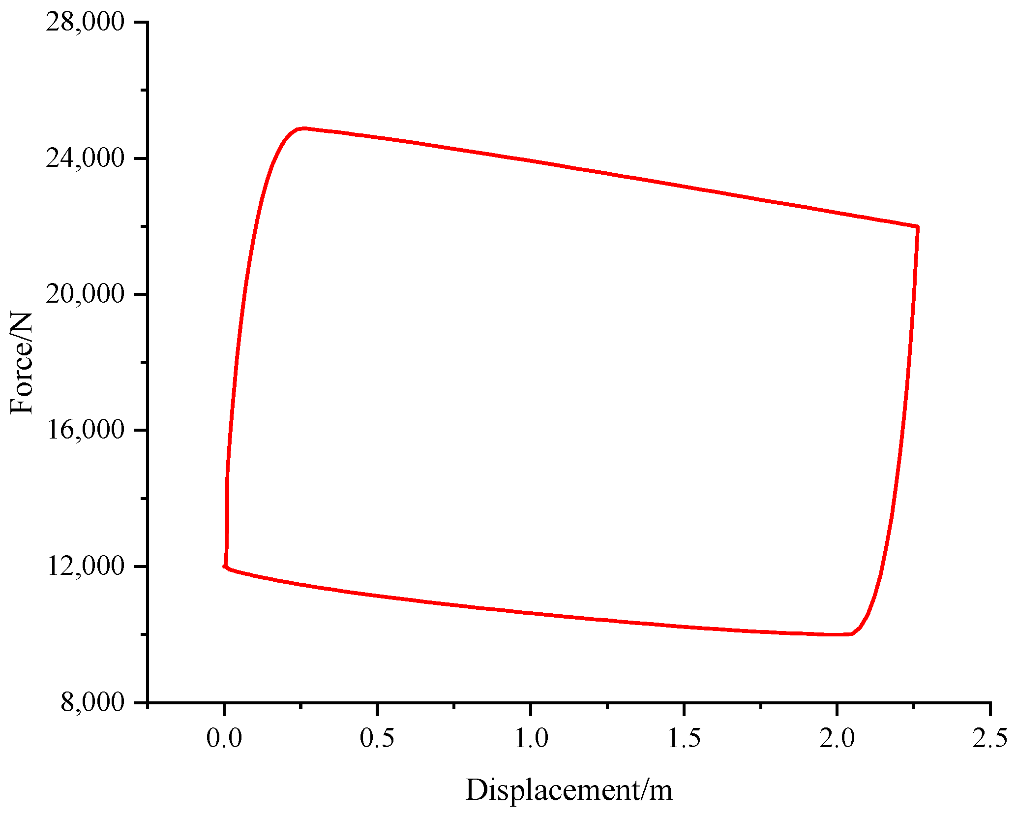
Figure 9.
Displacement, velocity and acceleration curve of polished rod.
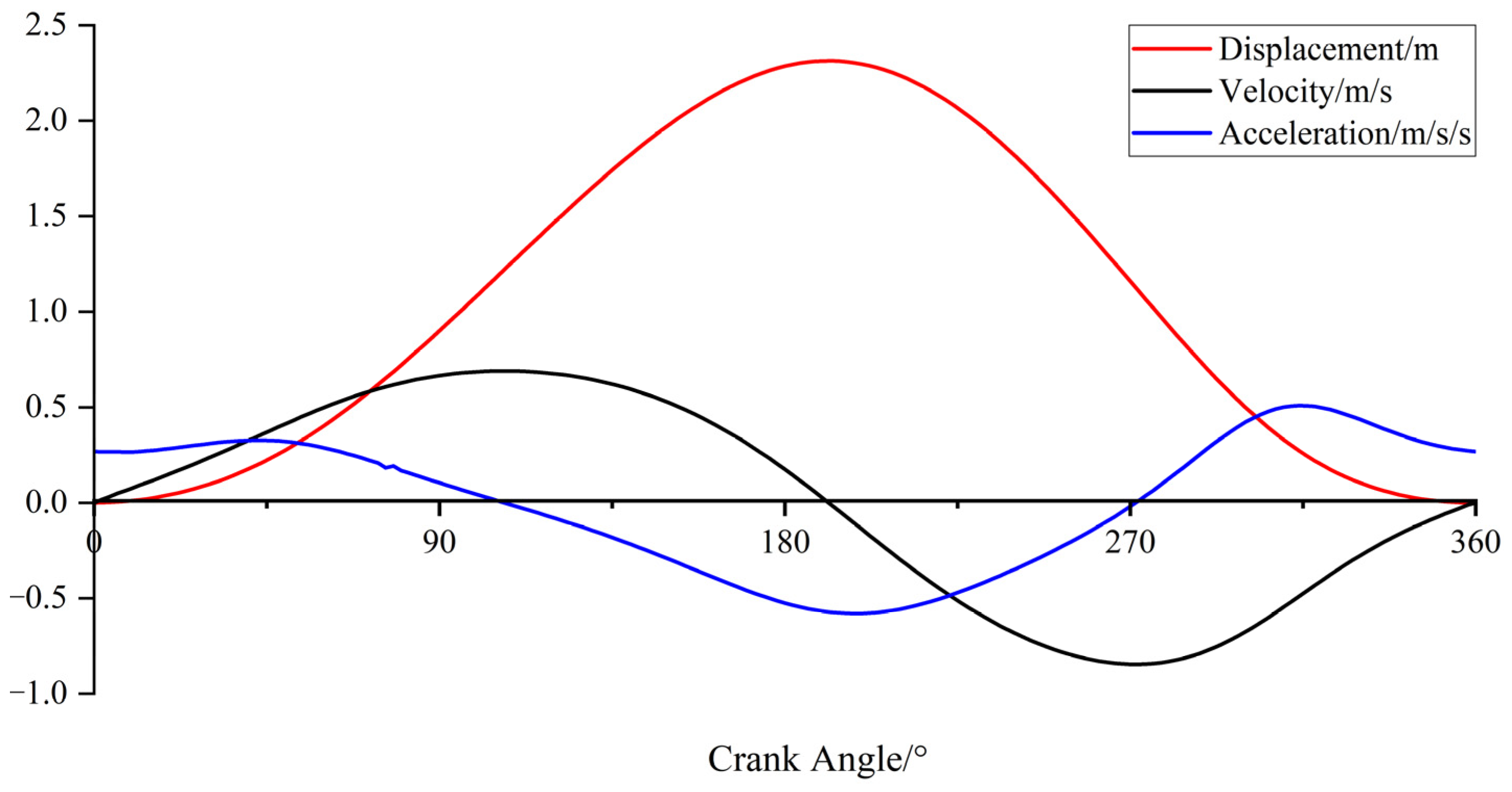
Figure 10.
Curves of angular velocity and angular acceleration of moving pulley connecting rod.

Figure 11.
Angular velocity and angular acceleration of moving pulley handle.
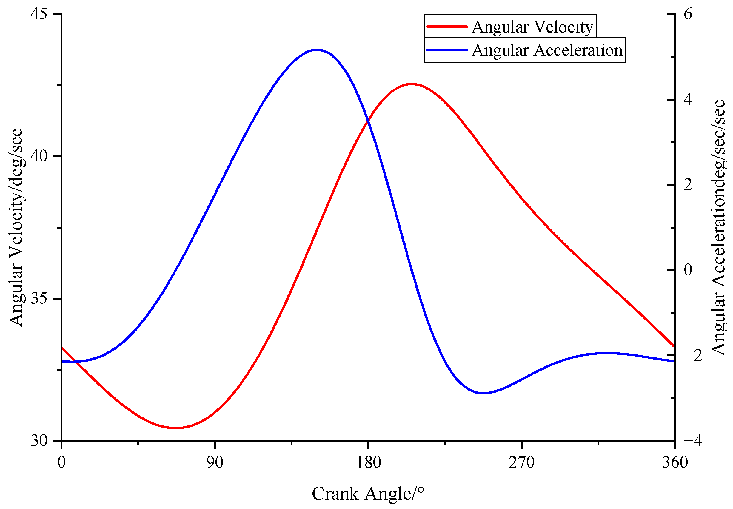
Figure 12.
Torque superposition curve of eccentric balanced pumping unit.
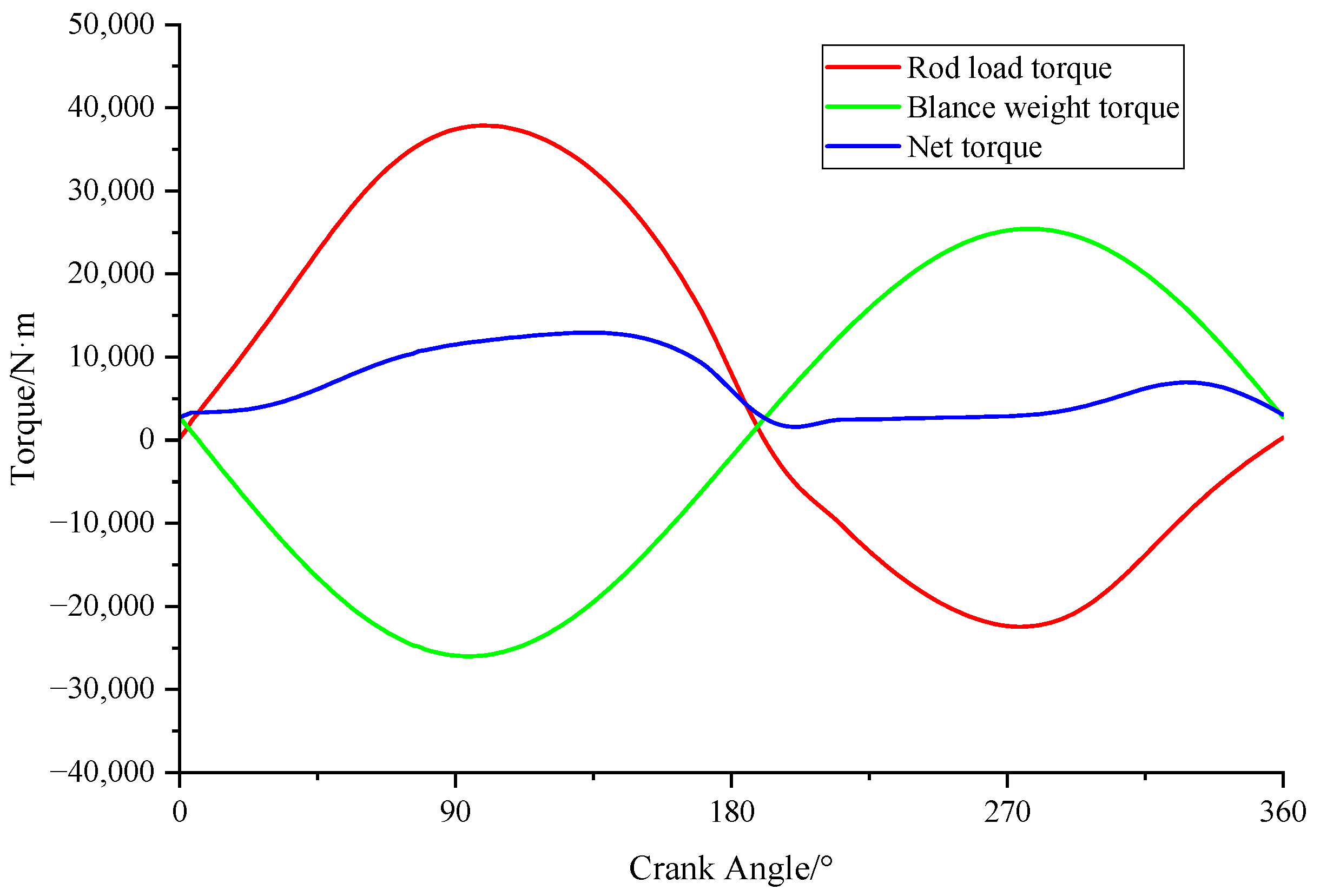
Figure 13.
The net torque curves at different angles.

Figure 14.
The net torque of the output shaft under different counterweight center of mass offset angles.
Figure 14.
The net torque of the output shaft under different counterweight center of mass offset angles.

Figure 15.
Torque curves of balance crank with different radii of center of mass.

Figure 16.
Torque curves under different rotating radii of pulley.

Figure 17.
Torque curves under different lengths of moving pulley connecting rod.
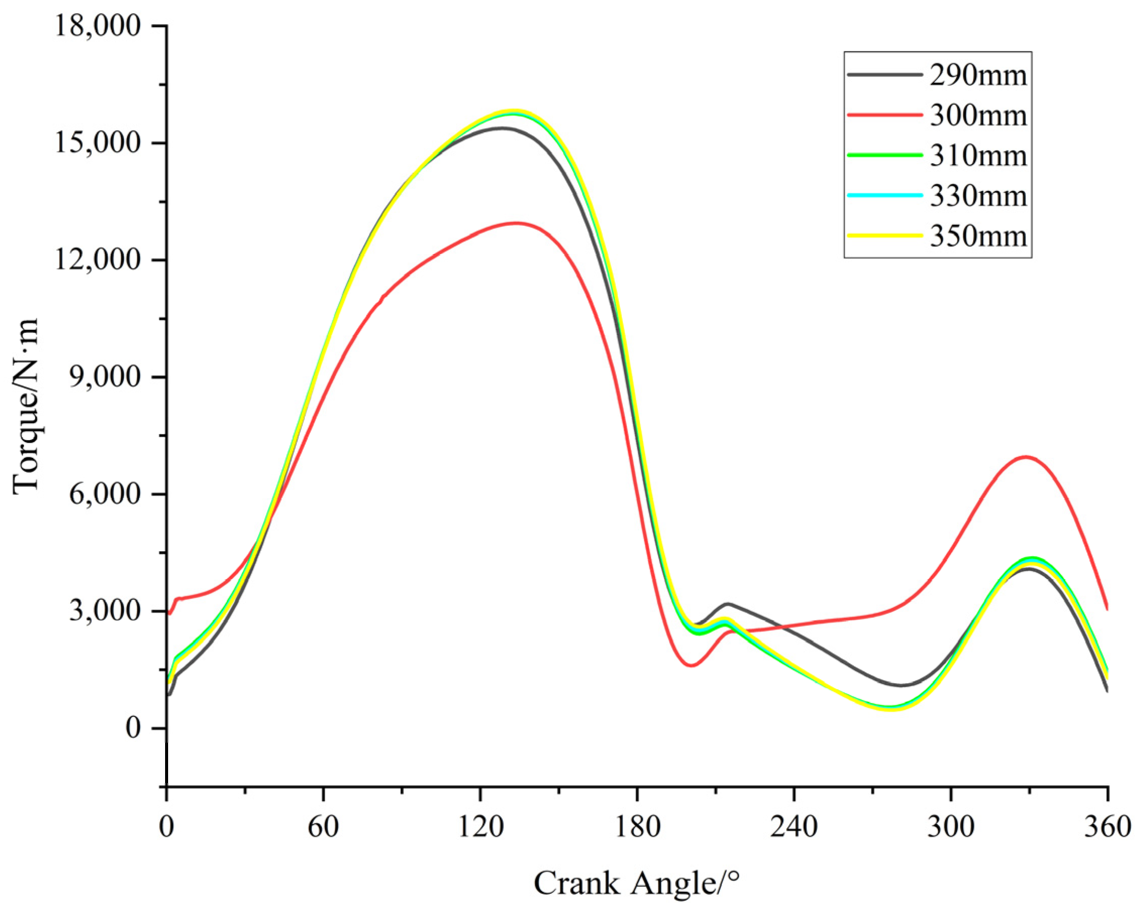
Figure 18.
Indoor test photos of eccentric balanced pumping unit.

Figure 19.
Measured current and power diagram of eccentric balanced pumping unit.

Figure 20.
Photo of eccentric flexible pumping unit in oil field application.

Table 1.
Quality of main components of eccentric balance pumping unit.
| Part Name | Quantity | Mass (kg) | |
|---|---|---|---|
| Single | Total | ||
| Balance crank | 1 | 869.2 | 869.2 |
| Counterweight | 2 | 492.6 | 985.2 |
| Pulley connecting rod | 3 | 29.5 | 29.5 |
| Pulley | 3 | 107.8 | 323.4 |
| Balance support | 2 | 6367.3 | 12,734.6 |
| Movable pulley handle | 1 | 238.3 | 238.3 |
| Main engine base | 1 | 19,781.2 | 237.4 |
Table 2.
Coordinates of balance crank center of mass under different offset angles.
| Offset Angle/° | X (m) | Y (m) | Z (m) |
|---|---|---|---|
| −40° | 0.18 | 4.06 | 2.18 |
| −30° | 0.43 | 4.31 | 2.18 |
| −20° | 0.58 | 4.46 | 2.18 |
| −10° | 0.73 | 4.56 | 2.18 |
| 0° | 0.93 | 4.76 | 2.18 |
| 10° | 1.08 | 4.81 | 2.18 |
| 20° | 1.13 | 4.91 | 2.18 |
| 30° | 1.36 | 5.02 | 2.18 |
| 40° | 1.64 | 5.16 | 2.18 |
Table 3.
The coordinates of the center of mass of the balance crank under different rotation radii.
| Radius (m) | X (m) | Y (m) | Z (m) |
|---|---|---|---|
| 0.9 | 0.96 | 4.34 | 2.29 |
| 1 | 1.06 | 4.54 | 2.29 |
| 1.3 | 1.16 | 4.74 | 2.29 |
| 1.4 | 1.36 | 5.02 | 2.29 |
| 1.5 | 1.52 | 5.15 | 2.29 |
Table 4.
Key component parameters of eccentric balance flexible pumping unit.
| Key Parameter | Optimal Value of Parameter |
|---|---|
| The balance crank angle δ | 165° |
| The counterweight center of mass offset angle λ | 30° |
| Rotating radius of counterweight center of mass of | 1.4 m |
| Counterweight | 1500 kg |
| Length of moving pulley handle | 0.85 m |
| Length of rotary pulley connecting rod | 300 mm |
Table 5.
Eccentric flexible pumping unit stability test parameters and results.
| Working Condition | Testing Items | Standard Value | Measured Value | Test Condition |
|---|---|---|---|---|
| Polished rod load: 15.20 kN Stroke: 2 m Pumping speed: 3 min−1 Motor power: 3 kW | Longitudinal amplitude at the top of bracket/mm | ≤3 | 1.6 |
|
| Lateral amplitude at the top of bracket/mm | ≤2 | 1.2 | ||
| Bearing temperature of reducer/°C | ≤70 | 30.5 | ||
| Temperature rise of reducer bearing/°C | ≤40 | 10.4 | ||
| Reducer oil pool temperature/°C | ≤70 | 29.2 | ||
| Reducer oil pool temperature rise/°C | ≤15 | 7.5 | ||
| Operation noise of the whole machine/dB | ≤85 | 78.4 |
Table 6.
Electrical parameter test data of eccentric balance pumping unit.
| Well Depth/m | Stroke/m | Pumping Speed/min−1 | Counterweight /kg | Balance Radius/m | Wellhead Pressure /MPa | Current/A | Power /kW | Displacement /L/min−1 |
|---|---|---|---|---|---|---|---|---|
| 70 | 2 | 3 | 630 | 1.4 | 3 | Imin = 1.96 | Pmin = 1.04 | 23.7 |
| Imax = 4.00 | Pmax = 2.36 | |||||||
| 2.5 | Imin = 1.43 | Pmin = 0.92 | ||||||
| Imax = 3.80 | Pmax = 2.31 | |||||||
| 2 | Imin = 1.60 | Pmin = 0.97 | ||||||
| Imax = 3.92 | Pmax = 2.36 |
Table 7.
Working parameters of oil well.
| Well Depth (m) | Pump Size (mm) | Stroke (m) | Pumping Speed (min−1) | Submergence (m) | Theoretical Displacement (m3/d) | Daily Liquid Production (t/d) | Daily Oil Production (t/d) | Water Cut (%) | Tubing Pressure (MPa) | Casing Pressure (MPa) |
|---|---|---|---|---|---|---|---|---|---|---|
| 880 | 38 | 2.5 | 4 | 60.13 | 16.3 | 5.44 | 0.6 | 89.15 | 0.46 | 0.42 |
Table 8.
Contrasting data of testing results.
| Type | Stroke (m) | Pumping Speed (min−1) | Pump Size (mm) | Maximum/Minimum Torque (kN·m) | Installed Power (kW) | Power Consumption per Ton of Liquid (kW·h) | System Efficiency (%) |
|---|---|---|---|---|---|---|---|
| Eccentric pumping unit | 2.5 | 4 | 38 | 25/7 | 3 | 1.5 | 24.3 |
| Beam pumping unit | 2.5 | 4 | 38 | 65/−15 | 15 | 3.3 | 14 |
Disclaimer/Publisher’s Note: The statements, opinions and data contained in all publications are solely those of the individual author(s) and contributor(s) and not of MDPI and/or the editor(s). MDPI and/or the editor(s) disclaim responsibility for any injury to people or property resulting from any ideas, methods, instructions or products referred to in the content. |
© 2024 by the authors. Licensee MDPI, Basel, Switzerland. This article is an open access article distributed under the terms and conditions of the Creative Commons Attribution (CC BY) license (https://creativecommons.org/licenses/by/4.0/).
Share and Cite
MDPI and ACS Style
Xu, J.; Wang, W.; Li, W.; Zhu, Q.; Lu, H. Kinematic and Dynamic Analysis of Eccentric Balanced Positive Torque Pumping Unit. Machines 2024, 12, 240. https://doi.org/10.3390/machines12040240
AMA Style
Xu J, Wang W, Li W, Zhu Q, Lu H. Kinematic and Dynamic Analysis of Eccentric Balanced Positive Torque Pumping Unit. Machines. 2024; 12(4):240. https://doi.org/10.3390/machines12040240
Chicago/Turabian StyleXu, Jinchao, Wensong Wang, Wei Li, Qijun Zhu, and Hui Lu. 2024. "Kinematic and Dynamic Analysis of Eccentric Balanced Positive Torque Pumping Unit" Machines 12, no. 4: 240. https://doi.org/10.3390/machines12040240
Note that from the first issue of 2016, this journal uses article numbers instead of page numbers. See further details here.