Abstract
The encased differential planetary gear system (EDPGS) allows power to be distributed among multiple output paths, enhancing efficiency and reducing weight. Uniform load distribution ensures stable system operation and prolongs service life. However, stochastic manufacturing errors leading to uneven load distribution pose challenges in engineering practice. To investigate the impact of floating support parameters on the load-sharing performance within an acceptable tolerance band, a dynamic model of the EDPGS considering time-varying meshing stiffness and random errors is established using the Monte Carlo method. This study employs the orthogonal experimental design method to analyze the effects of floating support stiffness and clearance on the load-sharing characteristics. The findings indicate that a larger sample size leads to a probability distribution of load-sharing coefficients closer to the Gaussian distribution, with minimal influence on the expectation and variance. Furthermore, this study highlights the significant influence of floating structure parameters on load-sharing characteristics in the encased stage systems compared to the differential stage. Decreasing floating support stiffness or increasing floating clearance proves beneficial in enhancing the load-sharing performance of the system.
1. Introduction
EDPGSs exhibit exceptional characteristics, such as high efficiency and power density, and are widely used in various fields, including ships, mining machinery, and helicopter transmission systems. The load-sharing performance plays a pivotal role in assessing the overall effectiveness of encased differential planetary gear trains, which hold immense significance in ensuring the efficient, reliable, and stable operation of mechanical systems. By achieving uniform load distribution, these gear trains can not only minimize energy loss and enhance transmission efficiency but also mitigate fatigue damage to crucial components, ultimately extending the service life of the system. Therefore, it is of great significance to study the load-sharing performance of EDPGSs.
There are many scholars that have carried out research on encased differential planetary gear systems. Wang [1] analyzed the effect of a planetary gear/star gear on the transmission efficiency of a closed differential double gear train. Kuznetsova et al. [2] investigated the influence of the parameters on eigenfrequencies of the oscillations of the dynamic model of differential closed planetary gearing. Zhu et al. [3,4,5] analyzed the dynamic floating displacement of center gear and meshing stiffness variation instabilities in an encased differential planetary gear train and studied the nonlinear dynamic behavior. Zhang et al. [6,7,8] studied the dynamic characteristic of a coaxial contrarotating encased differential gear train. Yang et al. [9] investigated the dynamic characteristic of an encased differential gear train with journal bearing. Despite the considerable research conducted by scholars on the dynamic characteristics of encased differential planetary gear systems, there remains a lack of in-depth investigation into the floating support structures and their load-sharing characteristics.
Although there is not extensive research on the load-sharing characteristics of encased differential planetary gear systems, many studies have been carried out on the load-sharing behavior of planetary gear systems. Yang et al. [10] discussed the effects of operating parameters and structural parameters on the load-sharing characteristic of planetary gear systems. Ryali et al. [11] built a hybrid planetary dynamic load distribution model and studied the effects of planet carrier flexibility on both the quasi-static and dynamic response of planetary gear sets. Che et al. [12] investigated the influence of the bolt constraint parameters on the dynamic characteristic of the planetary gear transmission system. Zhang et al. [13] studied the load-sharing performance of the prototype through a scale model of PGTS, and the model was verified by physical experiments. Yoo et al. [14] investigated the effect of flexible pins on the improvement of tooth load sharing and distribution in the planetary gear set of a wind turbine gearbox. Xu et al. [15] conducted research on the effects of positioning errors of the mesh position and the corner contact on the load-sharing characteristics of a planetary gear set. Zhang et al. [16] built a lumped parameter dynamic model of a compound planetary gear set and investigated the influence of floating support from different components on loading-sharing behavior and periodic motion. The studies conducted by these scholars provide guidance for the research presented in this paper.
Further, some scholars apply mathematical statistical methods to the dynamic research of gear systems. Fang et al. [17] presented a stochastic nonlinear gear dynamic model considering the stochastic external excitations, and the effects of the stochastic driving speed and external load on gear dynamic characteristics were investigated by Monte Carlo simulation. Diez et al. [18] evaluated the impact of the planetary gears manufacturing processes’ uncertainties on the transmission performance based on the Monte Carlo method and Taguchi’s method. Zhang et al. [19] carried out a reliability sensitivity analysis to demonstrate the effects of the tooth modification parameters on the dynamic transmission error fluctuations of the helical planetary gear train based on the Monte Carlo method. Ali et al. [20] proposed a new approach to determining the effect of random manufacturing errors on the vibrations measured on the bearings of mating gears, and different levels of random manufacturing error are investigated based on the Monte Carlo method. Jin et al. [21] analyzed the influence of backlash and center distance error on the load-sharing characteristics based on orthogonal test method. Hu et al. [22] investigated error randomness in dynamic load-sharing behavior on the closed differential planetary transmission system based on the Monte Carlo method.
Currently, there have been numerous studies investigating the dynamic load-sharing characteristics of EDPGSs. However, no research paper has been identified to date that specifically addresses the load-sharing characteristics of single-input and dual-output EDPGSs. Additionally, the gear processing errors fall within the specified tolerance band range. Consequently, there is a need to employ statistical methods to investigate the load-sharing characteristics of enclosed differential planetary gear trains, which has been a relatively underexplored area in the literature. Therefore, it is essential to conduct a study on the load-sharing behavior of single-input and double-output closed differential planetary system structures using mathematical statistical methods.
This paper presents a dynamic model that considers floating support parameters under random error conditions for an EDPGS. The model incorporates the effects of time-varying mesh stiffness, manufacturing errors, and installation errors. The Monte Carlo method and orthogonal experimental design are utilized in the analysis. Moreover, this study investigates the influence of floating support stiffness and floating clearance on the load-sharing performance of the gear system. These findings offer valuable guidance and references for the design of floating structures.
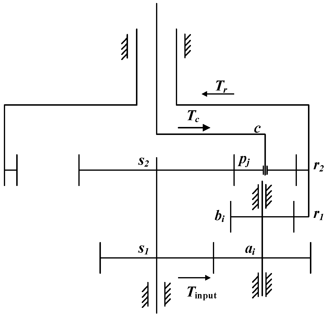
2. The Physical Model of the EDPGS
The EDPGS in this paper is a single-input and dual-output configuration, and constant velocity reverse rotation of the internal and external rotor shafts can be achieved through structural parameter design. The system consists of the encased stage and the differential stage, as shown in Figure 1. The encased stage system is composed of sun gear s1, star gear ai, bi(i = 1, 2, …, M), and inner ring gear r1, and the differential stage system is composed of sun gear s2, planetary gear pj(j = 1, 2, …, N), and inner ring gear r2. When the load torque of the internal and external rotor shafts is equal, the power transmission of the system can be divided into three paths. The path 1 route is s1-ai-bi-r1-r2-Tr, the path 2 route is s1-s2-pj-r2-Tr, and the path 3 route is s1-s2-pj-c-Tc.

Figure 1.
The diagram of the EDPGS.
3. Dynamic Model of the EDPGS Based on the Monte Carlo Method
3.1. Time-Varying Meshing Stiffness
Since the coincidence of spur gears is generally not an integer and is less than two, there exists alternating meshing of single and double teeth, resulting in periodic fluctuations in gear meshing stiffness. The time-varying meshing stiffness can be calculated by Equation (1) [12]:
where represents the comprehensive meshing stiffness of the gear pair m, is the stiffness fluctuation value, an and bn are the Fourier transform coefficient, and ω is the meshing period of the gear pair. The calculation of stiffness parameter values can be referred to in Equations (2) and (3):
where denotes the single contact stiffness, denotes the comprehensive meshing stiffness, which can refer to the ISO 6336-1 [23], and εm denotes the contact ratio of the gear pair.
The meshing damping [24] of the gear pair can be expressed as the following:
where ξm is the meshing damping ratio of the gear, the value ranges from 0.03 to 0.17, Im is the moment of inertia (1 corresponds to the driving gear, 2 corresponds to the driven gear), and rm is the radius of the base circle of the gear.
The contact stiffness of the rolling bearing is equal to the tandem of the inner and outer raceway stiffness, which can be expressed as the following:
where the contact stiffness between the rolling element and the inner and outer raceways kci and kco are shown as follows:
where ΔFr is the variation in radial load, Δδi is the contact deformation between the rolling element and the inner raceway under ΔFr, and Δδo is the contact deformation between the rolling element and the outer raceway under ΔFr.
Rolling bearing oil film stiffness can be calculated by the following:
where h′ is the thickness of the oil film between the rolling element and the inner and outer raceways.
Considering the elastic deformation of the bearing and the lubricating oil film, the comprehensive radial stiffness of the bearing can be obtained as the following [25]:
3.2. Stochastic Equivalent Meshing Error Based on the Monte Carlo Method
The gear transmission error is a significant parameter in the dynamic model, exerting substantial influence on dynamic behavior [26]. It is typically regarded as a constant value [27]. However, the error is random in the actual machining process as long as the error is within the required tolerance range and can be regarded as meeting the requirements of machining accuracy. In order to consider the influence of the tolerance band on the load-sharing performance, this paper adopts the following assumptions:
- (1)
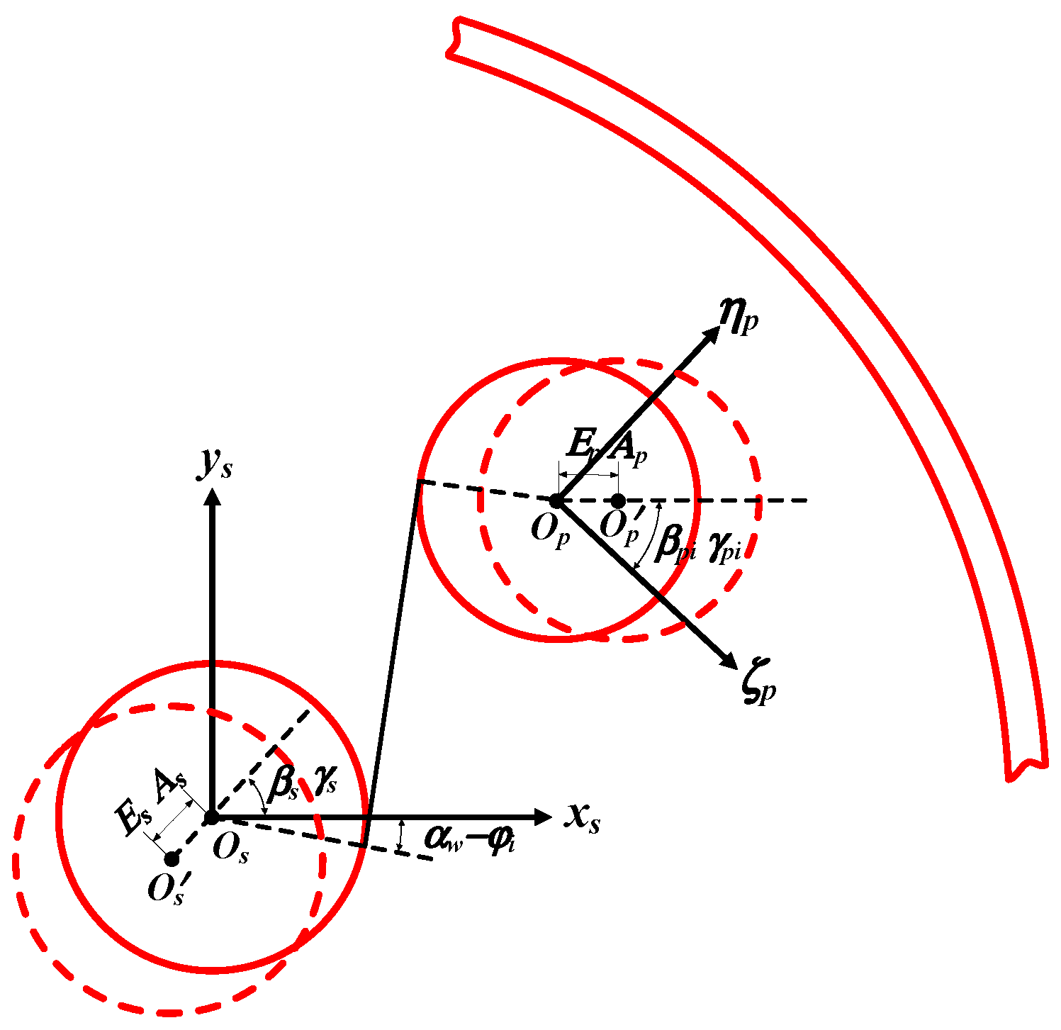
- The influence of the eccentricity error and installation error is mainly considered, and the error schematic diagram of the sun gear and planetary gear is shown in Figure 2.
 Figure 2. Schematic diagram of eccentricity error and installation error of the sun gear and the planetary gear.
 - (2)
- The Monte Carlo method is used to simulate random eccentricity error and installation error. Assuming that the error machining accuracy in this paper is grade 5, the range of the tolerance band is considered to be between grade 4 and grade 6.
Taking the differential stage system as an example, the eccentricity and installation errors of the external meshing pair are shown as Equation (9):
where Es0, As0, Ep0, and Ap0 are the eccentricity error amplitude and the installation error amplitude of the sun gear and planetary gear under grade 4, respectively, and Es1, As1, Ep1, and Ap1 are the eccentricity error amplitude and the installation error amplitude of the sun gear and planetary gear under grade 6, respectively. rand (0,1) represents a random number taken in the interval range [0, 1]. ωs and ωc are the angular velocity of the sun gear and the planetary carrier, respectively, and when the system is a fixed shaft gear train, ωc = 0. αw is the meshing angle of the external meshing gear pair, φi is the position angle of the ith planetary gear relative to the initial position, which can be expressed as φi = 2π(i − 1)/Np + φ0, φ0 is the initial position angle, and Np is the number of planetary gears. βs and γs are the initial phase of manufacturing and installation errors of the sun gear, respectively. βpi and γpi are the initial phase of manufacturing and installation errors of the planetary gears.
The eccentricity and installation errors of the internal meshing pair are shown as Equation (10):
where αn is the meshing angle of the inner meshing pair, and βr and γr are the initial phases of the eccentricity error and the installation error of the internal ring gear, respectively.
The equivalent meshing error [28] of the gear pair is as follows:
3.3. Dynamic Modeling of Support Reaction Forces in Floating Structures
The floating structure refers to the central components floating freely with no radial support within a certain floating range. It can adjust the radial displacement to improve the load-sharing performance automatically, and the essence is to increase the degree of freedom of the components and eliminating or reducing virtual constraints through the floating of the basic component to achieve the purpose of load sharing. The central components can be floated by mechanisms such as cross sliders, couplings, etc.
The reaction force of the floating sun gear is shown in Figure 3, which can refer to Equations (12) and (13) [29]. When , the sun gear is in an unconstrained state which can float freely in the x direction; when or , the vibration displacement of the sun gear reaches the maximum allowable floating amount, and the reaction force is provided by the bending deformation of the gear shaft. The supporting forces along the y-axis are similar to those in the x-axis direction.
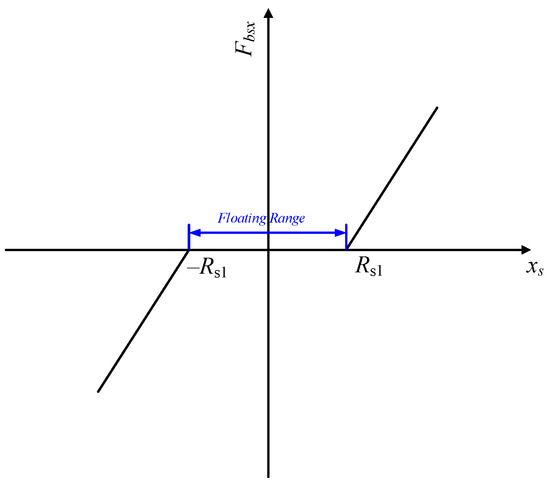
Figure 3.
Schematic diagram of the reaction force of the floating sun gear.
3.4. Overall System Dynamic Model
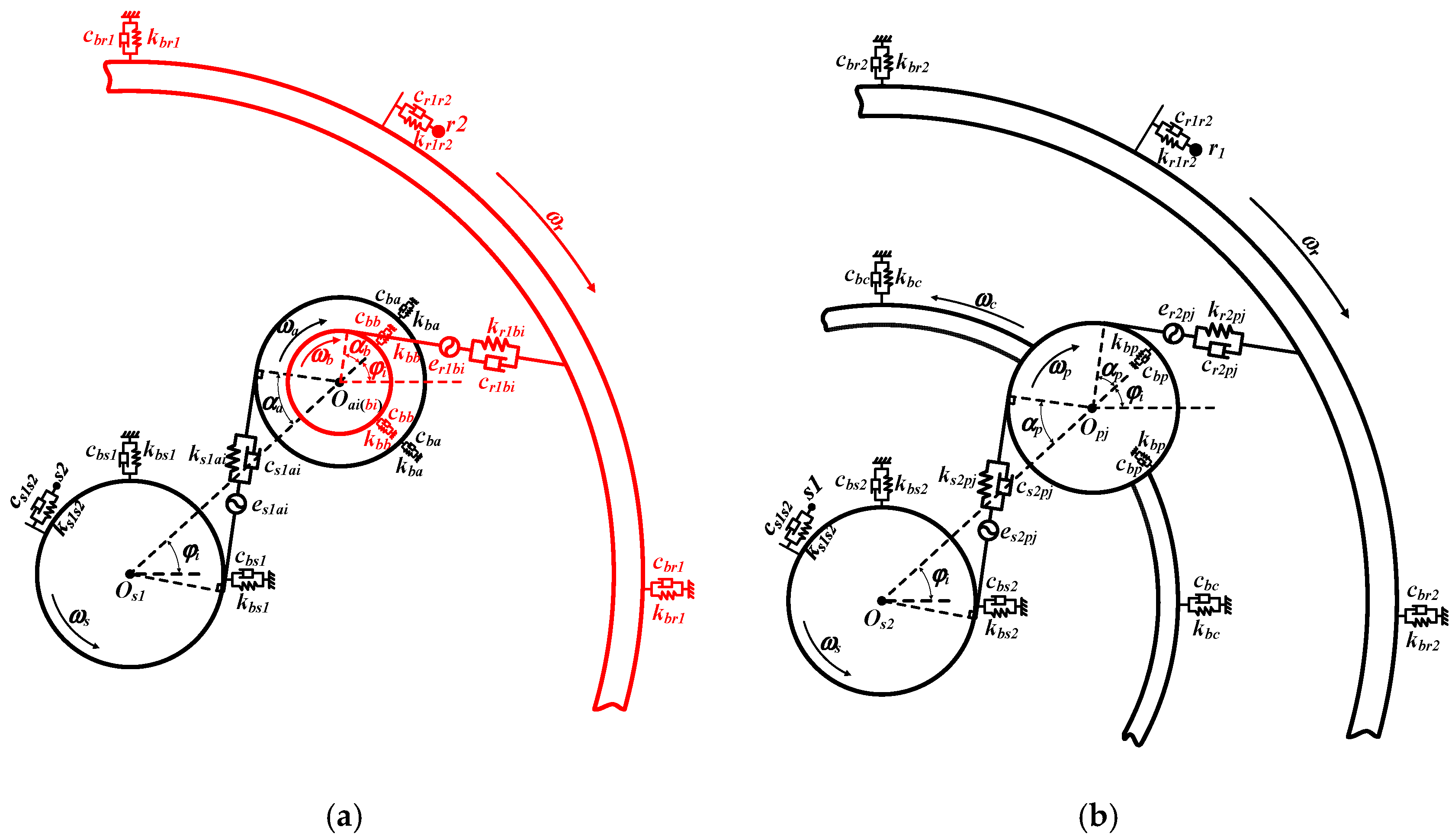
Since the gears in this paper are all spur gears, the degrees of freedom in the axial and oscillating directions can be ignored, and the degrees of freedom in the bending and torsion directions can be considered. The EDPGS has (15 + 6M + 3N) DOFs, and its generalized coordinates are as follows:
where r1, s1, ai, and bi represent the internal gear, sun gear, first stage star gear, and second stage star gear of the encased stage system. r2, s2, c, and pj represent the internal gear, sun gear, carrier, and planetary gear of the differential stage system. M and N represent the number of star gears and planetary gears, which are both taken as 3 in this paper. x, y, and ϕ represent the horizontal displacement, vertical displacement, and torsional displacement of the components. ζ and η are the radial and tangential displacements of the star gear or planetary gear.
X = (xr1, yr1, ϕr1, xs1, ys1, ϕs1, ζai, ηai, ϕai, ζbi, ηbi, ϕbi, xr2, yr2, ϕr2, xs2, ys2, ϕs2, xc, yc, ϕc, ζpj, ηpj, ϕpj)T
(i = 1, 2, …, M, j = 1, 2, …, N)
(i = 1, 2, …, M, j = 1, 2, …, N)
The relative meshing displacement of the star gear train or planetary gear train meshing pair along the direction of the meshing line can be expressed as follows:
where Vmn represents the meshing vector, with the external meshing shown in Equation (15) and the internal meshing shown in Equation (16). qmn represents the degree of freedom involved in meshing, as shown in Equation (17). emn represents the equivalent meshing error of the meshing pair mn, which can refer to Equation (12). When the system is a star gear train, m = s1, r1, n = ai, bi (i = 1, 2, …, M). When the system is a planetary gear system, m = s2, r2, n = pj (j = 1, 2, …, N).
When the meshing form is external meshing, ψmn = αm − φi, and when the meshing form is internal meshing, ψmn = αm + φi. αm represents the pressure angle of component m.
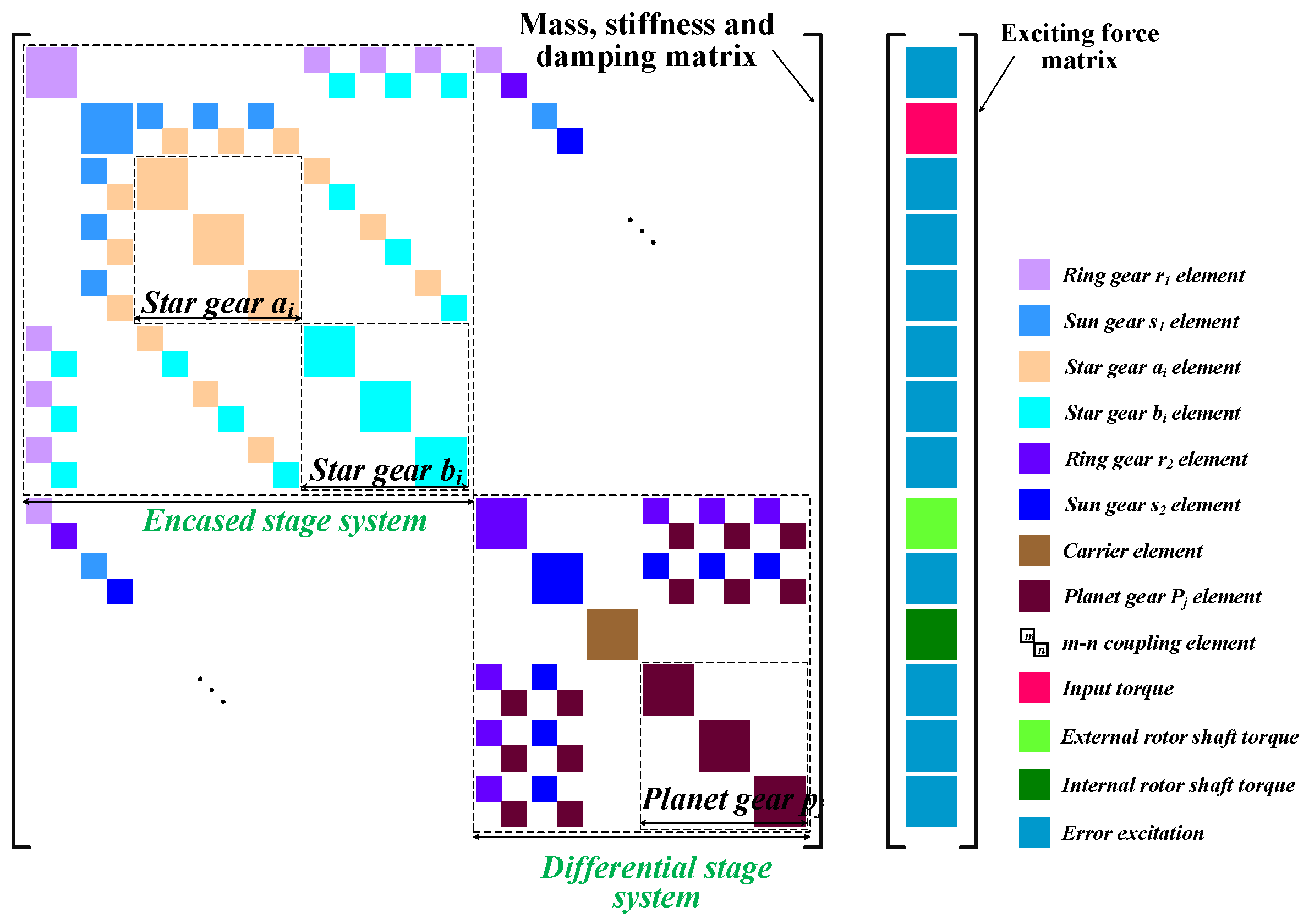
Figure 4 shows the dynamic model of the EDPGS. The Lagrange equation is used to derive the dynamic equation, and the derivation process can be referred to in [30], which is no longer mentioned in this article. The overall dynamic matrix is the following:
where M is the mass matrix, C is the damping matrix, G is the gyroscopic matrix, Kb is the support stiffness matrix, Km is the meshing stiffness matrix, Kω is the centrifugal stiffness matrix, and Q is the excitation vector. Figure 5 shows the dynamic matrix assemble rule.
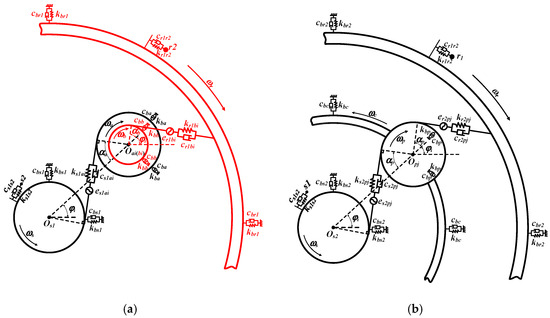
Figure 4.
Dynamic model of EDPGS: (a) encased stage; (b) differential stage.
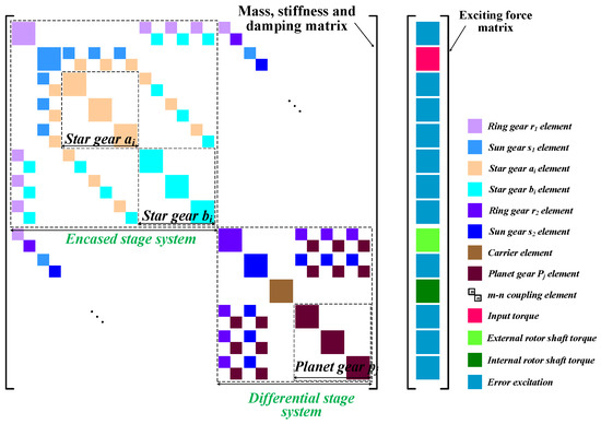
Figure 5.
Schematic diagram of dynamic matrix assemble rule.
3.5. Calculation Model of Load-Sharing Coefficient
The load-sharing coefficient (LSC) is used to describe the load distribution of the star gear system or planetary gear system over a period of time, which can be calculated from Equations (18) and (19). The smaller the LSC, the better the load-sharing performance of the system.
Here, , , , and are the maximum LSCs of the sun gear–star gear pair, inner ring gear–star gear pair, sun gear–planetary gear pair, and inner ring gear–planetary gear pair in a meshing cycle in the ith sample trial, respectively. M is the number of star gears and planetary gears, and N is the number of random samples. Fi(i = s1a, r1b, s2p, r2p) refers to the dynamic meshing force of ith gear pair.
Load-sharing performance under random samples based on the Monte Carlo method can be properly estimated by mathematical expectations and variances. The expectation and variance of the LSC in a single stage can be obtained by Equations (20) and (21):
4. The Analysis of the Load-Sharing Characteristics of the EDPGS
4.1. Dynamic Parameter of the Encased Differential Planetary System
In order to conduct a dynamic analysis of the encased differential planetary system, structural and dynamic parameters are needed. Table 1 shows the structural parameters of the EDPGS, Table 2 shows the dynamic parameters of the EDPGS, Table 3 shows the error parameters of the EDPGS, and the gear error is given according to the four-grade machining accuracy [31]. This paper assumes that the input speed of the system is 1500 r/min and that the input torque is 12,000 Nm.

Table 1.
Structural parameters of EDPGS.
Table 2.
Dynamic parameters of EDPGS.
Table 3.
Error parameters of EDPGS under grades 4 and 6.
4.2. Orthogonal Experimental Design Based on Floating Support Stiffness and Clearance
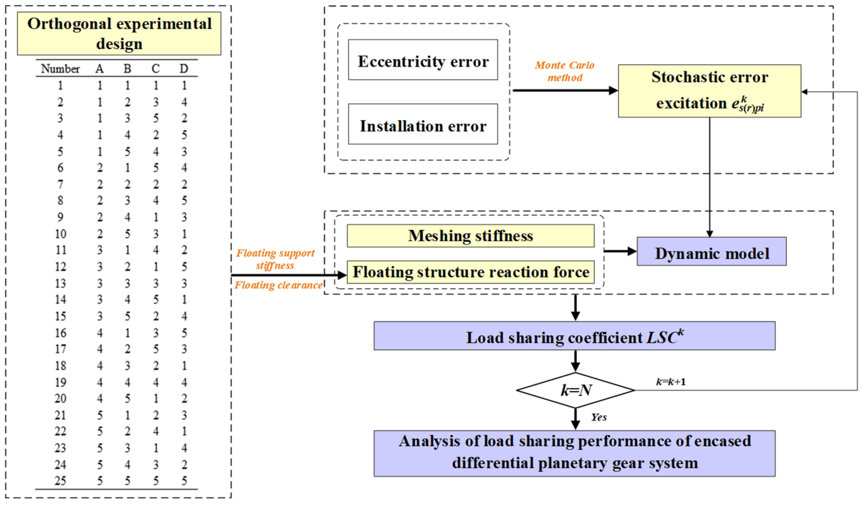
Due to the diversity of parameter combinations, it is difficult to consider the load-sharing performance of the EDPGS under all combinations under a large sample number. Therefore, the orthogonal experimental design method can be used to investigate the influence of floating support stiffness and floating clearance on the load-sharing characteristics of the system. An orthogonal experimental design method is a mathematical statistical method that uses an “orthogonal table” to arrange and analyze multi-factor experiments, which can obtain as much information as possible through effective data combination, and has the characteristics of fewer tests and high efficiency. The experimental steps of orthogonal experimental design are as follows:
- (1)
- Determine the experimental factors and levels.
- (2)
- Build the experimental matrix X, ensuring that each level of each experimental factor appears exactly once and that every pair of columns in the experimental matrix is orthogonal. The building method can refer to a Latin hypercube, orthogonal fractional array, etc.
- (3)
- Conduct experiments according to the design in the experimental matrix and record the resulting data.
The floating support stiffness considers four parameters, namely encased stage sun gear support stiffness, encased stage inner ring gear support stiffness, differential stage sun gear support stiffness, and differential stage inner ring gear support stiffness, and each parameter is divided into five levels, namely 1 × 10⁷ Nm, 5 × 10⁷ Nm, 1 × 10⁸ Nm, 5 × 10⁸ Nm, and 1 × 10⁹ Nm. Hence, a four-factor, five-level orthogonal test table is adopted which can be generated by SPSS software, as shown in Table 4. Among them, A, B, C, and D represent the four factors that need to be studied, and 1~5 represents the five levels corresponding to each factor. The rule of variation in LSCs with the changing of support stiffness can be evaluated through 25 trials.
Table 4.
Four-factor, five-level orthogonal test table.
Since the ring gear adopts the dual structure and is directly connected to the external rotor shaft, it is not easy to use floating structure. In addition, the large mass of the double inner ring gear results in the small floating amount of the ring gear. Therefore, this paper only considers the influence of the floating clearance of the sun gear of the encased stage and the differential stage on the load-sharing performance of the system. The clearance is divided into four levels, namely 10 μm, 20 μm, 30 μm, and 40 μm. So, a two-factor, five-level orthogonal test table is adopted, as shown in Table 5. The rule of variation in LSCs with the changing of floating clearance can be evaluated through 16 trials.
Table 5.
Two-factor, four-level orthogonal test table.
4.3. Analysis Process of EDPGS Based on Mathematical Statistical Methods
Figure 6 shows the flowchart of the analysis process of the EDPGS based on mathematical statistical methods. The parameter allocation values obtained according to the orthogonal experimental design table were substituted, and then the random error excitation was generated according to the Monte Carlo method, which was substituted into the dynamic model, and LSCk was obtained by the Newmark method. When the number of iterations k reaches the expected value N, the statistic load-sharing coefficient and floating displacement of the sun gear—including the expectation, standard deviation, and probability distribution—can be obtained. Moreover, the analysis of load-sharing performance of the EDPGS can be conducted.

Figure 6.
Flowchart of analysis process of EDPGS based on mathematical statistical methods.
4.4. Analysis of Load-Sharing Performance of EDPGS Based on the Monte Carlo Method
The load-sharing performance of the EDPGS can be obtained through the analysis of a large number of random samples based on the Monte Carlo method. The results of the analysis are more accurate when the number of samples tends to infinity under theoretical conditions. However, due to the limitation of calculation conditions, it is necessary to obtain an appropriate sample size for subsequent analysis. Hence, the probability distribution of LSC under the sample sizes of N = 100, N = 300, and N = 500 are compared.
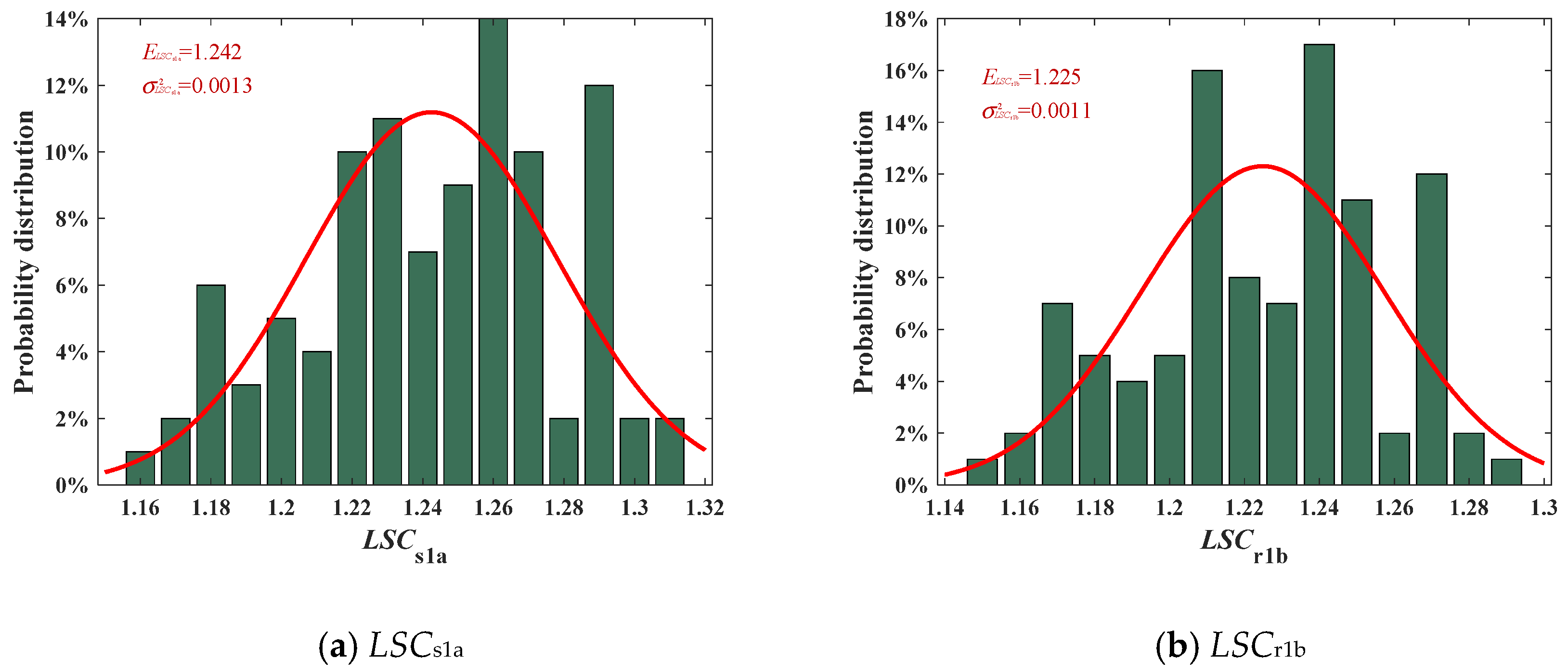
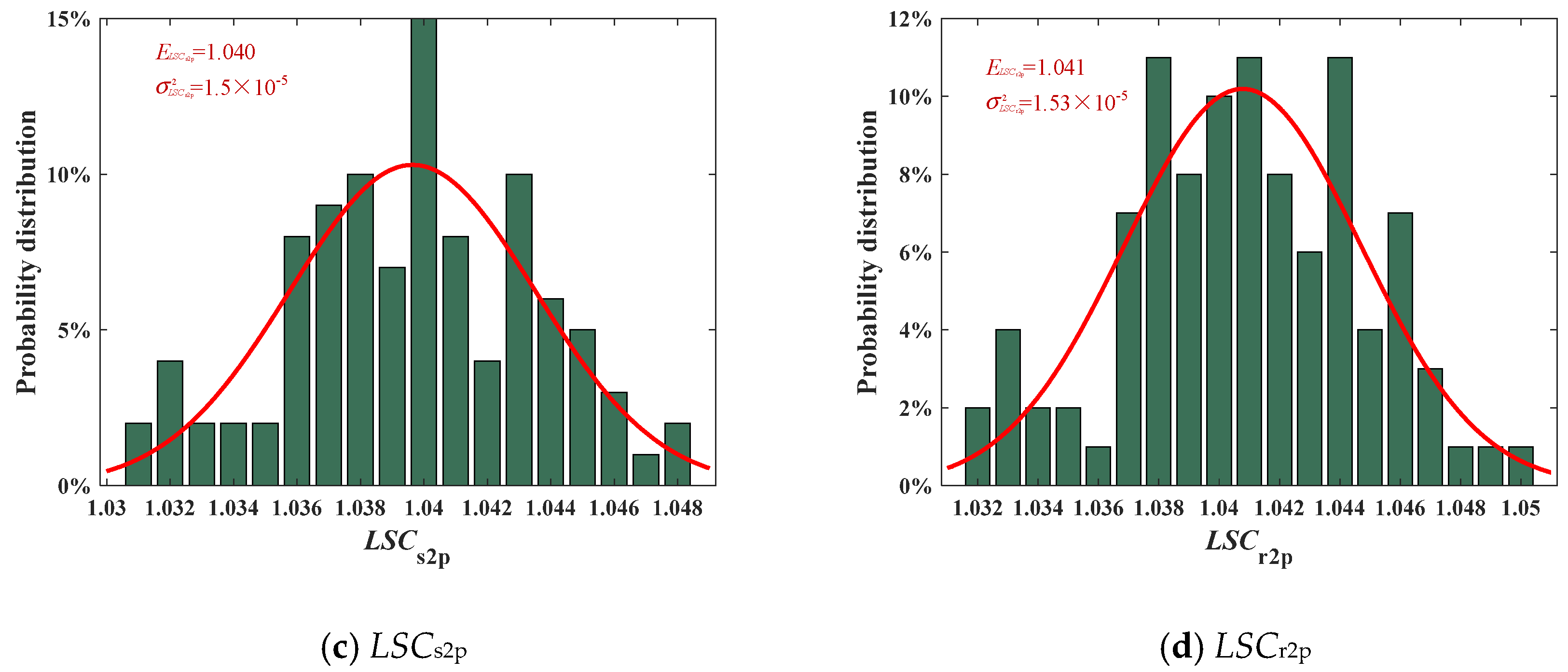
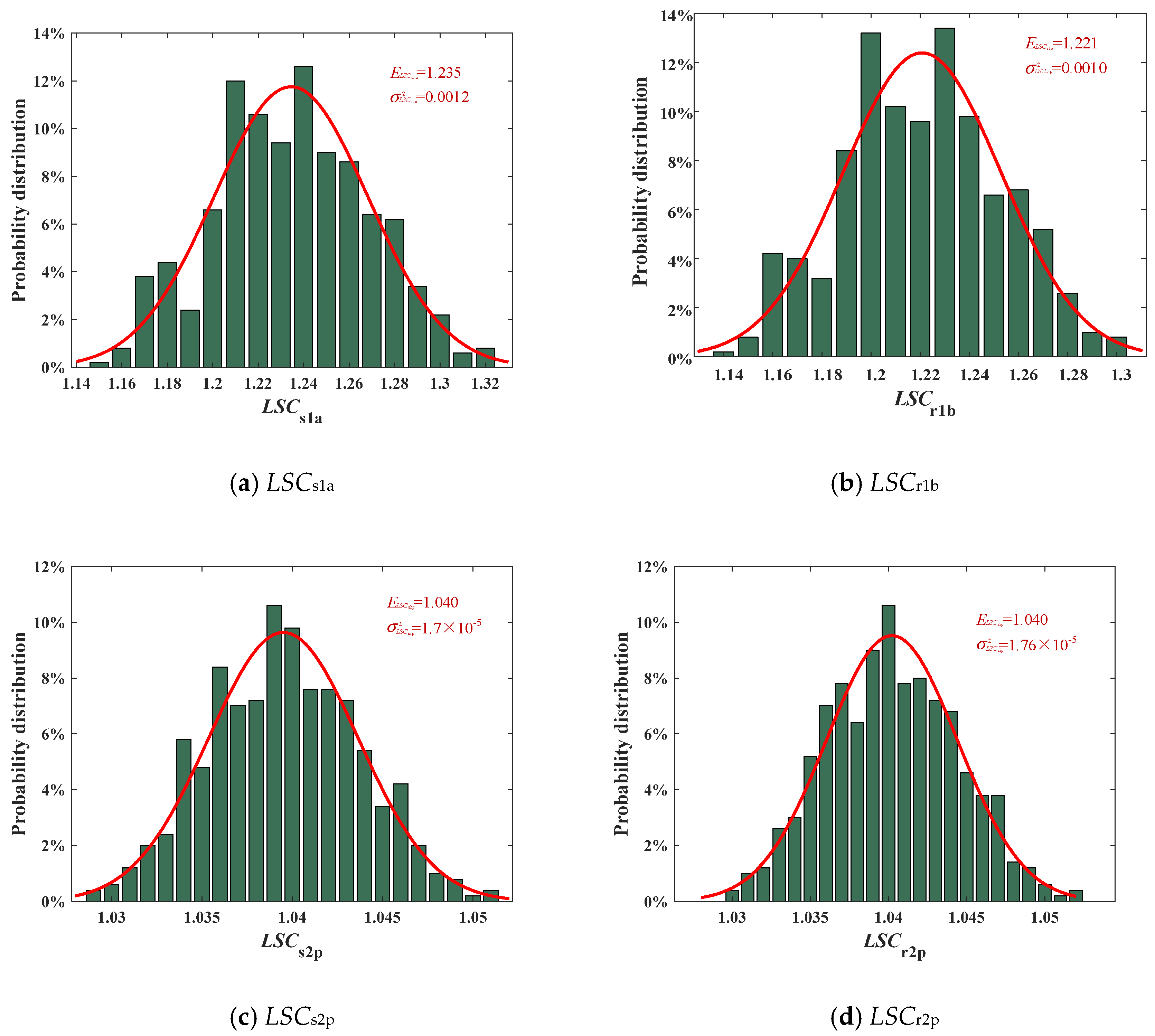
Figure 7, Figure 8 and Figure 9 show the probability statistic histogram of load-sharing behavior in the EDPGS under N = 100, N = 300, and N = 500, respectively. A Gaussian distribution curve was fitted to match the statistical distribution. It can be seen from the (a) and (b) from Figure 7, Figure 8 and Figure 9 that the interval ranges of LSCs1a are [1.16, 1.31], [1.15, 1.31], and [1.15, 1.32], the expectations are 1.242, 1.231, and 1.235, and the variances are 0.0013, 0.0012, and 0.0012, respectively. And the interval ranges of LSCr1b are [1.15, 1.29], [1.14, 1.29], and [1.14, 1.30], the expectations are 1.225, 1.218, and 1.221, and the variances are 0.0011, 0.0011, and 0.0010, respectively. It can be drawn that the probability distributions of LSCs1a and LSCr1b are quite different from the fitted Gaussian distribution when the sample number N = 100, while when the sample number N = 300 or 500, the distributions of LSCs1a and LSCr1b are similar to the fitted Gaussian distribution. From the perspective of expectation and variance, the gap is not very large. From (c) and (d) from Figure 7, Figure 8 and Figure 9, the interval ranges of LSCs2p are [1.16, 1.31], [1.15, 1.31], and [1.15, 1.32], the expectations are 1.242, 1.231, and 1.235, and the variances are 0.0013, 0.0012, and 0.0012, respectively. And the interval ranges of LSCr2p are [1.15, 1.29], [1.14, 1.29], and [1.14, 1.30], the expectations are 1.225, 1.218, and 1.221, and the variances are 0.0011, 0.0011, and 0.0010, respectively. In summary, the following four conclusions can be drawn.
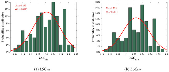

Figure 7.
Probability statistic histogram of load-sharing behavior in the EDPGS under N = 100.
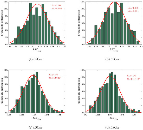
Figure 8.
Probability statistic histogram of load-sharing behavior in the EDPGS under N = 300.
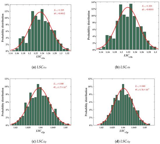
Figure 9.
Probability statistic histogram of load-sharing behavior in the EDPGS under N = 500.
First, the probability distribution of the differential stage system is more similar to the Gaussian distribution than the encased system under the same sample number. Second, the higher the sample number, the more similar the probability distribution is to the Gaussian distribution under the same stage system. Third, the load-sharing performance of the differential stage system is better than that of the encased stage system. Forth, sample number has less effect on expectations and variance. Therefore, the sample number of this paper is taken as 300, and an ideal expectation can be obtained while the probability distribution is similar to the Gaussian distribution. Moreover, the calculation time is reduced.
4.5. The Effect of Floating Support Stiffness on the Load-Sharing Performance of EDPGS
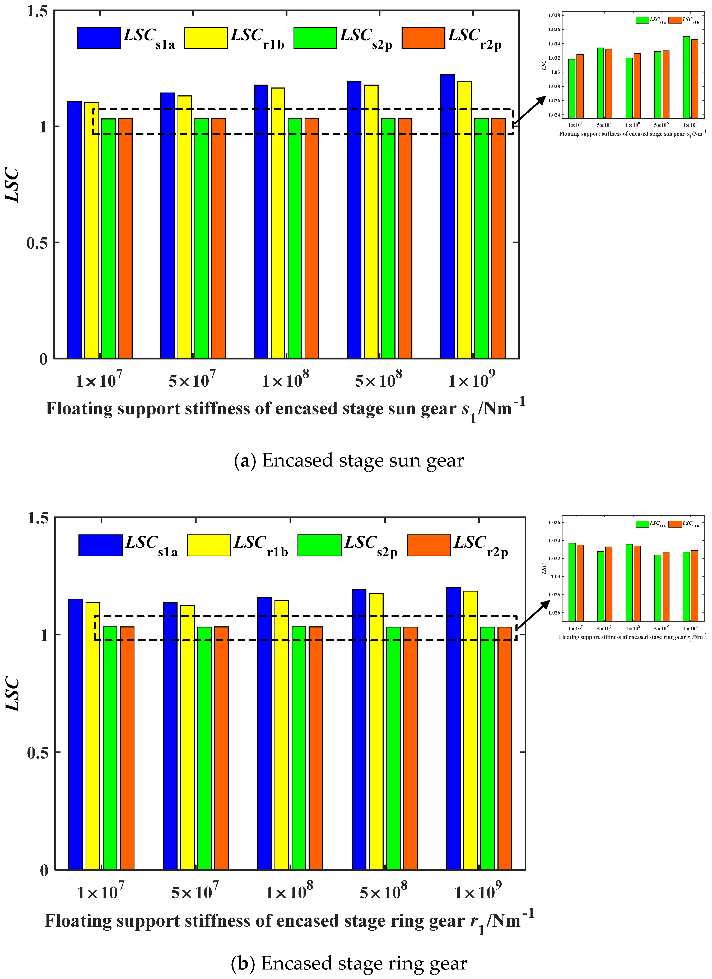
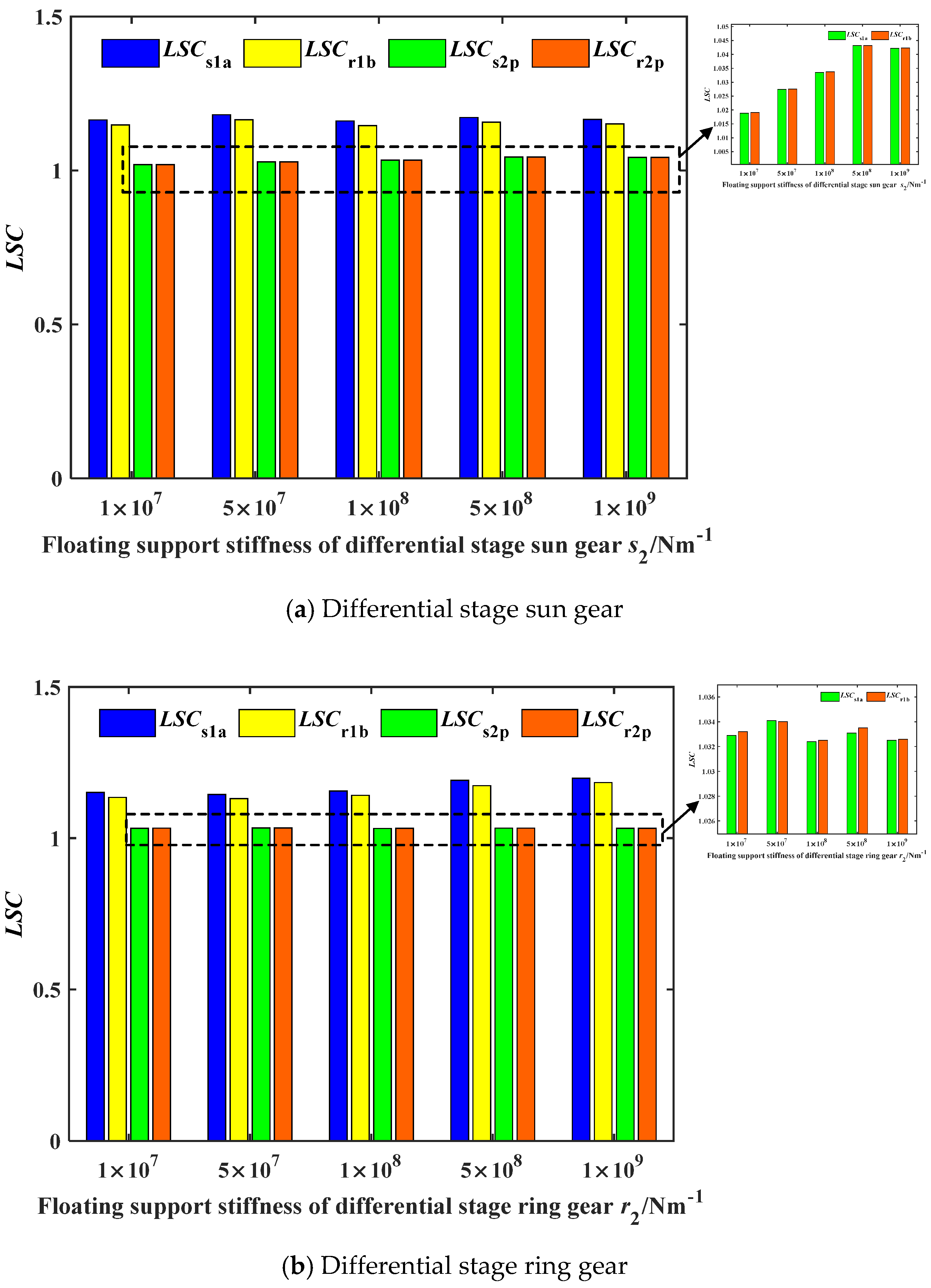
The effect of floating support stiffness on the load-sharing characteristics of the encased differential planetary gear train is studied in this section, in which the floating clearance of the central components are 0 μm, respectively. The statistics of the floating support stiffness on the LSC can refer to Appendix A. In Appendix A, the stiffness orthogonal testing program and results can be found in Table 1, and the analysis results can be found in Table 2. Figure 10 and Figure 11 can be obtained by collating the data in Table 2 into a bar chart.
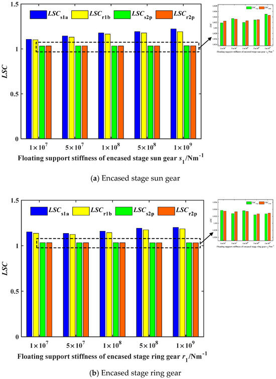
Figure 10.
The effect of floating support stiffness of the encased stage system on the LSC.
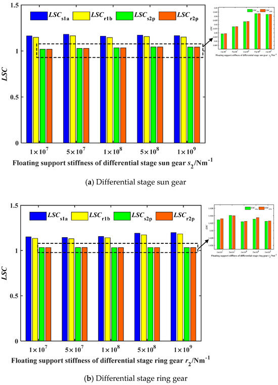
Figure 11.
The effect of floating support stiffness of the differential stage system on the LSC.
Figure 10 and Figure 11 show the effect of the floating support stiffness of the encased stage system and the differential stage system on the LSC, respectively. It can be drawn from Figure 10a that LSCs1a and LSCr1b increase as the floating support stiffness of the encased stage sun gear increases; namely, the load-sharing performance of the encased stage system becomes unacceptable, and LSCs2p and LSCr2p have no obvious changing law. From Figure 10b, it can be seen that with the increase in the floating support stiffness of the inner ring gear in the encased stage, LSCs1a and LSCr1b both show a trend of decreasing first and then increasing, and the load-sharing coefficient is the lowest when kr1 = 5 × 10⁷ N/m, and the variations in LSCs2p and LSCr2p are irregular. Comparing the value of R, it can be found that the floating support stiffness of the sun gear has a greater influence on the load-sharing performance of the system under the encased stage system.
From Figure 11a, it can be found that with the increase in the floating support stiffness of the differential stage sun gear, LSCs1a and LSCr1b show fluctuation changes with no obvious changing law. LSCs2p and LSCr2p show an increasing trend as a whole, but the change amplitude is small; when ks2 = 1 × 10⁹ N/m, the load-sharing coefficient of the differential stage shows a slight downward trend, which might result from the influence of the random error. It can be seen from Figure 11b that the effect of the floating support stiffness of the differential stage inner ring gear on the LSC of the system is similar to that of the encased stage inner ring gear, because of the dual inner ring gear structure. In addition, it should be mentioned that the load-sharing performance of the differential stage system is better than that of the encased stage and therefore less affected by changing of the floating support stiffness.
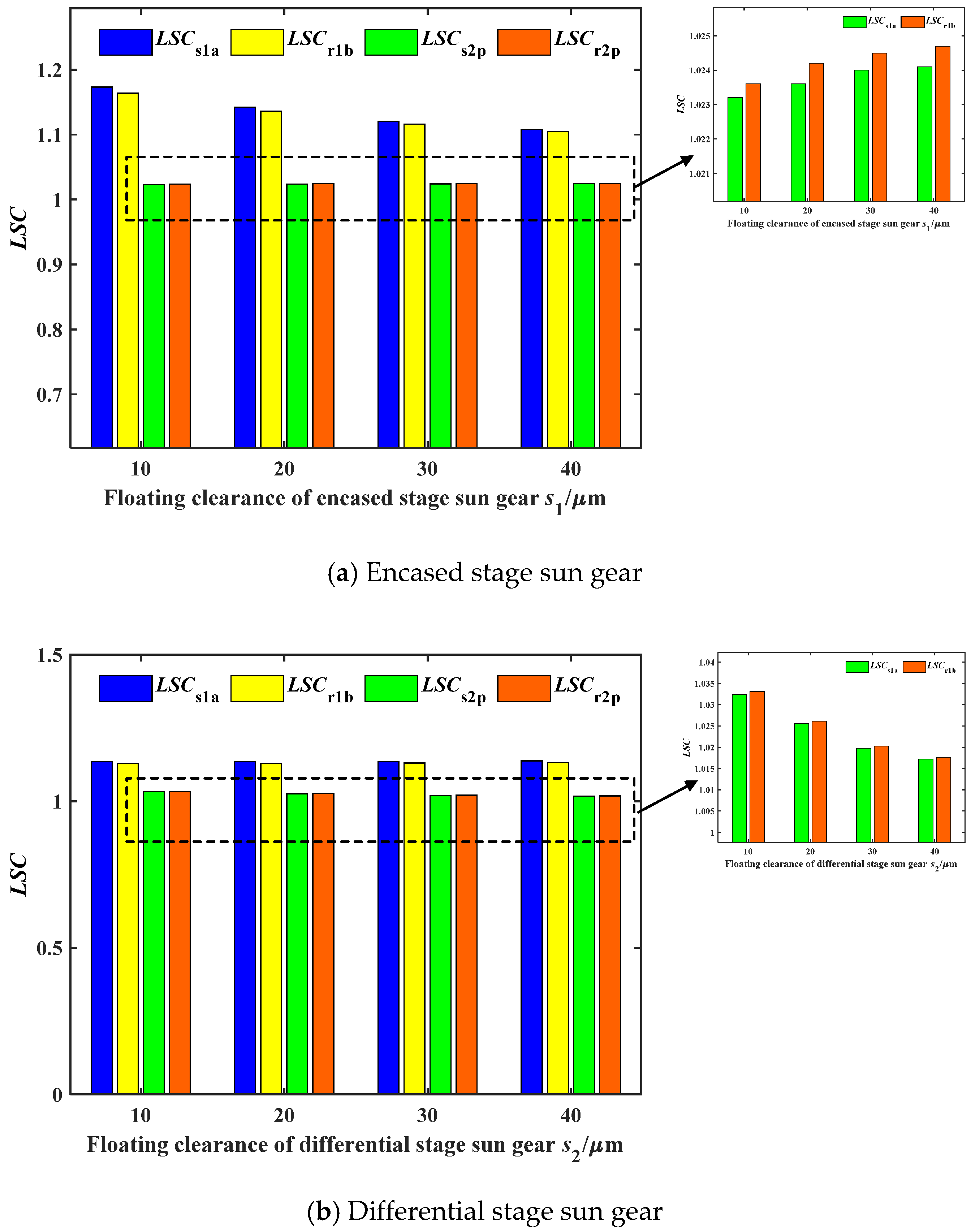
4.6. The Effect of Floating Clearance of the Sun Gear on the Load-Sharing Performance of the EDPGS
The influence of floating clearance of sun gear on the load-sharing characteristics of the EDPGS is studied in this section, in which the floating support stiffness of the central components is 3.5 × 10⁸ N/m, respectively. The statistics of the floating clearance on the LSC can refer to Table A3 and Table A4 in Appendix A. Figure 12 can be obtained by collating the data in Table 4 into a bar chart.
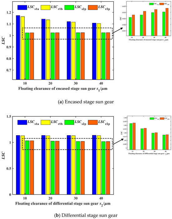
Figure 12.
The effect of floating clearance of the sun gear of the differential stage system on the LSC.
Figure 12 show the effect of floating clearance of the sun gear of the differential stage system on the LSC. It can be concluded from Figure 12a that LSCs1a and LSCr1b both show a decreasing trend as the floating clearance of the encased stage sun gear increases, that is, the load-sharing performance of the encased stage system is improving. Conversely, LSCs2p and LSCr2p are increasing. This is because with the increase in the floating clearance of the encased stage sun gear, the sun gear s1 can adjust the displacement to improve the load-sharing performance of the encased stage system adaptively, but the sun gear s2 is affected by the displacement of the sun gear s1, which aggravates the vibration of the sun gear s2; hence, the load-sharing performance of the differential stage system becomes bad. It can be drawn from Figure 12b that increasing the floating clearance of the sun gear of the differential stage system enhances the load-sharing performance of the differential stage system, while the improvement is not as good as that of the encased stage. Simultaneously, the load-sharing coefficient of encased stage system shows an increasing trend. It should be noted that the increase in the floating clearance of the sun gear in a single stage system will improve the load-sharing performance of the system of that stage, while the load-sharing performance of the other stage system becomes bad.
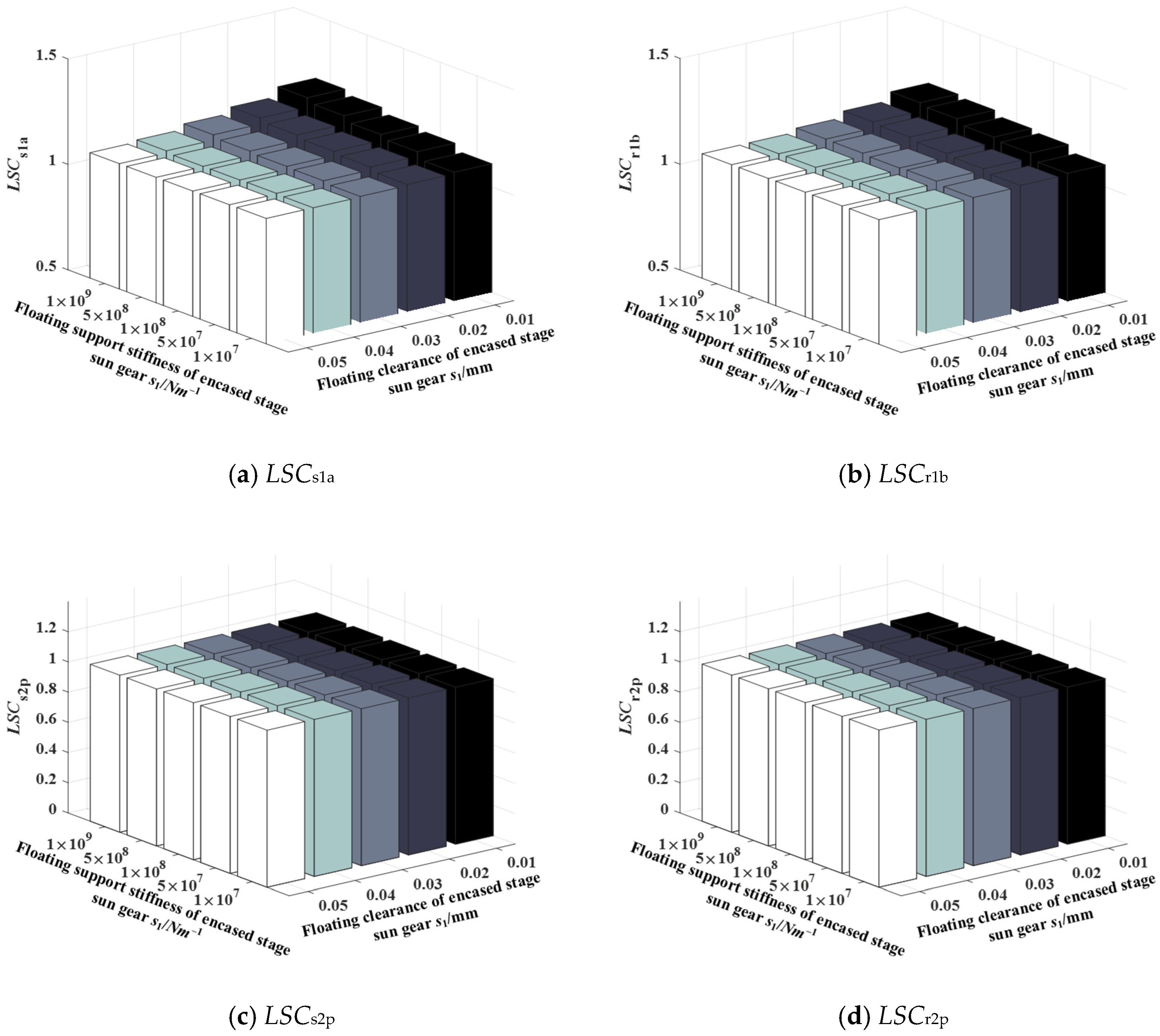
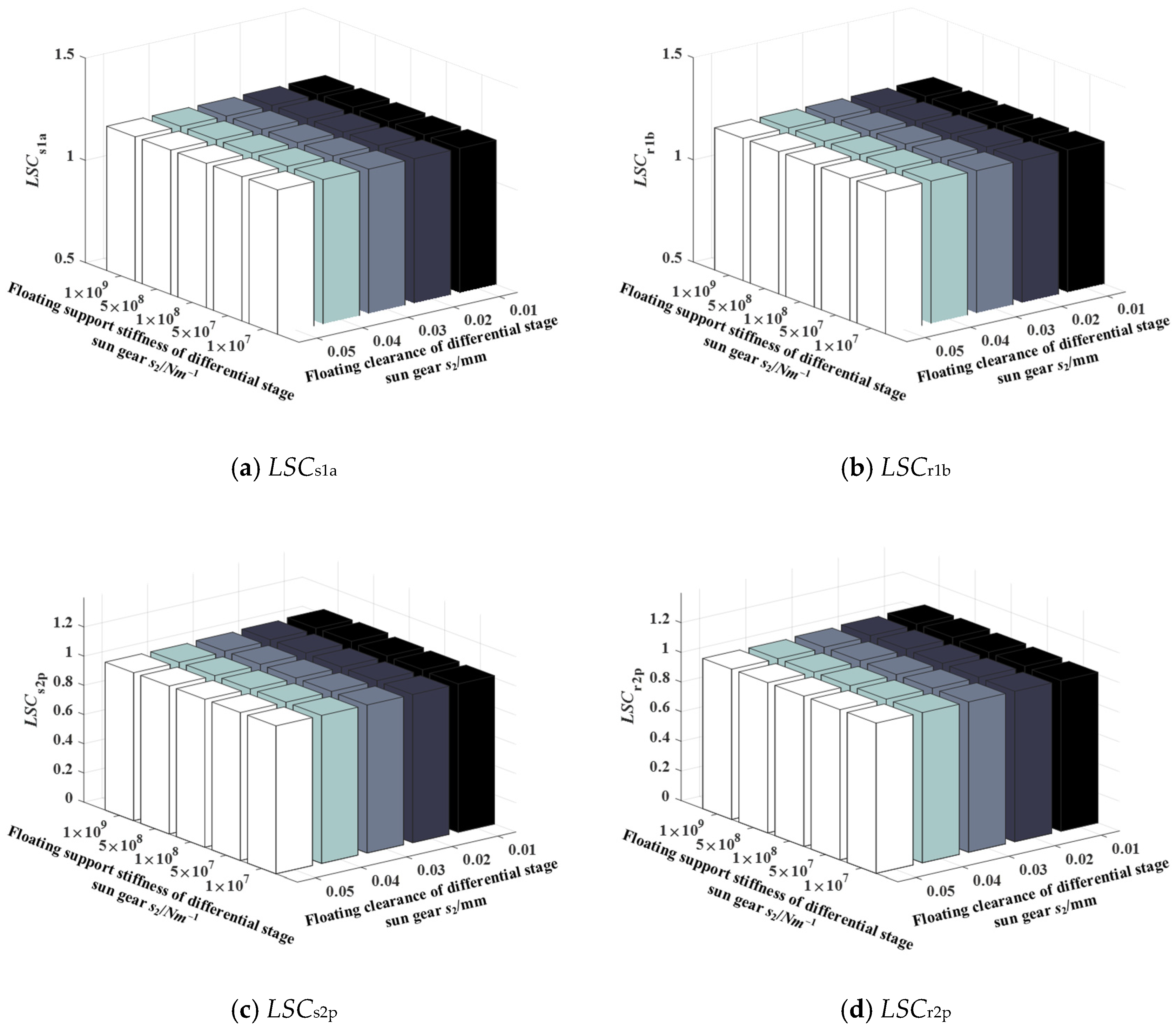
4.7. The Coupling Effect of Floating Sun Gear Parameter on the Load-Sharing Performance of the EDPGS
The coupling effect of floating support stiffness and floating clearance of the sun gear of the encased stage and differential stage on the load-sharing performance of the system is studied in this section, in which the floating support stiffness of the ring gear is 3.5 × 10⁸ N/m, and the floating clearance is 0 μm. Figure 13 show the coupling effect of the floating support stiffness and floating clearance of the encased stage sun gear s1 on the LSCs1a, LSCr1b, LSCs2p, and LSCr2p of the system, respectively. The following two rules can be summarized. First, when the floating clearance of the encased stage sun gear s1 is smaller, the more obvious the influence of the floating support stiffness on the load-sharing coefficient of the system, and the load-sharing coefficient increases with the increase in floating support stiffness. Second, the greater the floating support stiffness of the encased stage sun gear s1, the more obvious the influence of the floating clearance on the load-sharing coefficient of the system, and the load-sharing coefficient decreases with the increase in the floating clearance. Figure 14 shows the coupling effect of the floating support stiffness and floating clearance of the differential stage sun gear s2 on the LSCs1a, LSCr1b, LSCs2p, and LSCr2p of the system, respectively. It can be found that the influence of the floating parameters of the differential stage sun gear on the load-sharing performance of the system is much less obvious than that of the encased stage system.
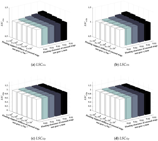
Figure 13.
The coupling effect of floating support stiffness and clearance of the encased stage sun gear on the LSC.
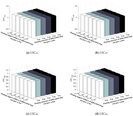
Figure 14.
The coupling effect of floating support stiffness and clearance of the differential stage sun gear on the LSC.
5. Conclusions
In order to investigate the impact of floating support parameters on the dynamic load-sharing behavior of the EDPGS under random error conditions, the dynamic model of the system with floating support parameters is established with the consideration of the influence of time-varying mesh stiffness, and manufacture error and installation error based on the Monte Carlo method and orthogonal experimental design method. The floating support stiffness and floating clearance on the load-sharing performance of the EDPGS were studied, and the following conclusions were obtained:
- (a)
- The probability distribution, expectation, and variance under the sample number with 100, 300, and 500 were compared. When the sample number N = 100, the probability distribution significantly deviated from the fitted Gaussian distribution, and the fitting degree improved at N = 300 and 500. However, the expectation and variance were less affected by the sample number.
- (b)
- The load-sharing coefficient of the encased stage system increases with the increase in the floating support stiffness, and the load-sharing coefficient of the differential stage system increases with the increase in the floating support stiffness of s2.
- (c)
- The load-sharing coefficient of the encased stage system decreased with the increase in the floating clearance of s1. In contrast, the load-sharing coefficient of the differential stage system increased with the increase in the floating clearance of s1 and decreased with the increase in the floating clearance of s2.
- (d)
- The impact of floating support stiffness on load-sharing performance was more pronounced when the floating clearance of s1 was smaller, leading to an increase in the load-sharing coefficient as the floating support stiffness increased. Conversely, a higher floating support stiffness of s1 amplified the influence of floating clearance on load-sharing performance, causing the load-sharing coefficient to decrease with the increase in the floating clearance.
In summary, this study provides valuable insights into the dynamic load-sharing behavior of the EDPGS under various floating support parameters. The findings contribute to a better understanding of gear system performance and can guide the optimization of such systems for practical applications.
Author Contributions
Conceptualization, R.Z.; methodology, X.C.; formal analysis, X.C.; investigation, X.C.; writing—original draft preparation, X.C.; writing—review and editing, R.Z.; supervision, X.C.; project administration, R.Z. All authors have read and agreed to the published version of the manuscript.
Funding
This work is supported by the National Natural Science Foundation of China (Grant No. 52275061) and the national defense technology basic research project of China (JSZL2022110A074).
Data Availability Statement
The datasets generated during and/or analyzed during the current study are available from the corresponding author on reasonable request.
Conflicts of Interest
The authors declared no potential conflicts of interest with respect to the research, authorship, and publication of this paper.
Appendix A
Table A1.
Stiffness orthogonal testing program and results.
Table A1.
Stiffness orthogonal testing program and results.
| Number | ks1 (N/m) | ks2 (N/m) | kr1 (N/m) | kr2 (N/m) | LSCs1a | LSCr1b | LSCs2p | LSCr2p |
|---|---|---|---|---|---|---|---|---|
| 1 | 1 × 10⁷ | 1 × 10⁷ | 1 × 10⁷ | 1 × 10⁷ | 1.0669 | 1.0590 | 1.0186 | 1.0192 |
| 2 | 1 × 10⁷ | 5 × 10⁷ | 1 × 10⁸ | 5 × 10⁸ | 1.1146 | 1.1085 | 1.0271 | 1.0276 |
| 3 | 1 × 10⁷ | 1 × 10⁸ | 1 × 10⁹ | 5 × 10⁷ | 1.1163 | 1.1152 | 1.0319 | 1.0328 |
| 4 | 1 × 10⁷ | 5 × 10⁸ | 5 × 10⁷ | 1 × 10⁹ | 1.1183 | 1.1154 | 1.0412 | 1.0420 |
| 5 | 1 × 10⁷ | 1 × 10⁹ | 5 × 10⁸ | 1 × 10⁸ | 1.1149 | 1.1099 | 1.0402 | 1.0409 |
| 6 | 5 × 10⁷ | 1 × 10⁷ | 1 × 10⁹ | 5 × 10⁸ | 1.1812 | 1.1638 | 1.0205 | 1.0204 |
| 7 | 5 × 10⁷ | 5 × 10⁷ | 5 × 10⁷ | 5 × 10⁷ | 1.1104 | 1.1000 | 1.0277 | 1.0281 |
| 8 | 5 × 10⁷ | 1 × 10⁸ | 5 × 10⁸ | 1 × 10⁹ | 1.1782 | 1.1632 | 1.0336 | 1.0335 |
| 9 | 5 × 10⁷ | 5 × 10⁸ | 1 × 10⁷ | 1 × 10⁸ | 1.1240 | 1.1131 | 1.0436 | 1.0425 |
| 10 | 5 × 10⁷ | 1 × 10⁹ | 1 × 10⁸ | 1 × 10⁷ | 1.1249 | 1.1128 | 1.0414 | 1.0413 |
| 11 | 1 × 10⁸ | 1 × 10⁷ | 5 × 10⁸ | 5 × 10⁷ | 1.1794 | 1.1665 | 1.0179 | 1.0182 |
| 12 | 1 × 10⁸ | 5 × 10⁷ | 1 × 10⁷ | 1 × 10⁹ | 1.1877 | 1.1769 | 1.0266 | 1.0269 |
| 13 | 1 × 10⁸ | 1 × 10⁸ | 1 × 10⁸ | 1 × 10⁸ | 1.1451 | 1.1315 | 1.0327 | 1.0333 |
| 14 | 1 × 10⁸ | 5 × 10⁸ | 1 × 10⁹ | 1 × 10⁷ | 1.1968 | 1.1828 | 1.0413 | 1.0422 |
| 15 | 1 × 10⁸ | 1 × 10⁹ | 5 × 10⁷ | 5 × 10⁸ | 1.1779 | 1.1658 | 1.0417 | 1.0423 |
| 16 | 5 × 10⁸ | 1 × 10⁷ | 1 × 10⁸ | 1 × 10⁹ | 1.2332 | 1.2174 | 1.0180 | 1.0178 |
| 17 | 5 × 10⁸ | 5 × 10⁷ | 1 × 10⁹ | 1 × 10⁸ | 1.2379 | 1.2211 | 1.0265 | 1.0263 |
| 18 | 5 × 10⁸ | 1 × 10⁸ | 5 × 10⁷ | 1 × 10⁷ | 1.1152 | 1.1054 | 1.0341 | 1.0345 |
| 19 | 5 × 10⁸ | 5 × 10⁸ | 5 × 10⁸ | 5 × 10⁸ | 1.2377 | 1.2192 | 1.0413 | 1.0422 |
| 20 | 5 × 10⁸ | 1 × 10⁹ | 1 × 10⁷ | 5 × 10⁷ | 1.1350 | 1.1218 | 1.0446 | 1.0441 |
| 21 | 1 × 10⁹ | 1 × 10⁷ | 5 × 10⁷ | 1 × 10⁸ | 1.1572 | 1.1317 | 1.0191 | 1.0197 |
| 22 | 1 × 10⁹ | 5 × 10⁷ | 5 × 10⁸ | 1 × 10⁷ | 1.2534 | 1.2142 | 1.0289 | 1.0287 |
| 23 | 1 × 10⁹ | 1 × 10⁸ | 1 × 10⁷ | 5 × 10⁸ | 1.2465 | 1.2116 | 1.0351 | 1.0348 |
| 24 | 1 × 10⁹ | 5 × 10⁸ | 1 × 10⁸ | 5 × 10⁷ | 1.1808 | 1.1521 | 1.0486 | 1.0470 |
| 25 | 1 × 10⁹ | 1 × 10⁹ | 1 × 10⁹ | 1 × 10⁹ | 1.2743 | 1.2462 | 1.0431 | 1.0429 |
Table A2.
Results of stiffness orthogonal test analysis.
Table A2.
Results of stiffness orthogonal test analysis.
| ks1 (N/m) | ks2 (N/m) | kr1 (N/m) | kr2 (N/m) | |
|---|---|---|---|---|
| k1 (LSCs1a) | 1.1062 | 1.1636 | 1.1520 | 1.1514 |
| k2 (LSCs1a) | 1.1437 | 1.1808 | 1.1358 | 1.1444 |
| k3 (LSCs1a) | 1.1774 | 1.1603 | 1.1597 | 1.1558 |
| k4 (LSCs1a) | 1.1918 | 1.1715 | 1.1927 | 1.1916 |
| k5 (LSCs1a) | 1.2224 | 1.1654 | 1.2013 | 1.1983 |
| R (LSCs1a) | 0.1162 | 0.0205 | 0.0655 | 0.0539 |
| k1 (LSCr1b) | 1.1016 | 1.1477 | 1.1365 | 1.1348 |
| k2 (LSCr1b) | 1.1306 | 1.1641 | 1.1237 | 1.1311 |
| k3 (LSCr1b) | 1.1647 | 1.1454 | 1.1445 | 1.1415 |
| k4 (LSCr1b) | 1.1770 | 1.1565 | 1.1746 | 1.1738 |
| k5 (LSCr1b) | 1.1912 | 1.1513 | 1.1858 | 1.1838 |
| R (LSCr1b) | 0.0896 | 0.0059 | 0.0621 | 0.0527 |
| k1 (LSCs2p) | 1.0318 | 1.0188 | 1.0337 | 1.0329 |
| k2 (LSCs2p) | 1.0334 | 1.0274 | 1.0328 | 1.0341 |
| k3 (LSCs2p) | 1.0320 | 1.0335 | 1.0336 | 1.0324 |
| k4 (LSCs2p) | 1.0329 | 1.0432 | 1.0324 | 1.0331 |
| k5 (LSCs2p) | 1.0350 | 1.0422 | 1.0327 | 1.0325 |
| R (LSCs2p) | 0.0032 | 0.0244 | 0.0013 | 0.0017 |
| k1 (LSCr2p) | 1.0325 | 1.0191 | 1.0335 | 1.0332 |
| k2 (LSCr2p) | 1.0332 | 1.0275 | 1.0333 | 1.0340 |
| k3 (LSCr2p) | 1.0326 | 1.0338 | 1.0334 | 1.0325 |
| k4 (LSCr2p) | 1.0330 | 1.0432 | 1.0327 | 1.0335 |
| k5 (LSCr2p) | 1.0346 | 1.0423 | 1.0329 | 1.0326 |
| R (LSCr2p) | 0.0021 | 0.0241 | 0.0008 | 0.0015 |
k1, k2, k3, k4, and k5 are the comprehensive averages of the corresponding index values of levels 1, 2, 3, 4, and 5, respectively. R is the difference between the maximum and minimum values in k1, k2, k3, k4, and k5, and the definitions of k1, k2, k3, k4, k5, and R are suitable for Table 4 in the Appendix A.
Table A3.
Clearance orthogonal testing program and results.
Table A3.
Clearance orthogonal testing program and results.
| Number | Rs1 (μm) | Rs2 (μm) | LSCs1a | LSCr1b | LSCs2p | LSCr2p |
|---|---|---|---|---|---|---|
| 1 | 10 | 10 | 1.1747 | 1.1660 | 1.0325 | 1.0330 |
| 2 | 10 | 20 | 1.1714 | 1.1627 | 1.0254 | 1.0260 |
| 3 | 10 | 30 | 1.1710 | 1.1615 | 1.0192 | 1.0196 |
| 4 | 10 | 40 | 1.1747 | 1.1639 | 1.0156 | 1.0159 |
| 5 | 20 | 10 | 1.1420 | 1.1350 | 1.0323 | 1.0330 |
| 6 | 20 | 20 | 1.1417 | 1.1355 | 1.0254 | 1.0260 |
| 7 | 20 | 30 | 1.1414 | 1.1352 | 1.0196 | 1.0200 |
| 8 | 20 | 40 | 1.1438 | 1.1376 | 1.0172 | 1.0176 |
| 9 | 30 | 10 | 1.1186 | 1.1135 | 1.0323 | 1.0331 |
| 10 | 30 | 20 | 1.1205 | 1.1157 | 1.0255 | 1.0260 |
| 11 | 30 | 30 | 1.1199 | 1.1162 | 1.0201 | 1.0205 |
| 12 | 30 | 40 | 1.1213 | 1.1182 | 1.0179 | 1.0184 |
| 13 | 40 | 10 | 1.1044 | 1.0989 | 1.0324 | 1.0331 |
| 14 | 40 | 20 | 1.1080 | 1.1043 | 1.0256 | 1.0262 |
| 15 | 40 | 30 | 1.1084 | 1.1057 | 1.0204 | 1.0209 |
| 16 | 40 | 40 | 1.1097 | 1.1080 | 1.0181 | 1.0186 |
Table A4.
Results of clearance orthogonal test analysis.
Table A4.
Results of clearance orthogonal test analysis.
| Rs1 (μm) | Rs2 (μm) | |
|---|---|---|
| k1 (LSCs1a) | 1.1730 | 1.1349 |
| k2 (LSCs1a) | 1.1422 | 1.1354 |
| k3 (LSCs1a) | 1.1201 | 1.1352 |
| k4 (LSCs1a) | 1.1076 | 1.1374 |
| R (LSCs1a) | 0.0654 | 0.0025 |
| k1 (LSCr1b) | 1.1635 | 1.1284 |
| k2 (LSCr1b) | 1.1358 | 1.1296 |
| k3 (LSCr1b) | 1.1159 | 1.1297 |
| k4 (LSCr1b) | 1.1042 | 1.1319 |
| R (LSCr1b) | 0.0593 | 0.0035 |
| k1 (LSCs2p) | 1.0232 | 1.0324 |
| k2 (LSCs2p) | 1.0236 | 1.0255 |
| k3 (LSCs2p) | 1.0240 | 1.0198 |
| k4 (LSCs2p) | 1.0241 | 1.0172 |
| R (LSCs2p) | 0.0009 | 0.0152 |
| k1 (LSCr2p) | 1.0236 | 1.0331 |
| k2 (LSCr2p) | 1.0242 | 1.0261 |
| k3 (LSCr2p) | 1.0245 | 1.0203 |
| k4 (LSCr2p) | 1.0247 | 1.0176 |
| R (LSCr2p) | 0.0011 | 0.0155 |
References
- Wang, C. The effect of planetary gear/star gear on the transmission efficiency of closed differential double helical gear train. Proc. Inst. Mech. Eng. Part C J. Mech. Eng. Sci. 2020, 234, 4215–4223. [Google Scholar] [CrossRef]
- Kuznetsova, N.A.; Tetyushev, A.A.; Shandybina, I.M. Dynamic Model of Differential Closed Planetary Gearing and the Spectrum of its Eigenfrequencies. Chem. Pet. Eng. 2018, 54, 488–492. [Google Scholar] [CrossRef]
- Zhu, Z.; Zhu, R.; Bao, H.; Jin, G. Analysis of dynamic floating displacement of center gear for encased differential planetary train. J. Cent. South Univ. 2012, 43, 497–504. [Google Scholar]
- Zhu, Z.; Zhu, R. Meshing stiffness variation instabilities in encased differential planetary gear train. J. Mech. Eng. 2016, 52, 25–33. [Google Scholar] [CrossRef]
- Zhu, Z.; Cheng, L.; Xu, R.; Zhu, R. Impacts of Backlash on Nonlinear Dynamic Characteristic of Encased Differential Planetary Gear Train. Shock Vib. 2019, 2019, 9347925. [Google Scholar] [CrossRef]
- Zhang, D.; Zhu, R.; Li, M.; Tan, W.; Li, P. Meshing Stiffness Parametric Vibration of Coaxial Contrarotating Encased Differential Gear Train. Math. Probl. Eng. 2021, 2021, 8950945. [Google Scholar] [CrossRef]
- Zhang, D.; Zhu, R.; Fu, B.; Tan, W. Mesh Phase Analysis of Encased Differential Gear Train for Coaxial Twin-Rotor Helicopter. Math. Probl. Eng. 2019, 2019, 8421201. [Google Scholar] [CrossRef]
- Zhang, D.; Zhu, R.; Fu, B.; Tan, W. Modal Properties of Contra-rotating Encased Differential Gear Train Used in Coaxial Helicopter. J. Vib. Eng. Technol. 2020, 8, 799–814. [Google Scholar] [CrossRef]
- Yang, J.; Yue, Y.; Zhu, R.; Chen, W.; Li, M. Dynamic Characteristics of Encased Differential Gear Train with Journal Bearing. Math. Probl. Eng. 2020, 2020, 2436191. [Google Scholar] [CrossRef]
- Yang, J.; Lin, T.; Jiang, L.; Xiang, Y.; Wei, J. Load sharing performance analysis of planetary gear system considering the coupling effects of gear pair and journal bearing. J. Vib. Control 2023, 10775463231177775. [Google Scholar] [CrossRef]
- Ryali, L.; Talbot, D. A dynamic gear load distribution model for epicyclic gear sets with a structurally compliant planet carrier. Mech. Mach. Theory 2023, 181, 105225. [Google Scholar] [CrossRef]
- Che, X.; Zhu, R. Dynamic behavior analysis of planetary gear transmission system with bolt constraint of the flexible ring gear. Meccanica 2023, 58, 1173–1204. [Google Scholar] [CrossRef]
- Zhang, C.; Wei, J.; Niu, R.; Hou, S.; Zhang, S. Similarity and experimental prediction on load sharing performance of planetary gear transmission system. Mech. Mach. Theory 2023, 180, 105163. [Google Scholar] [CrossRef]
- Yoo, H.-G.; Chung, W.-J.; Kim, B.-S.; Park, Y.-J.; Kim, S.-C.; Lee, G.-H. Application of flexible pin for planetary gear set of wind turbine gearbox. Sci. Rep. 2022, 12, 1713. [Google Scholar] [CrossRef] [PubMed]
- Xu, Z.; Yu, W.; Shao, Y.; Yang, X.; Nie, C.; Peng, D. Dynamic modeling of the planetary gear set considering the effects of positioning errors on the mesh position and the corner contact. Nonlinear Dyn. 2022, 109, 1551–1569. [Google Scholar] [CrossRef]
- Zhang, H.; Shang, H.; Yang, C. Influence of floating support on the dynamic characteristics of compound planetary gear set. J. Vibroengineering 2022, 24, 272–289. [Google Scholar] [CrossRef]
- Fang, Y.; Zuo, M.J.; Li, Y. Investigation of Gear Dynamic Characteristics under Stochastic External Excitations. In Proceedings of the 2019 International Conference on Advances in Materials, Mechanical and Manufacturing (AMMM 2019), Beijing, China, 22–24 March 2019; IOP Publishing: Bristol, UK, 2019; Volume 576. [Google Scholar] [CrossRef]
- Diez-Ibarbia, A.; Sanchez-Espiga, J.; Fernandez-Del-Rincon, A.; Calvo-Irisarri, J.; Iglesias, M.; Viadero, F. Probabilistic analysis of the mesh load factor in wind-turbine planetary transmissions: Tooth thickness errors. Mech. Mach. Theory 2023, 185, 105341. [Google Scholar] [CrossRef]
- Jun, Z.; Wei-Min, T.; Qin, C.; Tao, C. Reliability sensitivity analysis of tooth modification on dynamic transmission error of helical planetary gears. Proc. Inst. Mech. Eng. Part C J. Mech. Eng. Sci. 2020, 234, 3903–3918. [Google Scholar] [CrossRef]
- Hajnayeb, A.; Sun, Q. Study of gear pair vibration caused by random manufacturing errors. Arch. Appl. Mech. 2022, 92, 1451–1463. [Google Scholar] [CrossRef]
- Jin, G.H.; Xu, X.T.; Zhu, R.P. Analysis of load sharing mechanism and parameter matching of gear split torque drive system. J. Aerosp. Power 2020, 35, 71–80. [Google Scholar]
- Hu, C.; Geng, G.; Spanos, P.D. Stochastic dynamic load-sharing analysis of the closed differential planetary transmission gear system by the Monte Carlo method. Mech. Mach. Theory 2021, 165, 104420. [Google Scholar] [CrossRef]
- ISO 6336-1; Calculation of Load Capacity of Spur and Helical Gears Part 1: Basie Principles, Introduction and General Influence Factors. ISO: Geneva, Switzerland, 2006.
- Shuai, M.; Ting, Z.; Guo-Guang, J.; Xiao-lin, C.; Han-Jun, G. Analytical investigation on load sharing characteristics of herringbone planetary gear train with flexible support and floating sun gear. Mech. Mach. Theory 2020, 144, 103670. [Google Scholar] [CrossRef]
- Wu, H. Research on the Dynamic Characteristics of Rolling Element Bearings and the Dynamic Model of Bearing Rotor System. Ph.D. Dissertation, East China University of Science and Technology, Shanghai, China, 2011. (In Chinese). [Google Scholar]
- Dong, H.; Zhang, H.Q.; Zhao, X.L.; Duan, L.L. Study on dynamic load-sharing characteristics of face gear dual-power split transmission system with backlash, support and spline clearance. Mech. Sci. 2021, 12, 573–587. [Google Scholar] [CrossRef]
- Zhanfei, S.; Jianxing, Z.; Xiangfeng, Z.; Hong, J.; Yuan, S.; Xu, G. Study on dynamic characteristics of wind turbine planetary gear transmission system considering tooth shape error. Acta Energiae Solaris Sin. 2017, 43, 315. [Google Scholar]
- Li, S.; Wu, S.; Wang, X. Analysis of the Dynamic Load Sharing Characteristic of Two-stage Planetary Transmission. J. Mech. Transm. 2016, 40, 11–16. [Google Scholar]
- Li, X. Nonlinear Dynamic Modeling and Comprehensive Performance Optimization Design for NW Wind Turbine Gearbox. Ph.D. Dissertation, Dalian University of Technology, Dalian, China, 2018. (In Chinese). [Google Scholar]
- Guan, P.; DeSmidt, H.A. Passive suppression of planetary gear transmission vibration via discrete boundary struts. In Proceedings of the AHS 72nd Annual Forum, West Palm Beach, FL, USA, 17–19 May 2016. [Google Scholar]
- Wang, C.L.; Wei, J.; Wu, Z.H.; Lu, L.; Gao, H. Load sharing performance of herringbone planetary gear system with flexible pin. Int. J. Precis. Eng. Manuf. 2019, 20, 2155–2169. [Google Scholar] [CrossRef]


Disclaimer/Publisher’s Note: The statements, opinions and data contained in all publications are solely those of the individual author(s) and contributor(s) and not of MDPI and/or the editor(s). MDPI and/or the editor(s) disclaim responsibility for any injury to people or property resulting from any ideas, methods, instructions or products referred to in the content. |
© 2024 by the authors. Licensee MDPI, Basel, Switzerland. This article is an open access article distributed under the terms and conditions of the Creative Commons Attribution (CC BY) license (https://creativecommons.org/licenses/by/4.0/).