Abstract
This paper analyzes traditional vibration suppression methods in order to solve the vibration problem caused by the stiffness of flexible industrial robots. The principle of closed-loop control dynamic feedforward vibration suppression is described as the main method for solving robot vibration suppression. This paper proposes a method for time-lag filtering based on T-trajectory interpolation, which combines the T-planning curve and the time-lag filtering method. The method’s basic principle is to dynamically adjust the trajectory output through the algorithm, which effectively suppresses the amplitude of the harmonic components of a specific frequency band to improve the vibration response of industrial robot systems. This experiment compared traditional vibration suppression methods with the time-lag filtering method based on T-trajectory interpolation. A straight-line method was proposed to measure the degree of vibration. The results demonstrate that the time-lag filtering method based on T-trajectory interpolation is highly effective in reducing the vibration of industrial robots. This makes it an excellent option for scenarios that demand real-time response and high-precision control, ultimately enhancing the efficiency and stability of robots in performing their tasks.
1. Introduction
Industrial robots are becoming increasingly important in manufacturing due to the rapid development of science and technology and the rise of industrial automation. They enhance productivity, lower costs, and create a safer working environment for humans by performing tasks with efficient and precise movements [1,2,3]. However, the widespread use of robots in industry has brought the vibration problem caused by robots during operation to the forefront. This problem has become one of the most important factors affecting the performance and work stability of robots. The vibration of industrial robots primarily results from their complex mechanical structure and the instability of the motion process. This is especially true when harmonic reducers are included, which inevitably leads to increased joint flexibility and poor rigidity. Vibrations not only affect the working accuracy and stability of the robot, but can also lead to mechanical wear, equipment failure, and reduced production quality. Therefore, vibration suppression is a significant concern in the field of industrial robotics research [4].
The vibration suppression control of industrial robots can improve their accuracy, performance, and mechanical durability. The goal of vibration suppression is to reduce or eliminate robot vibration through advanced control strategies, materials, and design methods, thereby improving motion accuracy and stability. Relevant vibration suppression methods have been explored in previous work. The literature [5] discusses the problem of vibration suppression in multi-degree-of-freedom industrial robots and proposes new methods to improve existing input-shaping techniques. The proposed techniques include an optimal S-curve trajectory, a robust zero-vibration shaper, and a dynamic zero-vibration shaper. Additionally, a structural vibration avoidance technique based on a combination of input shaping and learning-based structural dynamics modeling is proposed in the literature [6]. The effectiveness of this method was experimentally verified on a Staubli RX90CR robot (Staubli, Pfäffikon, Switzerland), where the residual vibration of the robot during heavy motions was reduced by more than 85%. The literature [7] presents an enhanced trajectory planning method to reduce vibration in collaborative robots. The authors established a rigid–flexible coupled dynamics model of the robot using the finite element and Lagrangian methods and derived the vibration equations. The trajectory planning method optimizes the excitation force to reduce the vibration of the collaborative robot and ensure the accuracy of the robot’s end position. The literature [8] proposes a vibration suppression algorithm for an industrial robot joint servo system based on a kinematic model and internal mode control. This algorithm can suppress vibrations of the joint servo system without requiring additional sensors or complex control algorithms. Anti-vibration filters are added between the position and velocity loops. These methods have the following problems: the methods have high computational overhead and cannot always be used in real-time scenarios; and vibration suppression is implemented in the actuators of the control system, but this may lead to changes in the robot trajectory. With regard to the matter of industrial robot vibration, there are a number of commonly utilized algorithms, including trajectory planning, dynamic feedforward, and deep learning-based vibration suppression. While these algorithms have made progress in addressing the issue, it is possible that they may not entirely fulfill the engineering requirements. The literature [9] proposes a new method for reducing residual vibrations in underactuated and uncertain flexible systems through motion planning. The method proposed in this study utilizes both input shaping and modifications in the mechanical characteristics of the system concurrently, thereby enhancing robustness against uncertain parameters. By integrating these techniques, the system’s ability to suppress residual vibrations is significantly improved, leading to more stable and reliable operation.
This paper introduces the basic principles of industrial robot vibration, including the source of vibration, propagation mode, and the impact on robot performance. It is important to note that due to the great variability of the mechanical structure of robots, this paper does not optimize or analyze the robot’s ontological structure. Two methods are proposed for robot vibration suppression: closed-loop control-based dynamic feedforward and T-trajectory interpolation-based time-lag filtering. Both methods have their own advantages and can be used depending on the specific requirements of the application. The T-trajectory interpolation-based method can dynamically adjust the trajectory output, suppressing the amplitude of harmonic components in a specific frequency band to a great extent. This paper analyzes the advantages and disadvantages of traditional vibration suppression methods and T-trajectory interpolation-based time-lag filtering techniques. The method proposed in this paper is verified for correctness.
Finally, this paper discusses future trends in vibration suppression for industrial robots and provides suggestions for promoting research and application in this field. The continuous innovation of vibration suppression technology may also provide useful insights for vibration problems in other fields and promote cross-field application and development of science and technology.
The main contributions of this paper are as follows:
- (a)
- This paper analyzes the methods of robot vibration suppression and proposes a new vibration suppression system for the SIASUN 20 kg flexible robot (SIASUN, Shenyang, China).
- (b)
- The principle of closed-loop control dynamic feedforward vibration suppression is described, which has become the main method for solving robot vibration suppression.
- (c)
- This study proposes a vibration suppression method that incorporates time-lag filtering at the robot controller layer, which can ensure consistency in the robot’s motion at each joint.
- (d)
- This article combines the time delay filtering method with the T-programming method to address the flexible vibration of robotic arms.
- (e)
- This article proposes a straight-line method to measure the degree of vibration.
- (f)
- This article compares traditional methods of vibration suppression with the proposed method through experiments. The proposed method has been applied to the SIASUN 20 kg robot and has demonstrated strong real-time performance, making it suitable for practical engineering.
2. Overview of the Vibration Problem System
2.1. Vibration Problems
This paper utilizes the vibration test object system depicted in Figure 1 to study industrial robot vibration, which is caused by periodic and regular oscillation or vibration during the robot’s motion or static process due to changes in the rigidity of the mechanical structure, loosening of the joint drive system, and variations in the load [10,11,12,13,14]. Vibration sources often arise from changes in the mechanical structure’s rigidity, which can result in deformation and vibration during the robot’s motion and under load [15,16,17,18]. Furthermore, load variations can also contribute to vibration. During operation, it is possible that fluctuations in load may cause instability in system dynamics, which could result in vibration.
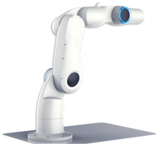
Figure 1.
Experimental object system for industrial robot vibration.
Mechanical Resonance: Similar to any physical object, robots exhibit natural frequencies at which they are more susceptible to resonance. If the operational frequency of a robot coincides with its mechanical resonance frequency, it can result in excessive vibration. This phenomenon can be alleviated through the implementation of damping techniques or modification of the robot’s design.
High-Speed Motion: When robots engage in high-speed motion or rapid acceleration, they can experience vibrations resulting from abrupt changes in their movement. These vibrations may be particularly noticeable in lightweight robots or those equipped with flexible structures.
The Effects of Vibration on Robot Performance: Vibration can cause positional deviations of the robot’s end-effector, which negatively affects its motion accuracy. Additionally, vibration can negatively impact the stability of the robot, particularly at high speeds or under high load conditions. Furthermore, vibration may lead to increased wear and tear of mechanical components, ultimately reducing the robot’s lifespan. To effectively address the vibration problem of industrial robots, it is necessary to comprehensively consider the robot’s structural design, control system, sensor technology, and vibration suppression strategy.
2.2. Traditional Vibration Suppression Methods
Traditional methods for suppressing vibration in industrial robots include mechanical design, control systems, and material selection [18,19,20,21]. These techniques aim to mitigate or eliminate vibration. Below are some common methods used for traditional vibration suppression:
- Optimization of mechanical structure
Rigid Design: By increasing the rigidity of the robot structure and reducing the deformation of the structure, vibration can be reduced.
Damping Structure Design: To reduce vibration transmission, damping materials or shock absorbers can be used to transfer vibration energy to the damping materials.
(This article does not optimize the mechanical structure)
- 2.
- Dynamics modeling and control
Model Predictive Control: A system dynamics model is used to predict and suppress vibrations by optimizing control inputs for future states.
Adaptive Control: The adaptive control algorithm adjusts control parameters in real time to suit different working conditions based on the system’s dynamic characteristics.
Dynamic Feedforward: Dynamic feedforward is utilized to actively control the behavior of a system by incorporating information from the system dynamics model into the control system to predict future behavior and compensate for it. The dynamic equations describe how the system’s components interact with and respond to external forces. Constructing precise dynamic models can improve our understanding of the system’s behavior and our ability to predict its future state.
- 3.
- Closed-loop control vibration suppression technology
Acceleration Sensor: This sensor is used to measure the acceleration of the robot and provide real-time information on vibration.
PID Control: Proportional-Integral-Derivative (PID) controllers are commonly utilized in closed-loop control systems to mitigate vibration by adjusting real-time feedback signals of position, velocity, or acceleration.
Model Predictive Control: MPC is a control strategy that utilizes a robot’s dynamics model to predict and optimize control inputs in real time, allowing for adaptation to varying vibration conditions.
Adaptive Control: The control parameters are adaptively adjusted based on real-time vibration feedback information to handle various working environments and load conditions.
- 4.
- Active vibration control
Active Vibration Suppression System: Introduces an active vibration suppression device that can counteract robot vibration by monitoring and feeding back vibration signals in real time to generate anti-vibration forces.
These traditional methods for suppressing vibrations can often be combined to select the most appropriate solution for a specific industrial robot application and working environment. However, these methods may face challenges such as accuracy, real-time performance, and cost. Therefore, new research and innovations are constantly emerging in the field of vibration suppression.
- 5.
- Predictive control
Predictive control is an advanced control method used to solve system vibration problems. It monitors the system status in real time and predicts future vibrations to take control measures to suppress them. This method usually involves using sensors to collect system data, and then using models to predict future vibration behavior, allowing for control measures to be taken in advance to suppress vibration occurrence. Predictive control is a widely used technique in engineering, particularly in areas such as vibration suppression, wind power generation, and robot control. It involves predicting the behavior of a system and implementing control strategies in a timely manner to effectively reduce the impact of system vibration on performance and stability.
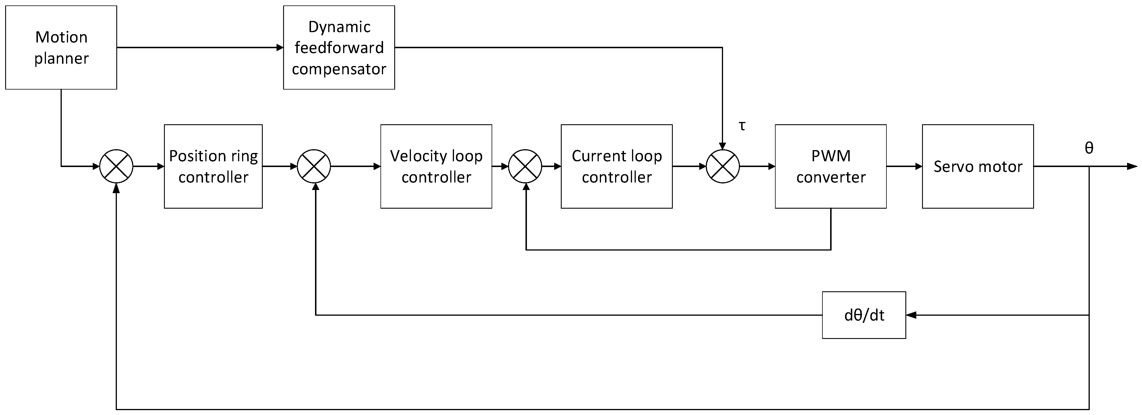
3. Vibration Suppression Method Based on Dynamic Feedforward
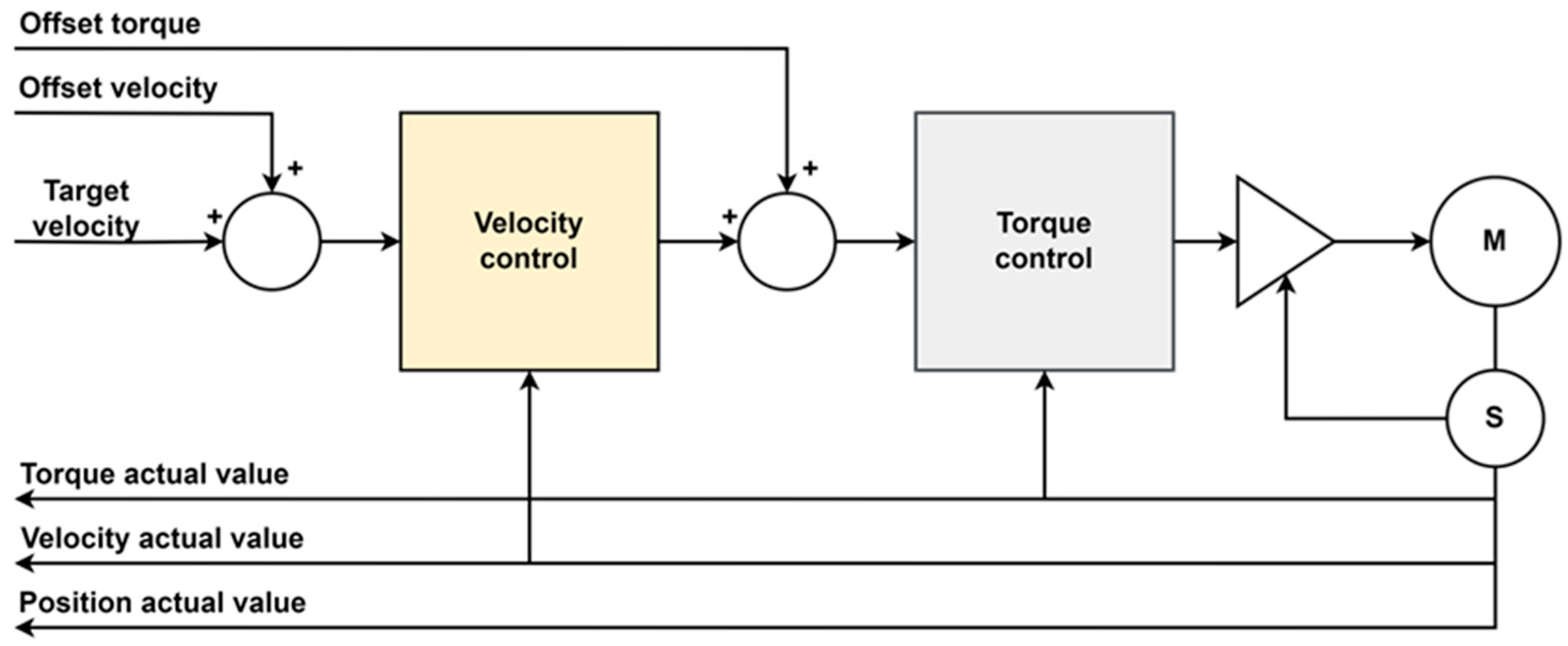
Although the closed-loop control algorithm is complex, it still provides better vibration suppression and control accuracy than open-loop control [21,22,23,24,25]. Figure 2 shows the vibration control system structure of the industrial robot discussed in this paper. The closed-loop control system also employs filtering optimization of the motion trajectory and feedforward compensation to effectively suppress vibrations. This paper combines closed-loop control with dynamic feedforward compensation to suppress robot vibrations. The use of dynamic feedforward significantly improves the robot’s motion performance. The proposed method addresses these issues and improves the robot’s overall performance. In industrial settings, robots may experience motion errors and vibrations due to inertia, friction, and other dynamic effects when performing high-speed motion, complex path tracking, or precision manipulation. Introducing closed-loop control-based dynamic feedforward can improve the robot’s accuracy in performing tasks. This compensation method improves the smoothness, trajectory consistency, straightness, and trajectory tracking of the robot’s motion, as well as the anti-disturbance ability and robustness of the control system. The method for suppressing vibrations prepares the manipulator for trajectory tracking capability and operational efficiency.

Figure 2.
Robot vibration control system structure.
The principle of dynamic feedforward is to use a system dynamics model to calculate the desired control input in advance and then add it to the actual feedback control. This provides faster and more accurate control when the system experiences external perturbations or requires a fast response. Dynamic feedforward can be utilized to achieve more precise control by incorporating a dynamics model into the controller. To control the system, a control input is calculated based on the current and desired states of the system. This input is then combined with the input generated by the feedback controller.
Newton–Euler extrapolation
Extrapolation: i: 0–5
In Equation (1):
is the unit vector on the z-axis.
denotes the coordinates of the origin of the coordinate frame in the coordinate frame .
denotes the rotation matrix of the coordinate frame with respect to the coordinate frame .
denotes the angular velocity due to the rotation of the joint .
denotes the angular velocity of the link in the coordinate frame .
denotes the linear velocity at the origin of the coordinate frame .
denotes the angular velocity of the center of mass of link with respect to the coordinate frame .
is the representation of the acceleration of the center of mass of the link in the coordinate frame .
is the representation of the force induced by the acceleration at the center of mass of the link in the coordinate frame .
denotes the mass of link .
is the inertia matrix of the link with respect to the st center of mass coordinate frame.
Newton–Euler inference
Inward push: i: 6–1
In Equation (2):
is the force at the th center of mass.
denotes the torque at the origin of the coordinate frame .
is the component of in the z-axis direction.
The values calculated from the dynamics are utilized as inputs for the actuator’s feedforward. Figure 3 below shows the structure of the feedforward control system for robot dynamics.
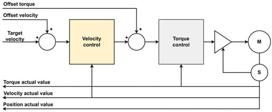
Figure 3.
Robot dynamic feedforward control system structure.
The final motion control of the industrial robot is determined by the planned curve. Any remaining vibration is expressed as a small amplitude oscillation with the end moment position of the trajectory as the equilibrium point. Assuming the terminal moment position of the robot is , the residual vibration in the time domain can be expressed as:
where represents the position of the robot at the end of its motion; represents the small amplitude oscillation generated by the robot. . The issue of decreasing the residual vibration of the robot can be reframed as the task of minimizing the position and velocity errors of the robot at the end moment. Based on the analysis above, the requirements for trajectory planning to suppress robot vibration can be summarized as follows:
- Ensure that the velocity, acceleration, and acceleration of the reference trajectory have continuous boundaries at the beginning and end of the motion.
- Largely suppresses the amplitude of the harmonic components in a specific frequency band.
- The goal is to minimize position and velocity errors in the trajectory at the termination moment and suppress residual vibrations of the robot.
4. Vibration Suppression System with Time-Lag Filtering for T-Track Interpolation
Reference [26] proposes a scheme for suppressing vibration using cable-driven parallel robots (CDPR) to protect the flexible wings of satellites from external interference and severe vibrations caused by rotation, avoid damage, and reduce energy consumption. The effectiveness of vibration suppression was evaluated through numerical simulations under the control of the proposed fuzzy PID method and active control method. Reference [27] proposes an optimal control method that is dependent on the pose to actively suppress tool tip vibration generated by periodic milling forces in robot milling. The method’s performance is evaluated through process-independent offset mass experiments and milling experiments, which showed that it can reduce tool tip vibration and improve robot milling accuracy. According to Reference [28], robots have low stiffness and are susceptible to vibration during the boring process, which can make it challenging to maintain machining quality. This article analyzes the vibration mechanism during robot boring processes and proposes a new vibration suppression method based on pressure feet. The effectiveness of the vibration suppression method was verified through a large number of boring experiments, which also confirmed the correctness of the vibration mechanism. Based on these references, this paper proposes a method for suppressing vibrations using time delay filtering and investigates the vibration mechanism of a 20 kg robot. A new concept of ‘straightness’ is introduced to assess the performance of the proposed method in comparison to other mainstream vibration suppression techniques.
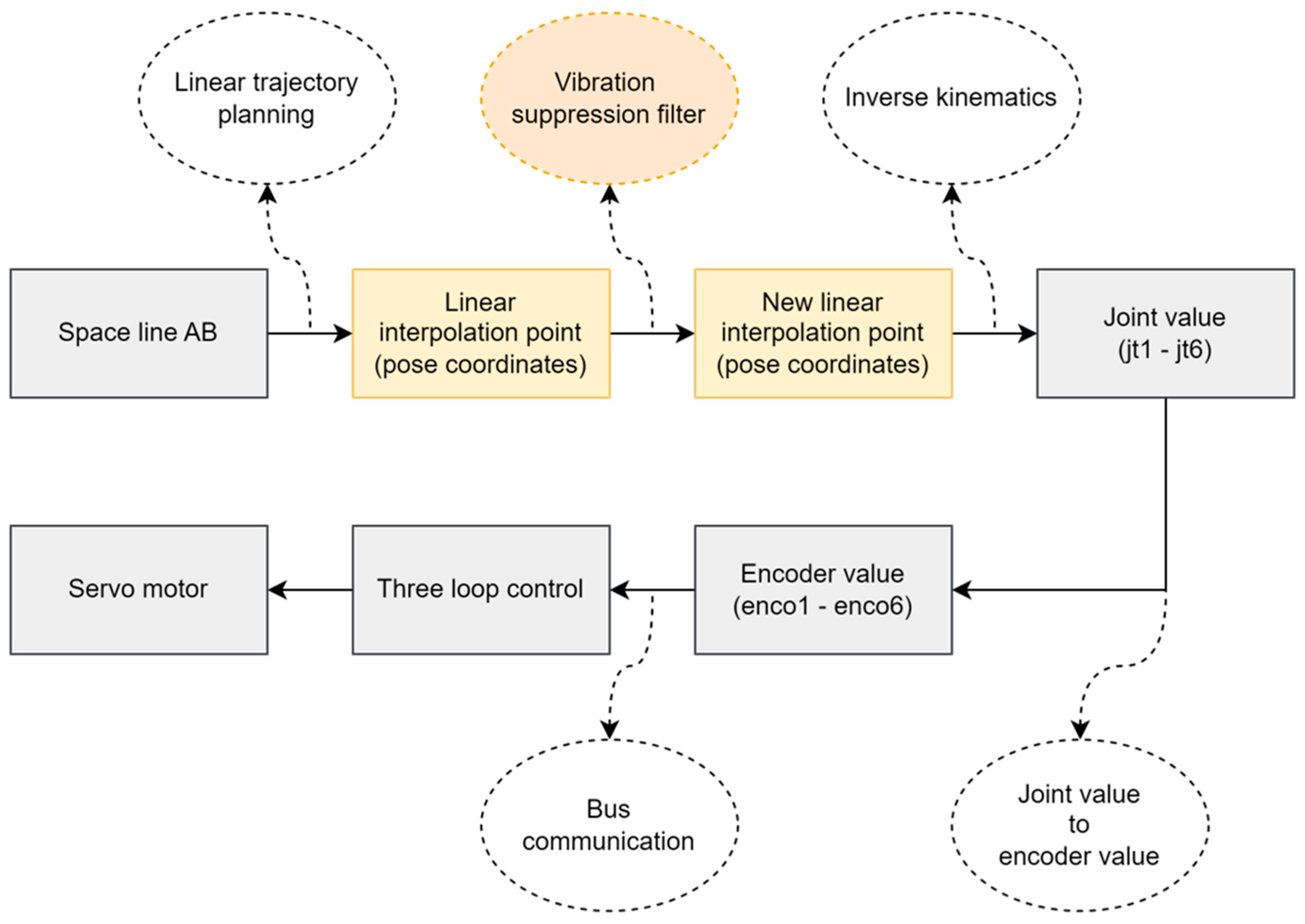
Figure 4 shows a control system that utilizes the time-lag filtering method to improve system performance by adjusting the output trajectory. This method involves selecting a specific frequency band based on the robot body’s vibration characteristics and designing a corresponding time-lag filter. The filtered signal trajectory can reduce vibration amplitude within the selected frequency band. Under ideal circumstances, robot body vibration can be reduced to zero through suppression or elimination.

Figure 4.
Solution of time-lag filtering based on T-planning.
Vibration suppression is a crucial concern in industrial robot control, particularly in applications that demand high accuracy and performance. The time-lag filtering method is particularly suitable for integration into the trajectory planning unit of a robot controller. This method can directly enhance performance through software algorithms without modifying the overall hardware and software structure of the controller.
4.1. T-Track Interpolation Strategy
When an industrial robot is assigned a task, it is typically provided with only the starting and ending positions. To generate the robot’s position, speed, and acceleration at each moment, specific strategies and methods are used. This process is known as trajectory interpolation, which enables the robot to create smooth paths and maintain smoothness during the motion process. The goal of T-trajectory interpolation is to ensure that the robot displays desirable motion characteristics while executing T-trajectories using appropriate mathematical algorithms and control strategies.
Acceleration:
Velocity:
Distance:
where denotes the maximum acceleration and denotes the time point of each stage. T-trajectory interpolation is a technique used to ensure that a robot exhibits smooth, accurate, and efficient motion when executing a T-trajectory. The use of T-trajectory interpolation helps to avoid robot instability when switching paths. This involves inserting additional points in the robot’s path to achieve the desired motion.
4.2. Principle of Input Time-Lag Filtering Method
Time-lag filtering is a technique used in control systems to suppress time-lag (delay) effects. It is a form of input shaping with significant features and applications in vibration suppression.
- Vibration Signal Monitoring: During a robot’s task, the robot control system monitors the vibration characteristics of the robot body in the operating space. These characteristics are obtained from the residuals of the actual trajectory relative to the theoretical trajectory, known as the trajectory residuals. The robot body exhibits undamped oscillation. The characteristics of the trajectory residuals can serve as the foundation for designing the time-lag filter parameters.
- Design of the Time-Lag Filter: The time-lag filter is a Finite Impulse Response (FIR) filter with parameters for amplitude, damping ratio, and time lag. The damping ratio and time lag are determined by the intrinsic frequency of the robot body, while the amplitude is determined by the damping ratio and time lag. By adjusting the parameters of the time-lag filter, it can be adapted to vibration signals of different frequencies and amplitudes.
- Multimodal Vibration Suppression: The robot body is composed of multiple rotary joints, each with different performance and load capacities. Therefore, the system exhibits multimodal vibration, which means that its response amplitude to multiple frequencies is significant. Filtering out the vibration of a single frequency alone does not produce a noticeable effect. To address this issue, a cascaded time-lag filter can be employed to suppress vibration across all frequency bands.
4.2.1. Time-Lag Filter Design Guidelines
The time-lag filtering method can be used to dynamically adjust the trajectory output in the curve of T-trajectory interpolation. This method suppresses the amplitude of harmonic components in specific frequency bands, primarily making it suitable for vibration suppression in complex and variable environments. By doing so, the robot system’s robustness and adaptability to vibration are improved. This method offers advantages in real-time performance and accuracy, providing an effective technical solution for industrial robots to move with high precision and stability, even under vibration disturbances. Each joint of the robot is considered a dynamical system, which is simplified to a second-order follower system.
where represents the undamped intrinsic frequency of the system, represents the system damping ratio, represents the system input, and represents the system output.
The unit impulse response of an underdamped system is given as:
In Equation (8), represents the damped intrinsic frequency of the system. The output of the system displays exponentially decaying oscillations. The rate of decay is determined by , while the frequency of the oscillation is determined by .
The output of the system with the addition of time-lag filtering is:
where is the number of pulses of the FIR, is the amplitude of each pulse, and is the time lag of each pulse. To meet the implicit condition of the system, which is that the robot’s termination position still matches the target position after adding the filter, the parameter of the filter must satisfy the following condition:
where represents the end moment of the pulse sequence action. Thus, it is that:
4.2.2. Zero-Vibration Time-Lag Filter Design
The expression for time-lag filtering in the time domain is:
The expression for time-lag filtering in the frequency domain is:
The residual vibration of the system can be defined as the impulse response in a steady state:
Among them,
By setting , the requirement of zero vibration can be satisfied. Its equivalent, Equations (14) and (15) are both zero.
However, the zero-vibration filter designed using the above method is only effective at . Additionally, the vibration suppression bandwidth is very narrow. It is necessary to increase the order of the filter, i.e., the number of pulses, to broaden the effective vibration suppression bandwidth.
To achieve a zero-vibration filter with N-pulses, the following conditions must be met:
The parameters for the N-pulse zero-vibration time-lag filter can be obtained by solving Equation (16) as follows:
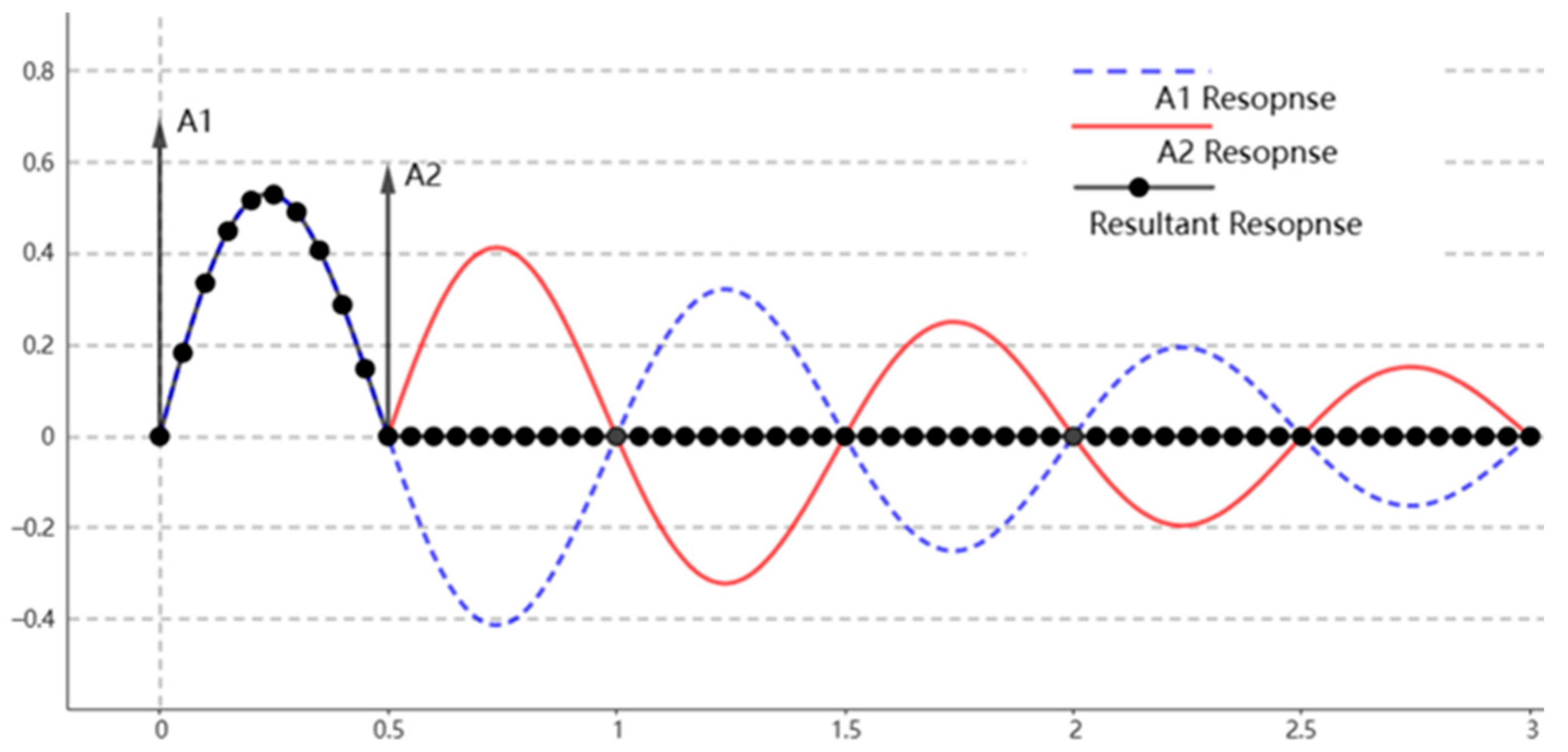
The time-lag filtering method convolves and filters the raw input signal with a given pulse before inputting it into the system to obtain a valid input signal. Figure 5 illustrates the working principle of input shaping using two pulses. The horizontal axis of the curve is measured in seconds (s) and the vertical axis is measured in millimeters (mm). When a pulse A1 is applied to a flexible system, it will cause the system to vibrate. The vibration response of an underdamped system is depicted in the figure above as the A1 response. If a second pulse, A2, is applied to the system with an amplitude opposite to that of the first pulse after one-half cycle, the vibration of the system will be completely suppressed. It is important to note that selecting the appropriate amplitude and duration of the second pulse is crucial in achieving effective vibration suppression. Ideally, complete suppression of vibration should be achieved.
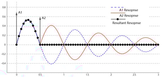
Figure 5.
Schematic diagram of input time-lag filtering method.
Filters can be designed according to Equation (17) to account for the multimodal vibration of industrial robots. It is important to determine the vibration of each mode and cascade the filters to maintain the kinematic synergy of all joints, avoiding differences in filter parameters that could disrupt it.
5. Experimental Analysis
The experiment compared two methods for suppressing vibrations in industrial robots: one based on closed-loop control of feedforward dynamics and the other based on T-trajectory interpolation time-lag filtering [29,30,31]. Table 1 shows the results of the experimental equipment used to test robot trajectory accuracy and stability, which included a dynamic signal test analyzer, laser tracker, and micrometer.

Table 1.
Experimental equipment.
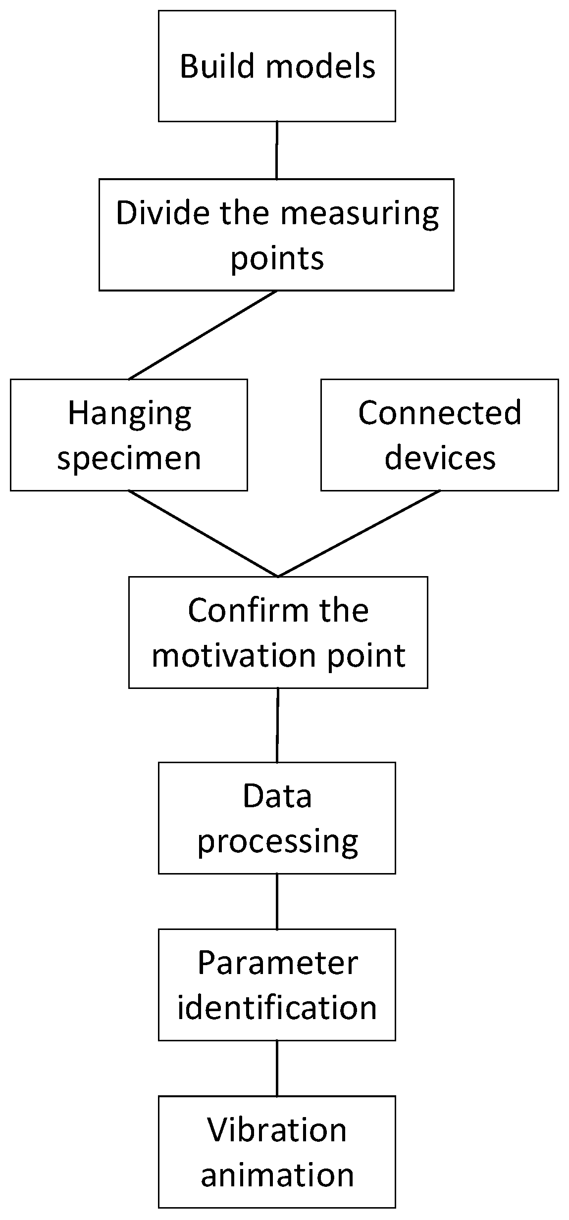
Figure 6 displays the flowchart of the vibration test conducted on an industrial robot.
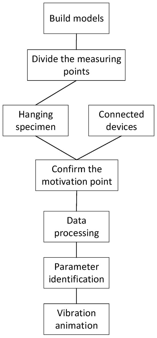
Figure 6.
Block diagram of test procedure.
Table 2 below shows the full-mode vibration angular frequency of the robot body as measured.
Table 2.
The angular frequency distribution of each joint vibration.
When the robot executes a motion command, the controller uses a cascaded mode of time-lag filter for each mode in the software algorithm. This filter is cascaded and specific to the joint involved in the motion, effectively suppressing any vibration.
The Laser tracker from FARO Company (Exton, PA, USA) was selected to measure the robot’s vibration trajectory in this experiment. The tracker has a measuring range of 40 m and an accuracy of 10 μm ± 8 μm/m. To meet the measurement requirements, the tracker’s accuracy of ±25 μm takes into account the sphericity error of the target ball and the spatial distance between the tracker and the robot during measurement. The experiment described in this paper employs a sampling period of 1 ms, which corresponds to the robot’s communication period.
5.1. Trajectory Interpolation Test
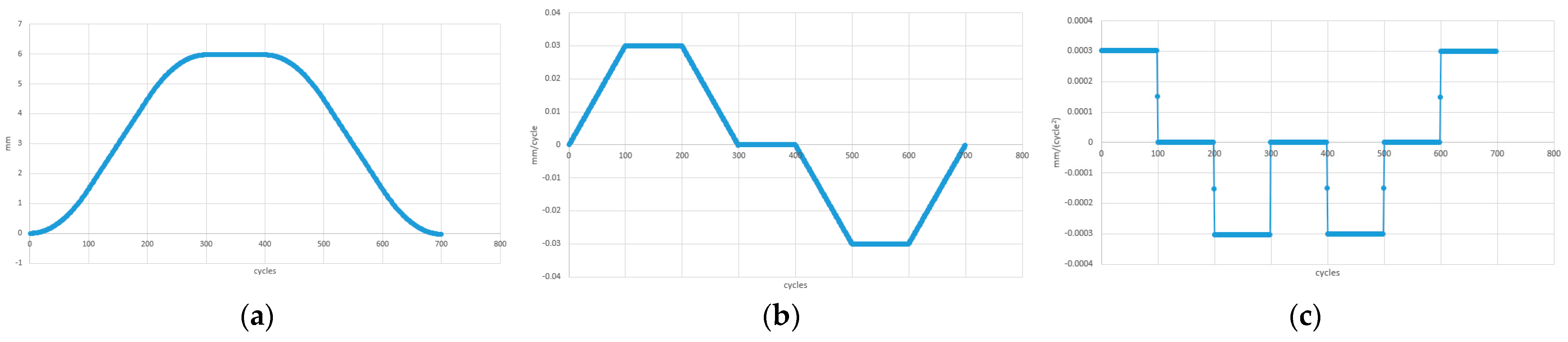
The trajectory interpolation test is a prerequisite for the vibration suppression method based on T-trajectory interpolation time-lag filtering. To achieve vibration suppression, time-lag filtering must be combined with T-track interpolation. The trajectory interpolation curve of the industrial robot was collected and tested to verify key features such as smooth transition, trajectory optimization, and speed planning. To improve the accuracy and efficiency of the automation system, T-trajectory interpolation was used to ensure a smooth trajectory of the industrial robot. As shown in Figure 7a–c, the horizontal axis of the curve is measured in cycles/16 ms, while the vertical axis is measured in mm. The goal of T-trajectory interpolation is to improve the accuracy and efficiency of the automation system by achieving ideal motion characteristics.
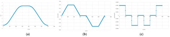
Figure 7.
(a) Location curves for T-planning; (b) velocity curves for T-planning; (c) acceleration curves for T-planning.
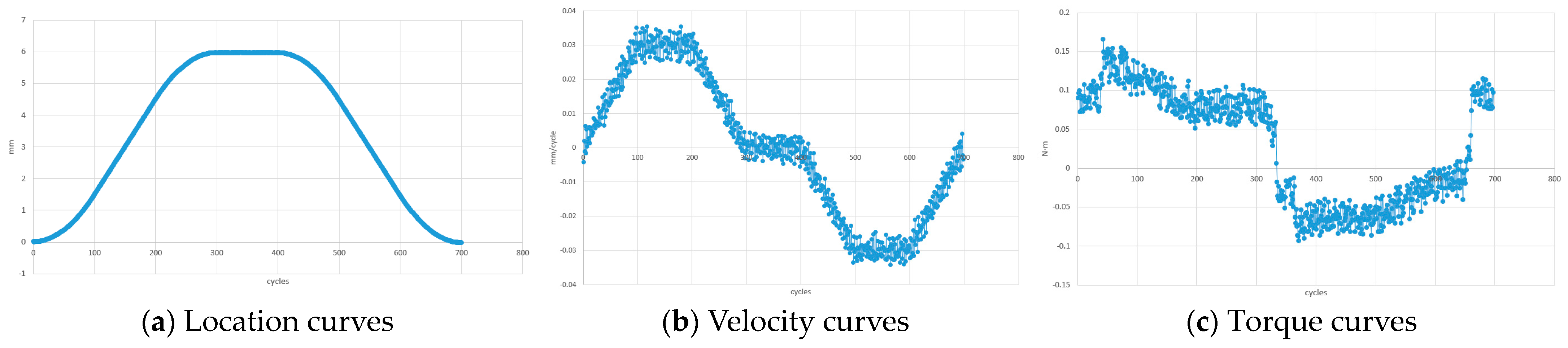
The trajectory curves without vibration suppression are shown in Figure 8, from which it can be seen that the robot’s velocity and torque have large amplitudes that affect the control. The robot is controlled in synchronized position mode, and although it also has a certain amplitude on the position curve, it is not significant enough relative to its position scale.
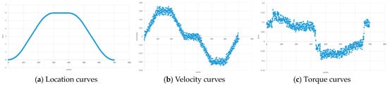
Figure 8.
Actual trajectory without vibration suppression.
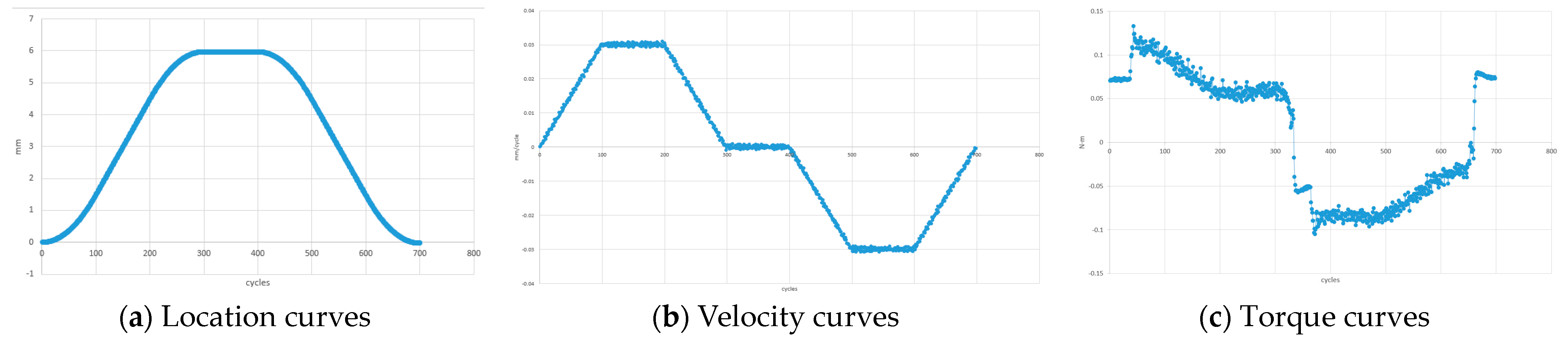
As shown in Figure 9, the inclusion of vibration suppression considerably enhances the amplitude of the robot’s velocity profile while mitigating the impact of vibration.
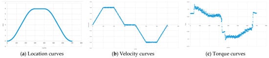
Figure 9.
Actual trajectory with vibration suppression.
The experimental results suggest that ensuring smooth transitions between target points in T-trajectory interpolation leads to vibration-free and stable transitions, which helps avoid robot instability during path switching. Trajectory optimization shapes the trajectory to meet specific motion conditions by considering factors such as the shortest path, minimum acceleration/deceleration, and minimum mechanical stress. Velocity planning and T-trajectory interpolation are utilized to enhance system stability by achieving appropriate velocity variations throughout the trajectory and ensuring the necessary conditions for the vibration suppression method of time-lag filtering.
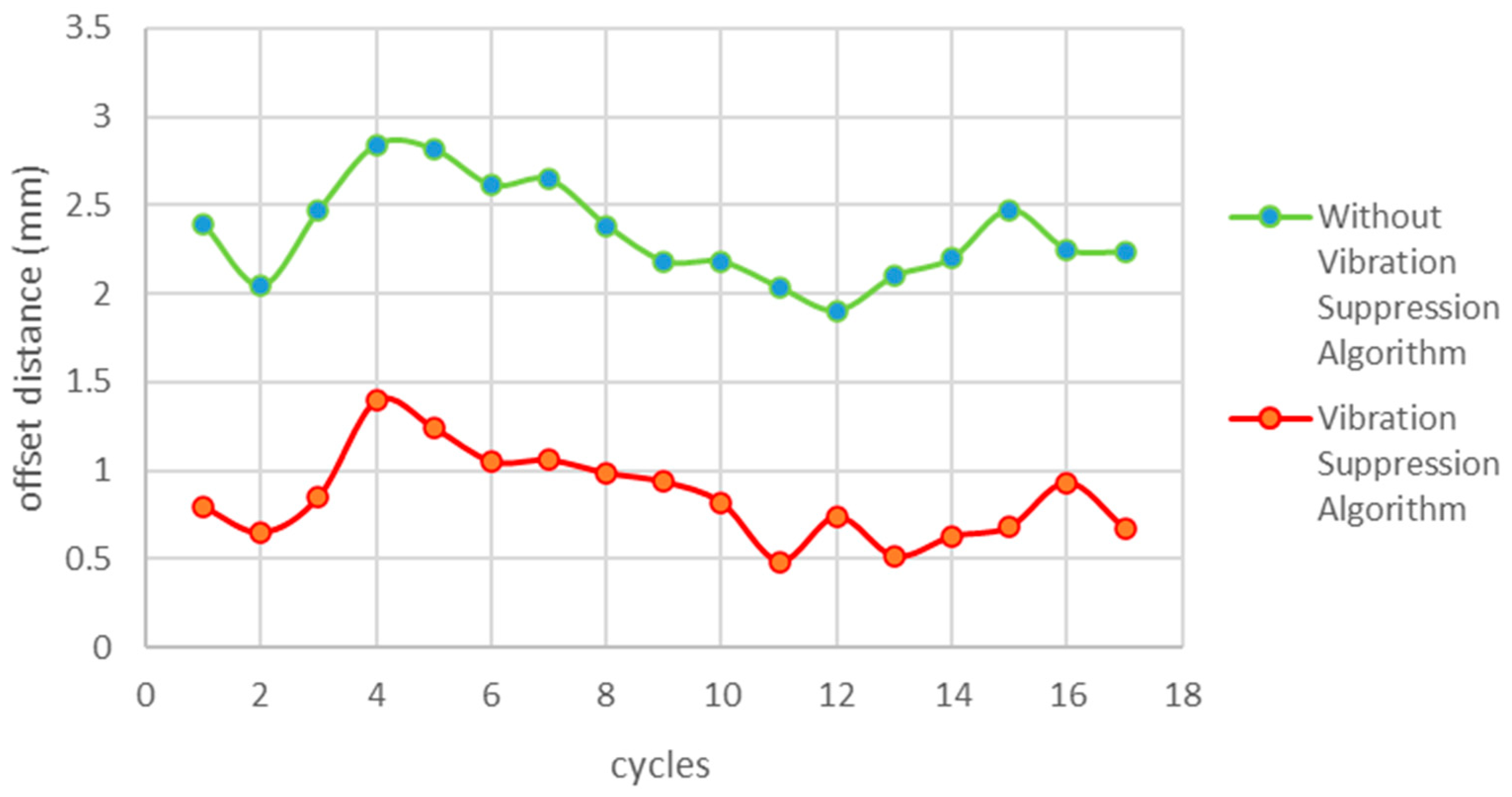
5.2. Straightness Vibration Suppression Test
The accuracy of an industrial robot’s straight-line walking ability is reflected in its straightness test results. This is a test of straightness vibration suppression for industrial robots. Straightness motion is the most used method for inducing vibration in industrial robots. It provides an intuitive response to the vibration of each joint of the robot, allowing for the assessment of the effect of joint vibration on the robot. The experiments on straightness vibration suppression have shown that the time-lag filtering method is superior to the vibration method based on closed-loop control of the dynamic feedforward. Figure 10, Figure 11 and Figure 12 demonstrate the effectiveness of the time-lag filtering method in suppressing robot vibration at various speeds.
At a straightness velocity of 30%:
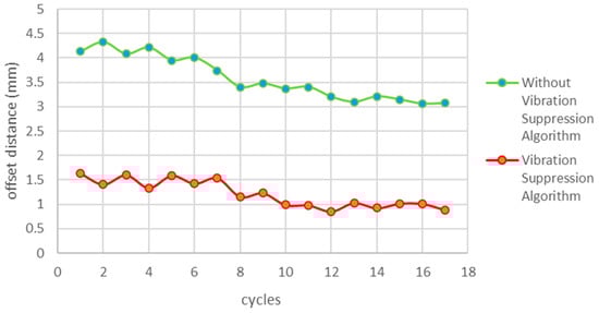
Figure 10.
Straightness vibration suppression at 30% of straightness velocity.
Figure 10.
Straightness vibration suppression at 30% of straightness velocity.

At a straightness velocity of 150%:

Figure 11.
Joint vibration suppression at 150% of straightness velocity.
Figure 11.
Joint vibration suppression at 150% of straightness velocity.
At a straightness velocity of 300%:
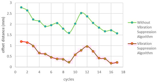
Figure 12.
Straightness vibration suppression at 300% of straightness velocity.
Figure 12.
Straightness vibration suppression at 300% of straightness velocity.

The time-lag filtering technique is an effective means of motion control for industrial robots. It is expected to improve the performance of robots and meet the increasing demand for precision and efficiency in modern manufacturing. However, time-lag filtered control systems are subject to certain delays.
5.3. Comparison of Methods for Vibration Suppression
Due to the difference between the trajectory of robot teaching and speed parameters, the deviation value of vibration may be different. However, it is necessary to compare only under the same conditions.
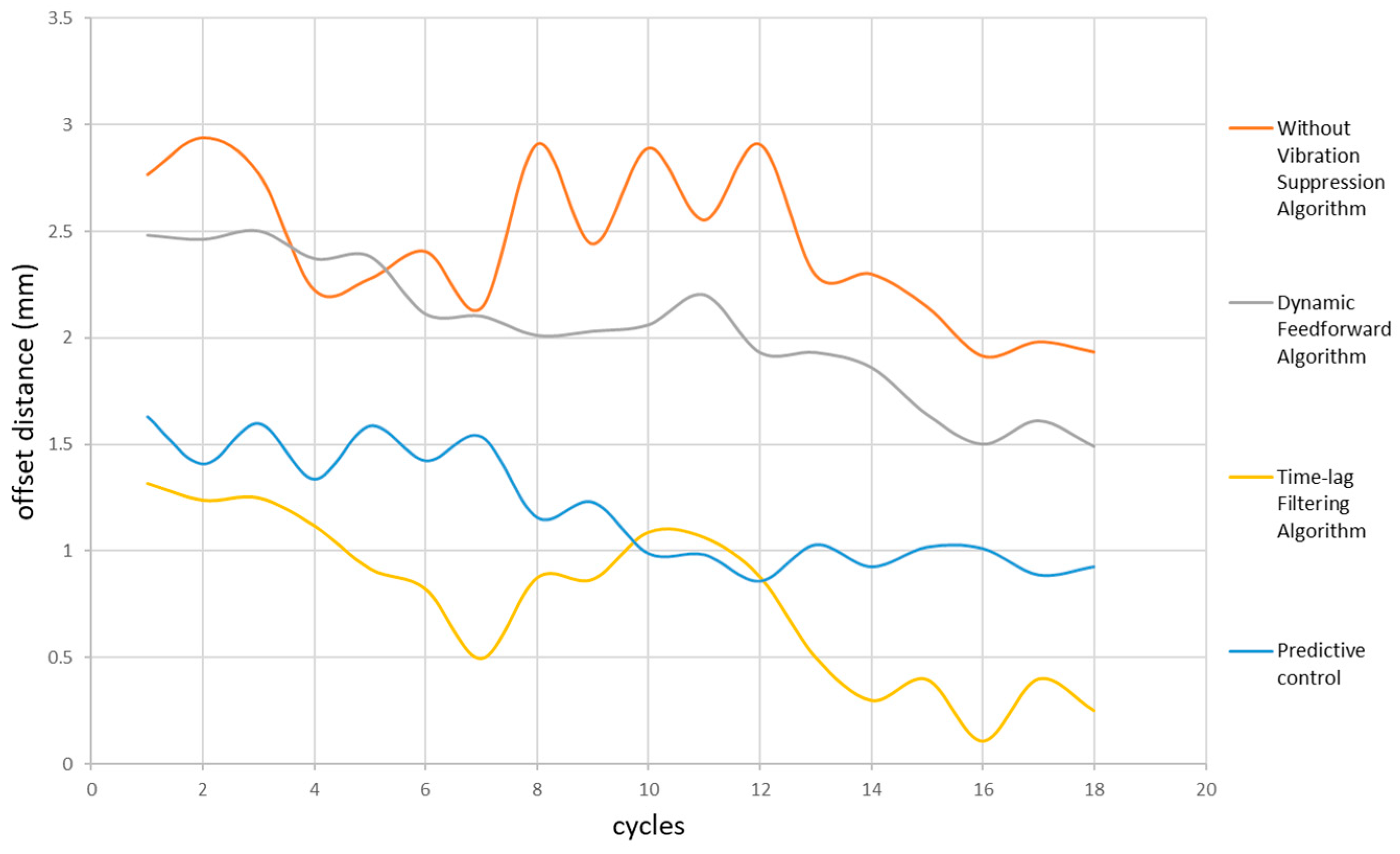
To evaluate the actual vibration effect of the relevant vibration suppression algorithms (predictive control algorithm, time-lag filtering algorithm, and dynamic feedforward algorithm) on the robots, a comparative test was carried out. Four sets of offset distance values were collected for Formula (18).
Figure 13 demonstrates that time-lag filtering is more effective than other algorithms in suppressing vibrations and enabling the robot to achieve a higher level of trajectory coincidence. The degree of trajectory coincidence is an important indicator of the robot’s ability to maintain trajectory planning, and using time-lag filtering is a viable approach to improving this ability.
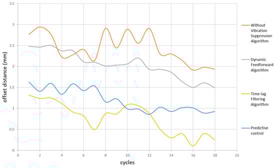
Figure 13.
Comparison of methods for vibration suppression.
Table 3 shows that the time-lag filtering method and dynamic feedforward control method are superior to other methods in terms of vibration suppression. The delay filtering method has the best vibration suppression effect and can improve robot vibration performance.
Table 3.
Comparison of straightness.
5.4. Analysis of Experimental Results
We use “Average Amplitude Ratio” as a measure of the vibration suppression effect, abbreviated as AAR.
where n is the number of laser tracker acquisition points, Si is the amplitude after vibration suppression, and Ui is the amplitude before vibration suppression.
Comparison of the classical methods with the method proposed in this paper: the predictive control method has an AAR of 0.841, the dynamic feedforward method has an AAR of 0.498, and the time-lag filtering method proposed in this paper has an AAR of 0.306. The vibration suppression effect increases as the AAR decreases.
In summary, the method proposed in this paper can reduce the AAR from 0.841 and 0.498 to 0.306 compared with the classical methods, which has a more significant improvement effect.
6. Conclusions
This study explores the application of the T-planning-based time-lag filtering technique in suppressing vibrations in robotic systems. Time-lag-induced vibrations can negatively impact system performance and lead to unstable control behavior. The problems associated with vibration suppression systems are described in detail, including some of the reasons for the occurrence of vibrations. The paper thoroughly analyzes and compares the advantages and disadvantages of closed-loop control-based dynamic feedforward. Additionally, it proposes a vibration suppression method based on time-lag filtering with T-trajectory interpolation. The robotic system can respond more accurately to external commands by designing zero-vibration time-lag rate filters for each vibration mode and cascading them, thus reducing vibration. The results indicate that the time-lag filter, which is based on T-trajectory interpolation, is significantly more effective than the dynamic feedforward method, which is based on closed-loop control, in suppressing robot vibrations. This leads to a significant improvement in the robot system’s vibration performance. Time-lag filtering provides a more reliable response for the robot, particularly in tasks requiring high-precision control, which enhances its reliability and accuracy in performing tasks.
Future research could investigate the optimization and extension of time-lag filtering in different types of robotic systems and various application scenarios to better adapt to evolving robotics needs.
Author Contributions
Methodology, S.L.; Software, S.L. and C.W.; Validation, R.S.; Formal analysis, L.L.; Resources, L.L.; Data curation, C.W. and B.Z.; Writing—review and editing, B.Z.; Project administration, R.S. All authors have read and agreed to the published version of the manuscript.
Funding
This research was funded by the National Key Research and Development Plan: Heavy Duty Industrial Robot Development and Application (2023YFB4705102).
Data Availability Statement
Data are contained within the article. The vibration suppression test is openly available in Github at https://github.com/LSC-neu/Vibration-suppression (accessed on 2 April 2024).
Conflicts of Interest
Authors Shichang Liu, Liang Liang, Bin Zhao and Ruohuai Sun were employed by the company SIASUN Robot & Automation Co., Ltd. The remaining authors declare that the research was conducted in the absence of any commercial or financial relationships that could be construed as a potential conflict of interest.
References
- Zheng, K.; Zhang, Q.; Zeng, S. Trajectory control and vibration suppression of rigid-flexible parallel robot based on singular perturbation method. Asian J. Control 2022, 24, 3006–3021. [Google Scholar] [CrossRef]
- Sun, H.; Hou, S.; Li, Q.; Tang, X. Research on the configuration of cable-driven parallel robots for vibration suppression of spatial flexible structures. Aerosp. Sci. Technol. 2021, 109, 106434. [Google Scholar] [CrossRef]
- Yong, T.; Xiang, Y.; Yan, F.; Binzhang, J. Vibration behavior analysis and vibration suppression studies of the space robot. Int. J. Aerosp. Eng. 2022, 2022, 3641051. [Google Scholar] [CrossRef]
- Liu, C.; Chen, Y. Combined S-curve feedrate profiling and input shaping for glass substrate transfer robot vibration suppression. Ind. Robot. 2018, 45, 549–560. [Google Scholar] [CrossRef]
- Kim, J.; Croft, E.A. Preshaping input trajectories of industrial robots for vibration suppression. Robot. Comput. Integr. Manuf. 2018, 54, 35–44. [Google Scholar] [CrossRef]
- Newman, M.; Lu, K.; Khoshdarregi, M. Suppression of robot vibrations using input shaping and learning-based structural models. J. Intell. Mater. Syst. Struct. 2021, 32, 1001–1012. [Google Scholar] [CrossRef]
- Tian, Y.; Yue, X.; Wang, L.; Feng, Y. Vibration suppression of collaborative robot based on modified trajectory planning. Ind. Robot. 2023, 50, 45–55. [Google Scholar] [CrossRef]
- Huang, X.; Song, Y.; Li, Q.; Xiao, X. A vibration suppression algorithm for industrial robot joint servo system based on internal model control. Dian Gong Ji Shu Xue Bao 2019, 34, 497. [Google Scholar] [CrossRef]
- Boscariol, P.; Richiedei, D.; Tamellin, I. Residual vibration suppression in uncertain systems: A robust structural modification approach to trajectory planning. Robot. Comput. Integr. Manuf. 2022, 74, 102282. [Google Scholar] [CrossRef]
- Jia, S.; Jia, Y.; Xu, S.; Hu, Q. Maneuver and active vibration suppression of free-flying space robot. IEEE Trans. Aerosp. Electron. Syst. 2018, 54, 1115–1134. [Google Scholar] [CrossRef]
- Li, B.; Cui, G.; Tian, W.; Liao, W. Vibration suppression of an industrial robot with AGV in drilling applications by configuration optimization. Appl. Math. Model. 2022, 112, 614–631. [Google Scholar] [CrossRef]
- Zhang, T.; Chu, H.; Zou, Y.; Liu, T. A deep reinforcement learning-based optimization method for vibration suppression of articulated robots. Eng. Optim. 2023, 55, 1189–1206. [Google Scholar] [CrossRef]
- Li, F.; Cao, J.; Wu, S.; Wu, P.; Zhu, Z. Intelligent algorithms for six degrees of freedom robot trajectory planning considering vibration suppression. J. Phys. Ser. 2022, 2365, 12042. [Google Scholar] [CrossRef]
- Kakou, P.; Bukhari, M.; Wang, J.; Barry, O. On the vibration suppression of power lines using mobile damping robots. Eng. Struct. 2021, 239, 112312. [Google Scholar] [CrossRef]
- Ilman, M.M.; Yavuz, Ş.; Karagülle, H.; Uysal, A. Hybrid vibration control of an industrial CFRP composite robot-manipulator system based on reduced order model. Simul. Model. Pract. Theory 2022, 115, 102456. [Google Scholar] [CrossRef]
- Kraus, K.; Šika, Z.; Beneš, P.; Krivošej, J.; Vyhlídal, T. Mechatronic robot arm with active vibration absorbers. J. Vib. Control 2020, 26, 1145–1156. [Google Scholar] [CrossRef]
- Maki, T.; Zhao, M.; Okada, K.; Inaba, M. Elastic vibration suppression control for multilinked aerial robot using redundant degrees-of-freedom of thrust force. IEEE Robot. Autom. Lett. 2022, 7, 2859–2866. [Google Scholar] [CrossRef]
- Yi, J.; Zhu, Q.; Wu, J.; Xiong, R. Walking vibration suppression for humanoid robot based on optimal control. Ji Qi Ren A J. Chin. Assoc. Autom. 2018, 40, 129. [Google Scholar] [CrossRef]
- Sancak, C.; Itik, M. Out-of-plane vibration suppression and position control of a planar cable-driven robot. IEEE/ASME Trans. Mechatron. 2022, 27, 1311–1320. [Google Scholar] [CrossRef]
- Ueno, Y.; Tachiya, H. Suppressing residual vibration caused in objects carried by robots using a heuristic algorithm. Precis. Eng. 2023, 80, 1–9. [Google Scholar] [CrossRef]
- Jalendra, C.; Rout, B.K.; Marathe, A. Vision sensor based residual vibration suppression strategy of non-deformable object for robot-assisted assembly operation with gripper flexibility. Ind. Robot 2022, 49, 851–864. [Google Scholar] [CrossRef]
- Boscariol, P.; Gasparetto, A. Vibration suppression of speed-controlled robots with nonlinear control. Front. Mech. Eng. 2016, 11, 204–212. [Google Scholar] [CrossRef]
- López-Linares, S.; Konno, A.; Uchiyama, M. Vibration suppression control of 3D flexible robots using velocity inputs. J. Robot. Syst. 1997, 14, 823–837. [Google Scholar] [CrossRef]
- Elvira-Ortiz, D.A.; Romero-Troncoso, R.D.J.; Jaen-Cuellar, A.Y.; Morales-Velazquez, L.; Osornio-Rios, R.A. Vibration suppression for improving the estimation of kinematic parameters on industrial robots. Shock. Vib. 2016, 2016, 6954012. [Google Scholar] [CrossRef]
- Perner, M.; Krombholz, C.; Monner, H.P. Approach for a smart device for active vibration suppression as an add-on for robot-based systems. J. Mech. Sci. Technol. 2014, 28, 4407–4413. [Google Scholar] [CrossRef]
- Nguyen, V.; Johnson, J.; Melkote, S. Active vibration suppression in robotic milling using optimal control. Int. J. Mach. Tools Manuf. 2020, 152, 103541. [Google Scholar] [CrossRef]
- Phan, V.P.; Goo, N.S.; Park, H.C. Vibration suppression of a flexible robot manipulator with a lightweight piezo-composite actuator. Int. J. Control Autom. Syst. 2009, 7, 243–251. [Google Scholar] [CrossRef]
- Guo, Y.; Dong, H.; Wang, G.; Ke, Y. Vibration analysis and suppression in robotic boring process. Int. J. Mach. Tools Manuf. 2016, 101, 102–110. [Google Scholar] [CrossRef]
- Lahssan, T.; Mohammed, B.; Badr, I. Robustifying hierarchical sliding mode control for active vibration suppression of a flexible manipulator using integral sliding mode control. Int. J. Intell. Robot. Appl. 2023, 7, 641–651. [Google Scholar] [CrossRef]
- Gao, W.; Ibaraki, S.; Donmez, M.A.; Kono, D.; Mayer, J.R.R.; Chen, Y.; Szipka, K.; Archenti, A.; Linares, J.; Suzuki, N. Machine tool calibration: Measurement, modeling, and compensation of machine tool errors. Int. J. Mach. Tools Manuf. 2023, 187, 104017. [Google Scholar] [CrossRef]
- Hazrat, B.; Baoqun, Y.; Muhammad, A.; Zeeshan, A.; Avinash, R.; Wang, Y. A practical study of active disturbance rejection control for rotary flexible joint robot manipulator. Soft Comput. 2023, 27, 4987–5001. [Google Scholar] [CrossRef]

Disclaimer/Publisher’s Note: The statements, opinions and data contained in all publications are solely those of the individual author(s) and contributor(s) and not of MDPI and/or the editor(s). MDPI and/or the editor(s) disclaim responsibility for any injury to people or property resulting from any ideas, methods, instructions or products referred to in the content. |
© 2024 by the authors. Licensee MDPI, Basel, Switzerland. This article is an open access article distributed under the terms and conditions of the Creative Commons Attribution (CC BY) license (https://creativecommons.org/licenses/by/4.0/).