1. Introduction
At present, there are many possibilities when it comes to improving the surface roughness and deburring of workpieces after the manufacturing process. Vibratory finishing, barrel tumbling, disc finishing, stream finishing, and drag finishing are the most widely used among multiple other methods; however, the choice of a particular technology for mass workpiece finishing depends on multiple factors [
1,
2,
3]. Technology used for finishing, process parameters, workpiece materials, the entry surface state of the part, and the desired output quality all need to be taken into consideration. Most manufacturers of mass finishing machines make a distinction between workpiece and tool finishing, since more control over the process is needed for tool modification due to the demand for high accuracy and repeatability. However, a review of deburring and finishing processes for workpieces, while containing a categorization of mass finishing processes, did not specifically mention drag finishing in relation to workpiece processing [
4]. Other authors evaluated the cemented carbide material removal rates of different abrasive media for drag finishing technology. K-factor formation was also investigated. The best surface roughness was achieved by the abrasive with the highest material removal rate (MRR) [
5]. Automation of the mass finishing processes was developed, and it was found out that the material removal rate of robot-guided centrifugal disc finishing is significantly higher compared to unguided centrifugal disc finishing. Two different finishing media were used. Technology like this can be used for time-efficient deburring and surface finishing operations. However, the minimal achievable average roughness parameter Ra in robot-guided centrifugal disc finishing is higher compared to the unguided process. In addition, a material removal model based on the discrete element method is presented. The model is valid for both unguided and robot-guided centrifugal disc finishing. The model can be used as a universal tool to design centrifugal disc finishing processes without using a time- and cost-intensive trial and error approach [
6]. Another feature of tool drag finishing machines is the specialized tool holder, which in most cases is not suitable for workpiece clamping. An active workpiece holder that adds vibrations and axial rotation is utilized for an investigation of centrifugal disc finishing of AISI 304 stainless steel. An increase in the material removal rate is observed for the rotary oscillation movement of the workpiece. Better surface roughness is also achieved by this process due to the increased frequency of contact of the workpiece with the abrasive [
7]. The vibration-assisted finishing process has also been utilized for microfinishing of magnesium alloy parts using a vertical vibration-assisted magnetic abrasive process. The deburring efficiency increases with vibration assistance, reducing the time needed to remove the burrs [
8]. The prototype machine used for the experiments described in the paper allows for easy swapping of the tool and workpiece holders, potentially enabling multi-purpose operation.
The mechanism of material removal when drag finishing not only affects the surface quality, but can also influence the geometric and dimensional characteristics of the workpieces. The effect of finishing on these aspects has not yet been thoroughly investigated, considering the multitude of parameters that influence the outcome of the process. The type of finishing medium, speed of rotation, direction change, tilt angle, immersion depth, and process time all affect the final quality of the workpiece. The processing time and the abrasive media have a substantial influence on the measured surface roughness. The wear resistance of samples subjected to post-processing drag finish showed a notable increase as compared to the wear resistance of the as-built sample. Rotational speed and abrasive media play key roles in further enhancing the wear resistance of the Ti-6Al-4V alloy fabricated by laser powder bed fusion. Drag finish post-processing plays a notable role in enhancing the wear resistance and controlling the wear rate, as well as the wear mechanism, of additively manufactured titanium alloy [
9]. Other authors have measured the internal velocity of finishing media in a mass finishing process. The effect of the workpiece’s location on the media flow direction has been investigated, as it affects the material removal rate and overall finishing performance [
10]. Another approach is to develop a numerical model of the finishing process that can be used for simulation, such as an investigation of the centrifugal disc finishing process parameters by the discreet element method. A numerical model of a centrifugal disc finishing process has been developed, which focusses on determining the distribution of kinetic energy in a working medium, has been developed [
11]. The rheological properties of mass finishing media using a mathematical model of flow have been also investigated. Subsequent experimental tests have measured the forces and abrasive medium. The correlation between experimental drag finishing tests and numerical test results reveals the physical mechanisms at the interface between the medium and the surface [
12]. The non-linear discrete element model of the drag-finishing process was developed and verified by the simulation results of the real experiment. Local contact intensities can be determined by the model [
13]. Wet finishing processes have also been a subject of research. A novel method of drag finishing is presented in combination with fluidized bed abrasive finishing. The designed equipment allowed for an improvement of the surface finish with a high level of accuracy and in a short time [
14]. The influence of filtering the lubricant on the wet drag-finishing process has also been investigated. Filtration of the lubricant reduces the achieved roughness and material deformation on the surface [
15].
If desired tolerances are to be achieved with certain repeatability, it is necessary to investigate how each of the aforementioned parameters and their interactions change the observed aspects of the workpiece. While some research has been carried out on finishing multiple materials, comprehensive investigation into how a different workpiece material changes the outcome and, therefore, the requirements of the drag-finishing process seem to be lacking. One study investigated the influence of stream finishing process parameters on samples of AISI 4140 material. The results indicate that both the depth of immersion depth and the angle of the workpiece exert a substantial influence on the depth of residual stress observed within the material [
16]. Another study focused on the high-speed stream finishing process applied to tempered AISI 4140 material, wherein an observation of surface grain refinement was documented. Higher rotational speeds during the process were observed to result in elevated surface roughness levels compared to those achieved at conventional speeds [
17]. Different investigations have examined the impact of surface finishing on the surface roughness of resin-based composite materials, with findings indicating that both the composite type and the finishing method play significant roles in determining the surface roughness of the composites [
18]. The parameters involved in centrifugal disc finishing of Ti-6Al-4V workpieces were examined by another study, the results of which reveal that both the type of media and the rotational speeds exert notable influences on the achieved roughness of the workpieces. Specifically, higher rotational speeds correlate with increased surface roughness [
19]. More authors have investigated the stream finishing process and its impact on the micro hardness, residual stresses, and surface topography when finishing AISI 4140 workpieces [
20]. Additional investigations have examined the drag-finishing process applied to aluminum parts by utilizing spherical abrasive media alongside a chemical accelerator additive, and have observed plastic deformation in addition to an increase in the material removal rate. Furthermore, this highlights that the oxidizing chemical accelerator contributes to the enhancement of the material removal rate and exerts a positive influence on the surface roughness of the workpieces [
21]. Recently, the use of the mass finishing process for additively manufactured parts has become a subject of research. Some authors have investigated the effects of centrifugal disc finishing on additively manufactured metal components. A considerable improvement in surface roughness was observed. Mechanical testing showed that surface finishing had no influence on the formation of cracks within the components [
22]. Surface roughness after drag finishing was reduced compared to the as-built state, and the microhardness of the surface layer was found to be hardened compared to the bulk of the maraging sample. Drag finishing had a negative effect on the corrosion performance of selective laser-melted maraging steel components due to the formation of cracks in the surface layer [
23]. The objective of the research presented herein was to experimentally determine the effectiveness of high-speed drag finishing for the modification of workpieces of different materials and with various initial surface roughness values. The area of use for the particular finishing technology proposed herein is for the precision finishing of accurate workpieces where a significant degree of control over the process and its outcome is required. The prototype machine can reach approximately 60% higher rotations per minute and, therefore, higher angular velocities than current commercially available machines. However, this can also lead to a negative influence of the process because of changes in the flow of the media in relation to the workpiece. If the process would prove to be effective when adapted for workpiece finishing and deburring, it would indicate the viability of expanding the function of the prototype device for this task, making it a multi-purpose drag finishing machine.
2. Materials and Methods
Three different materials were used for the workpiece samples: austenitic stainless steel 316L (ASTM A240/A240M) [
24], carbon steel C45 (DIN EN 10083-2) [
25], and aluminum alloy 6082 (BS EN 573-3) [
26]. Mechanical properties such as hardness, tensile strength, and ductility differ for each of these materials. As a result, the drag-finishing process should result in a different outcome for each material. The selected mechanical properties are listed in
Table 1.
The shape of the sample was a cylinder with a diameter of 14 mm and a length of 40 mm. Samples were manufactured by turning on a DMG CTX alpha 500 multi-axis turning center. Different feed values were used to achieve target machined surface roughness, but the cutting speed
vc and the depth of cut
ap were kept constant. The cutting parameters are listed in
Table 2.
Machined surface roughness was measured using a Mitutoyo (Kawasaki, Japan) SJ-210 portable surface roughness tester. The measurement parameters, namely, cut-off length
λc, evaluation length
ln, measurement speed
v, and short-wave filter
λs, are listed in
Table 3. The machined surface area was measured across the layout three times at different places, and three parameters—
Ra (arithmetical mean height of the evaluated profile),
Rq (root mean square deviation of the evaluated profile), and
Rz (maximum height of the evaluated profile)—were recorded. The surfaces of the samples were then measured periodically during the drag-finishing process.
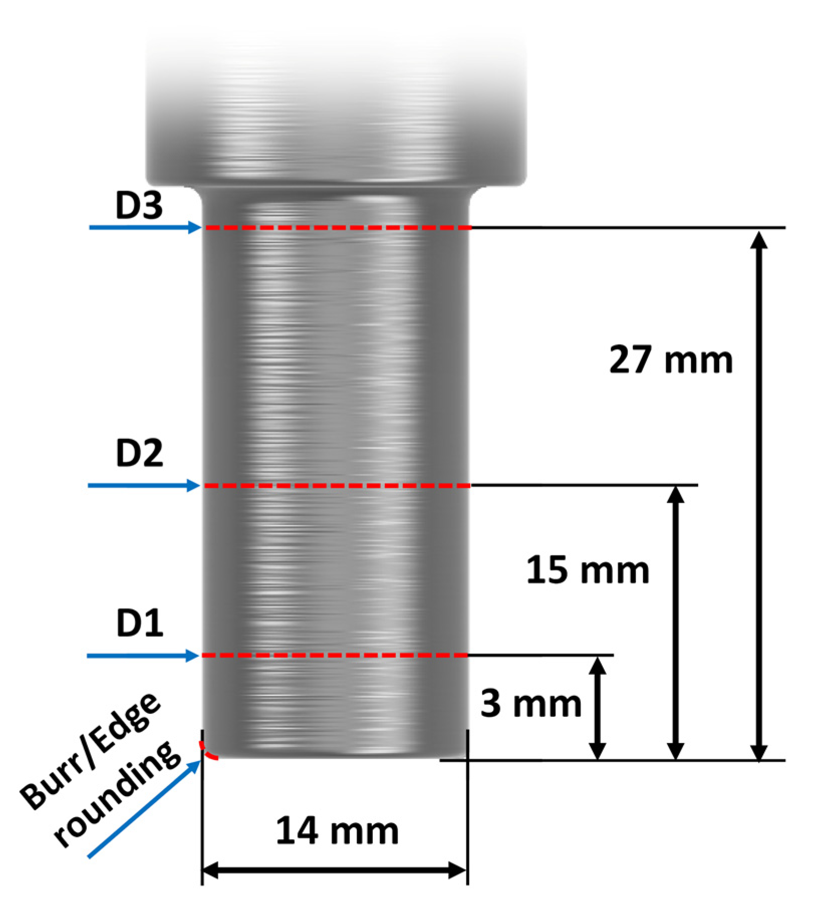
The dimensions of each sample were measured on a Zeiss (Jena, Germany) CenterMax coordinate measuring machine. The measurement was carried out before the drag-finishing process and then continued in the same way as the surface roughness measurement. The diameter of the samples was measured at three levels so that, in addition to the change in dimensions, the deviation of the shape could be evaluated. The distances of measurement from the top face of the sample were 3, 15, and 27 mm. This, along with the edge burr or rounding measurement, is visualized in
Figure 1.
The Zeiss VAST XTR touch probe with a ruby ball of 3 mm diameter was used, and for each diameter, 500 points of contact were measured. The probe was calibrated prior to measurement with a deviation of 0.04 µm. The Zeiss Calypso software (version 7.4.04) was used to create a measurement program to ensure that all samples were measured using the same method. Another change observed on the samples was the burr on the edge that resulted from the machining operation. This was measured using an Alicona (Graz, Austria) InfiniteFocus optical microscope throughout the drag-finishing process. The measurement parameters are given in
Table 4. An objective lens with a magnification of 10× was used for the measurement. The sample was observed at an angle of 45 degrees to scan as much of the burr as possible. The appropriate lighting was selected during the measurement. After the areas of focus on the workpieces were scanned, a coordinate system was established, enabling the measurement. The best-fit method was used for computation. The contour measurement method was then used. A shape of burr or edge rounding was obtained using a plane cut of the scanned model. Distance measurement was used to determine the height of the burr. After the burr was removed, edge rounding formation was measured instead. For the measurement of the edge rounding, a circle measurement method was used.
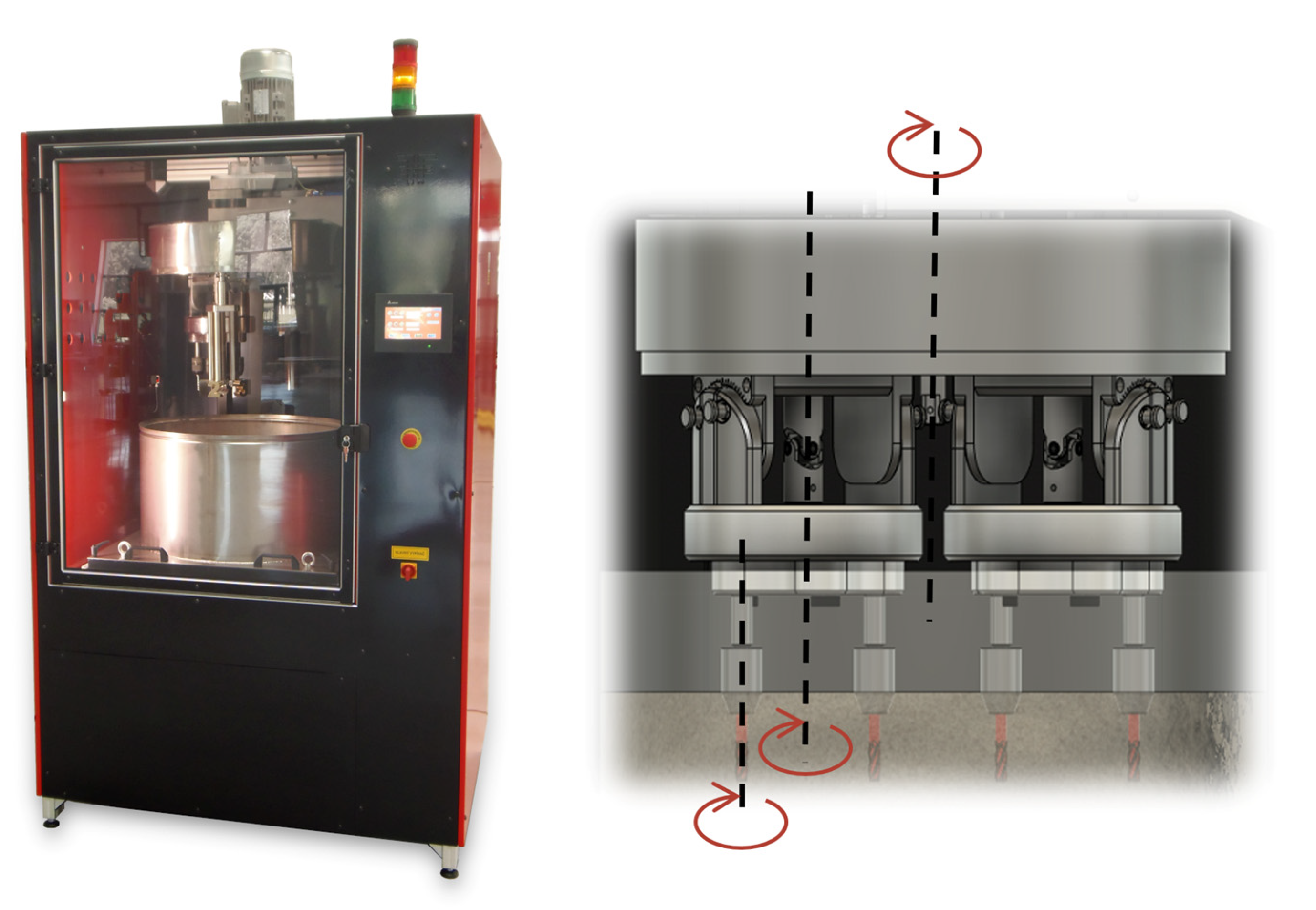
The processing of the samples was performed on a prototype high-speed drag finishing machine developed in the laboratory of 5-axis machining at the Faculty of Materials Science and Technology of the Slovak University of Technology. The kinematic structure of the machine was the same as that of commercially used machines. Illustrations of both the machine and the movement structure are shown in
Figure 2.
For the experiments, a fixture for cutting edge preparation was used for processing along three axes. The samples rotated during drag finishing around the rotor axis, the holder axis, and their own axis. The possibility of tilting the sample at an angle was not used, and the direction of the samples’ axis was the same as the axis of the abrasive media container. The device also has the option of vibrating the abrasive media container, but it was not used in this case. The other drag finishing parameters are shown in
Table 5.
A mixture of silicone carbide (SiC) and walnut shell was used as an abrasive medium. The ratio of the abrasive medium was 70% walnut shell and 30% silicone carbide. The average diameter of the grain was 0.4–0.8 mm, and this was the same for both abrasive media.
3. Results
During and after the drag-finishing process, each sample was measured, and recorded data were evaluated and plotted to the graphs. The intervals of measurement were every 5 min up to 45 min of overall process time; afterwards, they were 15 min up to 60 min and then 30 min up to 120 min of total processing time. These intervals were proposed based on preliminary experiments that showed that significant changes in processed material occur at the beginning of the process and then slow down after a certain amount of elapsed time.
Three substantial properties of the samples were periodically measured—surface roughness, diameter and edge rounding. Closely related to these properties were also the material removal rate and burr elimination.
3.1. Surface Roughness
While preparing the samples for the experiment, the aim was to achieve comparable entry levels of roughness for each material category. The entry values of the surface roughness parameter
Ra were approximately on the levels of 0.5, 1.75, and 4 µm for samples 1, 2, and 3, respectively. However, the real achieved values of the surface roughness deviated slightly from the target values, as listed in
Table 6. Designations were made of the samples comprising the material (AL for aluminum alloy 6082, CS for carbon steel C45 and SS for stainless steel 316L) and the number of samples representing initial surface roughness.
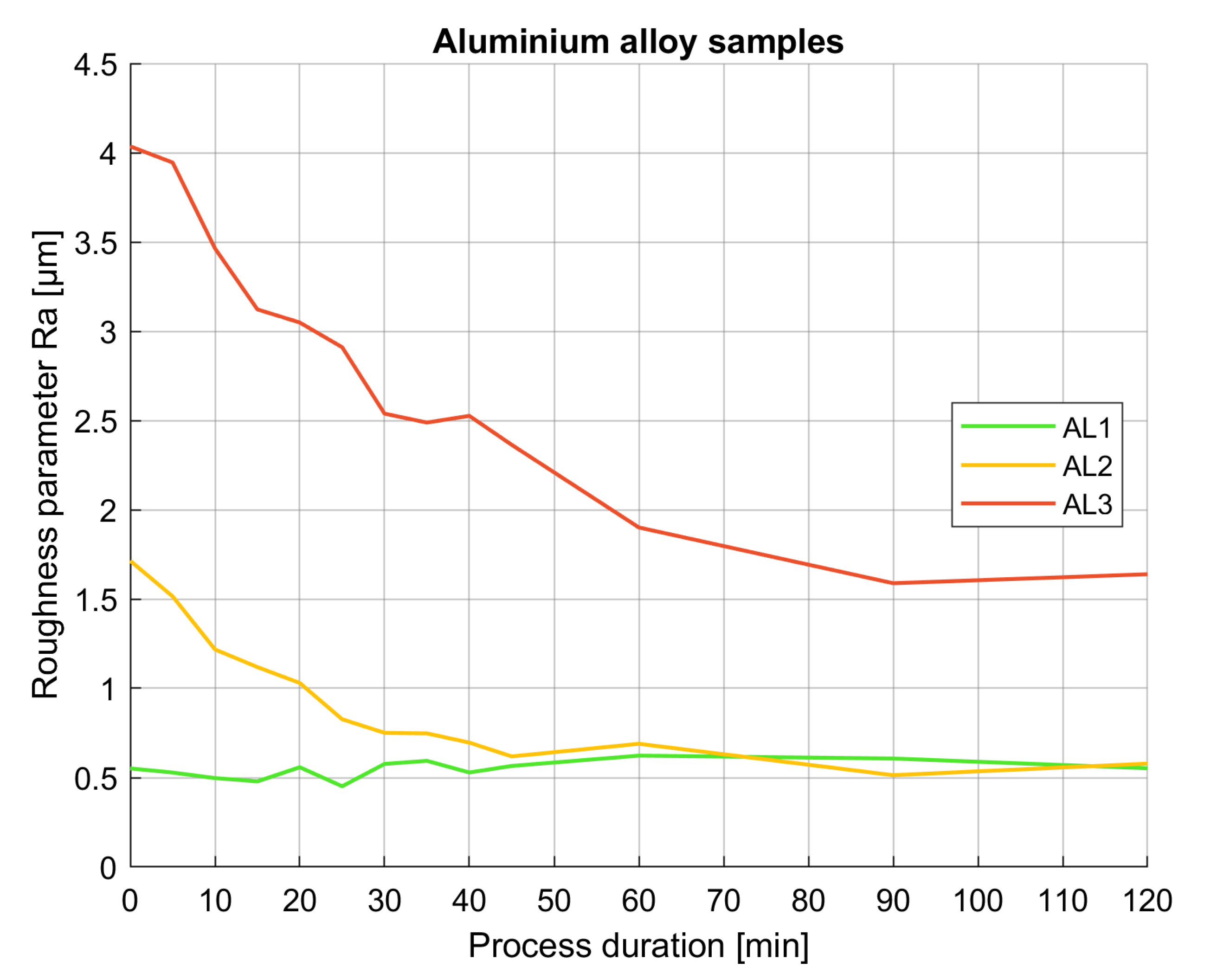
A considerable change in surface roughness was observed for two out of three processed samples made out of aluminum alloy. The higher the entry surface roughness, the steeper the change that occurred during the drag-finishing process. For the sample with the lowest entry roughness, practically no change was observed by the end of the process. The development of the averaged surface roughness parameter
Ra for all aluminum alloy samples is plotted in
Figure 3.
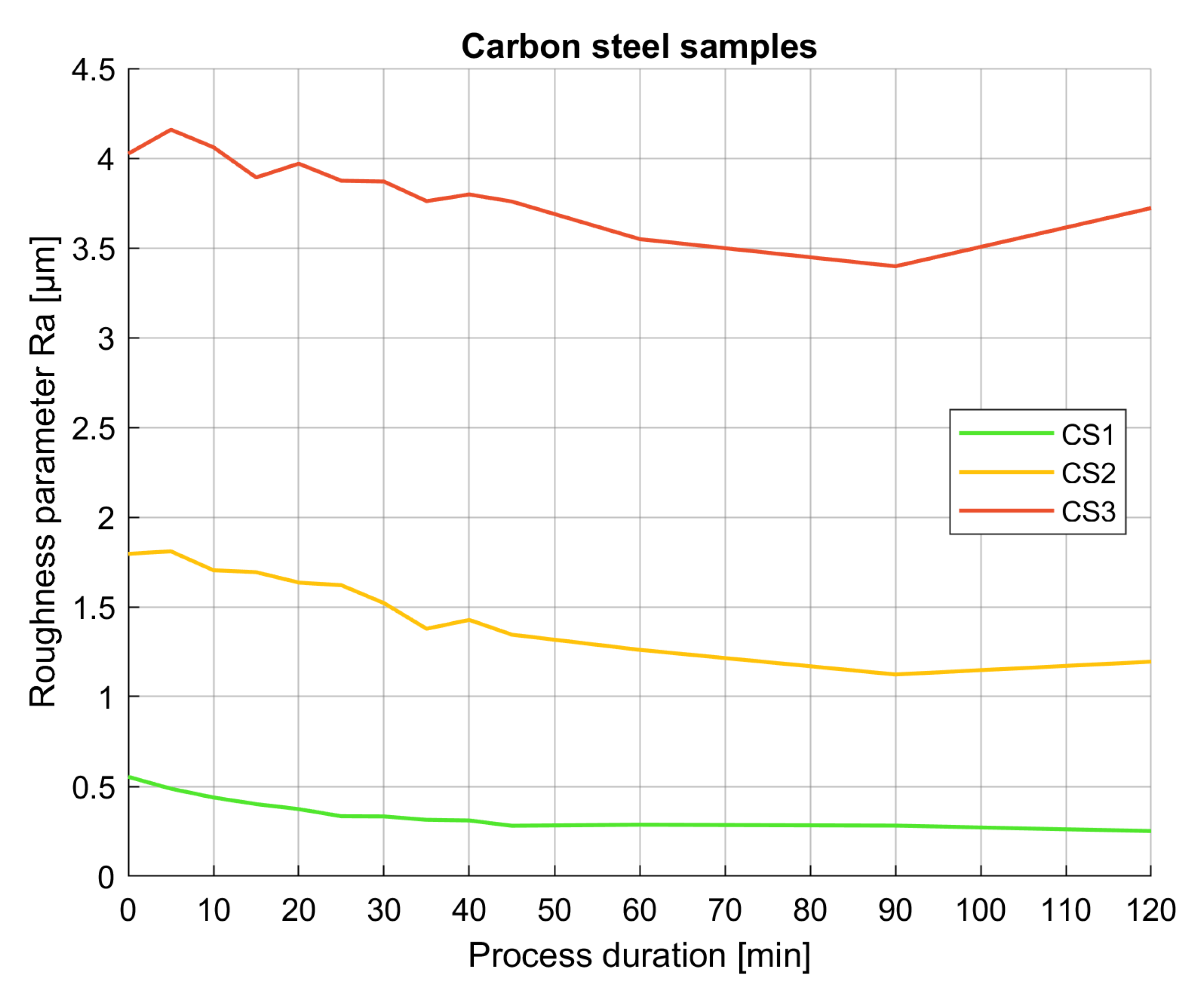
For carbon steel samples, the change in the surface roughness was not as steep as that for the samples made out of aluminum alloy, which is most likely caused by higher hardness of the material. However, the final surface roughness was an improvement for all three processed samples, as can be seen in
Figure 4. For samples 2 and 3, with higher initial surface roughness, it is worth noting that the final value of the surface roughness was not the lowest one observed throughout the process. At 90 min of processing time, the lowest values of surface roughness were observed, which slightly increased towards the end of the finishing process at 120 min.
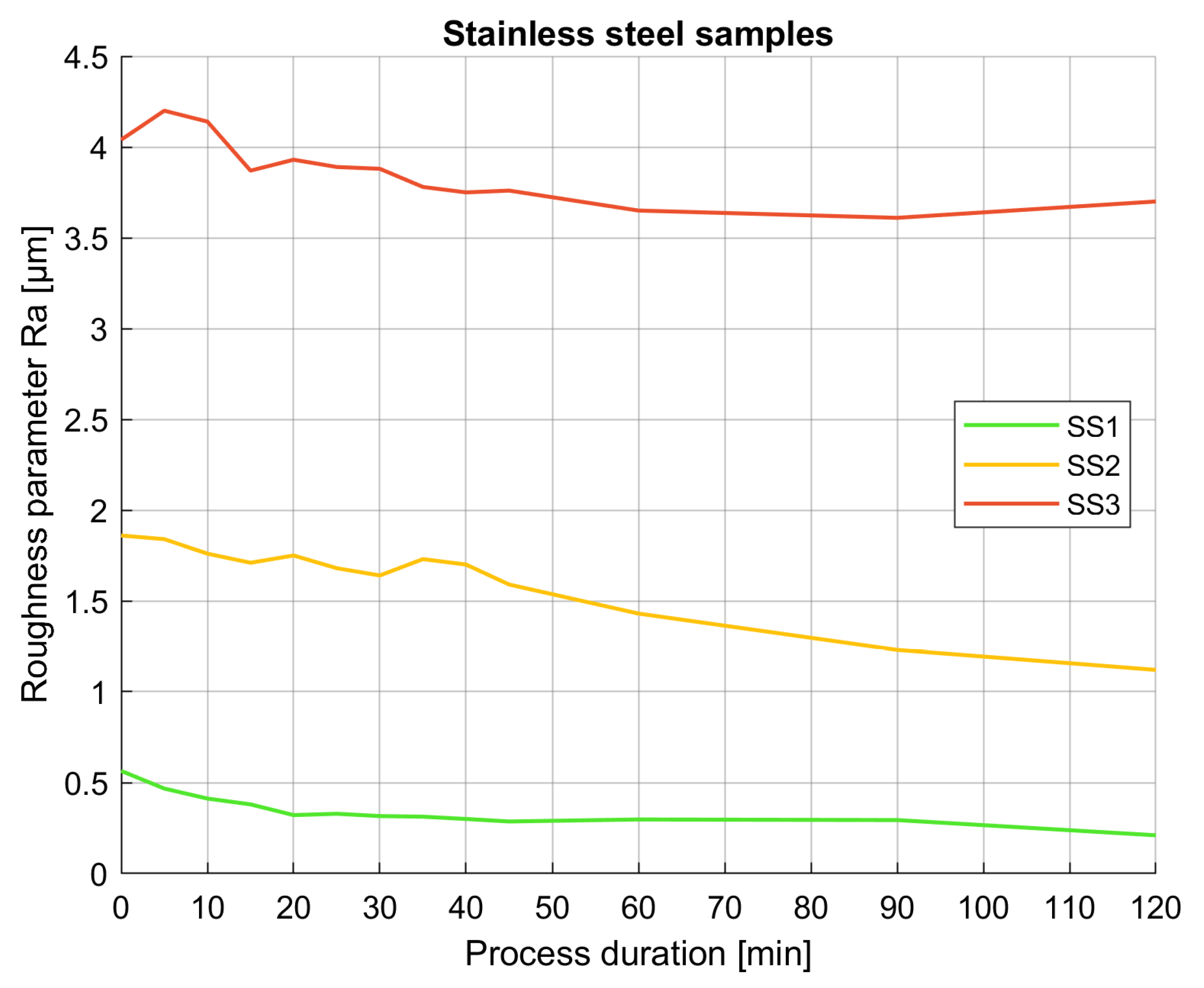
A reduction in the surface roughness parameter
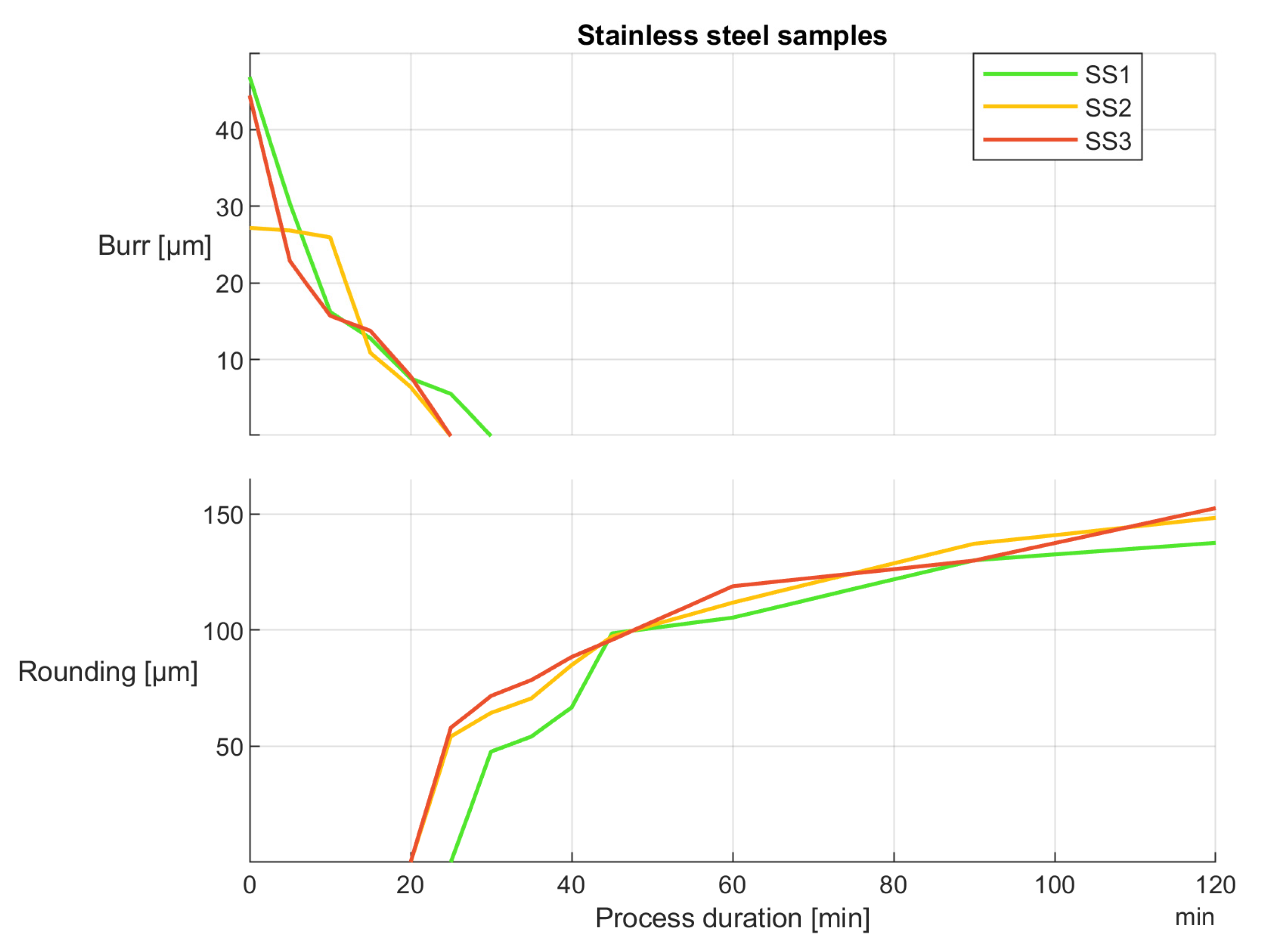
Ra was observed for all the samples made out of stainless steel as well. Both the roughness values by the end of the process and the overall character of the roughness development were comparable to the samples made out of carbon steel material. For the sample with the highest initial surface roughness, a very minor increase in surface roughness was also observed from the 90 to 120 min mark. This is illustrated in
Figure 5.
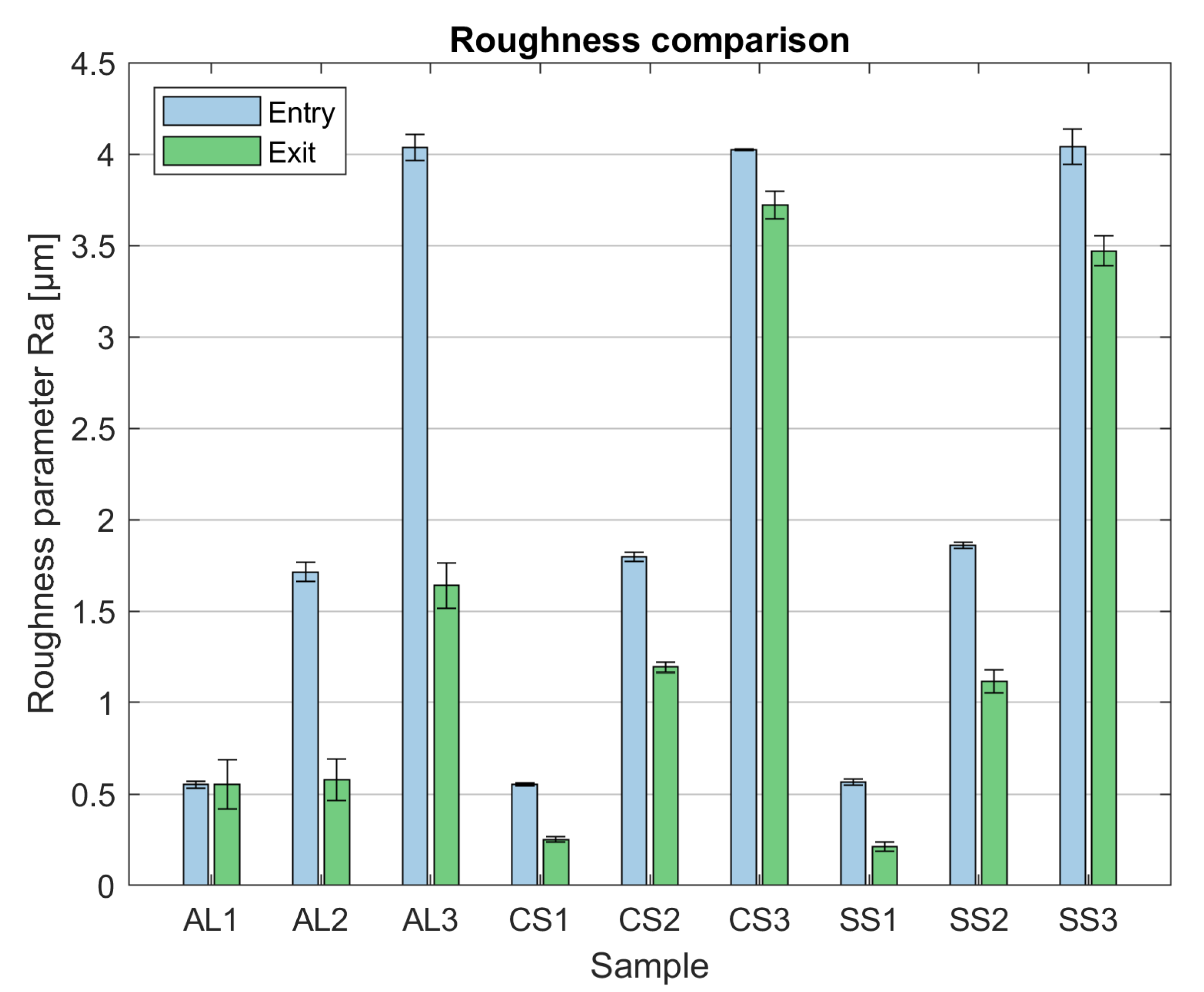
Observing the overall character of the surface roughness development for all nine samples, it can be stated that the most significant changes occurred in the first sixty minutes of the drag-finishing process and slowed down considerably for the remaining duration. The overall change in the sample roughness is listed in
Figure 6 for overview.
3.2. Dimensions
Changes in the dimensions of the samples were observed, specifically the diameter. The measurement was performed on three height levels to better evaluate the dimensional changes along the entire length of the samples and to determine the influence of immersion depth on the material removal rate. The removed material variable in the plots represents negative change in the workpiece’s diameter. The first level of measurement was three millimeters from the sample end, which translates to an immersion depth of 60 mm; the second level of measurement was 15 mm from the sample end, which corresponds to an immersion depth of 48 mm; and the third level of measurement was 27 mm from the end, representing 36 mm immersion depth. It is important to note that the immersion depth was not constant throughout the process because the finishing medium was not completely level, and its surface changed as a result of flow movement.
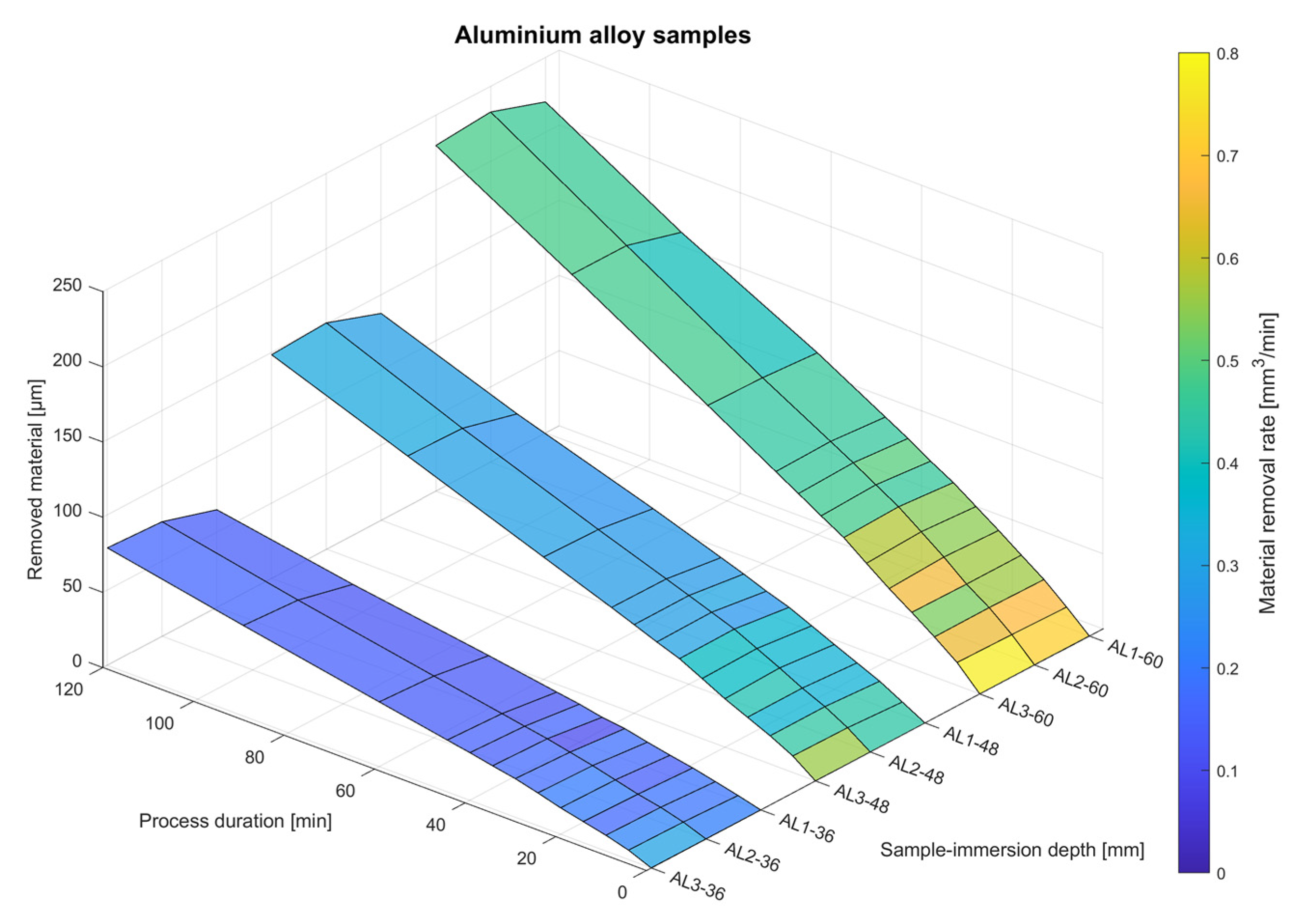
For the samples made from aluminum alloy, a considerable change in diameter was observed, as well as a higher rate of material removal compared to other materials used in the experiment. This was caused, most likely, by the lower hardness and density of the material. Immersion depth also plays a significant role in both the amount of removed material and the rate of its removal.
Figure 7 contains plotted values of dimensional changes represented as the accumulated amount of removed material.
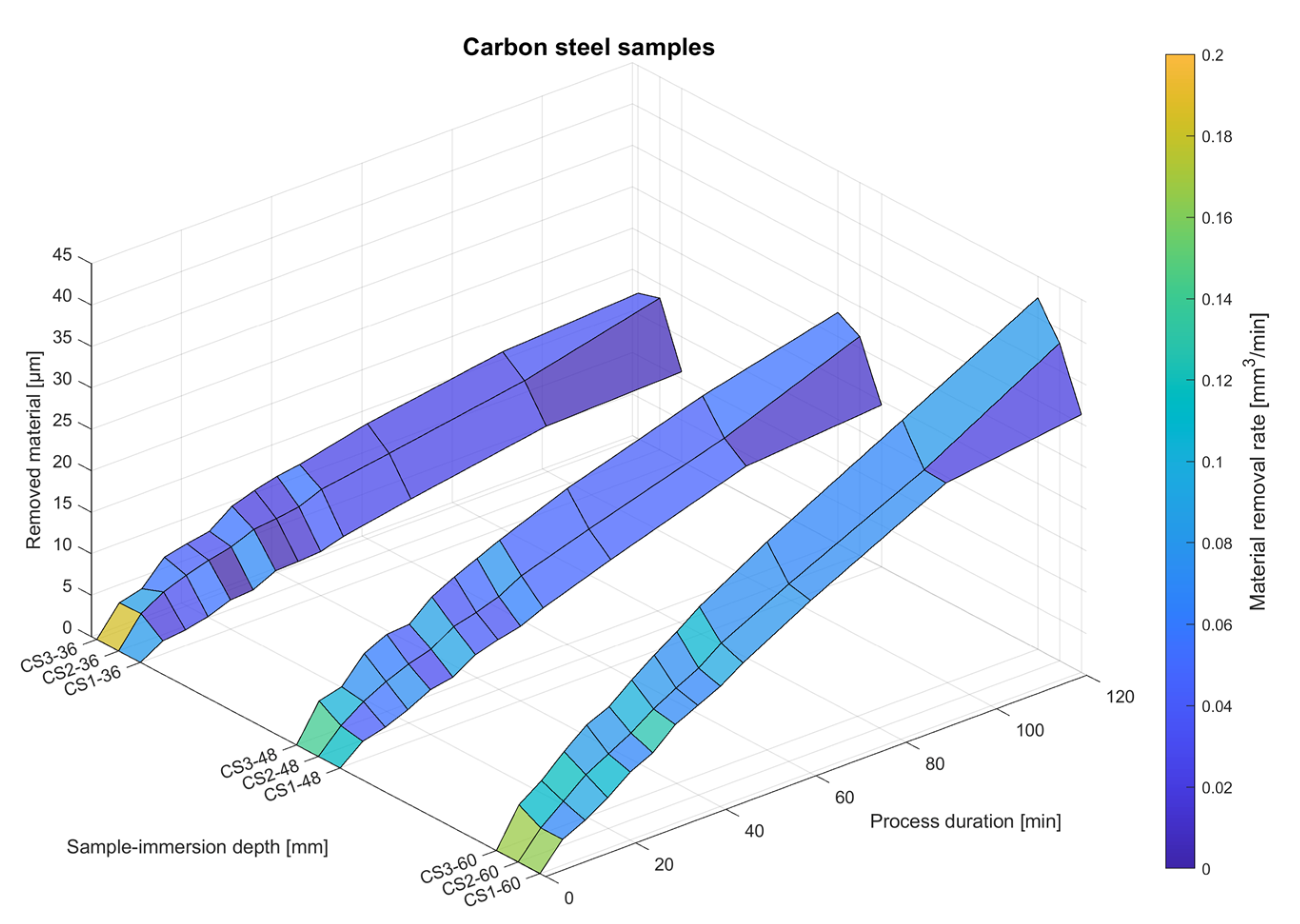
A change in the diameter dimension as a result of material removal was observed for the carbon steel samples as well, with the overall change being less substantial than for the aluminum alloy samples, as can be seen in
Figure 8. Note that the viewing angle is shifted for better readability. A higher immersion depth resulted in a greater dimensional change in the diameter, comparable to the aluminum alloy samples; however, the overall amount of removed material as well as the material removal rate were considerably lower. Moreover, the initial sample roughness apparently influences the material’s removal from the diameter in a different way compared to the aluminum alloy samples. Carbon steel samples with an initial roughness
Ra value of 0.5 µm showed a substantially increased amount of diameter reduction compared to the other samples with higher initial roughness values.
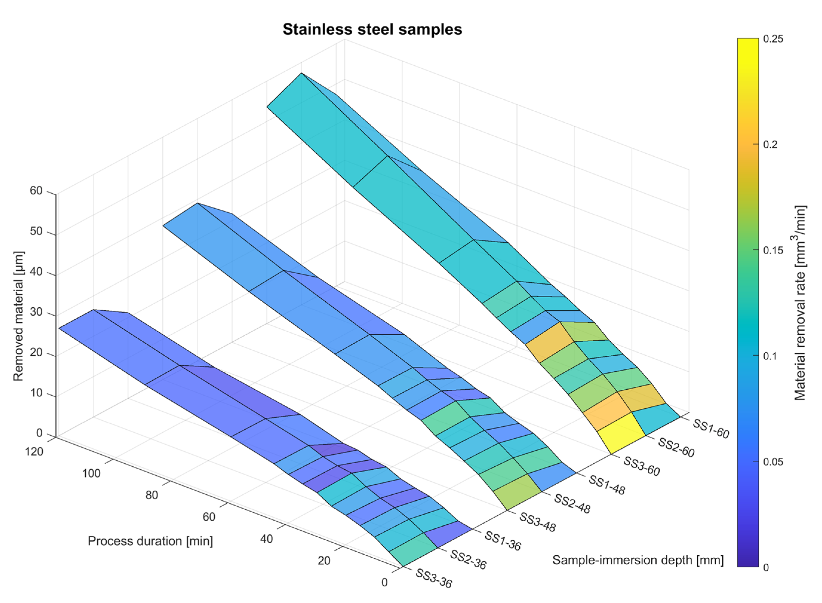
Samples made out of stainless steel showed similar character of material removal as the aluminum alloy samples, but with a much lower total amount of material removed as well as a much lower material removal rate. This can be seen in
Figure 9.
Considering the character of dimensional changes for all the samples, it can be stated that the most rapid removal of material from the diameter of the samples occurred at the beginning of the process and was significantly influenced by the immersion depth throughout the drag finishing. Averaged dimensional changes are listed in
Figure 10.
3.3. Deburring and Edge Rounding
Another observed characteristic of the samples was the size of the burr and subsequent rounding of the edge. In order for the edge rounding to be formed, first, the burr on the edge resulting from machining had to be completely removed. Edge rounding formation was considerable during the first 45 min of the process.
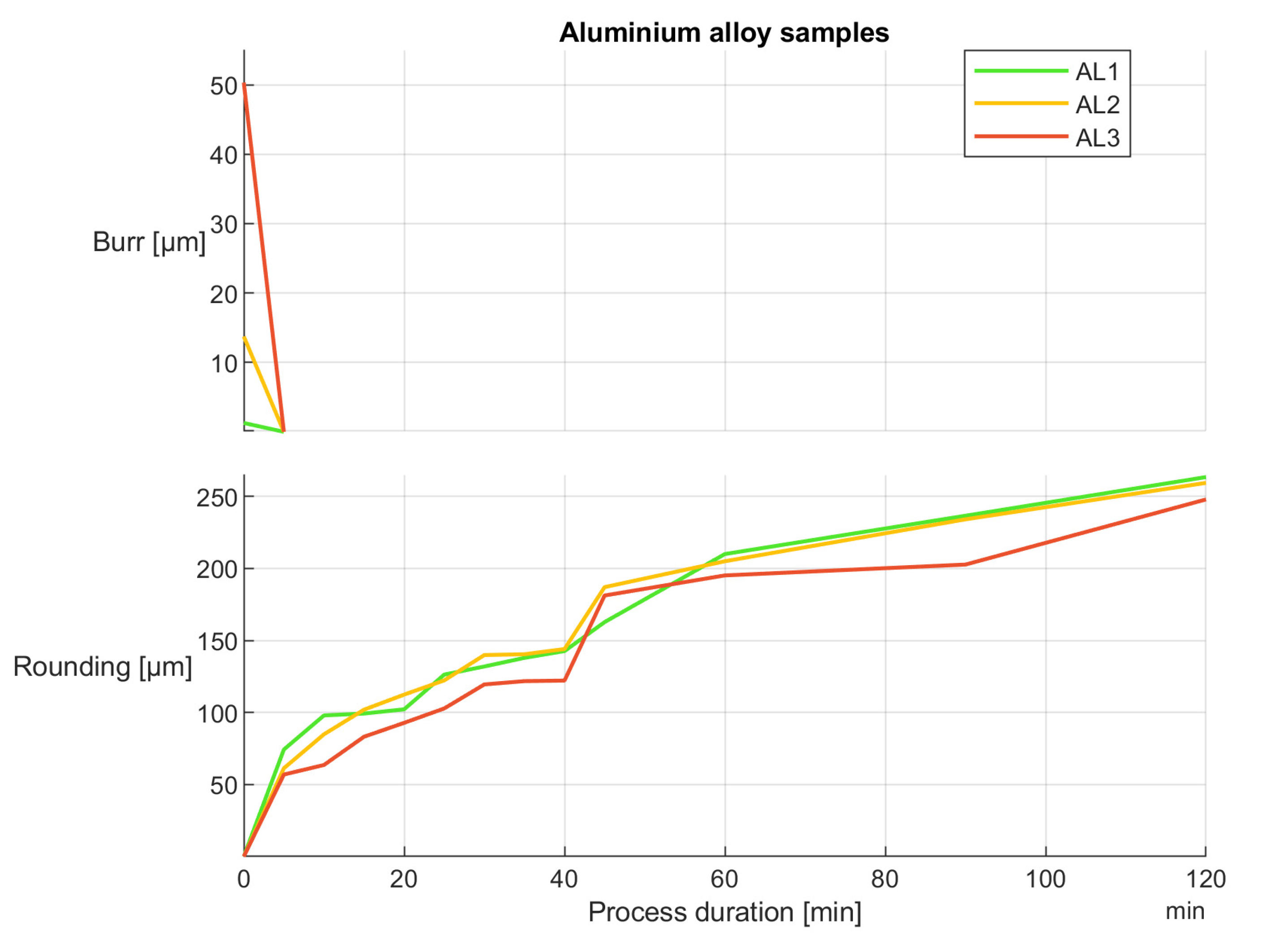
For aluminum, samples the burr on the edge was removed within first five minutes of drag finishing, as can be seen in
Figure 11. Subsequent edge rounding development had a non-linear character, with the most substantial changes happening in the beginning of the drag-finishing process.
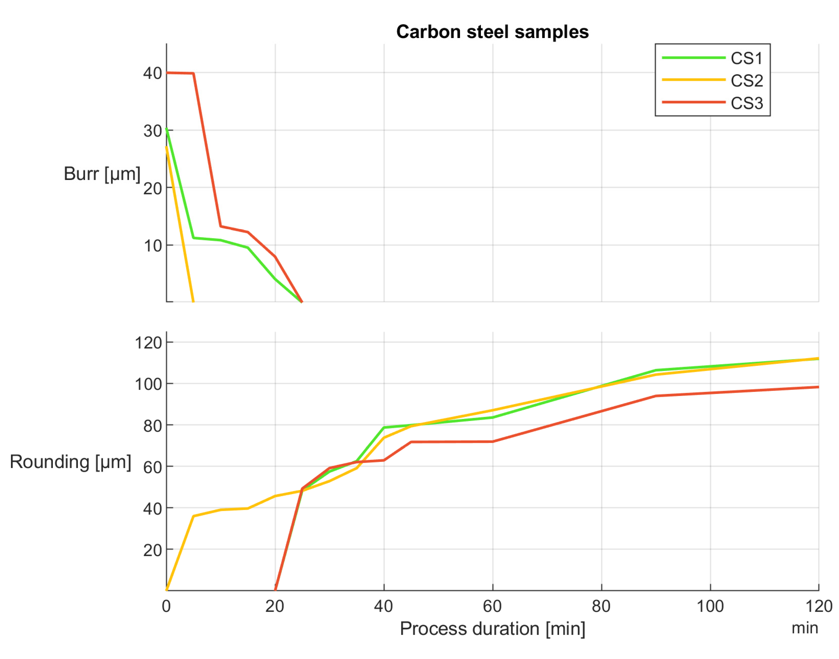
For carbon steel, it took almost quadruple the amount of time to remove the edge burr, and the formation of edge rounding also took longer than it did for the aluminum samples. Moreover, the size of the final edge rounding was considerably lower than in the aforementioned samples, as is displayed in
Figure 12.
Stainless steel samples showed similar deburring and edge rounding formation as the samples made of carbon steel, with slightly larger edge rounding radii by the end of the process. This can be observed in
Figure 13.
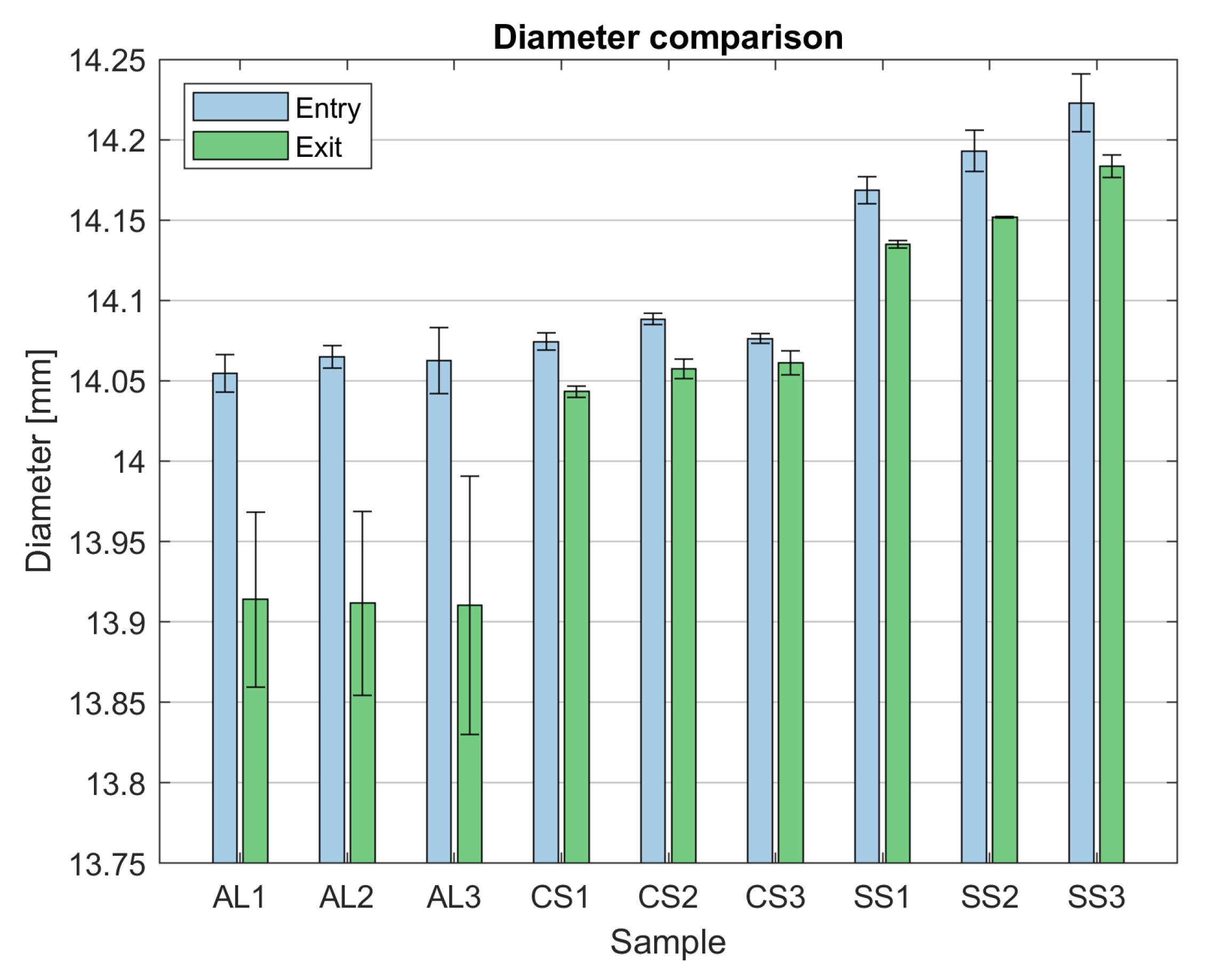
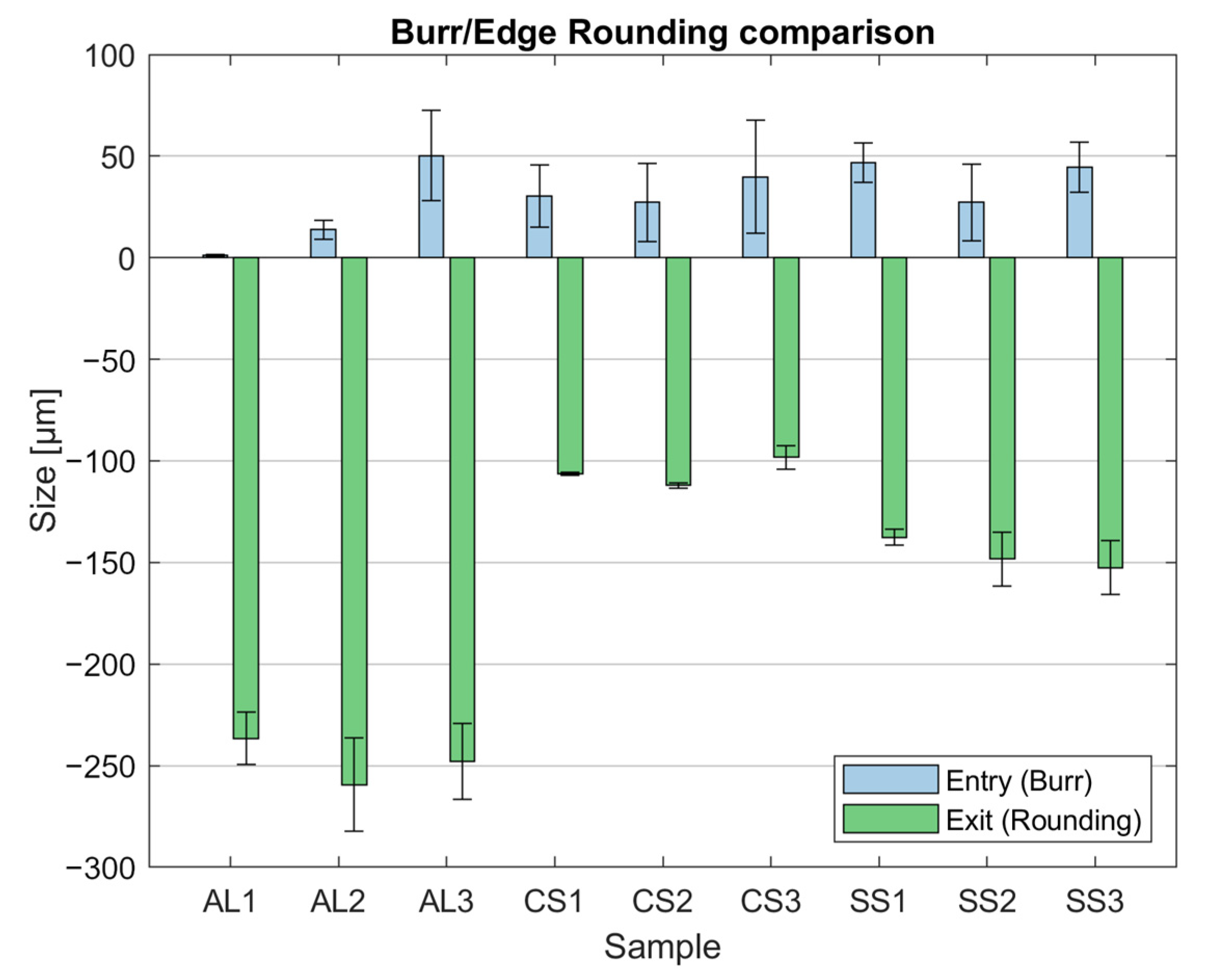
The biggest changes occurred in the samples with the highest surface roughness and, therefore, also the largest burr on the edge of the machined surface. Not only was the largest burr removed in a comparable amount of time to a smaller burr, but the resulting size of the edge rounding was also comparable to the samples with better surface roughness and smaller burrs. A comparison of the burr size at the beginning of the drag-finishing process and the edge rounding at the end of the process is listed in
Figure 14. Note that, while the edge rounding values are plotted on the negative axis, they still represent the size of the edge rounding.
4. Discussion
The results of the roughness measurement indicate an influence of both the sample material and the initial roughness on the outcome of the drag-finishing process. For aluminum alloy samples, higher initial roughness values led to more significant reductions in surface roughness; however, the lowest roughness value remained unchanged. This was most likely caused by strain hardening of the surface layer and is consistent with the results described by Malkorra [
21]. Conversely, carbon steel and stainless steel samples exhibited smaller changes in surface roughness, with variations attributed to differences in material hardness, but with a consistent reduction in surface roughness for all samples. Similar results were observed again by Malkorra [
15]. Furthermore, the stainless steel samples showed roughness changes similar to those of carbon steel, indicating a comparable surface refinement despite the considerable difference in material composition. These findings emphasize the importance of taking into account the material’s properties and initial surface conditions when utilizing the drag-finishing process to achieve the desired surface quality results in manufacturing applications.
Across all material categories, a diameter reduction in the workpieces was observed as a result of material removal during the drag-finishing process. Measurements at different height levels of the samples indicated variations in material removal rates influenced by immersion depth, as is similar to the experiments carried out by Hronek [
27]. However, variations in the magnitude of diameter change were also noted between different materials, with carbon steel samples exhibiting the smallest changes and aluminum alloy samples experiencing the most substantial reductions. These results emphasize the importance of taking into account the material properties of workpieces processed by drag-finishing to obtain the desired dimensions and tolerances, since they show that the materials with lower hardness can undergo changes of dimensions on the order of a tenth of a millimeter or more. Overall, the observed changes in diameter underscore the dynamic dependence between material properties, immersion depth, and initial roughness, influencing dimensional changes and material removal rates during the drag-finishing process.
Considering the deburring application, it is apparent that the initial size of the burr plays a significant role in determining the extent of edge rounding achieved after the drag-finishing process, as was also confirmed by Kim [
28]. Smaller initial burr sizes tend to result in larger edge radii by the end of the process, indicating more pronounced edge rounding. Conversely, larger initial burrs may require longer processing times to be completely removed, potentially resulting in smaller edge radii and less prominent edge rounding. Therefore, reducing the initial burr size appears to be a contributing factor to achieving larger edge radii and smoother edge profiles during drag finishing.
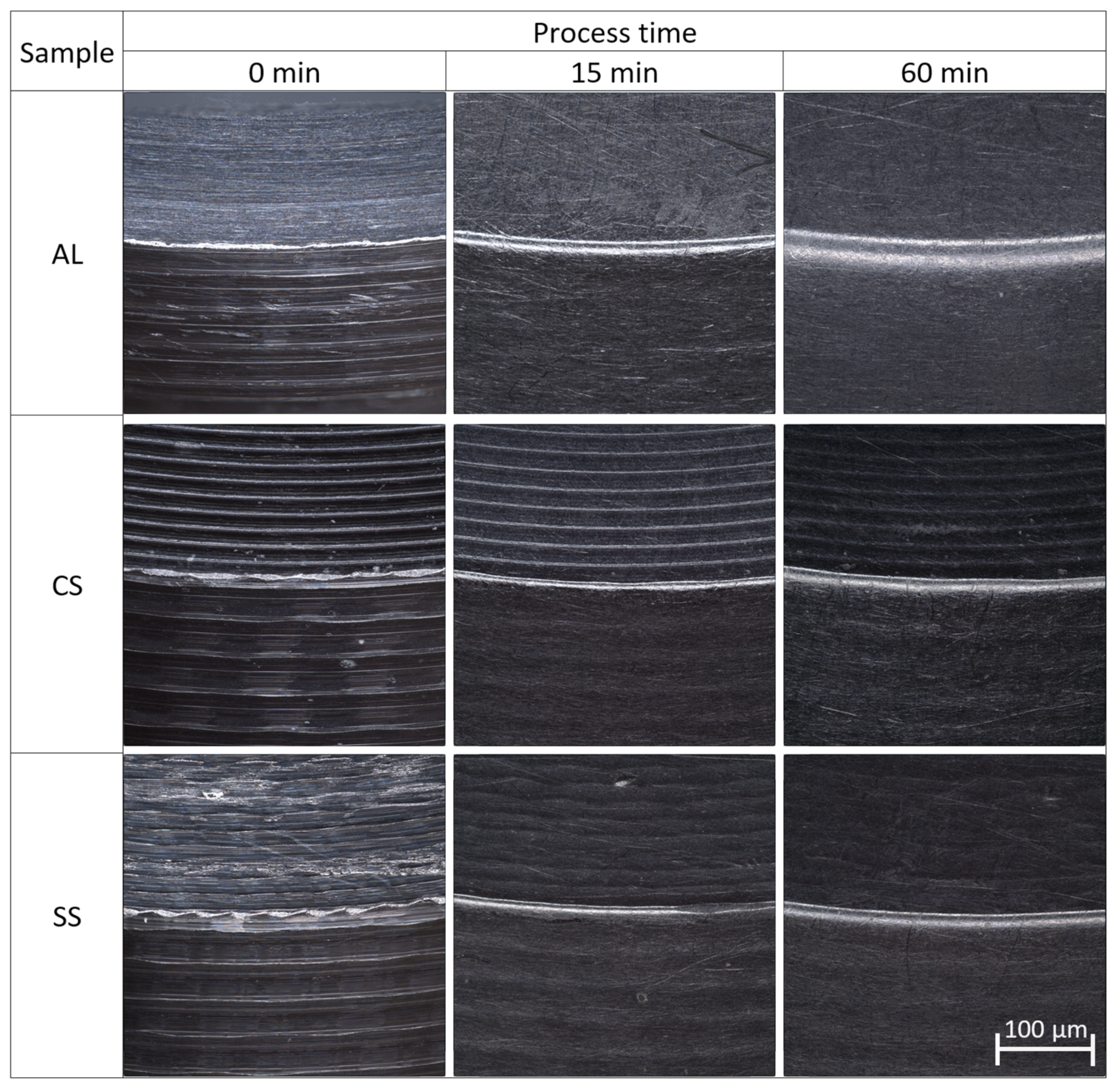
The detailed development of the surface states of samples with initial roughness values of
Ra = 1.75 µm for up to 60 min of processing time is illustrated in
Figure 15. The images in the figure were captured at the measurement point, as indicated in
Figure 1. It can be seen in the figure that only for the samples made of aluminum alloy was complete removal of the surface profile resulting from the machining operation achieved. Moreover, this smoothing effect was observed quite early in the process, after about 15 min. This explains why the aluminum alloy samples 2 and 3 showed the most prominent reductions in the parameters of surface roughness. For both carbon and stainless steel samples, the surface profile was reduced but not completely removed, resulting in comparably lower reductions in the surface roughness parameters for these samples.
The aim of the experiment described in the paper was to verify whether the prototype drag-finishing machine for hard metal tools can be used for the controlled processing of general workpieces. As can be seen from
Table 7, where the differences between the initial and final values of all measured workpiece properties are listed, this goal was accomplished. Using constant process parameters, an improvement in surface roughness, burr removal, and edge rounding was observed for all workpieces. It should be pointed out that the finishing media used was not sufficiently effective at removing surface irregularities in the form of peaks resulting from the machining process; therefore, it was not possible to achieve lower roughness of the surface. For steel materials, there was a comparably lower reduction in surface roughness due to the finishing medium, which merely copied the surface profile without much smoothing of the entire surface. For the AL3 sample, there was a considerable reduction in the surface roughness compared to all other samples used for the experiment. The material removal mechanism was the same as for the rest of the samples; however, the hardness of the aluminum alloy used was much lower than that of the steel materials, which caused a more prominent change in the surface roughness. Changing the type of finishing media or process parameters is going to influence the outcome of drag finishing with regard to the workpiece properties achieved as well as the processing time. Therefore, it is important to adjust the parameters of drag finishing on the prototype machine in order to obtain desirable workpiece properties.
5. Conclusions
This article investigated the process of controlled drag finishing of generic workpieces, since achieving high quality of a workpiece surface finish regardless of the material and technology that are used for manufacturing is a desirable goal for the production of a wide variety of industrial parts. However, obtaining and operating machines for the purpose of surface modification can be economically and technologically challenging. Using one type of machine designed for multi-purpose drag finishing of both cutting tools from hard metals and general workpieces from a wide range of common materials has certain benefits from the standpoint of company budget, physical space, and operator load. The experiment described in this paper was performed with the goal of verifying the feasibility of using a prototype high-speed drag finishing machine for processing generic workpieces from a range of commonly used materials.
The results of the experiment have produced the following findings regarding the drag-finishing process of generic workpieces from various materials:
A drag-finishing machine designed primarily for tool microgeometry modification can be successfully and reliably used for workpiece modification if the clamping solution permits;
The surface state of the workpiece influences the material removal rate—the higher the initial surface roughness, the higher the material removal rate;
For aluminum alloy materials, or materials with comparable hardness properties, the drag-finishing process can influence the dimensional characteristics of the workpieces significantly, possibly interfering with dimensional tolerances;
The time required for burr removal depends on the material properties—the shortest processing time to remove burrs after machining was 5 min for aluminum alloy, and the longest was 30 min for stainless steel samples;
The immersion depth of the samples has a significant impact on the material removal rate.
The process time required to achieve sufficient surface properties can be reduced substantially depending on the target surface roughness.
The proposed high-speed drag finishing machine offers several advantages compared to other widespread finishing methods such as abrasive blasting, vibratory finishing, and barrel finishing. The process requires shorter processing times while achieving comparable results compared to other methods. The continuous movement of the workpieces through the finishing media allows for rapid material removal and the modification of surface characteristics. This results in higher productivity and shorter production cycles. Moreover, it provides a consistent and uniform surface finish across all treated parts, within reasonable limitations of the shape complexity. The pattern of movement of the workpieces ensures that each component is exposed to the finishing media for an equal duration, resulting in uniform surface characteristics without localized surface damage, which can often happen with other finishing methods. The process is highly versatile and adaptable to a wide range of workpiece materials, shapes, and sizes. Additionally, various types of finishing media can be employed to achieve surface states according to specific requirements. Switching of the media container takes a short amount of time and is tool-free. One of the major advantages of the proposed drag-finishing process is that it allows for precise control over process parameters such as the process time, rotational speed, direction of rotation, immersion depth, and workpiece angle, enabling consistent quality in the results.
Even though the experiment was considered a success with regard to the outcome of the workpiece processing, there still remain challenges to be solved, such as:
Clamping issues for workpieces with more complicated shapes, which require dedicated fixtures;
A limited number of workpieces; the maximum number of workpieces able to be processed simultaneously is 15 at the present time. This point is closely related to the previous one, since the number of workpieces could be increased by utilizing different means of clamping;
Media depreciation due to limited volume of media in the finishing container and high material removal rate of the workpieces;
Non-uniform immersion depth, resulting in uneven material removal from the workpieces.
Solving these issues will be the main focus of further development of the prototype machine from the standpoint of workpiece finishing and subsequent experiments.


 ,
, 


