Article

Investigation of Force-Controlled Polishing of Complex Curved PMMA Parts on a Machining Center

State Key Laboratory of High-Performance Precision Manufacturing, School of Mechanical Engineering, Dalian University of Technology, Dalian 116024, China
*
Author to whom correspondence should be addressed.
Machines 2024, 12(4), 259; https://doi.org/10.3390/machines12040259
Submission received: 19 March 2024 / Revised: 9 April 2024 / Accepted: 11 April 2024 / Published: 14 April 2024
(This article belongs to the Special Issue Machine Tools for Precision Machining: Design, Control and Prospects)

Abstract

:
During the polishing process of complex curved PMMA parts, the polishing force is an important factor affecting the surface quality and optical performance. In this paper, a force-controlled polishing device integrated into a machining center to maintain the polishing force is investigated. In order to achieve the real-time active control of the polishing force, the linear voice coil motor and force sensors are used for motion and measurement. A compact structure was designed to couple the linear motion of the voice coil motor with the rotation for polishing. The force-controlled polishing system with a high real-time hardware architecture was developed to perform complex curved polishing path movement with precise force control. Next, the polishing force between the device and the workpiece was analyzed to obtain the mathematical model of the device. Considering the impact during the approaching phase of polishing, a fuzzy PI controller was proposed to reduce the overshoot and response time. To implement the control method, the controller model was established on Simulink and the control system was developed based on TwinCAT 3 software with real-time computing capability. Finally, a polishing experiment involving a complex curved PMMA part was conducted by a force-controlled polishing device integrated into a five-axis machining center. The results show that the device can effectively maintain the polishing force to improve surface quality and optical performance.

1. Introduction

Due to its high level of transparency and specific strength, poly methyl methacrylate (PMMA) is widely used in aerospace, the automotive industry, electronic instruments, construction, and other fields. However, the optical performance of PMMA is severely affected by surface quality [1,2]. Machining operations such as milling frequently result in heightened cutting forces and vibrations, thereby degrading the surface quality [3,4]. Although, in the polishing process, it is difficult to correct the profile errors caused by the milling process, this process can significantly reduce the surface roughness and improve the surface quality. Therefore, polishing, as the final step in the high-performance machining of complex curved PMMA parts, can significantly improve surface quality and optical performance. Conventionally, due to the fact that they are easy to damage and to their temperature sensitivity, PMMA parts are often polished by manual operations, which is time-consuming, costly, and strictly dependent on the skills of the operator. In recent years, studies on polishing complex curved parts have attracted the interest of scholars for the purpose of polishing machines or robot-polishing system instead of the conventional manual polishing process.
For the polishing of complex curved parts, scholars have conducted studies concentrating on polishing equipment and systems [5,6,7], polishing tool design [8,9,10,11,12,13], toolpath patterns [12,13], and process parameter optimization [14,15]. For example, Xu et al. [5] developed a parallel polishing machine with a five-DOF parallel manipulator and a force feedback system to improve the roughness of surfaces. Yong et al. [10] optimized the deformation layer of a polishing pad by the finite element simulation of the contact area, which improved the surface quality of a complex curved aluminum alloy mirror. A trochoidal toolpath was proposed by Xu et al. [13] to keep the consistency of the material-removal distribution. Research on polishing parameter optimization for complex curved surfaces was presented by Chen et al. [15] to derive an optimized process parameter model. Undoubtedly, these studies provide innovative tools and theoretical foundations for the polishing of complex curved parts. Moreover, the mutual and pivotal concept in these studies is keeping the uniformity of the removal effect by maintaining a constant interaction between the polishing tool and the workpiece, which is critically affected by the polishing contact force. For PMMA parts, maintaining a constant contact force between the polishing tool and the parts is essential to prevent burn damage and to avoid excessive or insufficient polishing. Implementing real-time force control is crucial in the polishing process for complex curved PMMA parts.
Currently, two prevalent methods of force control are employed for the polishing of complex curved parts. The first method controls the polishing force by adjusting the movement of the multiaxial equipment executing the curved surface path, as in five-axis machining centers or industrial robots [16,17]. Due to the lack of an interface for users to arbitrarily modify the control algorithms of multiaxial equipment, some studies can only correct the path of the next polishing cycle through the feedback of the force sensor [18]. To control the polishing force in real time, Kakinuma et al. [19,20,21,22] proposed a novel methodology based on the sensorless force control technique, and a serial–parallel polishing machine was designed with a force control method for unknown curved surfaces. To achieve more accurate force control during the polishing process for curved surfaces, Tian proposed a position correction method involving a robot with a force sensor and a gravity compensation algorithm for stable force feedback [23,24]. However, multiaxial equipment commonly has a large amount of inertia and considerable friction in the transmission system, which leads to poor force control performance. The second method uses an external device to perform force control [17]. Multiaxial equipment executes curved path movement while an external device performs force-controlled polishing. Although the structure of the polishing system becomes more complex with this method, each part retains advantages in operations. The external device has high bandwidth and low impedance [25], while the multiaxial equipment has a large workspace. This method is often used in robot polishing systems [26,27,28] for the control of polishing force. Yu and Zhang [29,30] have developed active force-controlled robot polishing systems with external devices for complex curved PMMA parts. These devices use a motor or cylinder as the drive and achieve real-time active control through the feedback value of the force sensors. However, industrial robots exhibit characteristics of strong coupling and nonlinearity, which result in motion errors and vibrations. These issues reduce the stability of the force control during the polishing process.
The integration of force-controlled polishing devices into machining centers enables a reduction in vibration errors and an increase in control frequency for precise control performance. To achieve a force control device integrated into the machining center, Grochala et al. [31] designed a micro-hydraulic tool that utilizes the hydraulic system of the machining center for force control. Furthermore, a method of combining shaping and finishing on a machining center in one operation was proposed to decrease the roughness height and improve optical performance [32]. Although this device can actively control the contact force between the tool and the workpiece in real time, it lacks the ability to perform rotary polishing and is limited to ball burnishing. Mitropoulos et al. [33] developed a polishing device that uses springs for force control. This device rotates by an external spindle, making the machining center’s own spindle redundant. This structure increases inertia, and the passive control of the springs has poor accuracy for polishing. Consequently, current force control devices that are integrated into machining centers fail to provide the real-time, active, and accurate force control required for the polishing of complex curved PMMA parts.
For the polishing of complex curved PMMA parts, a force-controlled polishing device integrated into a machining center is investigated in this paper. In Section 2, a low-inertia and high-response-frequency structure is presented. The force-controlled polishing system with a real-time hardware architecture was developed to perform complex curved polishing path movement with precise force control. Considering the approaching phase of the polishing process, a fuzzy PI controller is proposed in Section 3, and the implementation of the control method is introduced. Next, polishing experiments involving complex curved PMMA parts are reported in Section 4. Finally, the conclusions are given in Section 5.

2. Structure of Force-Controlled Polishing Device and Development of Polishing System

2.1. Structure of Force-Controlled Polishing Device

In order to implement the force-controlled polishing of complex curved PMMA parts on the machining center, a device was designed with ability of force control and rotation, which are required in polishing. The structure of the force-controlled polishing device is shown in Figure 1. The device performs force-controlled polishing with low inertia, while the five-axis machining center executes the curved path movement with a large workspace.
The force-controlled polishing device is designed to be installed on the spindle of the machining center with a tool handle and an installation flange. A linear voice coil motor is used as the electromagnetic motion component, which can generate a push or pull force proportional to the current in the coil. The linear voice coil motor simplifies the device structure to achieve high-response motion for force control. Linear bearings and springs, installed parallel to the motor, are used for guidance and support to increase the stability of the device. The compact and stable structure offers benefits in reducing the impact and vibration during the polishing process, consequently improving the control accuracy of the polishing force. Meanwhile, the device adopts a flexible foam pan with sandpaper as the polishing tool to conform the profiles of complex curved parts with varying curvature radii to provide a more consistent and evenly distributed polishing force. A linear encoder is used to measure the axial position of the voice coil motor. The force sensor is installed under the voice coil motor as a feedback component. High precision and high sampling frequency of the force sensors facilitate precise closed-loop control and reduce the control cycle for maintaining the desired force during polishing. To couple the rotational and linear motions required for force-controlled polishing, a rotary ball spline is used as the motion coupling component. The compact structure of the rotary ball spline enables the device to couple the rotation transmitted by the transmission shaft from the spindle and the linear motion generated by the LVCM simultaneously. The strong and stable power of the spindle is used for the rotation of the polishing tool. This compact structure reduces the mass of the motion structure, allowing lower inertia and higher response frequency from the device. The parameters of the device are shown in Table 1.

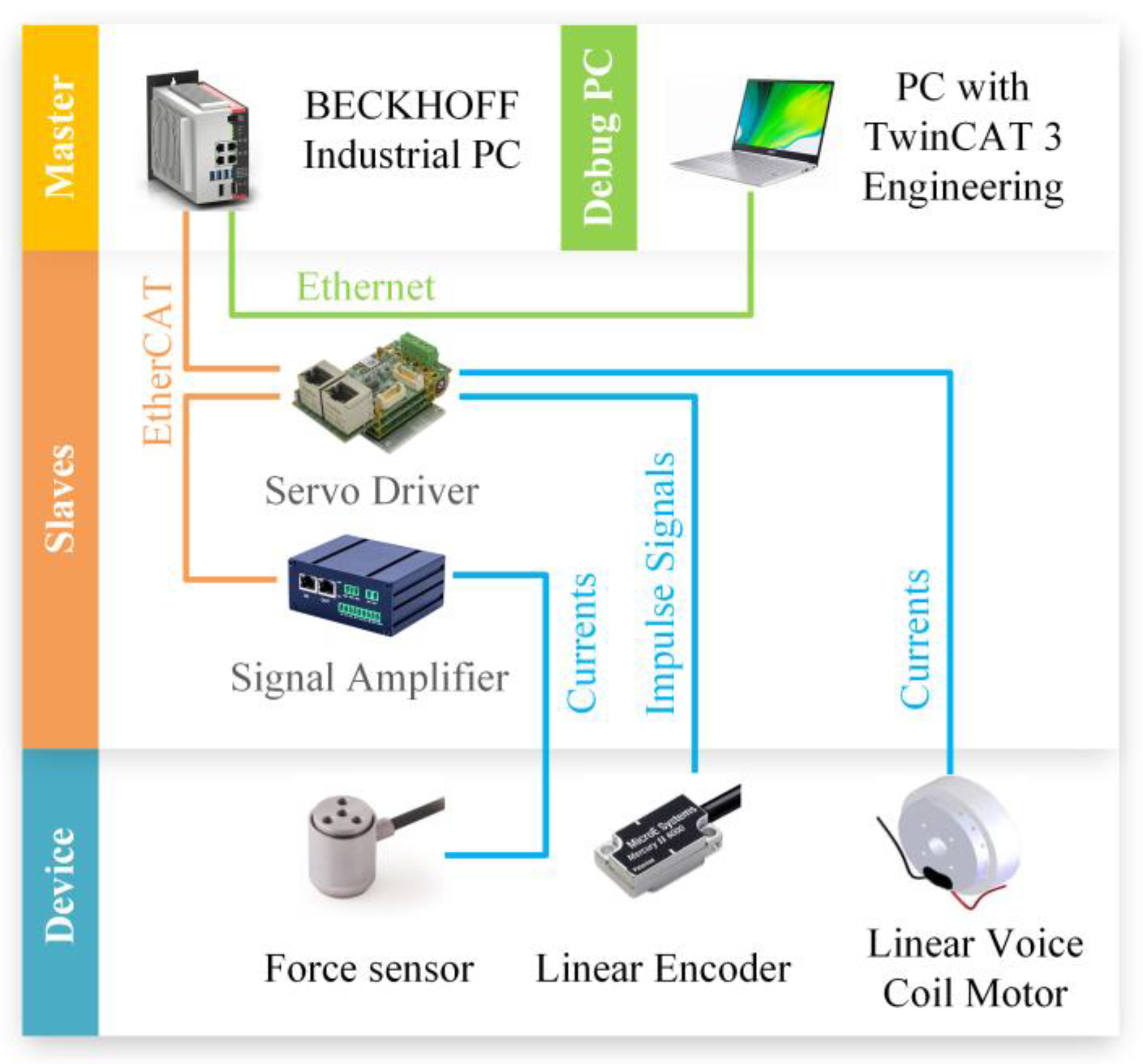
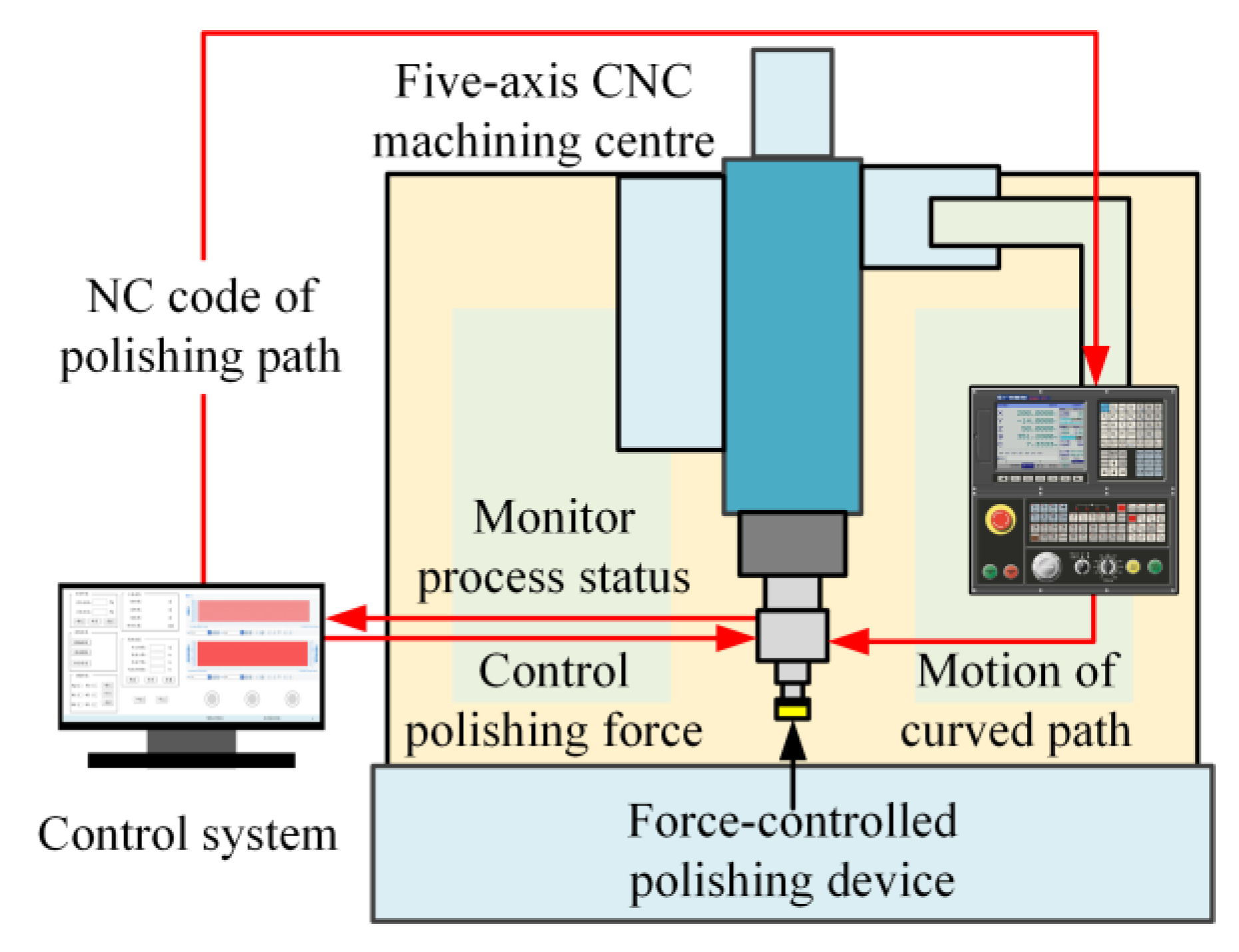
2.2. Development of Polishing System on Machining Center

To be able to drive the device, the hardware architecture of the force control system is designed with an industrial PC (IPC), a servo driver, and a signal amplifier, as shown in Figure 2.
The hardware architecture is crucial in a system, directly influencing system performance, reliability, and scalability. The hardware architecture is based on EtherCAT communication and master–slave structure, which seamlessly integrates with slave terminals to eliminate the need for additional specialized hardware. The master–slave structure and distributed clock synchronization technology of EtherCAT enable highly efficient data transmission in the network, facilitating low communication latency to meet the real-time requirements of force-controlled polishing. This integration reduces system costs and enhances overall performance [34,35,36]. The first component of the hardware architecture, referred to as the master, comprises an industrial PC serving as the central control device in EtherCAT master–slave communication. Additionally, another PC equipped with TwinCAT 3 Engineering software connects to the industrial PC through an Ethernet cable to execute programming and debugging tasks for the control system. The other components, referred to as slaves, comprise EtherCAT terminals connected to the device, which function as input/output (I/O) devices for communication and data acquisition. The device component integrates a linear voice coil motor and sensors within the force-controlled polishing device to measure and generate force.
Next, we developed a force-controlled polishing system, which involves the five-axis CNC machining center, the force-controlled polishing device, and the control system. Figure 3 illustrates the operational workflow of the force-controlled polishing system. Initially, the IPC of the control system generates the polishing-path-based model of the complex curved PMMA workpiece and dispatches the NC code of the polishing path to the machining center. Subsequently, the force-controlled polishing device, installed on the spindle of the machining center, follows the complex curved polishing path and performs the force-controlled polishing with rotation of the spindle. Meanwhile, the control system monitors the status of the polishing process through sensors and controls the polishing force between the device and the complex curved PMMA part. Consequently, the force-controlled polishing system can perform complex curved-polishing-path movement with precise force control. The stable control of polishing force ensures the consistency of roughness, thereby improving the surface quality and optical performance of complex curved-surface PMMA parts.

3. Modeling of Polishing Force and Implementation of Fuzzy PI Controller

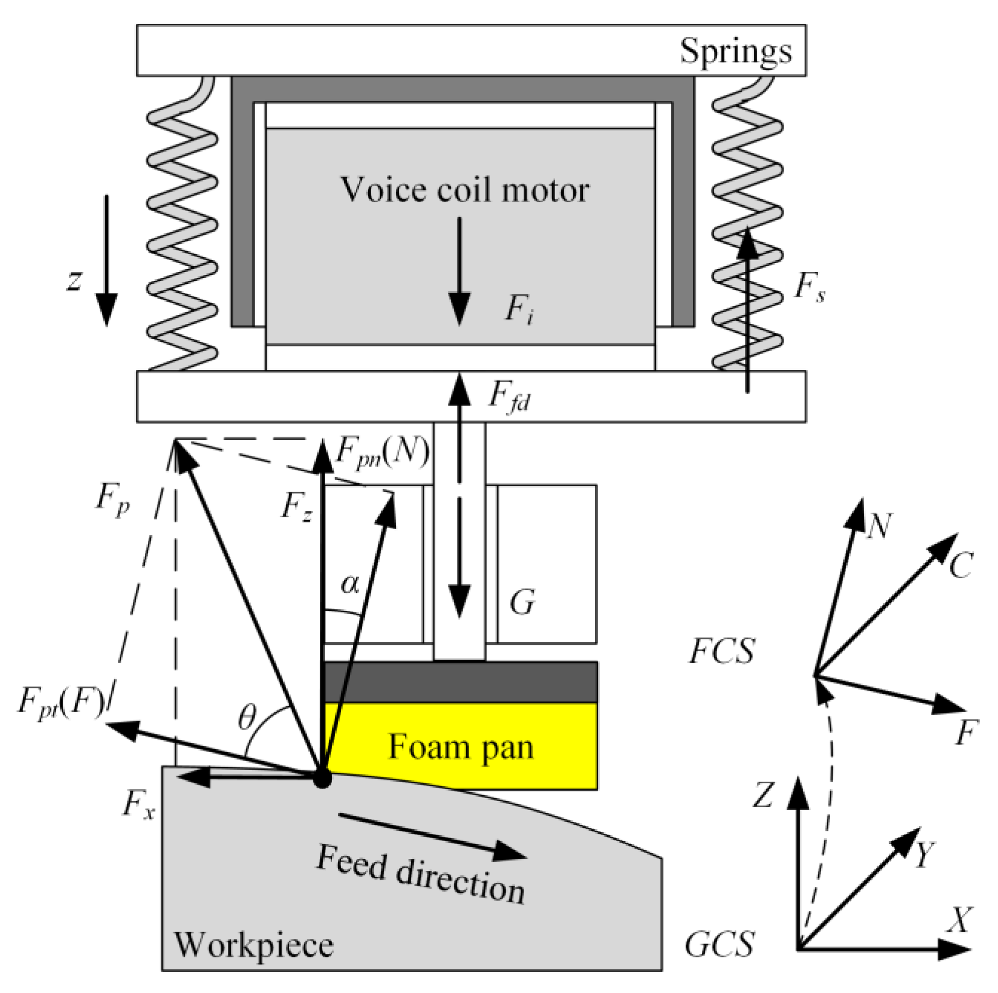
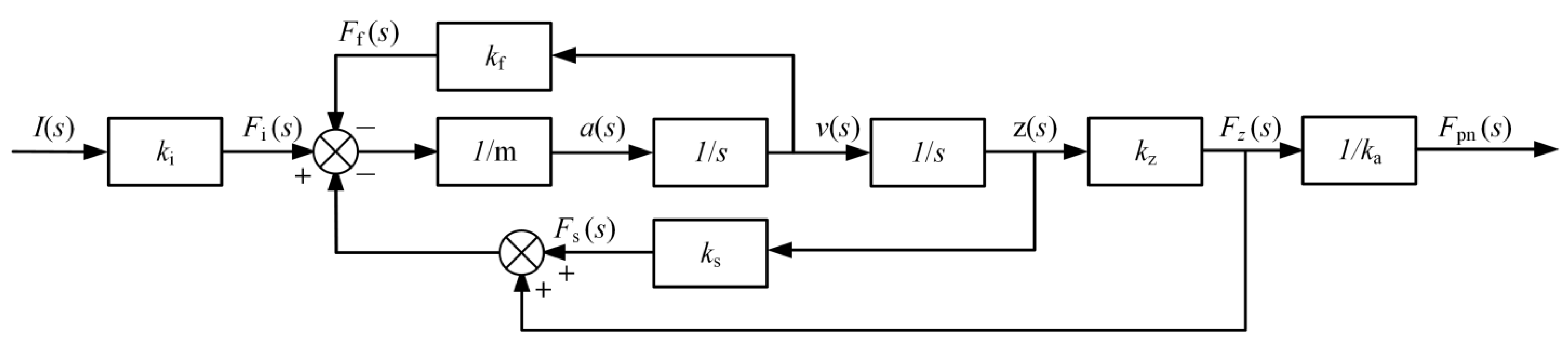
3.1. Polishing Force Analysis and Modeling of Device

To implement the force control of the device, it is first necessary to conduct mathematical modeling of the device to obtain the transfer function. In order to more clearly express the analysis process, the parameters of this section are listed in Table 2.
According to the following Preston polishing removal function, the removal rate of the polishing point is proportional to the pressure when the speed and feed speed of the force-controlled polishing device are constant. Therefore, controlling the constant normal force Fpn in the polishing process can ensure the uniformity of the polishing removal effect on the polishing path. The formula of Preston polishing removal function [37] is displayed as below:
d z / d t = K p P V
where dz/dt is the material removal in unit time, Kp is the Preston coefficient, which is related to the abrasive size and environment, P is the pressure at the polishing point, and V is the instantaneous polishing velocity at the polishing point.
Through the force analysis of the contact point shown in Figure 4, in the feed coordinate system (FCS), the polishing force Fp can be divided into normal force Fpn in the normal direction n and tangential polishing force Fpt in the tangential direction t.
F p = F pn + F pt
According to the theory of dynamic friction, the values of Fpn and Fpt can be obtained as
F pt = F pn tan ( π / 2 θ ) = F pn cot θ
where (π−θ) is the angle of friction and is only related to the material and roughness of the foam polishing pan and the PMMA part.
Next, the polishing force Fp can be expressed as follows:
F p = F pn 2 + F pt 2 = F pn 1 + co t 2 θ
In global coordinate system(GCS), the polishing force Fp can be equivalent to the force Fx in the X direction and the force Fz in the Z direction.
F p = F pn + F pt
According to the force analysis, when the contact angle is α, Fz can be obtained as follows:
F z = F p sin ( θ + α )
From Equations (4) and (6), Fz can be described as follows:
F z = F pn 1 + cot 2 θ sin ( θ + α ) = k a F pn
Through the above analysis, it can be concluded that when the contact angle α is constant, the Fz of the device is proportional to the polishing force Fp, which is defined as ka.
According to the force analysis of the device, when the voice coil motor is not enabled and the foam polishing pan is not in contact with the PMMA part, the device is in a static state when the axial displacement z = 0, and forces in the Z direction can be obtained as follows:
F i = 0 F z = 0 F f = 0 F s ( 0 ) = G
where Fi is the axial thrust generated by the voice coil motor, Fz is equal to the axial thrust received by the foam polishing pan, and Ff is the friction damping force.
When the voice coil motor is enabled, the foam polishing pan is in contact with the PMMA part, the axial displacement generated by the voice coil motor of the device is defined as z and the force equation of the device is as follows:
F i = m d 2 z d t 2 + F s + F f + F z G
The Lorentz force generated by the voice coil motor is proportional to the current of the current I passed through the coil, and this proportion is defined as the voice coil motor force coefficient ki. The frictional damping force is usually defined as proportional to the velocity of motion, which is defined as kf. The elastic coefficient of the springs is ks. The proportion of the elastic force of the foam pan to the displacement is defined as kz. The G is the gravity of the device. Consequently. each force can be expressed as follows:
F i = k i I F s = G + k s z F f = k f d z d t F z = k z z
By taking Equations (4) and (6) into consideration, the force equation of the device can be derived as follows:
k i I = m d 2 z d t 2 + k f d z d t + ( k s + k z ) z
From Equations (7), (10), and (11), the equation of current I to the contact force Fpn can be expressed as follows:
I = m k a k i k z d 2 F p n d t 2 + k f k a k i k z d F p n d t + k a ( k s + k z ) k i k z F p n
Take Laplace transforms of Equation (12) to yield the following:
I ( s ) F p n ( s ) = m k a k i k z s 2 + k f k a k i k z s + k a ( k s + k z ) k i k z
The transfer function of the device is shown below, and a block diagram of the transfer function is shown in Figure 5.
F p n ( s ) I ( s ) = k i k z m k a s 2 + k f m s + ( k s + k z ) m

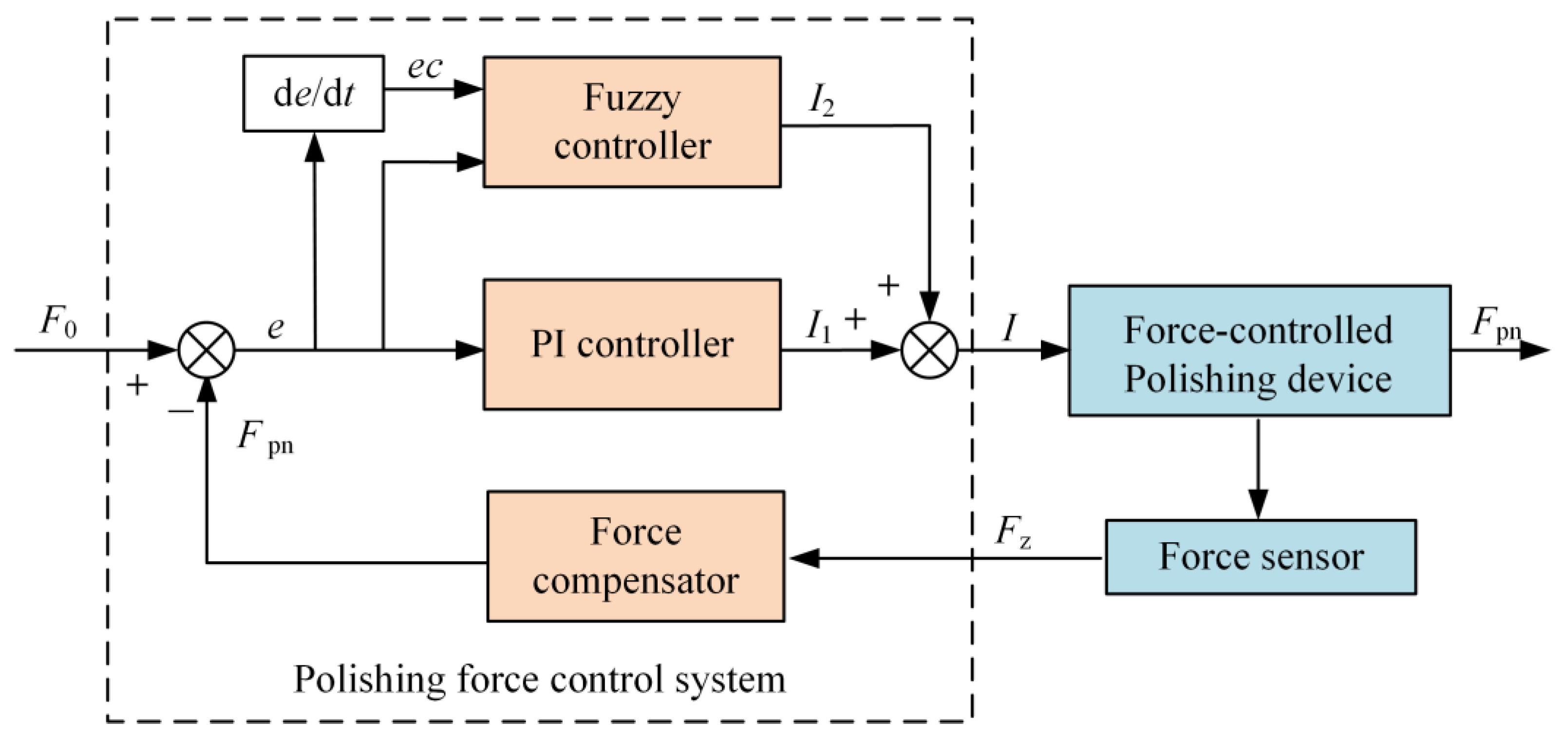
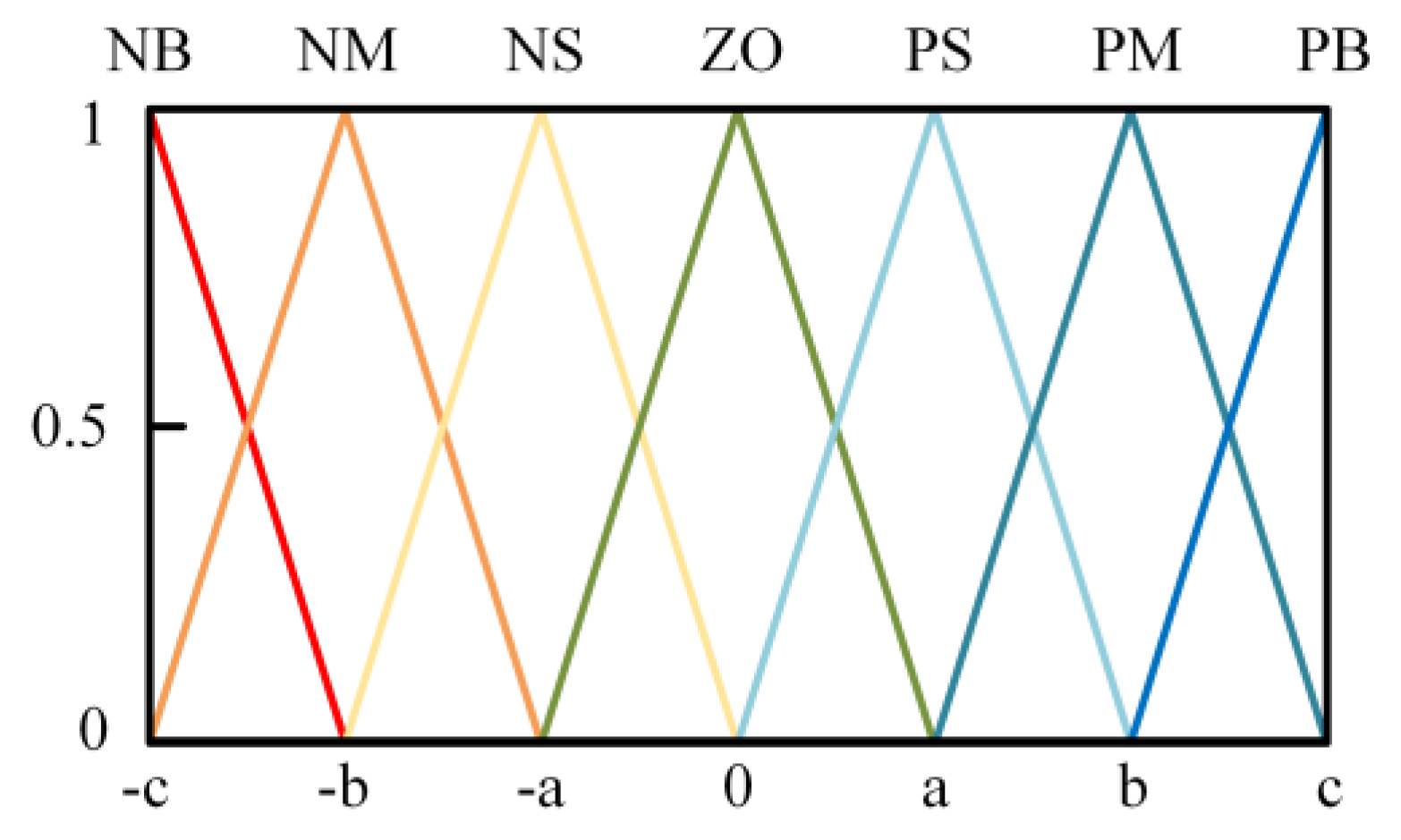
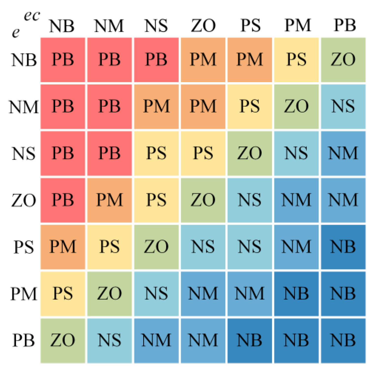
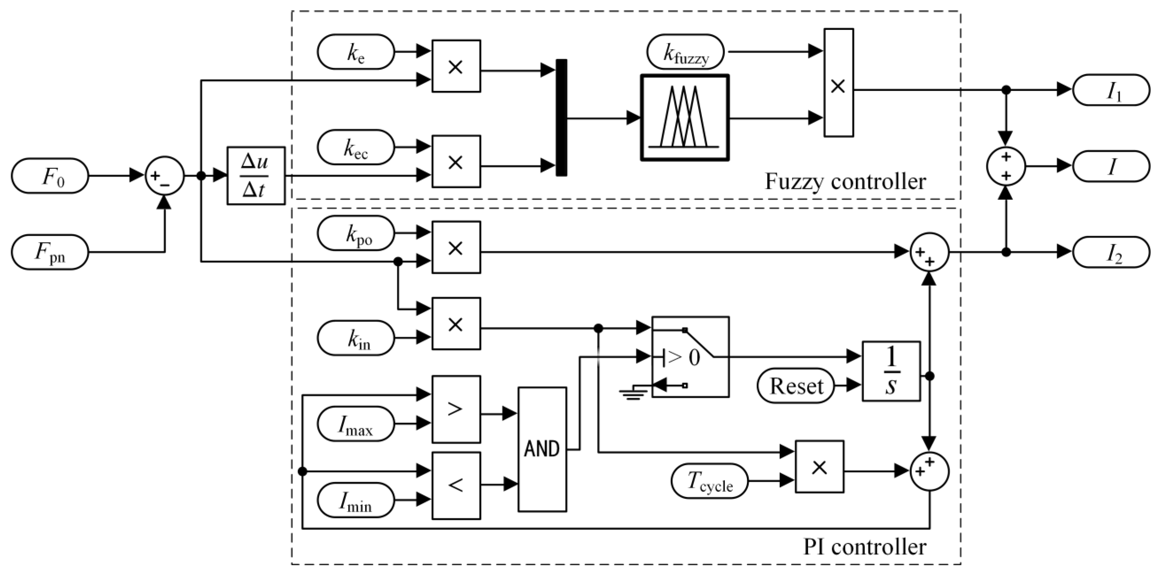
3.2. Force Control with Fuzzy PI Controller

A PI controller with the advantages of simple algorithm, strong robustness, and high reliability can be used to control the contact force accurately in the polishing process, and the control parameters can be adjusted by simulation. The output I1 of the PI controller can usually be expressed as follows:
I 1 = k p o e ( t ) + k i n 0 t e ( t ) d t
where kpo is the proportional coefficient, kin is the integral coefficient, and their values are preliminarily determined by the transfer function of the force-controlled polishing device established above.
The proportional control is used to quickly reduce the errors when the deviation is large, and the integral controller is adapted to eliminate static errors for ensuring control accuracy and improving the adaptability. Meanwhile, in order to prevent the integral controller from accumulating a large output value over time before the tool makes contact with the workpiece, the anti-saturation algorithm of the integral controller of is given as follows:
e i n = e ( t ) ,   I min < I in < I max 0 ,   I in I min I in I max
where ein is the input error of the integral controller, Iin is the output current of the integral controller, Imin is the minimum current of the device, and Imax is the maximum current of the device.
However, the impact during the approaching phase will bring some nonlinear and time-varying errors. These errors will bring greater polishing force between the polishing tool and the PMMA part, which will cause scratches and burns on the PMMA part. The fuzzy control algorithm is adopted. It is mainly used to solve some control problems in complex systems that have strong nonlinearity and time variability or cannot be described by accurate mathematical models.
The fuzzy PI controller is used as the strategy of the force control system, for which a block diagram is shown in Figure 6. In the diagram, F0 is the target force of the polishing. The error e is the difference between F0 and the contact force value Fpn, which is used as the input of the PI controller to calculate the value I1. Simultaneously, the value I2 is obtained from e and its rate of change over time ec from the fuzzy controller. Finally, the input current value of the polishing device I, consisting of I1 and I2, leads the device to produce the normal polishing force Fpn between the polishing tool and the PMMA part.
The input value e, ec and the output value I2 of the fuzzy system are described by seven fuzzy subsets, denoted as NB, NM, NS, ZO, PS, PM, and PB. The quantitative domain of e, ec is set to (−3, −2, −1, 0, 1, 2, 3), and the quantitative domain of I2 is set to (−1.5, −1, −0.5, 0, 0.5, 1, 1.5). Considering the sensitivity and coverage, each fuzzy subset uses a triangular membership function, which is shown in Figure 7.
An important step in the fuzzy controller is to establish fuzzy control rules [38]. The rule base of the fuzzy controller is established according to the experimental experience and shown in Figure 8. The redder color in the figure indicates that the positive output control of the variable should be increased, and the bluer color indicates that the negative output control of the corresponding variable should be increased, which corresponds to the fuzzy rule one by one.
The parameters are fuzzified by the fuzzy subset and fuzzy membership function defined above, and then the fuzzy system is established by MATLAB fuzzy logic toolbox. The fuzzy reason decision is made by the fuzzy control rules and the gravity center method is used to defuzzify. Therefore, there is the following:
I 0 = V x U I ( x ) d x V U I ( x ) d x
where, UI(x) is the output ambiguity, V is the output domain, and I0 is the result of the fuzzy set obtained by the center of gravity method. By multiplying I0 with the output quantization factor kfuzzy, the actual control value I2 is obtained as follows:
I 2 = k fuzzy I 0
Next, the final output I of the fuzzy PI controller can be expressed as follows:
I = I 1 + I 2
Finally, the current I, as the input signal of the device, results in the desired normal polishing force Fpn.

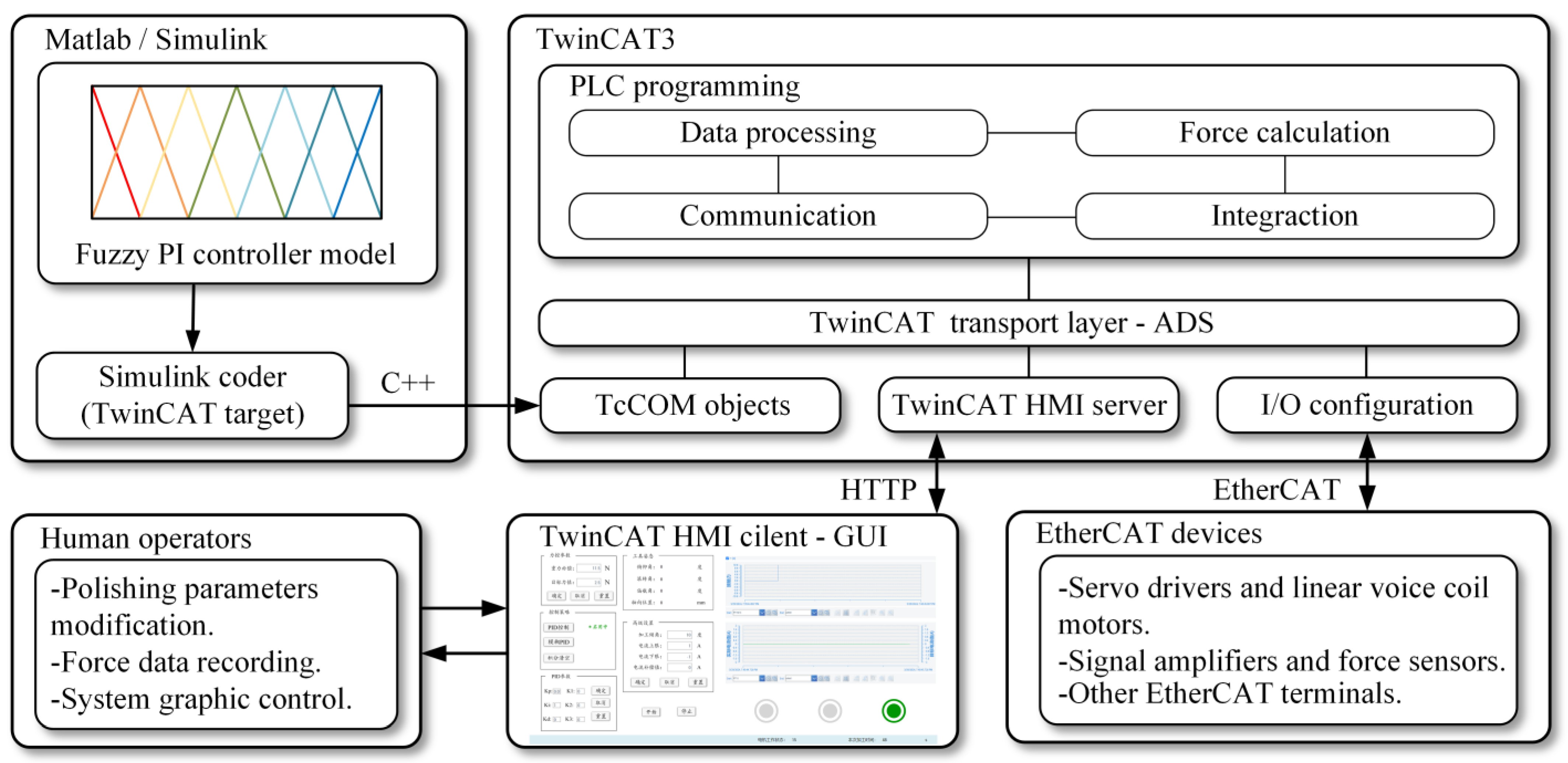
3.3. Implementation of Control Method

To implement the fuzzy PI controller, a fuzzy PI control model was developed on Simulink, as shown in Figure 9. The TwinCAT 3 software was adopted as the foundation of the force control system to configure programs and control the hardware, as illustrated in Figure 10. To apply the established Simulink control model to the control system, the Simulink coder converts the Simulink model into a C++ program. Subsequently, the target computer downloads the program as a TwinCAT component object model (TcCOM) object. This conversion enables researchers to focus more on control engineering issues rather than on programming skills [39]. Next, TcCOM objects communicate with programmable logic controller (PLC) components through the automation device specification (ADS) protocol, which is used between various components of TwinCAT. The PLC programming component serves as the primary component for communication, data processing, force calculation, and interaction. The communication function enables seamless information exchange between components, ensuring accurate and efficient data transmission. The data processing function involves the interpretation and manipulation of incoming data from sensors and other inputs. Central to the operation of the force control system, the force calculation function performs precise calculations for the normal polishing force. By calculating the normal polishing force based on input parameters and feedback from force sensors, the system can dynamically adjust the current of the voice coil motor to maintain the polishing force, ensuring stable polishing performance. The interaction function involves the ability to interact with operators through the TwinCAT human–machine interface (HMI) server. For human–computer interaction, the HMI server facilitates monitoring and control by human operators via a graphical user interface (GUI). The GUI allows operators to input parameters, adjust settings, and receive alerts and status reports. Meanwhile, the I/O component communicates with devices through the EtherCAT protocol to establish the connection between the software and the hardware. Consequently, the fuzzy PI controller model implements communication with the hardware of the device in the TwinCAT3 real-time running environment. In general, the software of the control system achieves the control model implementation, data processing and operation, communication with the hardware, and human–computer interaction. Additionally, TwinCAT 3 provides advanced real-time scheduling algorithms, ensuring accurate coordination between various components. This coordination is essential for achieving effective real-time closed-loop control of the polishing force.

4. Experiment and Verification

4.1. Experiment Settings

To assess the efficacy of the force-controlled polishing device, this study presents a polishing experiment conducted on a complex curved PMMA part using a five-axis CNC machining center equipped with the force-controlled polishing device. A PMMA part that was double-side milled by the machining center was used in the experiment. Its size was 300 mm × 215 mm × 50 mm and the radius of the curvature varied from 110 mm to 250 mm. Figure 11 shows the polishing process of the PMMA part. Figure 12 depicts the surface of the milled part, which exhibited an obvious scallop height of 10 μm, resulting in poor transparency. The roughness measurement result of the surface was Sa 926 nm.
Considering the balance between the surface quality and the processing efficiency, the polishing contact force was set at 5 N and the rotating speed of the spindle was set at 1000 r/min. As the cooling medium for polishing, water was used to help prevent burns from polishing and to avoid mutual solubility with the PMMA. To ensure the surface quality and optical properties of the PMMA parts, the polishing process needs a series of processes. Table 3 shows the polishing process schedule of the experiment. First, rough abrasive pieces of sandpaper measuring 60 μm, 30 μm, 15 μm, and 9 μm were used to remove the cusps generated in the milling process. Next, pieces of sandpaper measuring 2.7 μm and 1.25 μm were used twice each for semi-precision polishing. Finally, 3 M of each of the polishing liquids 81235 and 82877 was used with wool pads to finish the polish. According to the material removal distribution model, the line spacing of the polishing path was set at 10 mm, the polishing path between different processes was set at 5 mm, and the feed speed was set at 600 mm/min. Table 4 lists the polishing parameters of the polishing experiment.
In the polishing process, a comparative polishing experiment was conducted without force control for comparison. To verify the force control performance, the normal polishing force was measured by the force sensors integrated in the proposed device. Conversely, when the machining center performed the comparative polishing experiment, the linear voice coil motor of the device was turned off and the linear bearing was locked. To reduce the damage to the part, 2.7 sandpaper was used in the comparison experiment. To ensure a fair comparison, the machining center performed the same curved path motion, and the feed rate of 600 mm/min and the spindle speed of 1000 r/min were used in the experiment.

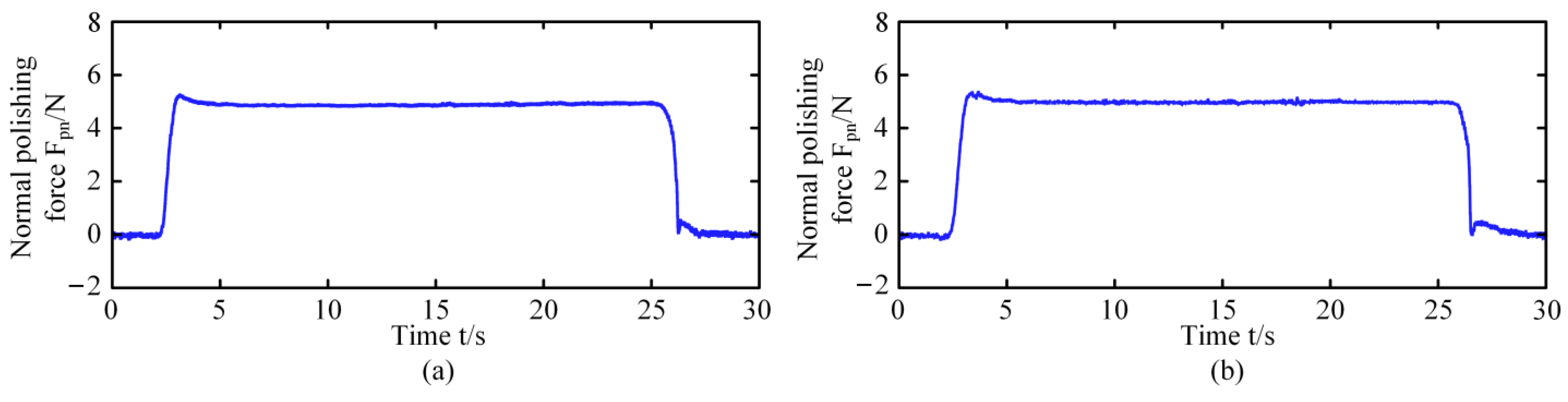
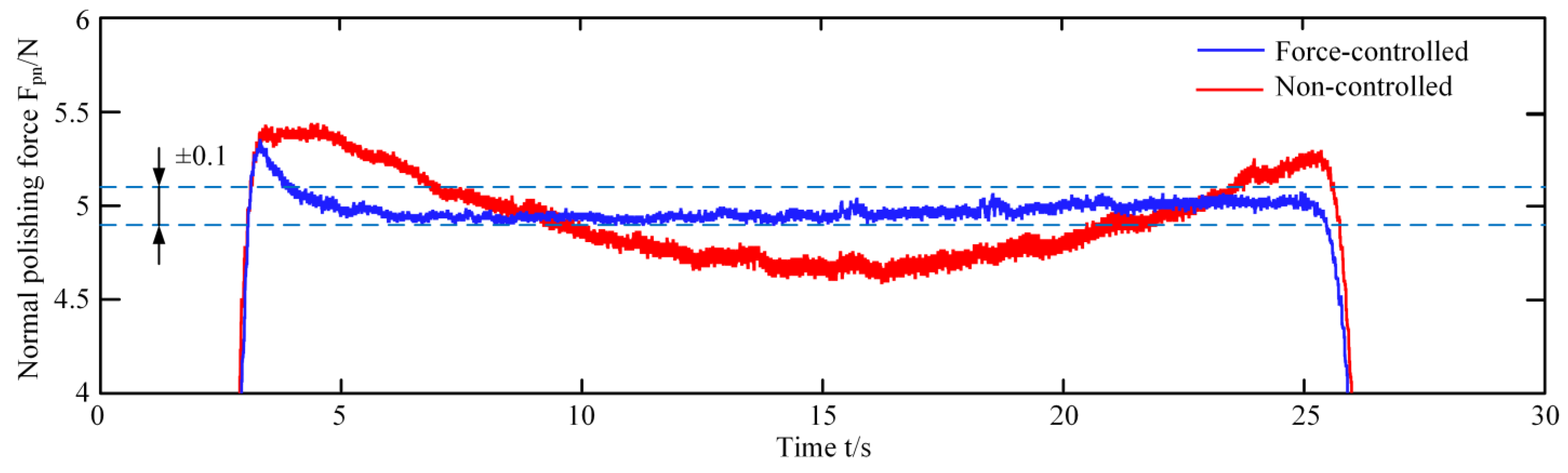
4.2. Results and Verification

Figure 13 shows the variation of the normal polishing force over time for two random trajectories on both convex and concave surfaces. It can clearly be seen that the polishing force is stably controlled during the polishing process and exhibits a small overshoot in the approaching phase. The controlled normal polishing force is maintained at the desired value during the polishing process, and the stable force is not affected by the surface curvature.
Figure 14 shows the comparison of the normal polishing force over time during the force-controlled polishing process and the non-controlled polishing process. The diagram clearly shows that the force-controlled polishing device enhances the stability of the polishing force, which is maintained in a stable range of 5 ± 0.1 N. During the approaching phase, the polishing force is controlled to exhibit a smaller overshoot of less than 0.5 N, and the response time is also significantly reduced.
To verify the surface quality of the workpiece, the roughness of the PMMA part was measured by the New View 9000 3D surface profiler from ZYGO Corporation, United States of America. The filter for the roughness measurement was a Gaussian spline filter with an 80-micrometer period of high pass. The measurement results were taken from four randomly distributed areas on the PMMA part, as shown in Figure 15. The figure reveals that the polished surface exhibits good consistency, and the roughness of each area is less than Sa 0.01 μm, significantly lower than the roughness of the milled surface. Next, the two-sided polished PMMA part was placed on a paper printed with “DUT”. The optical performance of the complex curved PMMA part is shown in Figure 16. It can be seen that the “DUT”, which was under the polished part, was clearly visible without deformation. Compared with the milled surface, the polished surface has a higher light transmittance. The results demonstrate that the force-controlled polishing device has a positive effect during the polishing of PMMA parts, resulting in better surface quality and optical performance.

5. Conclusions

In this paper, a force-controlled polishing system was presented for the polishing of complex curved PMMA parts on a machining center. The force-controlled polishing device with the linear voice coil motor and force sensors was used to perform the real-time active control of the polishing force. The compact structure, coupling the linear motion with the rotation of the spindle, reduced the inertia of the mechanical structure to enhance the response frequency. Next, the force-controlled polishing system with real-time hardware architecture ensured the low servo cycle of the control system. The polishing force between the device and the workpiece was analyzed and the mathematical model of the device was obtained. Through the polishing force analysis, a fuzzy PI controller was proposed to alleviate the impact during the approaching phase of the polishing and to reduce the overshoot value and response time. The controller model was established on Simulink and the control system was developed based on TwinCAT 3 software with real-time computing capability. Finally, a polishing experiment involving a complex curved PMMA part was conducted by the force-controlled polishing device integrated into a five-axis machining center. The experimental results show that the proposed device can maintain the normal polishing force within a range of 5 ± 0.1 N during the polishing process. Meanwhile, the surface roughness of the polished PMMA part with the complex curved surface was less than Sa 0.01 μm, with good surface quality and optical performance. The limitation of this research is that the linkage between the removal and the force control algorithm was not considered, meaning that only coincident material removal from the surface can be ensured, and that the profile errors of the workpiece cannot be corrected after polishing. In summary, the force-controlled polishing system proposed in this paper is positive and effective for the polishing of complex curved PMMA parts. However, the material removal method with a force-controlled polishing system still needs to be improved in the further research.

Author Contributions

Conceptualization, Y.S.; methodology, X.M. and Y.S.; software, X.M. and Y.W.; validation, X.M. and H.F.; formal analysis, X.M. and Y.W.; investigation, X.M., Y.W. and Y.S.; resources, Y.S.; data curation, X.M. and H.F.; writing—original draft preparation, X.M.; writing—review and editing, Y.W., X.Y., S.S. and Y.S.; visualization, X.M.; supervision, Y.S.; project administration, Y.S. All authors have read and agreed to the published version of the manuscript.

Funding

This research received no external funding.

Data Availability Statement

Data are contained within the article.

Conflicts of Interest

The authors declare no conflicts of interest.

References

  1. Wang, X.K.; Wei, S.C.; Xu, B.S.; Chen, Y.; Yan, X.; Xia, H.H. Transparent Organic Materials of Aircraft Cockpit Canopies: Research Status and Development Trends. Mater. Res. Innov. 2015, 19, S10-199–S10-206. [Google Scholar] [CrossRef]
  2. Guo, Q.; Wang, W.; Jiang, Y.; Sun, Y. 3D Surface Topography Prediction in the Five-Axis Milling of Plexiglas and Metal Using Cutters with Non-Uniform Helix and Pitch Angles Combining Runout. J. Mater. Process. Technol. 2023, 314, 117885. [Google Scholar] [CrossRef]
  3. Yan, S.; Sun, Y. Enhancing Tool Dynamics and Stability in Internal Turning with an Adjustable Clamping Device under Variable Cutting Conditions. Mech. Syst. Signal Process. 2024, 208, 111007. [Google Scholar] [CrossRef]
  4. Guo, Q.; Yang, Z.; Xu, J.; Jiang, Y.; Wang, W.; Liu, Z.; Zhao, W.; Sun, Y. Progress, Challenges and Trends on Vision Sensing Technologies in Automatic/Intelligent Robotic Welding: State-of-the-Art Review. Robot. Comput.-Integr. Manuf. 2024, 89, 102767. [Google Scholar] [CrossRef]
  5. Li, B.; Li, G.; Lin, W.; Xu, P. Design and Constant Force Control of a Parallel Polishing Machine. In Proceedings of the 2014 4th IEEE International Conference on Information Science and Technology, Shenzhen, China, 26–28 April 2014; IEEE: Piscataway, NJ, USA, 2014; pp. 324–328. [Google Scholar]
  6. Fan, C.; Xu, K.; Zhang, L.; Yuan, Q.; Wang, Q.; Wang, K.; Sun, L. Kinematic Planning and In-Situ Measurement of Seven-Axis Five-Linkage Grinding and Polishing Machine Tool for Complex Curved Surface. Mach. Sci. Technol. 2022, 26, 203–228. [Google Scholar] [CrossRef]
  7. Wang, G.M.; Zhan, J.M. Modeling of Machining Force Error in Aspheric Surface Polishing by Hybrid Movement/Force Control Policy. AMM 2011, 101–102, 795–799. [Google Scholar] [CrossRef]
  8. Ji, S.M.; Zhang, L.; Yuan, Q.L.; Jin, M.S.; Yuan, J.L. A Novel Ballonet Polishing Tool and Its Robot Control System for Polishing the Curved Surface of Mould. IJCAT 2007, 29, 212. [Google Scholar] [CrossRef]
  9. Wahjudi, A.; Shiou, F.J. Simulation Study of Sliding Control for Constant Polishing Force Using an Innovative Sphere-Like Polishing Tool on a Machining Center. AMR 2010, 126–128, 505–510. [Google Scholar] [CrossRef]
  10. Yong, J.; Peng, X.; Hu, H.; Zhao, T. Research on Key Technologies in the Conformal Polishing of Complex Surface Optical Components. In Proceedings of the AOPC 2019: Space Optics, Telescopes, and Instrumentation, Beijing, China, 7–9 July 2019; Xue, S., Zhang, X., Zhang, Z., Nardell, C.A., Eds.; SPIE: Beijing, China, 2019; p. 74. [Google Scholar]
  11. Zhang, L.; Ding, C.; Fan, C.; Wang, Q.; Wang, K. Process Planning of the Automatic Polishing of the Curved Surface Using a Five-Axis Machine Tool. Int. J. Adv. Manuf. Technol. 2022, 120, 7205–7218. [Google Scholar] [CrossRef]
  12. Sun, Y.; Feng, D.; Guo, D. An Adaptive Uniform Toolpath Generation Method for the Automatic Polishing of Complex Surfaces with Adjustable Density. Int. J. Adv. Manuf. Technol. 2015, 80, 1673–1683. [Google Scholar] [CrossRef]
  13. Xu, C.-Y.; Li, J.-R.; Liang, Y.-J.; Wang, Q.-H.; Zhou, X.-F. Trochoidal Toolpath for the Pad-Polishing of Freeform Surfaces with Global Control of Material Removal Distribution. J. Manuf. Syst. 2019, 51, 1–16. [Google Scholar] [CrossRef]
  14. Zeng, S.; Blunt, L. An Experimental Study on the Correlation of Polishing Force and Material Removal for Bonnet Polishing of Cobalt Chrome Alloy. Int. J. Adv. Manuf. Technol. 2014, 73, 185–193. [Google Scholar] [CrossRef]
  15. Chen, H.; Chen, C.-Y.; Li, J.; Fang, Z.; Li, H.; Li, G. Research on Polishing Parameters Optimization for Free Curved Surface. In Proceedings of the 2018 13th IEEE Conference on Industrial Electronics and Applications (ICIEA), Wuhan, China, 31 May–2 June 2018; IEEE: Piscataway, NJ, USA, 2018; pp. 2339–2344. [Google Scholar]
  16. Deng, Y.; Wang, G.; Yue, X.; Zhou, K. A Review of Robot Grinding and Polishing Force Control Mode. In Proceedings of the 2022 IEEE International Conference on Mechatronics and Automation (ICMA), Guilin, China, 7–10 August 2022; IEEE: Piscataway, NJ, USA, 2022; pp. 1413–1418. [Google Scholar]
  17. Dai, J.; Chen, C.-Y.; Zhu, R.; Yang, G.; Wang, C.; Bai, S. Suppress Vibration on Robotic Polishing with Impedance Matching. Actuators 2021, 10, 59. [Google Scholar] [CrossRef]
  18. Shiou, F.-J.; Banh, Q.-N. Development of an Innovative Small Ball-Burnishing Tool Embedded with a Load Cell. Int. J. Adv. Manuf. Technol. 2016, 87, 31–41. [Google Scholar] [CrossRef]
  19. Kakinuma, Y.; Igarashi, K.; Katsura, S.; Aoyama, T. Development of 5-Axis Polishing Machine Capable of Simultaneous Trajectory, Posture, and Force Control. CIRP Ann. 2013, 62, 379–382. [Google Scholar] [CrossRef]
  20. Oba, Y.; Yamada, Y.; Kakinuma, Y. Simultaneous Control of Tool Posture and Polishing Force on Unknown Curved Surface for Serial-Parallel Mechanism Polishing Machine. In Proceedings of the IECON 2015 41st Annual Conference of the IEEE Industrial Electronics Society, Yokohama, Japan, 9–12 November 2015; IEEE: Piscataway, NJ, USA, 2015; pp. 005351–005356. [Google Scholar]
  21. Asaga, R.; Yamato, S.; Kakinuma, Y. Analysis of Tool Posture Control Method on Curved Surface Using Polishing Machine with 5-Axis Serial-Parallel Mechanism. In Proceedings of the IECON 2017 3rd Annual Conference of the IEEE Industrial Electronics Society, Beijing, China, 29 October–1 November 2017; IEEE: Piscataway, NJ, USA, 2017; pp. 2979–2984. [Google Scholar]
  22. Sencer, B.; Kakinuma, Y.; Yamada, Y. Linear Interpolation of Machining Tool-Paths with Robust Vibration Avoidance and Contouring Error Control. Precis. Eng. 2020, 66, 269–281. [Google Scholar] [CrossRef]
  23. Tian, F.; Lv, C.; Li, Z.; Liu, G. Modeling and Control of Robotic Automatic Polishing for Curved Surfaces. CIRP J. Manuf. Sci. Technol. 2016, 14, 55–64. [Google Scholar] [CrossRef]
  24. Tian, F.; Li, Z.; Lv, C.; Liu, G. Polishing Pressure Investigations of Robot Automatic Polishing on Curved Surfaces. Int. J. Adv. Manuf. Technol. 2016, 87, 639–646. [Google Scholar] [CrossRef]
  25. Wang, D.; Li, J.; Guan, Y.; Chen, H.; Wang, B.; Zhang, T.; Liu, X.; Hong, J.; Zhang, H. A High-Bandwidth End-Effector With Active Force Control for Robotic Polishing. IEEE Access 2020, 8, 169122–169135. [Google Scholar] [CrossRef]
  26. El Khalick Mohammad, A.; Hong, J.; Wang, D. Design of a Force-Controlled End-Effector with Low-Inertia Effect for Robotic Polishing Using Macro-Mini Robot Approach. Robot. Comput.-Integr. Manuf. 2018, 49, 54–65. [Google Scholar] [CrossRef]
  27. Ma, Z.; Poo, A.-N.; Ang, M.H.; Hong, G.-S.; See, H.-H. Design and Control of an End-Effector for Industrial Finishing Applications. Robot. Comput.-Integr. Manuf. 2018, 53, 240–253. [Google Scholar] [CrossRef]
  28. Chen, F.; Zhao, H.; Li, D.; Chen, L.; Tan, C.; Ding, H. Contact Force Control and Vibration Suppression in Robotic Polishing with a Smart End Effector. Robot. Comput.-Integr. Manuf. 2019, 57, 391–403. [Google Scholar] [CrossRef]
  29. Yu, Y.; Wang, R.; Wang, Y.; Sun, Y. Contact Force Controlled Robotic Polishing for Complex PMMA Parts with an Active End-Effector. J. Adv. Manuf. Sci. Technol. 2021, 1, 2021012-0. [Google Scholar] [CrossRef]
  30. Zhang, X.; Sun, Y. Development of Pneumatic Force-Controlled Actuator for Automatic Robot Polishing Complex Curved PMMA Parts. Machines 2023, 11, 446. [Google Scholar] [CrossRef]
  31. Grochała, D.; Dudzińska, S.; Bachtiak-Radka, E.; Gubała, R. Micro-Hydraulic Burnishing Tools for Integrated Machining on CNC Milling Center. AIP Conf. Proc. 2018, 2029, 020018. [Google Scholar] [CrossRef]
  32. Bachtiak-Radka, E.; Dudzińska, S.; Grochała, D.; Berczyński, S.; Olszak, W. The Influence of CNC Milling and Ball Burnishing on Shaping Complex 3D Surfaces. Surf. Topogr. Metrol. Prop. 2017, 5, 015001. [Google Scholar] [CrossRef]
  33. Mitropoulos, T.; Avrampos, P.; Vosniakos, G.C. Development of a Polishing Jig for Machining Centres. SSP 2017, 261, 167–172. [Google Scholar] [CrossRef]
  34. Ahn, J.; Park, S.; Sim, J.; Park, J. Dual-Channel EtherCAT Control System for 33-DOF Humanoid Robot TOCABI. IEEE Access 2023, 11, 44278–44286. [Google Scholar] [CrossRef]
  35. Chuang, W.-L.; Yeh, M.-H.; Yeh, Y.-L. Develop Real-Time Robot Control Architecture Using Robot Operating System and EtherCAT. Actuators 2021, 10, 141. [Google Scholar] [CrossRef]
  36. Wang, S.; Yang, X.; Geer, J.V.D. Development of EtherCAT Real-Time Control System for Robot Based on Simulink Real-Time. JCM 2021, 21, 49–57. [Google Scholar] [CrossRef]
  37. Li, J.; Li, L.; Zhou, B.; Zhao, J.; Zhu, G.; Wang, Z. A Robotic Multi-directional Polishing Trajectory Generation Method Based on Preston-PSO Algorithm. China Mech. Eng. 2023, 34, 1729–1740. [Google Scholar]
  38. Eghbal Ahmadi, M.H.; Royaee, S.J.; Tayyebi, S.; Bozorgmehry Boozarjomehry, R. A New Insight into Implementing Mamdani Fuzzy Inference System for Dynamic Process Modeling: Application on Flash Separator Fuzzy Dynamic Modeling. Eng. Appl. Artif. Intell. 2020, 90, 103485. [Google Scholar] [CrossRef]
  39. Dang, Q.V.; Allouche, B.; Dequidt, A.; Vermeiren, L.; Dubreucq, V. Real-Time Control of a Force Feedback Haptic Interface via EtherCAT Fieldbus. In Proceedings of the 2015 IEEE International Conference on Industrial Technology (ICIT), Seville, Spain, 17–19 March 2015; IEEE: Piscataway, NJ, USA; pp. 441–446. [Google Scholar]
Figure 1. The mechanical structure of force-controlled polishing device.
Machines 12 00259 g001
Figure 2. Hardware architecture diagram of control system.
Machines 12 00259 g002
Figure 3. Force-controlled polishing system diagram.
Machines 12 00259 g003
Figure 4. Device force analysis diagram.
Machines 12 00259 g004
Figure 5. Device transfer-function block diagram.
Machines 12 00259 g005
Figure 6. Block diagram of fuzzy PI controller.
Machines 12 00259 g006
Figure 7. Triangular membership function diagram.
Machines 12 00259 g007
Figure 8. Fuzzy control rules diagram.
Machines 12 00259 g008
Figure 9. Simulink-model block diagram of fuzzy PI controller.
Machines 12 00259 g009
Figure 10. Block diagram of software.
Machines 12 00259 g010
Figure 11. Polishing process of the PMMA part.
Machines 12 00259 g011
Figure 12. Milled surface. (a) Blurred surface with 10 μm of scallop height. (b) Surface roughness measurement result.
Machines 12 00259 g012
Figure 13. Normal polishing force over time in the polishing process of complex curved PMMA part. (a) Polishing force of convex surface. (b) Polishing force of concave surface.
Machines 12 00259 g013
Figure 14. Comparison of the normal polishing force of convex surface between force-controlled and non-controlled polishing processes.
Machines 12 00259 g014
Figure 15. Surface roughness measurement results of four random areas of the complex curved PMMA part.
Machines 12 00259 g015
Figure 16. Optical performance of polished complex curved PMMA part.
Machines 12 00259 g016
Table 1. Parameters of the force-controlled polishing device.
ParametersValues
Total mass4.0 kg
Movable mass1.6 kg
Total length290 mm
Motion stroke10 mm
Polishing tool size 76 mm
Sampling frequency1 kHz
Resolution of force sensor0.01 N
Force control range0–30 N
Table 2. Parameters of polishing force analysis.
ParametersParameters
Kpm2/NPreston coefficientka coefficient of the force in the Z direction and normal polishing force
PN/m2pressure at the polishing pointzmaxial displacement
Vm/sinstantaneous polishing velocity at the polishing pointFiNaxial thrust generated by the voice coil motor
dz/dtm/smaterial removal in unit timeFfNfriction damping force
FpNpolishing forceIAcurrent passed through the coil
FpnNnormal polishing forcekiN/Avoice coil motor force coefficient
FptNtangential polishing forcekfN·s/mfrictional damping force coefficient
θdegreescomplementary angle of friction angleksN/melastic coefficient of the springs
FxNforce in the X directionkzN/melastic coefficient of the foam pan
FzNforce in the Z directionGNgravity of the moving part of the device
αdegreescontact anglemkgmass of the moving part of the device
Table 3. Polishing process schedule.
ProcessAbrasive Size (μm)CycleFeed Rate (mm/min)Spindle Speed (r/min)
16016001000
230
315
49
52.72
61.252
7Polishing liquid3500
Table 4. Parameters of polishing process.
ParametersValues
Path interval10 mm
Contact angle α10°
Sensor sample time1 ms
Controller cycle time1 ms
Controller coefficient kp, ki, kfuzzy1, 0.05, 0.015
Disclaimer/Publisher’s Note: The statements, opinions and data contained in all publications are solely those of the individual author(s) and contributor(s) and not of MDPI and/or the editor(s). MDPI and/or the editor(s) disclaim responsibility for any injury to people or property resulting from any ideas, methods, instructions or products referred to in the content.

