1. Introduction
Surface texturing refers to the use of specific processing techniques to produce microstructures with certain sizes, shapes, and permutations on the surface of friction pairs, which can be used to improve the hydro-dynamic lubrication performance of mechanical components [
1]. Under fluid lubrication conditions, the cavitation effect [
2,
3] caused by a reasonably designed surface texture can significantly increase the bearing capacity [
4] of the friction pairs. The theoretical and experimental research on the cavitation effect of the texture are key methods for studying the lubrication characteristics of such friction pairs [
5,
6,
7,
8].
The experimental research equipment for the cavitation effect caused by the surface texture of friction pairs generally uses a visual friction testing machine [
9]. A large number of experimental studies have confirmed that the micro-texture on the surface of friction pairs not only enhances the load-bearing capacity between interfaces through the hydrodynamic lubrication effect of micro-regions but also enhances the lubrication capacity through induced cavitation. Due to the hydrodynamic lubrication effect in the micro-region, the pressure of the lubricating oil decreases in the divergent region at the entrance of the texture. At the outlet of the texture, the pressure of the lubricating oil increases. These two can usually compensate for each other, and thus the net bearing capacity between the interfaces is rather small. However, a sharp decrease in pressure at the entrance of the texture can lead to cavitation [
10,
11,
12]. Due to cavitation, the trend of pressure reduction in the low-pressure area is suppressed, increasing the total bearing capacity and the tendency for the oil film to become thicker (i.e., the bearing capacity between interfaces is improved) [
13].
Regarding the source of cavitation bubbles, an earlier view believed that cavitation was caused by the evaporation of lubricant due to low pressure, but Reiner Wahl et al. [
10] believed that the trapping of air in the lubricant during friction is the main cause of cavitation. Liu [
14] observed the phenomenon of micro-texture-induced cavitation using a high-speed camera and found that the area of cavitation bubbles increases with the extension of the experimental time and gradually reaches a stable state. Wang et al. [
15] also found that the low-pressure region of asymmetric micro-texture-induced cavitation can capture dissolved gases or carried bubbles from the lubricating oil, which explains the phenomenon where the actual cavitation pressure is much greater than the evaporation pressure of the lubricating oil. For the shape of bubbles, Sun et al. [
16,
17] pointed out that because bubbles usually generate faster in the low-pressure region and dissolve more slowly in the high-pressure region where the texture converges, the cavitation zone can grow and may overflow from the texture region, forming a comet tail-shaped cavitation zone downstream.
At present, many experimental studies on the influencing factors of micro-texture-induced cavitation, such as the shape, size, and distribution of textures, as well as the velocity, load, and lubricant viscosity, found a significant impact on cavitation phenomena and lubrication characteristics [
18,
19,
20,
21]. Although more and more friction pairs are using highly elastic materials such as polymer composites, there is relatively little research on the surface texture-induced cavitation phenomenon in elastic materials. Su et al. [
22] revealed the elastic deformation of a relatively soft material surface texture under lubrication conditions and found that the texture shape will affect the elastic deformation inside the texture. It is necessary to avoid using a textural shape with a sharp-angled converging edge because its large elastic deformation affects the hydrodynamic effect.
The Reynolds number of the lubricating fluid between the friction pair interfaces with micro-textures is large, the oil film thickness changes rapidly, and the fluid flow field is complex. To obtain accurate results, a numerical simulation model based on the Navier–Stokes equation is generally used, and the numerical solution is usually obtained through CFD simulation [
23,
24]. With the improvement in computer performance and the wide application of the N-S equation, it has become an inevitable trend to use the N-S equation to solve the lubrication model with a micro-textured surface under the condition of considering the cavitation effect. Xi Shi et al. [
25] established a two-dimensional CFD model. In the simulation results, there was an optimal value for texture parameters such as the film thickness ratio and film width ratio of the micro-groove structure, achieving the maximum load capacity and minimum friction coefficient. The cavitation pressure also had a significant effect on the load capacity. Gao et al. [
26] established a non-uniform multi-scale model, focusing on the influence of micro-cavitation generated by a small-scale morphology, and used a mass conservation small-scale model to simulate cavitation on bearings. Jiang et al. [
27] studied the effect of different texture arrays on lubrication performance in a three-dimensional CFD model. The results show that when the texture inclination angle was 26.6°, the friction coefficient was 29.4% lower than that of the smooth surface.
In summary, although research on the cavitation effect caused by the surface texture of friction pairs in elastic matrix materials is quite important, there is currently a lack of comprehensive and in-depth research on the influence and mechanism of the texture-induced cavitation effect on the lubrication characteristics of elastic materials through CFD numerical simulations combined with visual experiments; There is relatively little research on the influencing factors (such as the distribution of the texture on the bearing) of the cavitation effect caused by the surface texture of elastic sliding bearing friction pairs. Based on this, this article proposes investigating how elastic deformation affects the cavitation effect and lubrication performances of textured elastic matrix materials. The two-dimensional numerical simulations of the elastic surface texture were carried out by ANSYS Fluent software Fluent 16.0. The effects of the texture location, the elastic modulus of the bearing material, and the shaft speed on the lubrication performance of the bearing friction pairs were studied. To verify the correctness of the simulation results, the generation of cavitation was observed by a visual sliding bearing test bench.
2. Materials and Methods
To investigate the cavitation effect and lubrication characteristics of elastic surfaces induced by a micro-texture, a two-dimensional numerical model in the fluid domain was established based on the N-S equation. To simplify the simulation, the following assumptions were made: the lubricating medium was incompressible Newtonian fluid and was not affected by the volume force; the fluid flow was steady; the velocity of the wall fluid was the same as that of the wall motion; and the basic assumptions of other N-S equations were implemented.
Based on the above assumptions, the expansion of the N-S equation in the x and y directions is
The continuous equation is
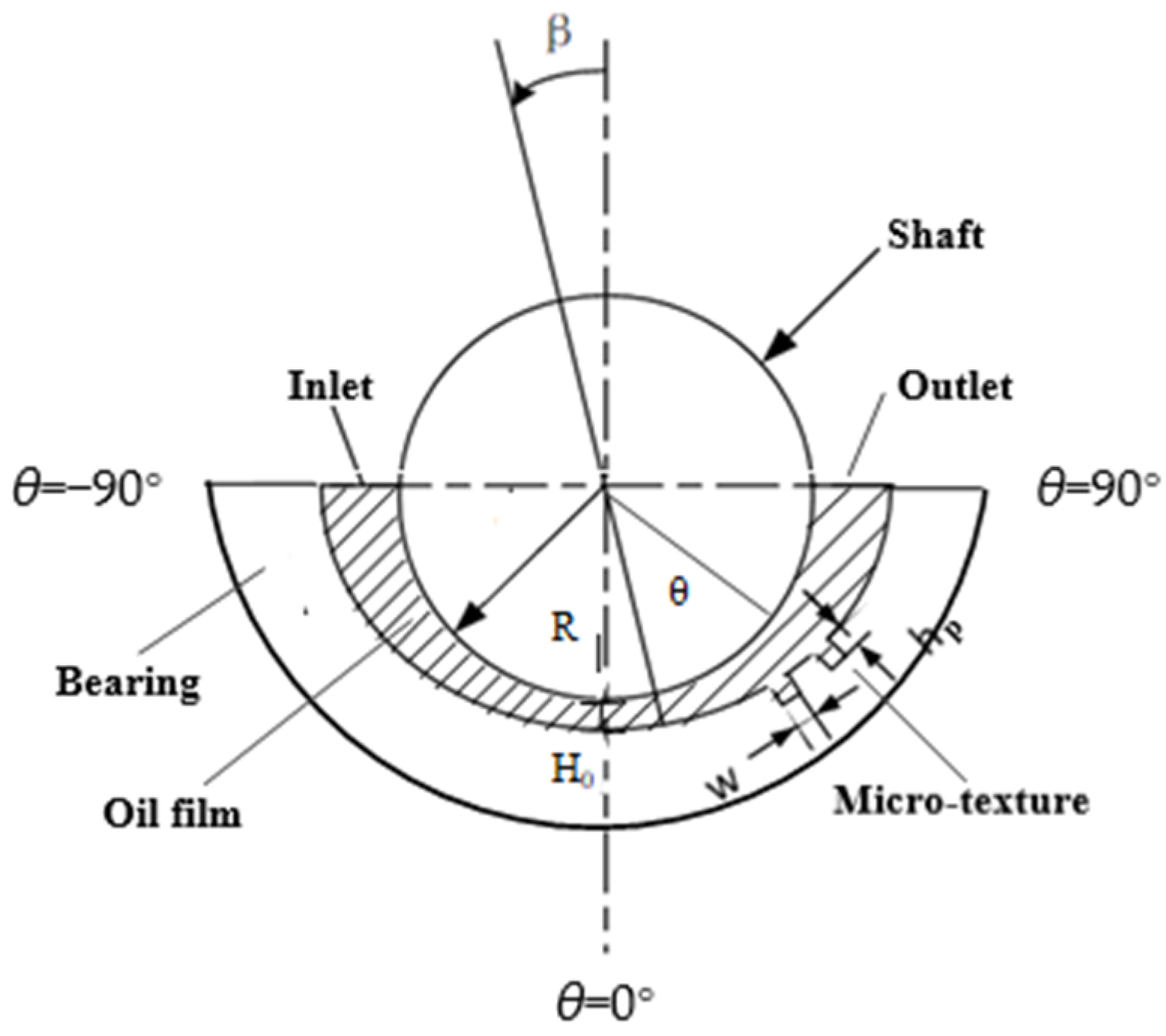
The geometric model of the elastic plain bearing friction pair is shown in
Figure 1. Here,
θ is the circumferential angle (°),
β is the offset angle (°),
R is the shaft radius (mm),
w is the texture width (mm),
h is the texture depth (mm), and
Hf is the minimum oil film thickness (mm). In this experiment, the loading force was applied in the direction of
θ = 90°, this loading force acted on the minimum oil film position, and the offset angle
β in the simulation was 0. The minimum oil film thickness
Hf in the simulation was 0.01 mm. The physical parameters used in the simulation are shown in
Table 1.
To ensure accuracy, the following dimensionless parameters were used in the simulation:
The fluid force acting on the surface of the upper wall could be decomposed into the tangential friction
Fτ and normal bearing capacity
Fη, where the equations for
Fτ and
Fη are
The use of friction coefficient can more conveniently evaluate the lubrication performance of interfaces, and the friction coefficient
f between interfaces is obtained by the following formula:
The cavitation model is the Schnerr–Sauer model, and the phase transition rate is as follows:
In the formula, Re and Rc are the steam generation rate and steam condensation rate, respectively; RB is the cavity radius (m); ρm, ρv, and ρl are the densities of the mixed medium, vapor phase, and liquid phase (kg/m3), respectively; αv is the gas volume fraction; P and Pv are the flow field pressure and vaporization pressure (Pa), respectively; and n is the number of bubbles per unit liquid volume, which is generally 1013.
There was contact between two cylinders with radii of
R1 and
R2 with parallel axes. In the contact between two cylinders, the force is linearly proportional to the indentation depth. The half-width b of the rectangular contact area of two parallel cylinders is found as follows:
where
E1 and
E2 are the moduli of elasticity for cylinders 1 and 2, respectively,
ν1 and
ν2 are the respective Poisson’s ratios, and
L is the length of contact.
The maximum contact pressure along the center line of the rectangular contact area is
3. Results
The following part of the study adopts the numerical simulation model described in the previous section to investigate the relationship between the location of micro-textures on bearings, the elastic modulus of the bearing material, the shaft speed on the friction coefficient, and the bearing capacity between interfaces through numerical simulation. Through analysis and discussion, the mechanisms of the effect of the elastic material’s surface texture on cavitation and lubrication are obtained.
3.1. The Influence of the Texture on Different Locations in Calculation
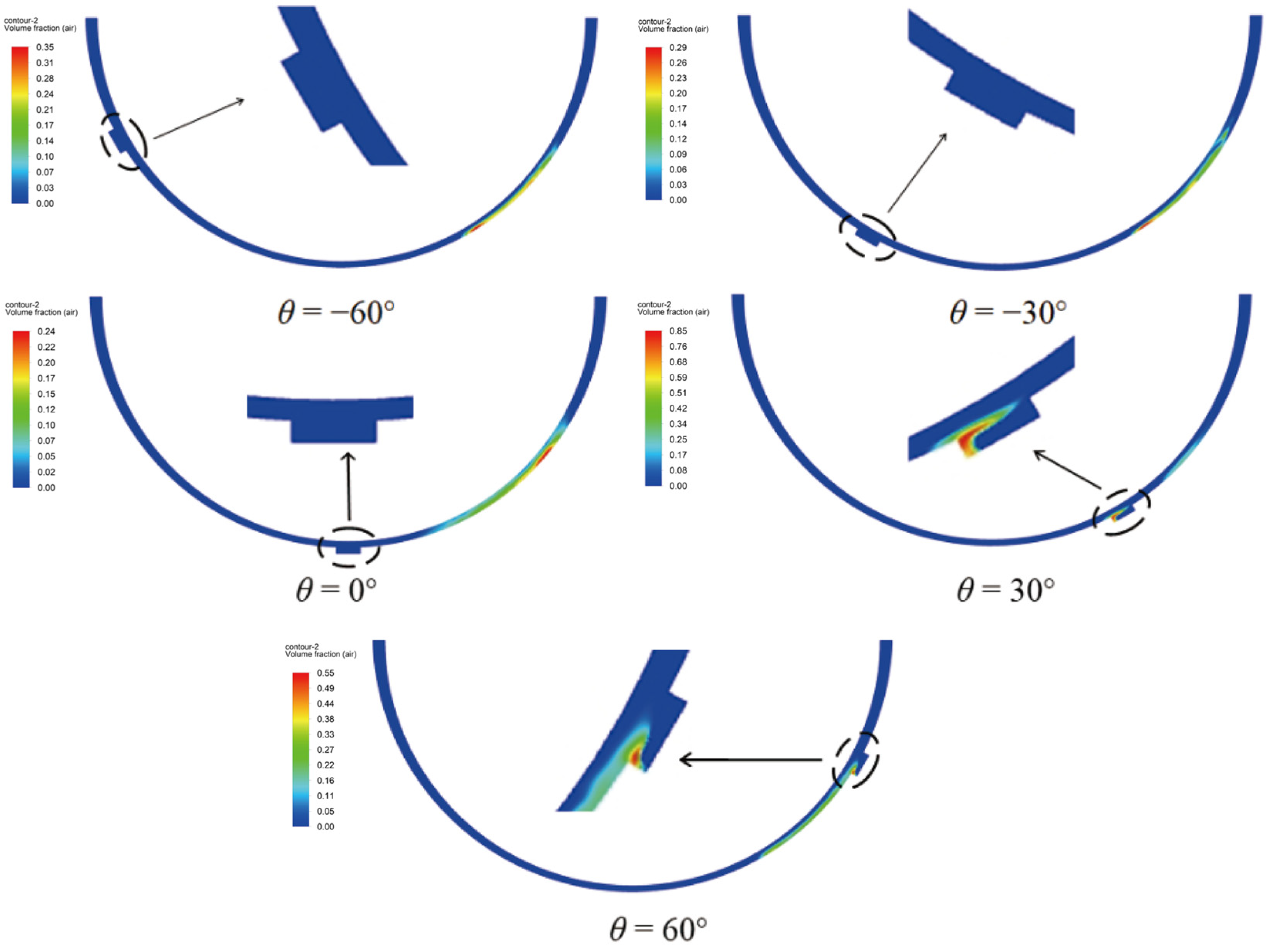
The selected distribution positions
θ of the elastic texture were −60°, −30°, 0°, 30°, and 60°. Through simulation, the ratio distributions of the gas generated by micro-zone cavitation corresponding to different micro-texture positions on the bearing were obtained, as shown in
Figure 2.
As shown in
Figure 2, when the micro-texture was arranged in the entrance area or the corresponding position of the minimum oil film, such as at −60°, 30°, and 0°, there was no local cavitation phenomenon inside the texture. When the texture was arranged at 30° and 60°, there was an obvious local cavitation phenomenon in the texture. In addition, the texture also had a significant impact on the macroscopic cavitation in the bearing outlet area. For example, when the texture distribution was at 0°, the macroscopic cavitation area was closer to the corresponding position of the minimum oil film.
The reason for the above phenomenon is that when the texture was arranged in the outlet area, the low pressure formed by the hydrodynamic lubrication effect of the bearing and the low pressure in the divergent area of the texture inlet were combined, forming a lower pressure inside the texture. When this pressure was lower than the cavitation pressure of the lubricating oil, local cavitation would occur inside the texture. In addition, due to the convergence of the micro-texture outlet, local high pressure was generated downstream, and the magnitude and position of this pressure would affect the position of the macroscopic cavitation area at the bearing outlet.
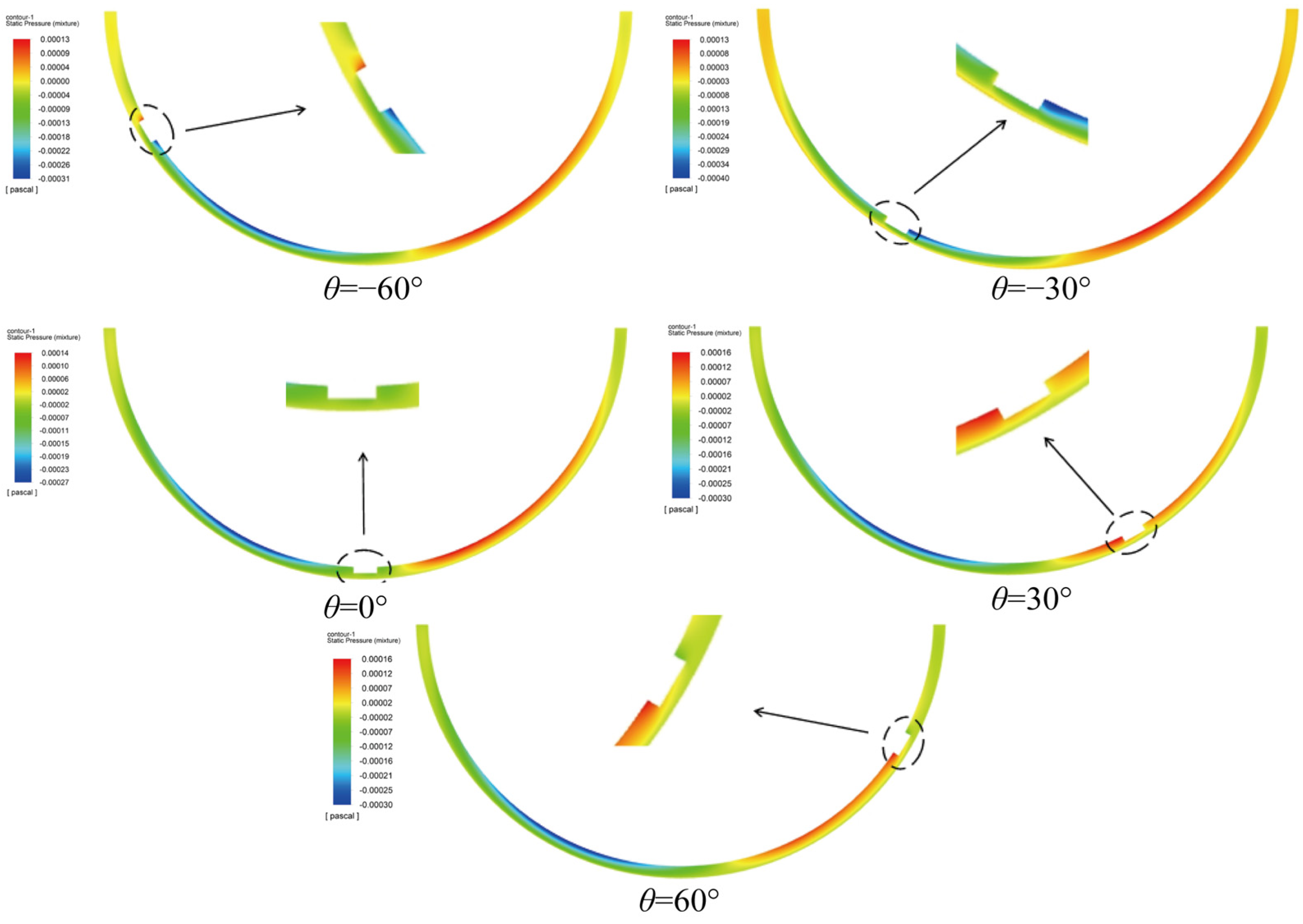
The elastic material located on the lower wall produced a small upward elastic deformation in the inlet area due to low pressure and was compressed in the outlet area due to high pressure, showing a more obvious downward elastic deformation. Therefore, the texture and its distribution position in the circumferential direction of the bearing affected the overall oil film pressure. The texture affected the change in the gap between the convergence zone and the divergence zone. When the texture was arranged at a position of −60°, the front end of the texture widened the wedge gap that originally converged, and the oil film pressure rose briefly and then decreased rapidly. The depression region was formed at the front end of the texture, and the solid domain was expanded upward by low pressure. At the back end of the texture, the solid domain was compressed downward by high pressure.
When the texture was arranged at the −30° position, it was similar to that at the −60° position. The depression region at the front end of the texture affected the increase in oil film pressure. However, due to the increase in oil film pressure in the flow, the oil film pressure decreased at the front end of the texture, but it was still higher than the initial pressure. The convergence zone where the texture was located showed a downward compression deformation trend. When the texture was arranged at 0°, the oil film pressure at the front end of the texture was similar to that at the back end of the texture, the texture made the high-pressure area of the originally connected convergence zone and the low-pressure area of the divergence zone smaller, and the elastic deformation of the bearing wall surface decreased. When the texture was arranged at 30° and 60°, the low-pressure area was concentrated near the front position of the texture, and the divergent area where the texture was located showed an upward expansion deformation trend. The deformation of the front end of the texture is more obvious in
Figure 3.
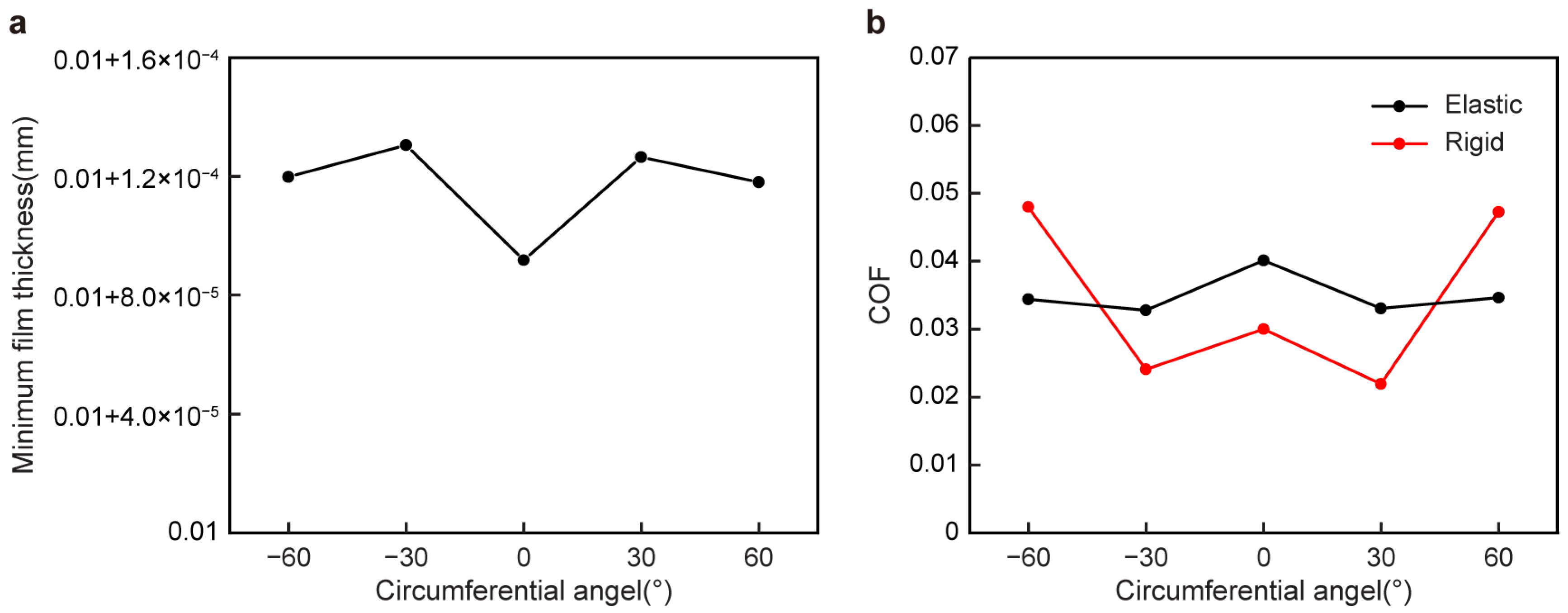
The changing trends of the elastic sliding bearing friction pair and the rigid sliding bearing friction pair were the same, as shown in
Figure 4. When the circumferential position
θ of the texture changed from −60°, −30°, 0°, or 30° to 60°, the oil film pressure also changed. The minimum oil film thickness increased first, then decreased, and then increased, and the friction coefficient decreased first, then increased, and then decreased. The difference is that the friction pair of the elastic sliding bearing had stronger stability due to the elastic deformation of the bearing wall. The friction coefficient changed more smoothly with the texture distribution angle. Near −60° and 60°, the friction coefficient of the elastic texture was lower than that of the rigid texture. However, at 30°, 0°, and −30°, the friction coefficient of the elastic texture was higher compared with the rigid bearing. Similarly, Li et al. [
28] pointed out that the loading capacity declines after considering the effect of elasticity.
3.2. Influence of Elastic Modulus in Calculation
To study the effect of the elastic modulus on the lubrication characteristics, the selected moduli of elasticity E were 5 MPa, 10 MPa, 15 MPa, 20 MPa, 25 MPa, and 30 Mpa.
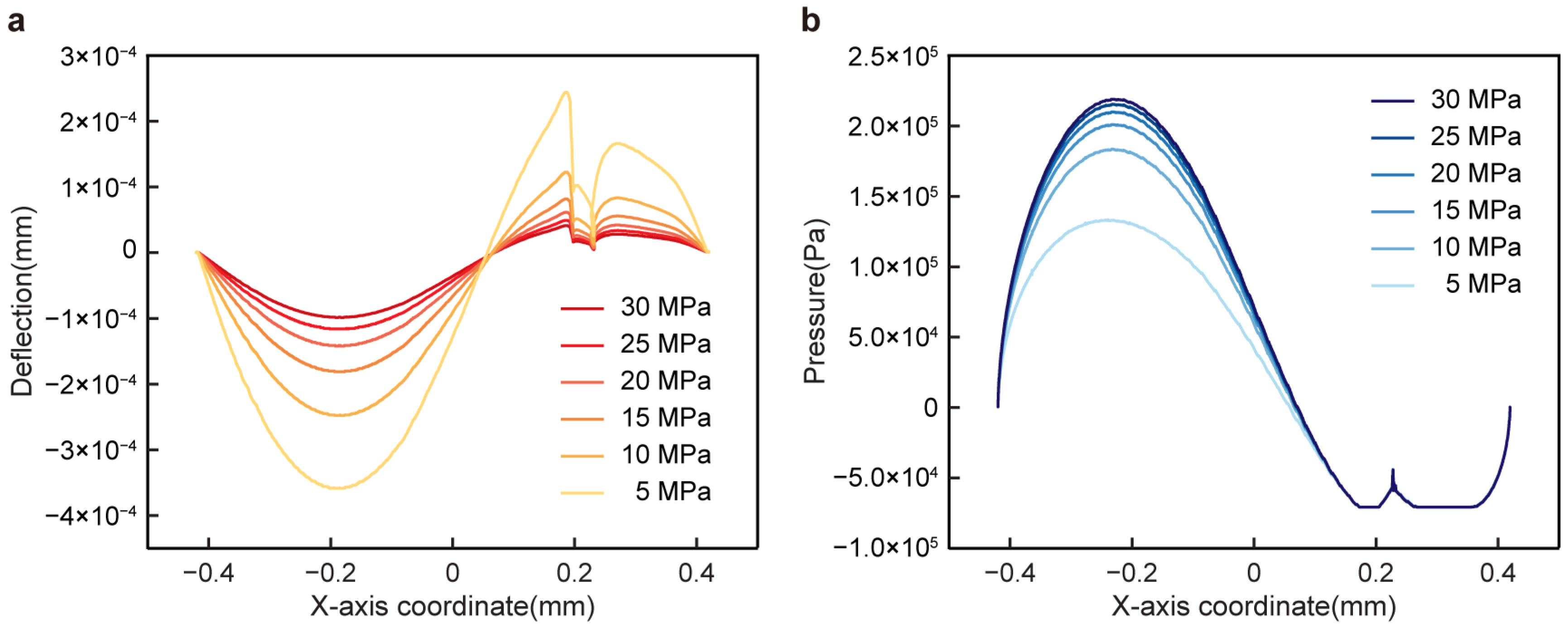
Figure 5 depicts the elastic material of the bearing wall producing a downward elastic deformation in the lubricating oil inlet area due to high pressure, and the elastic deformation became more obvious as the elastic modulus decreased. With the increase in the elastic modulus, the elastic deformation of the wall decreased obviously, and the oil film pressure increased. As shown in
Figure 5a, cavitation occurred when the oil film pressure in the divergence zone dropped to the cavitation pressure such that the lower oil film pressure in the divergence zone no longer continued to decline, which led to the deformation of the divergence zone wall subjected to low-pressure upward expansion being smaller than that of the convergence zone wall subjected to high-pressure downward compression. The cavitation zones with different elastic moduli were similar, ranging from 0.16 mm to 0.36 mm in the x direction of the model.
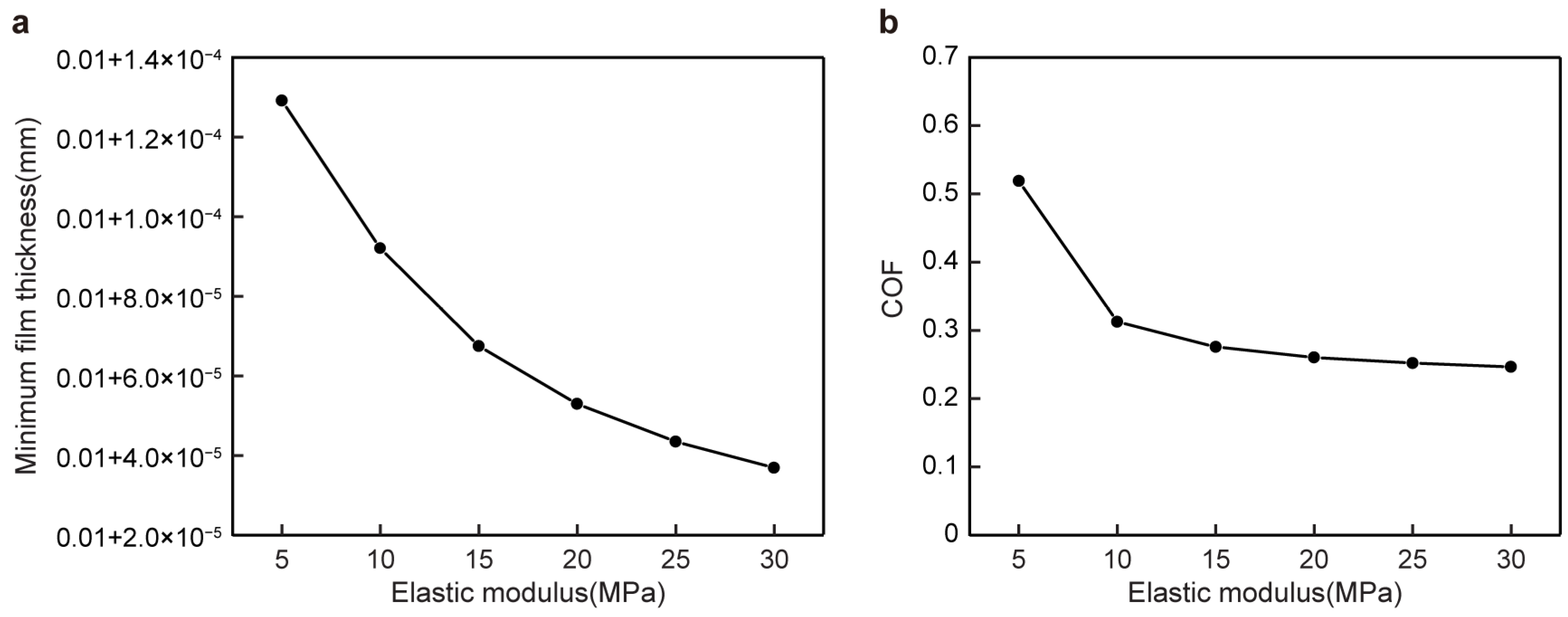
The friction coefficient and the minimum oil film thickness gradually decreased with the increase in the elastic modulus of the wall in
Figure 6, which improved the lubrication effect of the friction pair. As the elastic modulus of the wall decreased, the wall of the friction pair gradually became thinner, the minimum oil film thickness gradually increased, the oil film pressure distribution was gentler in the circumferential direction, and the friction coefficient increased slightly. Considering the elasticity, the minimum thickness of the oil film increased while the loading capacity decreased, and the friction coefficient increased. The friction coefficient also increased with the decrease in the elastic modulus [
29].
3.3. Influence of Bearing Speed in Calculation
To explore the influence of the elastic friction pair on the cavitation performance, the changing trend was obtained by changing the speed. The selected upper wall sliding speeds V were 2000 rpm (0.084 m/s), 2500 rpm (0.105 m/s), 3000 rpm (0.127 m/s), 3500 rpm (0.147 m/s), 4000 rpm (0.168 m/s), and 4500 rpm (0.188 m/s).
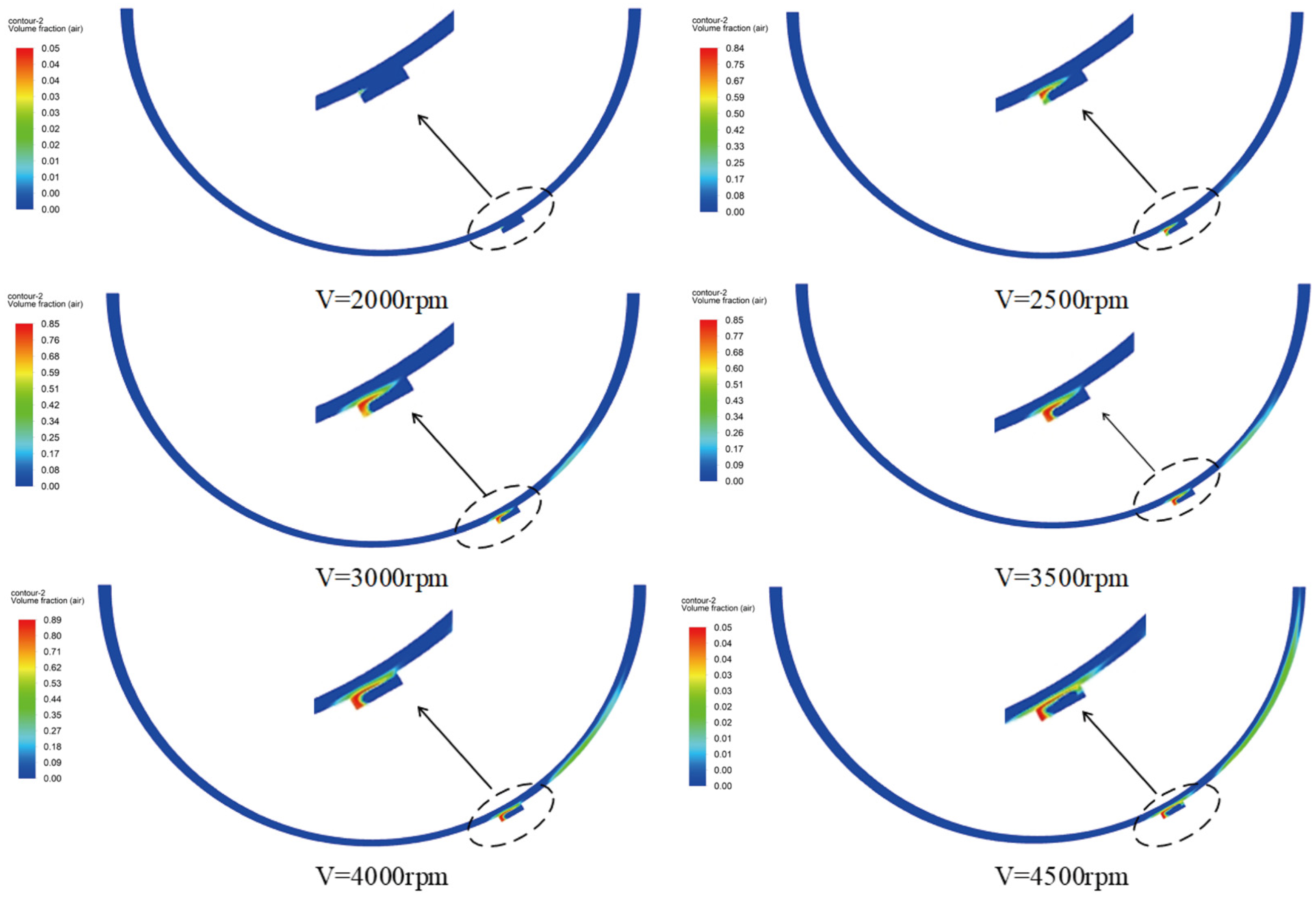
Figure 7 shows that as the rotation speed increased from 2000 rpm to 4500 rpm, the oil film pressure also changed, and the cavitation phenomenon inside the texture and in the area was more obvious. When the upper wall speed was 2000 rpm, there was no cavitation in the texture and the divergence area. When the rotation speed increased to 2500 rpm, cavitation occurred at the front end of the texture, and as the rotation speed increased, the cavitation area gradually developed to the outside of the texture. When the rotation speed increased to 4000 rpm and 4500 rpm, the cavitation area inside the texture would extend to the outside of the texture. In addition, with the increase in rotational speed, the two cavitation zones inside the texture and the divergence zone were close to each other.
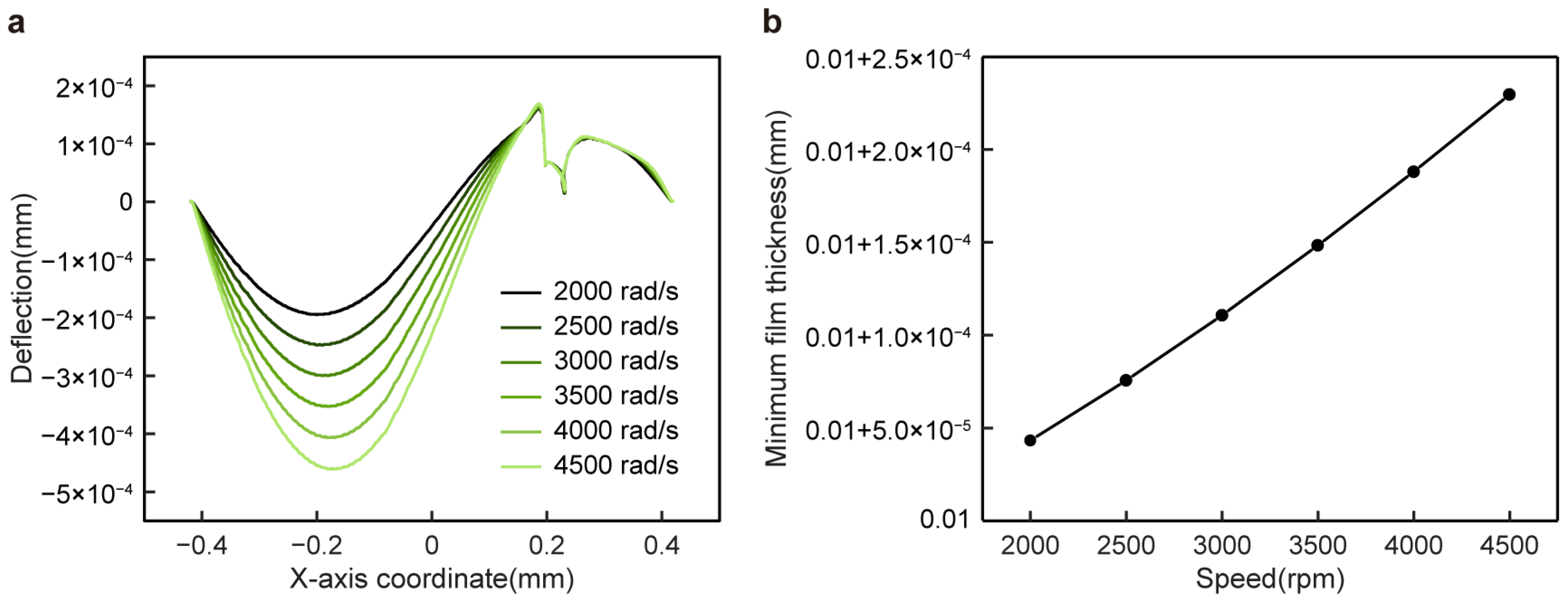
The oil film pressure increased with the increase in the rotational speed, which made the wall’s elastic deformation increase and the oil film thicken, meaning that the bearing capacity increased gradually, and the dynamic pressure lubrication effect is better in
Figure 8.
3.4. Experiment Apparatus and Preparation
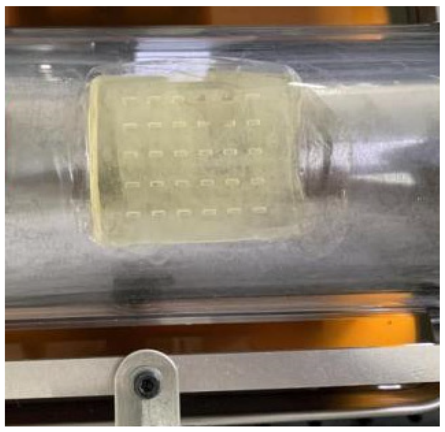
The elastic sample material was UV-curable resin. According to the parameters of
Table 2, for the friction pair of an elastic sliding bearing with a surface texture, a 3D printer was used to prepare an elastic film with a micro-texture as an elastic sample (
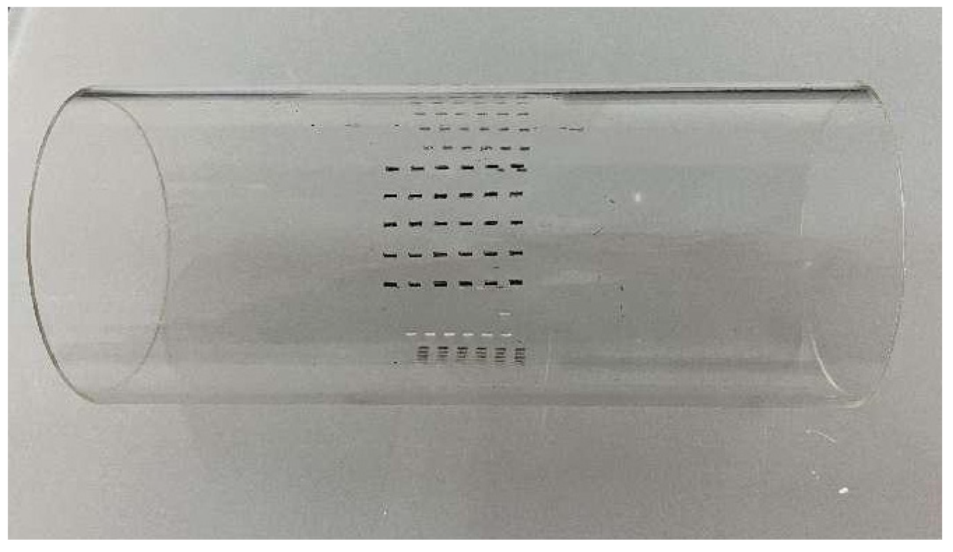
Figure 9). A coating of a mixture of graphite powder and gypsum powder was used as the auxiliary absorption layer, and the rigid sample was obtained by etching the back of the glass placed on the surface of the auxiliary absorption layer by the back dry etching method under laser irradiation (
Figure 10). The rigid sample material was glass.
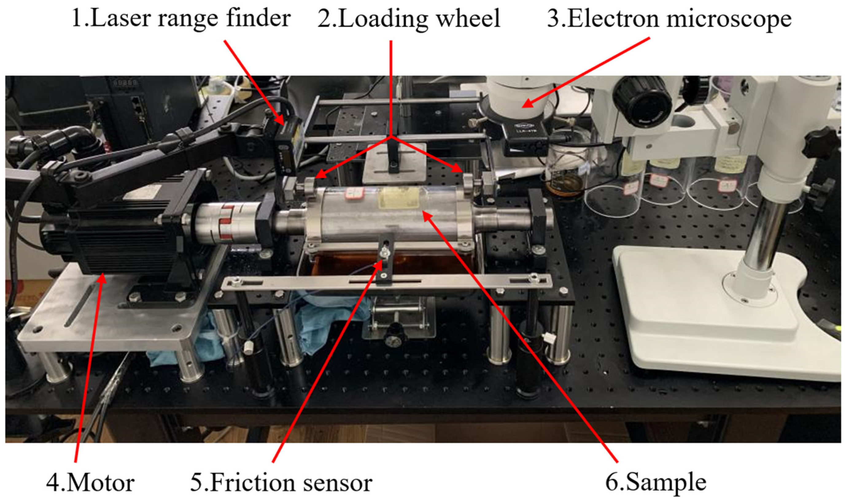
A microscopic imaging acquisition device was used to observe the cavitation phenomenon induced by the micro-texture during the lubrication process (
Figure 11). The cavitation gas phase diagram was transmitted and collected with a computer. The pressure sensor digital display showed the instantaneous pressure, and the instantaneous friction force of the friction pair was obtained by conversion. The change in lubricating oil film thickness during the experiment was collected by a laser displacement sensor, and its change trend was recorded.
3.5. Observation Results of Different Rotational Speeds on Elastic Material
According to the parameters in
Table 3, the friction pair of an elastic sliding bearing with a surface texture was studied and compared with the friction pair of a rigid sliding bearing with a surface texture. The bearing material was steel. The cavitation phenomenon induced by the surface texture of the elastic material was observed by changing the rotational speed, and its influence on the cavitation phenomenon and coefficient of friction was studied.
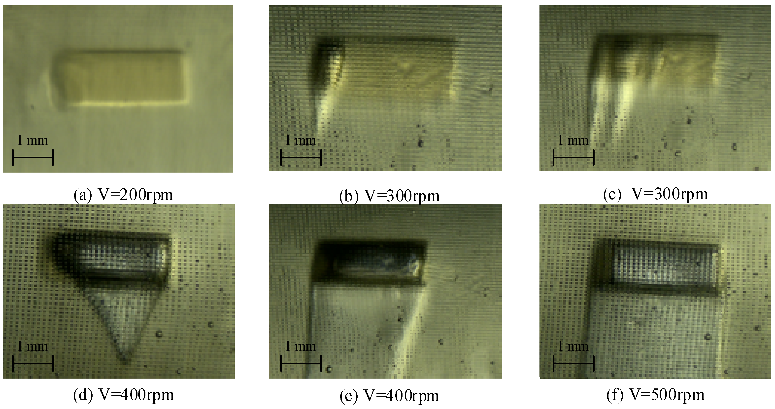
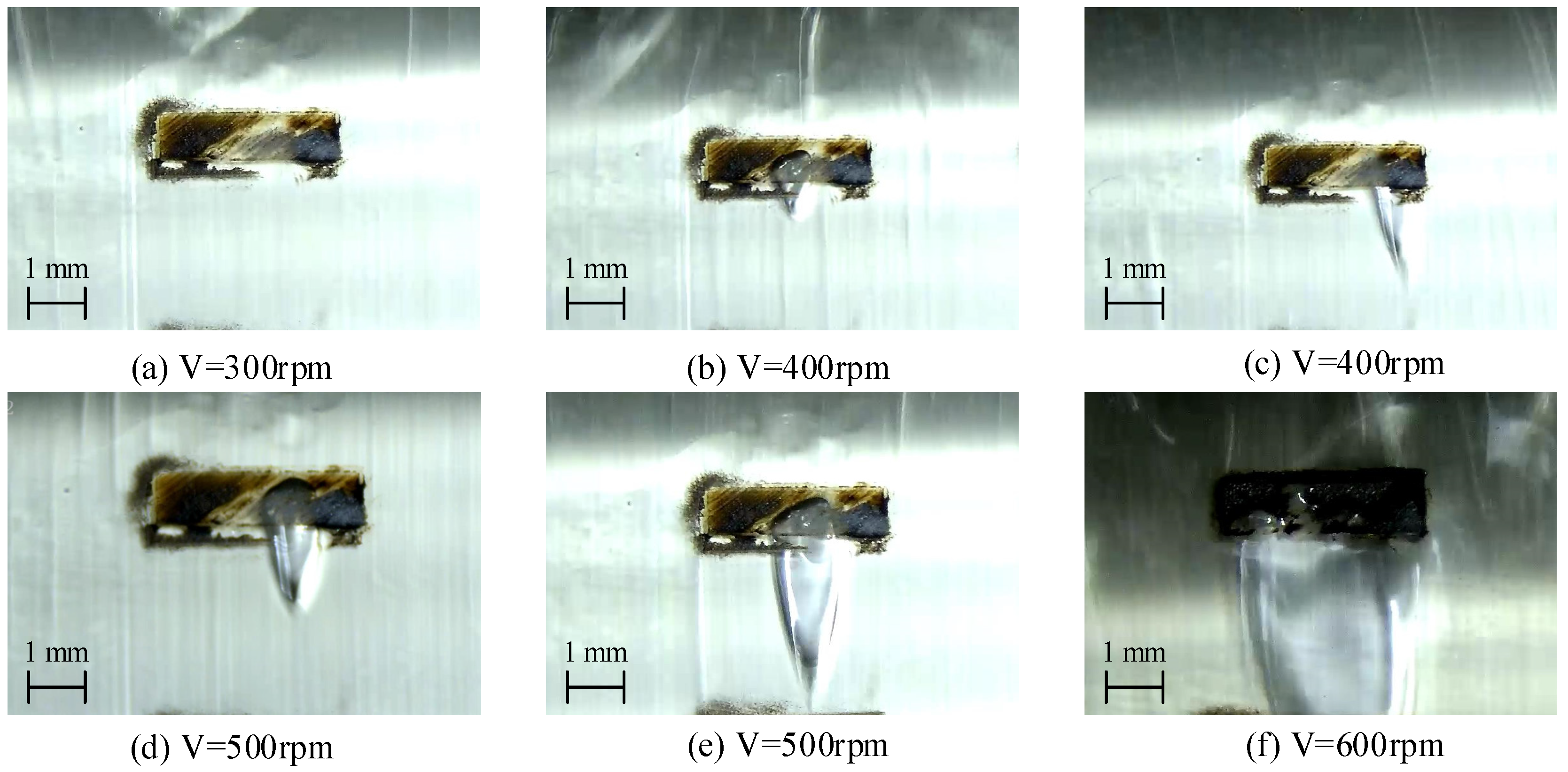
Figure 12 shows the cavitation phenomenon of the elastic surface texture. When the rotation speed was 100 rpm and 200 rpm, there was no cavitation in the texture (
Figure 12a). When the rotation speed of the shaft gradually increased to 300 rpm, cavitation occurred in the texture (
Figure 12b) and gradually formed multiple unstable cavitation bubbles, and the cavitation area in the texture gradually increased (
Figure 12c). When the rotation speed continued to increase to 400 rpm, multiple cavitation bubbles in the texture converged into a large cavitation bubble (
Figure 12d) and gradually increased (
Figure 12e). When the rotation speed continued to increase to 500 rpm, the cavitation bubbles in the texture were connected with the rear cavitation zone to form a stable cavitation zone (
Figure 12f).
3.6. Observation Results of Different Rotational Speeds on Rigid Material
Regarding the cavitation phenomenon of the rigid surface texture (
Figure 13), when the shaft speed was 100 rpm, 200 rpm, and 300 rpm, there was no cavitation in the texture (
Figure 13a). When the shaft speed increased to 400 rpm, small cavitation bubbles appeared in the texture (
Figure 13b) and gradually developed and expanded (
Figure 13c). When the rotation speed of the shaft increased to 500 rpm, as the gas in the oil gradually precipitated, the cavitation bubbles continued to grow (
Figure 13d,e). When the rotation speed of the shaft was 600 rpm, the cavitation bubbles continued to increase and fill the entire texture area (
Figure 13f). The cavitation bubbles in the texture were finally connected to the rear cavitation area to form a stable cavitation area.
3.7. The Influence of Two Materials on the Cavitation Effect and Lubrication Performance
In general, the rigid and elastic bearing friction pairs with a texture would produce more obvious cavitation with an increase in the rotational speed. Under the same experimental conditions, the single small cavitation bubble generated in the texture of the rigid bearing friction pair with a texture increased with the increase in the rotational speed. In contrast, cavitation occurred in the textured elastic bearing friction pair at a lower rotational speed, and multiple small cavitation bubbles were induced in the texture. The small cavitation bubbles increased with the increase in the rotational speed and converged into a large cavitation bubble. Due to the formation of a low-pressure zone on the front wall of the texture, the wall produced expansion elastic deformation, while the back end of the texture was subjected to high pressure, resulting in compression elastic deformation, which made the cross-sectional difference of the front end of the texture larger. The low-pressure zone was concentrated at the front end of the texture. Affected by the low-pressure zone, the cavitation bubble nucleus was closer to the front wall of the texture.
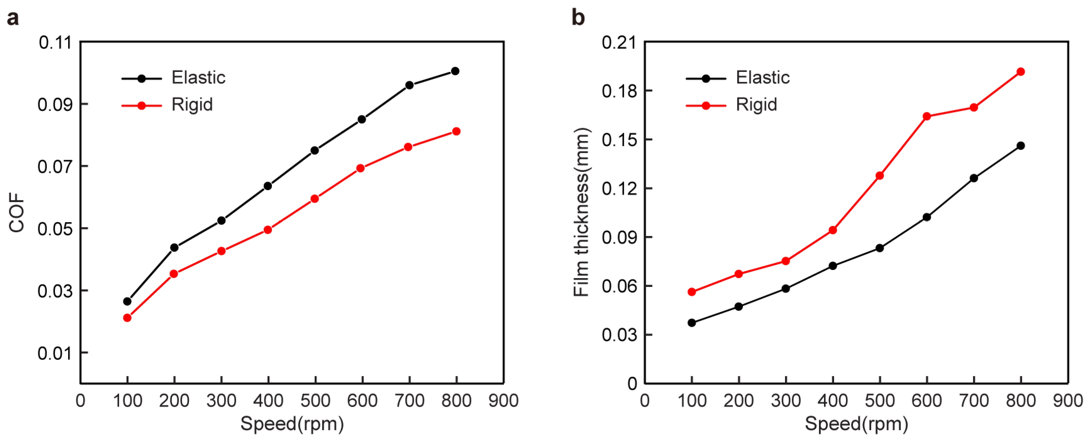
The friction coefficient of the elastic friction pair with a texture was larger than that of the rigid friction pair with a texture in
Figure 14. When the rotational speed was small, the difference in the friction coefficients between the two was small. With the increase in rotational speed, the difference in the friction coefficients increased gradually (
Figure 14a). This was due to the elastic deformation of the elastic material wall under the oil film pressure during the lubrication process, which reduced the cross-section change of the wedge gap between the shaft and the bearing, slowed down the change of the circumferential oil film pressure, and made the friction coefficient change relatively small. On the other hand, with the increase in rotational speed, the oil film thickness increased, and the elastic deformation of the elastic material wall made the oil distribution more uniform in the circumferential direction, and the change in the minimum oil film thickness relatively decreased (
Figure 14b).
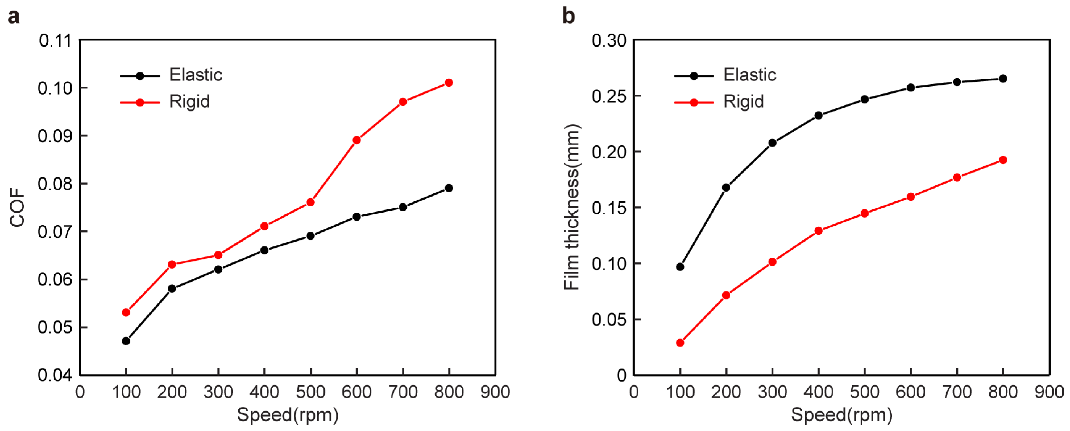
The friction coefficient of the elastic friction pair with a texture at 60° in
Figure 15 is smaller than that of the rigid friction pair with texture. When the speed was small, the friction coefficient difference between the two was small. As the speed increased, the difference in the friction coefficients gradually increased (
Figure 15a).
Although the texture parameters were different in the experiment and simulations, the ratio of the texture depth, length, and bearing radius was the same. Therefore, the trend of the experimental results is consistent with the simulation results. The distribution position of the elastic texture friction pair will affect the lubrication performance to varying degrees. When it was located at 60°, the performance was better than that of the rigid texture friction pair.


