Abstract
A direct charge nuclear battery, or DCNB, is one of the nuclear batteries based on direct energy conversion and is characterized by exceptional high voltage generation and conversion efficiency higher than other nuclear batteries. For studying potential applications of DCNB, a preliminary estimation of DCNB electrical power and performance is required; hence, conversion efficiency analysis is crucial. For preliminary verification purposes, an ideal DCNB conversion efficiency was calculated under the simplified electron transport model by using the general-purpose Monte Carlo particle transport calculation code PHITS. The result was compared with a reference experimental efficiency for a T-loaded parallel plate DCNB, and the resulting relative error was approximately 12%. Considering the relative error of 20% or less in DCNB conversion efficiency shown by preceding studies, the resulting error was comparable, and it was concluded that the PHITS code is sufficiently applicable to DCNB conversion efficiency analysis.
1. Introduction
Nuclear batteries can utilize radioactive isotopes included in spent nuclear fuels for electricity generation. In the spent fuel, Strontium and Cesium are known as major heat source elements. If they are removed together with Pu and MA recovery, the size of the geological disposal repository is expected to be significantly decreased [1]. Although the use of a fast-spectrum reactor has been proposed for the transmutation of long-lived fission products such as Se-79, Tc-99, Pd-107, and I-129 [2], the utilization of radioactive isotopes in spent nuclear fuels needs to be further investigated to reduce the environmental and social impact inherent to the geological disposal repository.
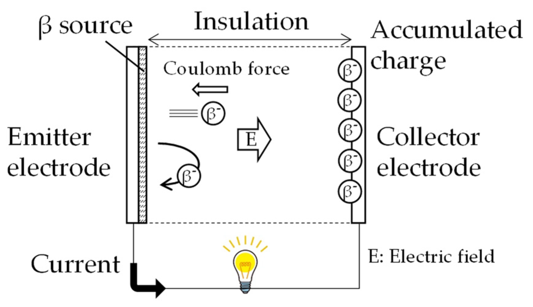
Nuclear batteries can be categorized as thermoelectric generators (also called RTG) or direct-conversion-based batteries. The latter ones mainly are β- or γ-voltaics [3,4], which are similar to photo-voltaics in terms of using semiconductors and direct charge nuclear batteries (DCNB). General principles and characteristics of these nuclear batteries are summarized in a review article [5] and in a textbook [6]. This study focuses on DCNB for its inherent simplicity in design. The principle of DCNB was developed back in 1913 [7] and summarized in a textbook [8]. DCNB essentially consists of two electrodes and thin α or β sources, as shown in Figure 1. The kinetic energy of the charged particles is directly converted into electrical energy by an electric field. Equation (1) is the example for a β particle:
where e is elementary charge, and () are kinetic energy of a β particle at the emitter and collector electrodes, and and () are electrostatic potentials at the emitter and collector electrodes. For example, keV-order particles generate kV-class high voltage. If all charged particles have identical energy and are emitted perpendicularly to the collector electrode, the efficiency of conversion from charged particle kinetic energy to electrostatic energy is 100% based on Equation (1), which is different from the Carnot cycle. Under steady-state conditions, the supply of β particles to the collector electrode needs to be balanced with the consumption of β particles at the electrode, and the voltage is generated and maintained by charges accumulated on the collector electrode. Considering insulation, lower energy β particles are preferable for stable battery operation rather than α particles with higher energy. Table 1 lists representative α and β emitters. On the other hand, the use of a thin source and the insulation gap between electrodes are unfavorable for designing batteries with high power density and small volume.
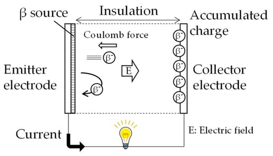
Figure 1.
Concept of a steady-state DCNB using parallel plate electrodes with a 2π β source.

Table 1.
Representative α/β emitters.
Recent studies on DCNB date back to the 2010s. A research group of the University of Illinois Urbana-Champaign (UIUC) performed theoretical, experimental, and numerical studies for H-3 (T)-loaded DCNB using parallel plate electrodes with a 2π source [9] and 147Pm-loaded DCNBs using parallel plate electrodes with a 2π source and cylindrical electrodes with a 4π source [9,10]. UIUC used Geant4 code [11], a toolkit developed by CERN for Monte Carlo simulations of the passage of particles or radiation through matter, for conversion efficiency calculation and showed a 20% difference between experimental 3.5% and numerical 4.2% efficiencies for the 147Pm-loaded DCNB using parallel plate electrodes. In the Geant4 code simulation, dominant loss effects on conversion efficiency, such as electron transport in the 147Pm source, geometrical electron leakage, Coulomb repulsion, electron backscattering, and secondary electron production at the collector electrode, were considered. A numerical optimization of the conversion efficiency of DCNB using a 4π 63Ni source and parallel plate electrodes was performed using SuperMC code [12], a CAD-based Monte Carlo program developed by the Fusion Design Study team in China for integrated simulation of nuclear systems. The calculation showed an ideal efficiency of over 20% [13]. Another approach to estimating ideal conversion efficiency was made by using only theoretical and empirical models of electron transport for 63Ni-loaded DCNB using parallel plate electrodes with a 2π source [14,15,16]. The result showed the largest difference of 18.8% between experimental 6.4% and numerical 8.2% efficiencies. All the preceding studies reviewed here focused only on the scientific investigation of DCNB conversion efficiency, which is required before proposing a promising application of DCNB. However, DCNB is characterized by its inherent simplicity in design compared to RTG and β- or γ-voltaics, which require a thermoelectric transducer and semiconductor, respectively. For designing batteries with a long-life and low power density, DCNB is still worth studying.
For studying potential applications of DCNB, a preliminary estimation of the electrical power and performance of DCNB is required; hence, conversion efficiency analysis is crucial. This work presents preliminary verification of a methodology for calculating DCNB steady-state conversion efficiency by using Particle and Heavy Ion Transport code System PHITS [17], a general-purpose Monte Carlo particle transport calculation code developed under collaboration between JAEA, RIST, KEK, and several other institutes. MC-based methodology is useful due to its applicability to any geometrical configurations, i.e., planer, cylindrical, and spherical DCNBs, so it is beneficial to have another MC-code that is applicable to DCNB conversion efficiency analysis in addition to the Geant4 code for benchmark studies. Since there have been a few examples of DCNB conversion efficiency calculation by using the PHITS code [18] and no verification research has been reported, this work preliminarily confirmed the applicability of the PHITS code to DNCB analysis by reproducing an ideal conversion efficiency using the PHITS code and comparing it with an experimental one. Experimental result of UIUCs T-loaded in parallel plates DCNB [9] was used as the reference because most of experimental conditions are available.
2. Methods
2.1. The Definition of DCNB Steady State Conversion Efficiency
Steady state conversion efficiency of a DCNB is defined by the ratio of converted electrical energy to thermal energy generated from a β source . If β particles with an average energy of are emitted in a β source, . On the other hand, if β particles out of the source particles arrive at the collector electrode, the converted electrical energy can be calculated as . The conversion efficiency can be calculated by taking the ratio:
where V is steady-state voltage between the electrodes, i.e., , and is the probability of a source β particle to arrive at the collector at steady state voltage V, which is defined by:
where depends on the steady-state voltage V between the electrodes. The probability can be further decomposed to:
where is the number of β particles escaped from the source layer out of the source particles. The is the probability of a source β particle to escape from the source layer in the direction to the collector electrode and it depends on the interaction between β particles and source layer material. The is the probability of a β particle which escaped from the source layer to cross the electric field between electrodes and it depends only on steady-state voltage V.
2.2. Calculation Model
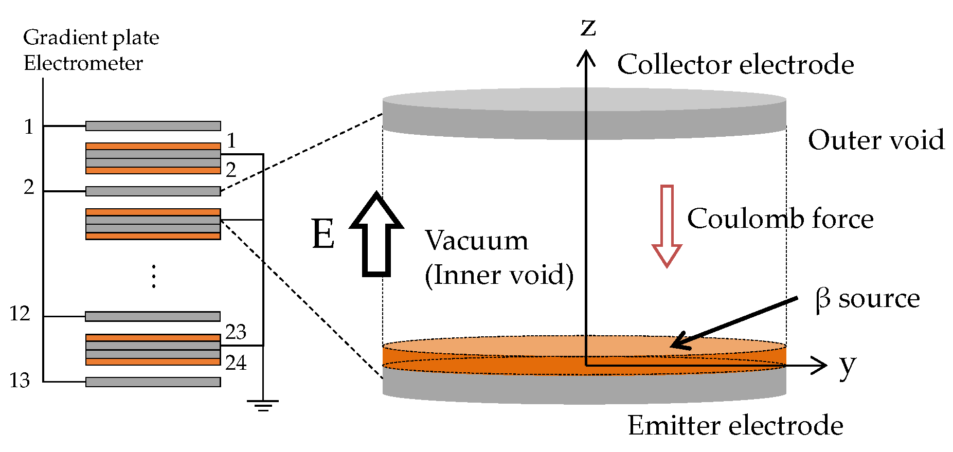
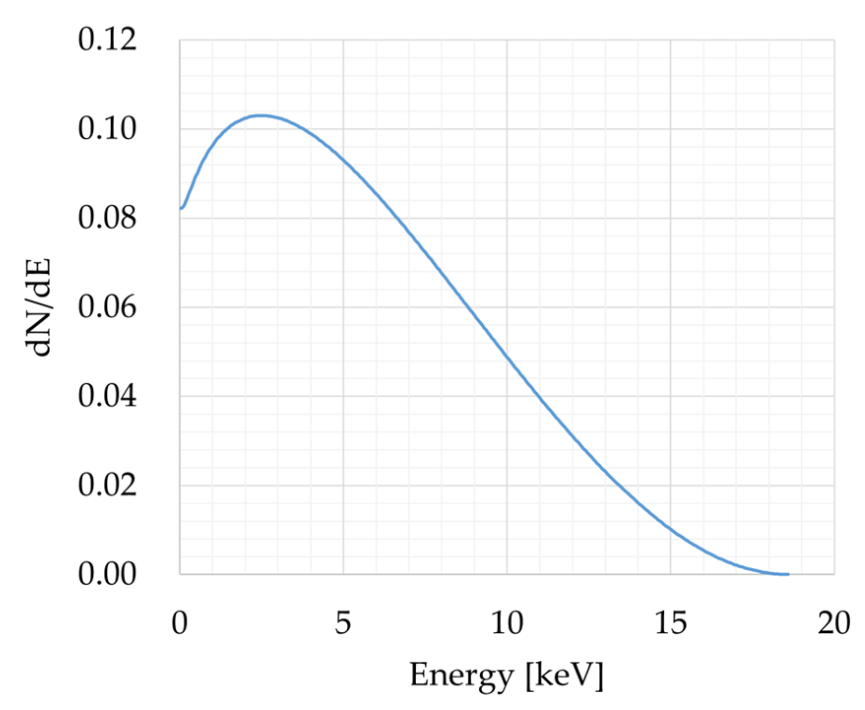
The calculation model used for the preliminary verification is shown on the right-hand side of Figure 2. In the reference UIUC T-loaded parallel plates DCNB experiment, 24 sources (emitter electrodes) and 13 stainless steel collector electrodes were used. The reproduction calculation modeled only a unit cell consisting of a pair of emitter and collector electrodes. The specifications of the model are the same as in the reference experiment. T was used as β source in the chemical form of ScT2. The energy spectrum of β particles emitted from T is shown in Figure 3 [19]. The polyimide coating of 0.3–0.4 μm on the collector electrode, which was used for suppressing secondary and backscattering electrons in the UIUC experiment, was ignored for calculating an ideal conversion efficiency . The gap between electrodes was at a pressure lower than 10−5 Torr in the UIUC experiment but was changed to an inner void in this study.
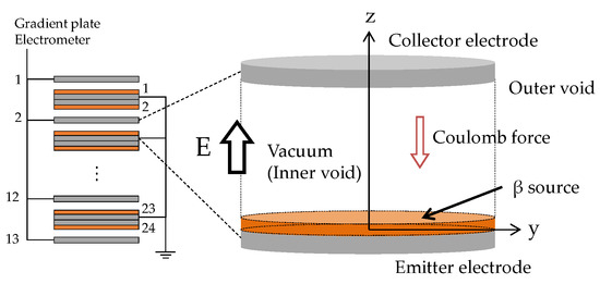
Figure 2.
Calculation model of a unit cell of the UIUC T-loaded parallel plates DCNB.
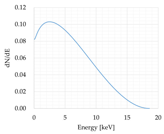
Figure 3.
An example of energy spectrum of β particles emitted from T [19].
2.3. Calculation Methodology
The PHITS code was used for calculating in Equation (3) and in Equation (4) for reproducing the conversion efficiency of the reference UIUC experiment. The PHITS code is a general-purpose Monte Carlo particle transport simulation code developed under collaboration between JAEA, RIST, KEK, and several other institutes. It can deal with the transport of all particles over wide energy ranges, using several nuclear reaction models and nuclear data libraries.
In the beginning of the calculation, β particles were generated uniformly and isotropically in the β source layer in Figure 2. The initial energy of each source β particle was decided based on an energy spectrum of the β source element. Transport calculation of the source β particles in the β source layer and in the uniform electric field between electrodes was performed by changing the voltage between electrodes from 0.0 to 20.0 kV. The electron transport model used in the PHITS code is continuous-slowing-down approximation (CSDA), including the electron density effect on stopping power, which is the same with the EGS5 code [20], a general-purpose package for the Monte Carlo simulation of the coupled transport of electrons and photons in an arbitrary geometry for particles with energies ranging from a few keV up to several TeV. CSDA is based on the Bethe-Bloch formula and takes the atomic properties of the source layer material (atomic number, atomic mass, mass density) into account in the calculation. The effect of the electron density of the source layer material on stopping power, i.e., the polarization effect made by source β particles in the source layer, is also considered. Secondary and backscattering electrons on the surface of the collector electrode are included in the PHITS calculation. However, for estimating an ideal conversion efficiency , the secondary electrons and backscattered β particles were not taken into account in the calculation. In the reproduction calculation, an ideal conversion efficiency and the probability were compared with the reference experiment result and condition. Reproduction calculation conditions are summarized in Table 2 and are compared to conditions used in the reference UIUC experiment.
Table 2.
Reproduction calculation conditions compared to conditions used in the UIUC reference experiment.
2.4. The Reference Experiment Methodology
As described in Section 2.2, the reference experiment used a multilayer T-loaded parallel plates DCNB, as shown on the left-hand side of Figure 2. Detailed experimental conditions and results are opened to the public through a reference [9], and important specifications of the experimental DCNB are summarized in Table 2. In the reference experiment by UIUC, the probability in Equation (4) was calculated, and then short circuit current , saturation voltage , and leakage resistance were measured for estimating the optimum conversion efficiency. In the following subsections, the calculation and measurement processes are summarized.
2.4.1. Calculation of the Probability
The probability of a source β particle escaping from the source layer in the direction of the collector electrode, , can be calculated by:
where is the specific activity in the source layer [Bq/mg] and D is the mass thickness of the layer [mg/cm2]. The is the β particles current density on the surface of the source layer [A/cm2] with and D. For a thin plane source layer, the current density is theoretically given by [9,21]:
where is the average energy of source β particles, is the corresponding power density of the β particles on the surface of the source layer, is the energy absorbed in a β particle travel dr, is a distance parameter and is an azimuthal parameter in the integration. In Equation (6), the following working expression of in the spherical layer with radius r was used [9,22]:
where r is the radius in unit of mass thickness [mg/cm2]; is the mass absorption coefficient [cm2/mg]; is the stopping power near the source [keVcm2/mg]. It should be noted that the of Equation (5) depends only on the mass thickness of source layer D because the is proportional to the specific activity based on Equation (6). In the UIUC experiment, the probability was calculated using Equation (5) through (7) for scandium tritide with the mass density of 2.9 g/cm3, the thickness of 300 nm, of 15.1 cm2/mg, and of 56.6 keVcm2/mg.
2.4.2. Estimation of the Optimum Conversion Efficiency
Following the measurement of short circuit current , saturation voltage , and leakage resistance , the dependencies of and on the resistance of electrical load connected to the battery were calculated based on the following equation:
where and are the internal resistance and the load resistance of the battery, is load current, and is the open-circuit voltage. The highest electrical power of approximately 200 μW, which was calculated by , was obtained if the was set to 35 GΩ. The corresponding at of 35 GΩ was 2.6 kV. For calculating the optimum conversion efficiency, the source radioactivity Asource used in the experiment was estimated by using the measured short circuit current of 148 nA and a calculated of 0.23 for the 300 nm ScT2 source thickness:
where it is noted that in Equation (11) is equivalent to the measured short circuit current. The optimum conversion efficiency was then calculated by taking the ratio of 200 μW to the source thermal power:
where the average energy of a source β particle emitted from T is 5.7 keV.
3. Results and Discussion
Table 3 compares in Equation (4) calculated with and without SUS-304 emitter electrode. The use of the SUS-304 emitter electrode increased the by 5.4% by reflecting β particles toward the collector electrode. The UIUC condition of 0.23 is a theoretical estimation, not a measured result, and does not include the reflection effect. In the UIUC experiment, ScT2 radioactivity Asource, i.e., thermal power, was estimated directly using the theoretical value of 0.23. This means that the estimation assumed only 23% of source β particles escaped from the source layer. Therefore, ScT2 thermal power was overestimated in the experiment. If the reflection effect of 5.4% is assumed, in the UIUC condition is increased to 0.24, and the experimental conversion efficiency is increased to 5.80% compared to the original result of 5.5% at 2.6 kV. Since current and voltage were directly measured in the UIUC experiment, both of them included the reflection effect, and there was no impact on the estimated highest electrical power of 200 μW.
Table 3.
Probability of β particles escaping from the source layer at 300 nm source thickness.
The steady-state conversion efficiency and calculated by the PHITS code are shown in Figure 4a. Following the voltage increase, decreases due to Coulomb repulsion. On the other hand, electrostatic energy converted from the kinetic energy of β particles increases. According to these two competing effects, the conversion efficiency is upper-curved and becomes the maximum of 6.48% (σ: 0.001%) at 3.0 kV, which has a relative error of 17.9% to the UIUC original experimental result of 5.5% at 2.6 kV and 11.9% to the corrected efficiency of 5.80%. The residual error will be attributed to no consideration of secondary, backscattering, or leakage electrons at the collector electrode in the reproduction calculation. Considering the relative error of 20% or less in DCNB conversion efficiency shown by preceding studies, the 11.9% relative error is comparable, and the PHITS code is sufficiently applicable to DCNB conversion efficiency analysis. The difference in the optimum voltage of 0.4 kV, which is equivalent to an energy increase of 0.4 keV, would be attributed to the complete vacuum condition between electrodes in the calculation. The optimum voltage depends on the energy and angular distribution of β particles escaping from the source layer. The energy spectrum of the escaped β particles, which is normalized to a single escaped β particle, is shown in Figure 4b. The spectrum was calculated on the upper surface of the β source layer. According to the spectrum, one can expect that the optimum voltage will be between 3.0 and 5.0 kV. It should be noted that the spectrum is shifted to the right of the initial spectrum of source β particles. The average energy of the escaped β particles is 6.48 keV, compared to 5.70 keV for the source β particles. This is because β particles with lower energy are self-absorbed in the source layer and are not able to escape from the source.
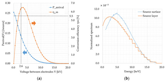
Figure 4.
(a) Conversion efficiency of the reference T-loaded DCNB; (b) Normalized spectrum of β particles escaped from the source layer. There is no escaped β particles with energy lower than 1.0 keV due to the PHTIS code cut-off energy setting.
The conversion efficiency η of DCNB is known to be relatively higher than that of other types of nuclear batteries such as RTG, β- and γ-voltaics. The combinational use of cylindrical or spherical electrodes and 4-π sources will further increase the efficiency. In fact, η of 14% has already been achieved by experiment [9], where a thin planer 4-π source of Pm-147 was placed at the center of a surrounding cylindrical collector electrode coated with polyimide insulation for increasing and . Applications of nuclear batteries are not limited to space missions and have been proposed in the emerging fields of isolated sensors and wireless network systems [4,23]. Even though the kV-class optimum voltage of DCNB will require a step-down transformer for conventional electrical devices, DCNB will be suitable and applicable as a low-power long-life battery to isolated harsh environments such as the deep seabed or the geographic poles for long-term monitoring operations.
4. Conclusions
This work presented preliminary verification of a methodology for calculating DCNB steady-state conversion efficiency by using the PHITS code. It was confirmed that the efficiency reproduced by the PHITS code for the reference UIUC T-loaded parallel plates DCNB had a relative error of 11.9%, which was comparable to the relative error of 20% or less in DCNB conversion efficiency shown by preceding studies using other Monte Carlo codes or theoretical estimations. This means that the PHITS code is sufficiently applicable to the DCNB conversion efficiency analysis. Consideration of secondary, backscattering, and leakage electrons at the collector electrode will further improve DCNB efficiency calculations.
Author Contributions
Conceptualization, H.T.; methodology, H.T.; software, H.T., R.K. and H.U.; validation, H.T., R.K. and H.U.; formal analysis, H.T.; investigation, H.T.; resources, H.T.; data curation, H.T.; writing—original draft preparation, H.T.; writing—review and editing, H.T., F.T., Y.U. and K.T.; visualization, H.T.; supervision, H.T., F.T., Y.U. and T.K.; project administration, H.T. All authors have read and agreed to the published version of the manuscript.
Funding
This research was funded by the Uchida Energy Science Promotion Foundation, grant number R06-1007.
Data Availability Statement
Data are contained within the article.
Conflicts of Interest
The authors declare no conflicts of interests.
References
- Nishihara, K.; Nakayama, S.; Morita, Y.; Oigawa, H.; Iwasaki, T. Impact of Partitioning and Transmutation on LWR High-Level Waste Disposal. J. Nucl. Sci. Technol. 2008, 45, 84–97. [Google Scholar] [CrossRef]
- Wakabayashi, T.; Tachi, Y.; Takahashi, M.; Chiba, S.; Takaki, N. Study on method to achieve high transmutation of LLFP using fast reactor. Sci. Rep. 2019, 9, 19156. [Google Scholar] [CrossRef] [PubMed]
- Olsen, L.C.; Cabauy, P.; Elkind, B.J. Betavoltaic power sources. Phys. Today 2012, 65, 35–38. [Google Scholar] [CrossRef]
- Terranova, M. Nuclear batteries: Current context and near-term expectations. Int. J. Energy Res. 2022, 46, 19368–19393. [Google Scholar] [CrossRef]
- Prelas, M.A.; Weaver, C.L.; Watermann, M.L.; Lukosi, E.D.; Schott, R.J.; Wisniewski, D.A. A review of nuclear batteries. Prog. Nucl. Energy 2014, 75, 117–148. [Google Scholar] [CrossRef]
- Prelas, M.; Boraas, M.; De La Torre Aguilar, F.; Seelig, J.-D.; Tchouaso, M.T.; Wisniewski, D. Nuclear Batteries and Radioisotopes; Springer: Cham, Switzerland, 2016. [Google Scholar]
- Moseley, H. The Attainment of High Potentials by the Use of Radium. Proc. R. Soc. Lond. 1913, A88, 471–476. [Google Scholar]
- Miley, G. Direct Conversion of Nuclear Radiation Energy; American Nuclear Society: La Grange Park, IL, USA, 1970. [Google Scholar]
- Yukabova, G.N. Nuclear Batteries with Tritium and Promethium-147 Radioactive Sources. Ph.D. Thesis, University of Illinois at Urbana-Champaign, Urbana, IL, USA, 2010. [Google Scholar]
- Kavetskiy, A.; Yakubova, G.; Yousaf, S.; Bower, K.; Robertson, J.; Garnov, A. Efficiency of Pm-147 direct charge radioisotope battery. Appl. Radiat. Isot. 2011, 69, 744–748. [Google Scholar] [CrossRef] [PubMed]
- Agostinelli, S.; Allison, J.; Amako, K.; Apostolakis, J.; Araujo, H.; Arce, P.; Asai, M.; Axen, D.; Banerjee, S.; Barrand, G.; et al. Geant4—A Simulation Toolkit. Nucl. Instrum. Methods Phys. Res. Sect. A 2003, 506, 250–303. [Google Scholar] [CrossRef]
- Wu, Y.; Song, J.; Zheng, H.; Sun, G.; Hao, L.; Long, P.; Hu, L. CAD-based Monte Carlo program for integrated simulation of nuclear system SuperMC. Ann. Nucl. Energy 2015, 82, 161–168. [Google Scholar] [CrossRef]
- Wang, X.; Han, Y.; Zhang, J.; Li, Z.; Li, T.; Zhao, X.; Wu, Y. The design of a direct charge nuclear battery with high energy conversion efficiency. Appl. Radiat. Isot. 2019, 148, 147–151. [Google Scholar] [CrossRef] [PubMed]
- Haim, Y.; Marciano, Y.; Debotton, G. Tunable direct beta-radiation harvester at the nanowatt scale. Sens. Actuators A Phys. 2018, 283, 228–234. [Google Scholar] [CrossRef]
- Haim, Y.; Debotton, G. Experimental Study of the Direct-Charge Beta Radiation Method for Energy Harvesting. IEEE Trans. Electron Devices 2020, 67, 5076–5081. [Google Scholar] [CrossRef]
- Haim, Y.; Debotton, G. Performance Analysis of the Direct-Charge β-Radiation Energy-Harvesting Method. IEEE Trans. Electron Devices 2021, 68, 2917–2925. [Google Scholar] [CrossRef]
- Iwamoto, Y.; Hashimoto, S.; Sato, T.; Matsuda, N.; Kunieda, S.; Çelik, Y.; Furutachi, N.; Niita, K. Benchmark study of particle and heavy-ion transport code system using shielding integral benchmark archive and database for accelerator-shielding experiments. J. Nucl. Sci. Technol. 2022, 59, 665–675. [Google Scholar] [CrossRef]
- Takezawa, H.; Kikuchi, T.; Otsu, N.; Nomura, A.; Uchida, Y.; Tamura, F. Preliminary Study on Conversion Efficiency of Direct Charge Nuclear Batteries Using Beta Sources for Low-Power Long-Life Battery Applications. In Proceedings of the 1st KOSEN Research International Symposium (KRIS2023), Tokyo, Japan, 1–2 March 2023. [Google Scholar]
- Live Chart of Nuclides. Available online: https://www-nds.iaea.org/relnsd/vcharthtml/VChartHTML.html (accessed on 19 January 2024).
- Hirayama, H.; Namito, Y.; Nelson, W.R.; Bielajew, A.F.; Wilderman, S.J.; Michigan, U. The EGS5 Code System. SLAC-R-730 and KEK Report 2005-8. 2005. Available online: https://rcwww.kek.jp/research/egs/egs5_manual/slac730-160113.pdf (accessed on 12 May 2024).
- Kavetsky, A.G.; Nekhoroshkov, S.N.; Meleshkov, S.P.; Kaminski, Y.L.; Akulov, G.P. Radioactive Materials, Ionizing Radiation Sources, and Radioluminescent Light Sources for Nuclear Batteries. In Polymers, Phosphors, and Voltaics for Radioisotope Microbatteries, 1st ed.; Bower, K.E., Barbanel, Y.A., Shreter, Y.G., Bohnert, G.W., Eds.; CRC Press: Boca Raton, FL, USA, 2002; pp. 39–108. [Google Scholar]
- Bochkarev, V.; Radzievsky, G.; Timofeev, L.; Demianov, N. Distribution of absorbed energy from a point beta source in a tissue-equivalent medium. Int. J. Appl. Radiat. Isot. 1972, 23, 493–497. [Google Scholar] [CrossRef] [PubMed]
- Walton, R.; Anthony, C.; Ward, M.; Metje, N.; Chapman, D. Radioisotopic battery and capacitor system for powering Wireless Sensor Networks. Sens. Actuators A Phys. 2013, 203, 405–412. [Google Scholar] [CrossRef]

Disclaimer/Publisher’s Note: The statements, opinions and data contained in all publications are solely those of the individual author(s) and contributor(s) and not of MDPI and/or the editor(s). MDPI and/or the editor(s) disclaim responsibility for any injury to people or property resulting from any ideas, methods, instructions or products referred to in the content. |
© 2024 by the authors. Licensee MDPI, Basel, Switzerland. This article is an open access article distributed under the terms and conditions of the Creative Commons Attribution (CC BY) license (https://creativecommons.org/licenses/by/4.0/).