
Accuracy Analysis of Complex Transmission System with Distributed Tooth Profile Errors

Abstract
:1. Introduction
2. Geometric Model of Complex Transmission System Containing Distributed Tooth Profile Errors
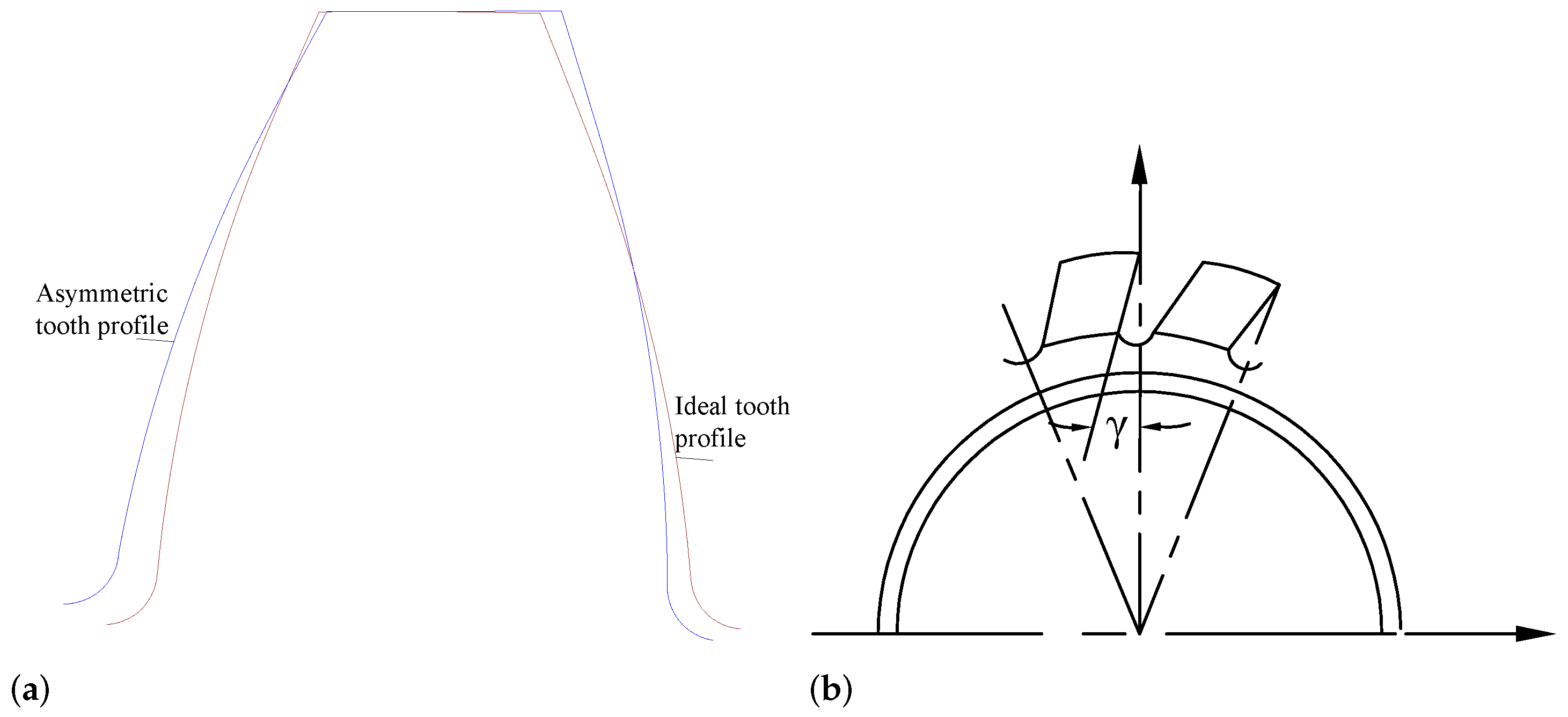
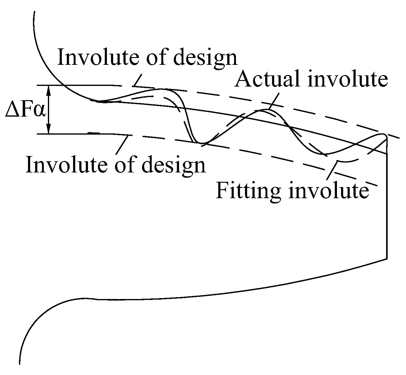
2.1. Modeling of Involute Tooth Profile Error
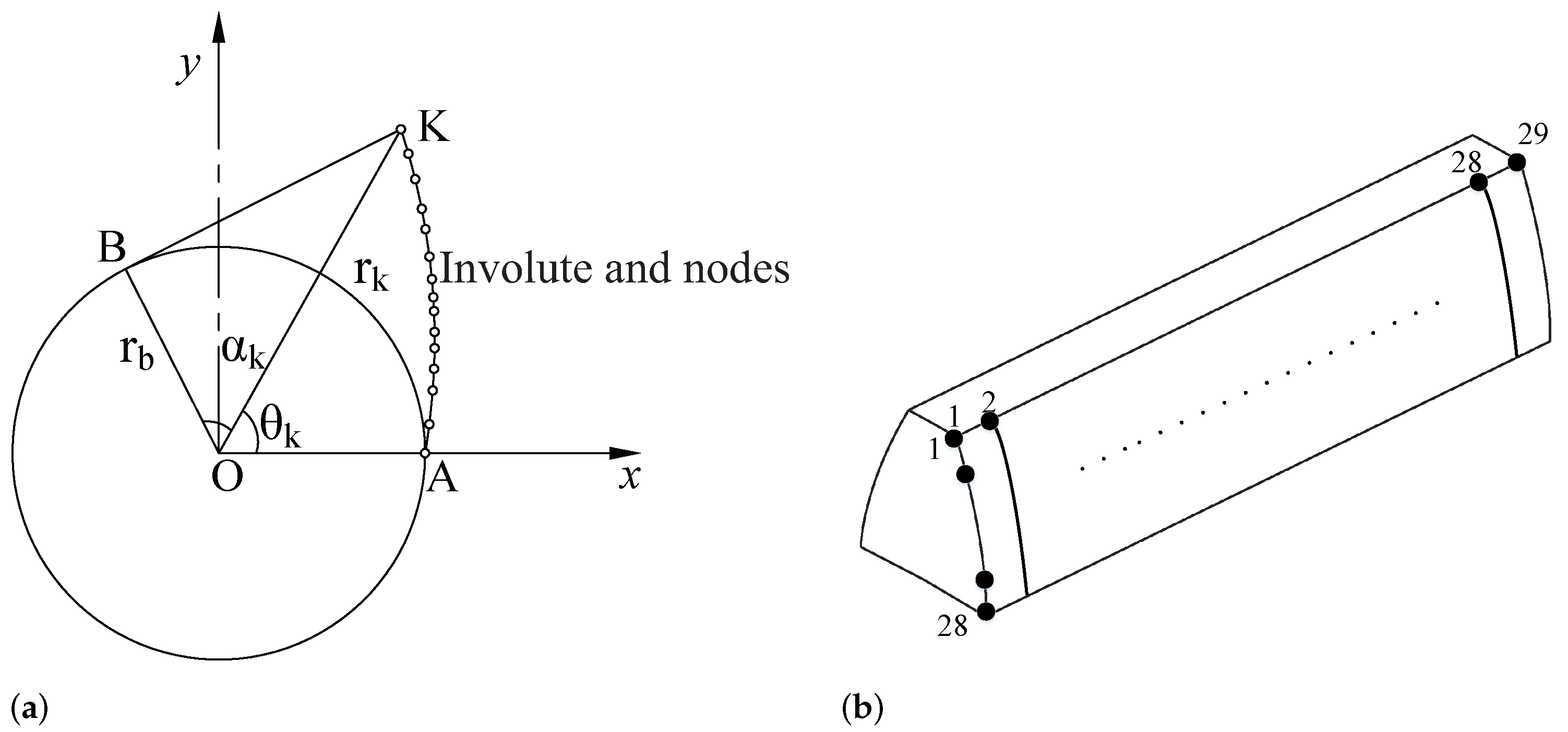
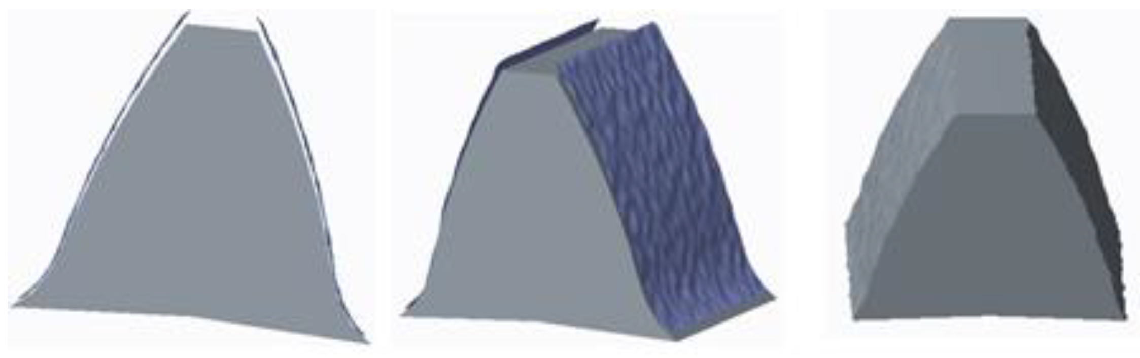
2.2. Generation of Error Tooth Surface
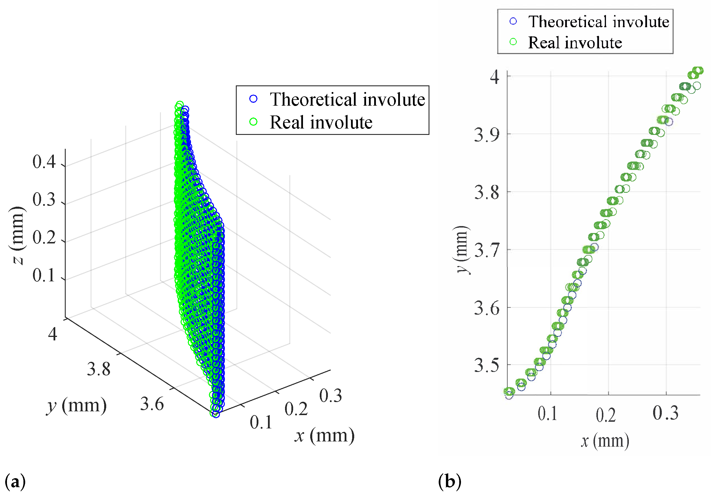
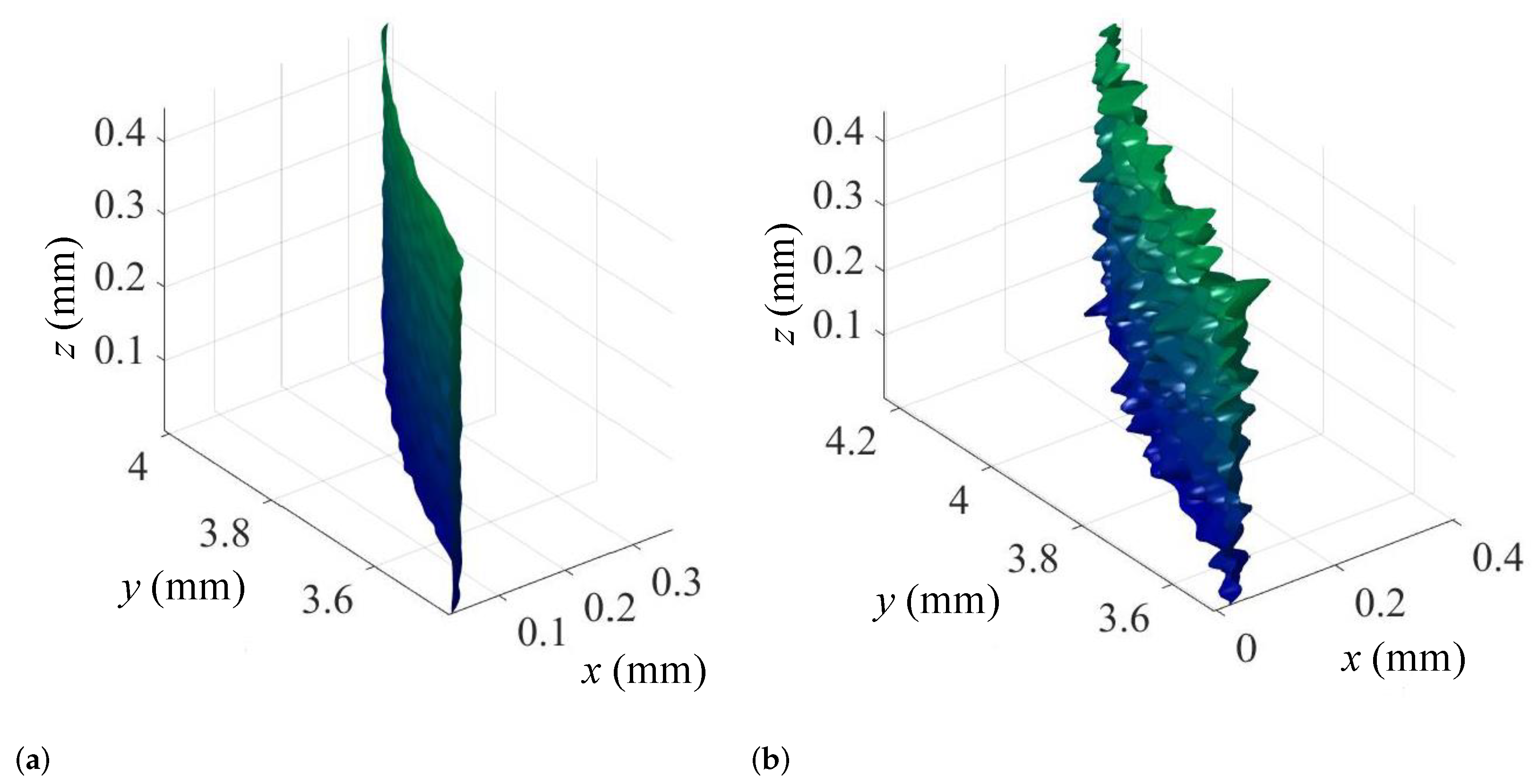
2.3. Verification of Surface Modeling Accuracy
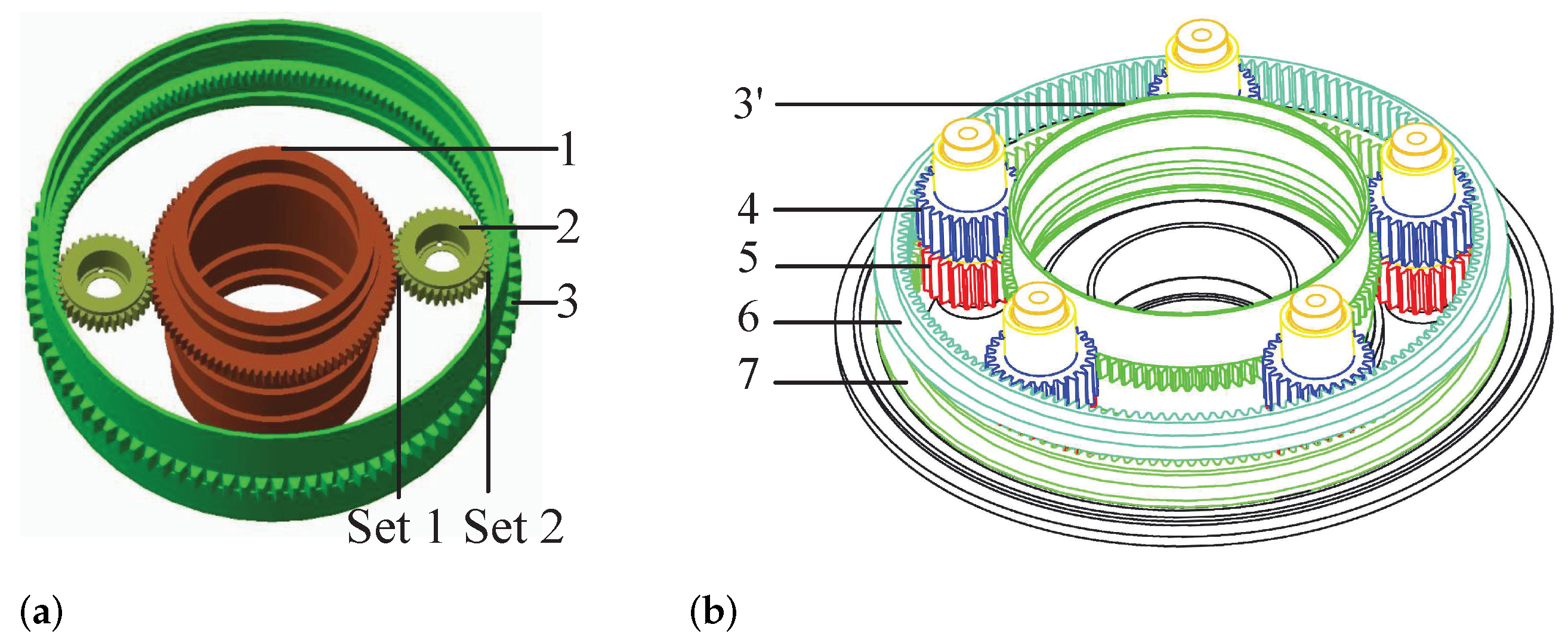
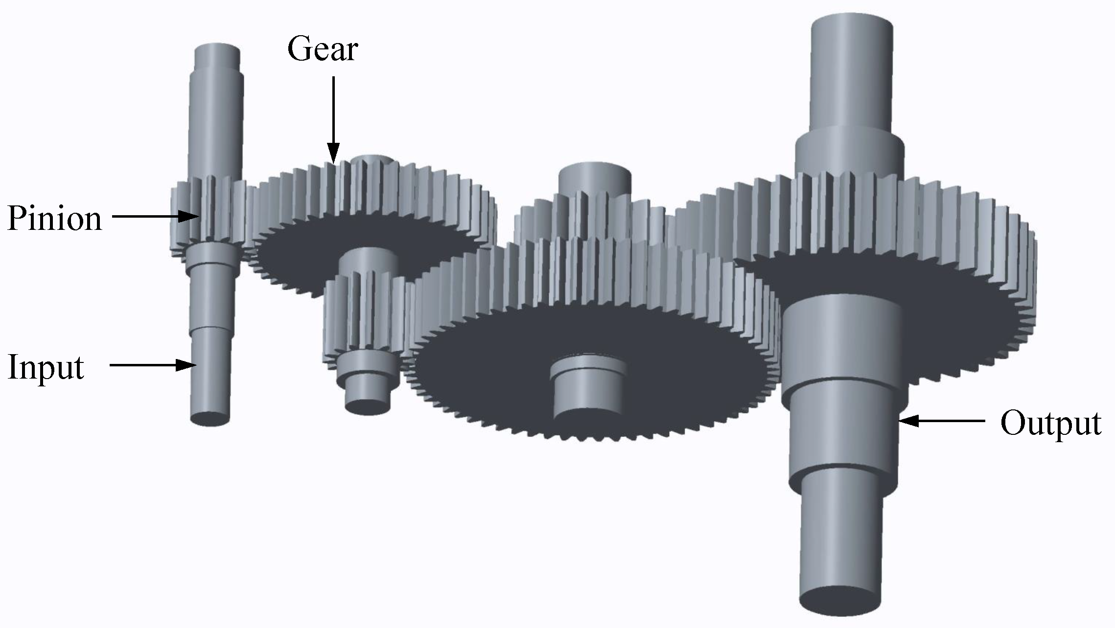
2.4. Geometric Model of Complex Transmission System
3. Finite Element Dynamic Model
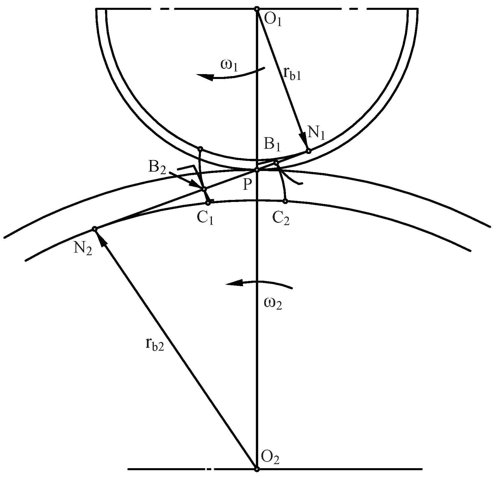
3.1. Influence of Distributed Tooth Profile Error on Contact Stress
3.2. Influence of Distributed Tooth Profile Error on Transmission Accuracy
4. Experiment
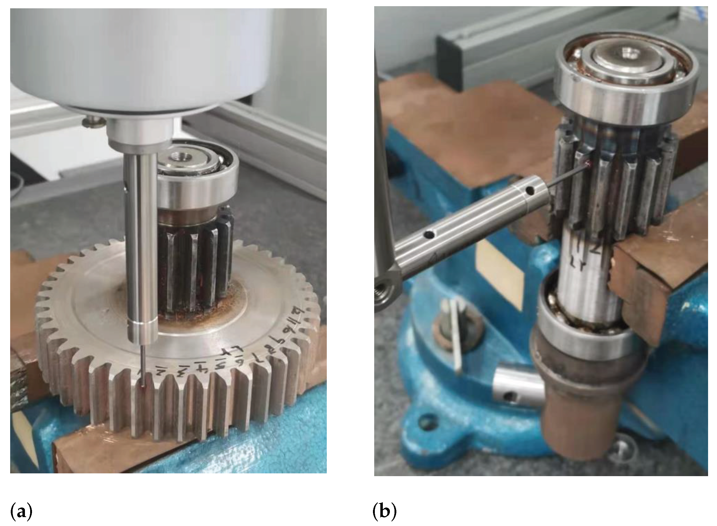
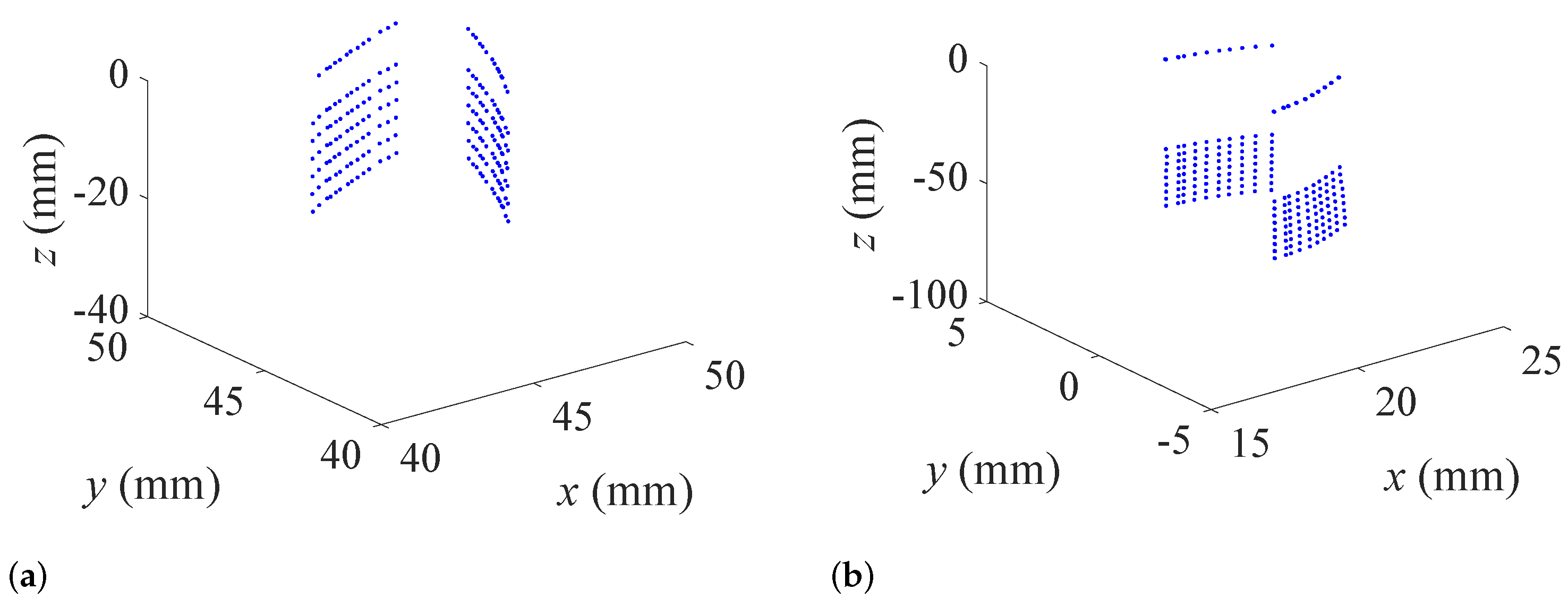
4.1. Measurement of Gear Tooth Surfaces
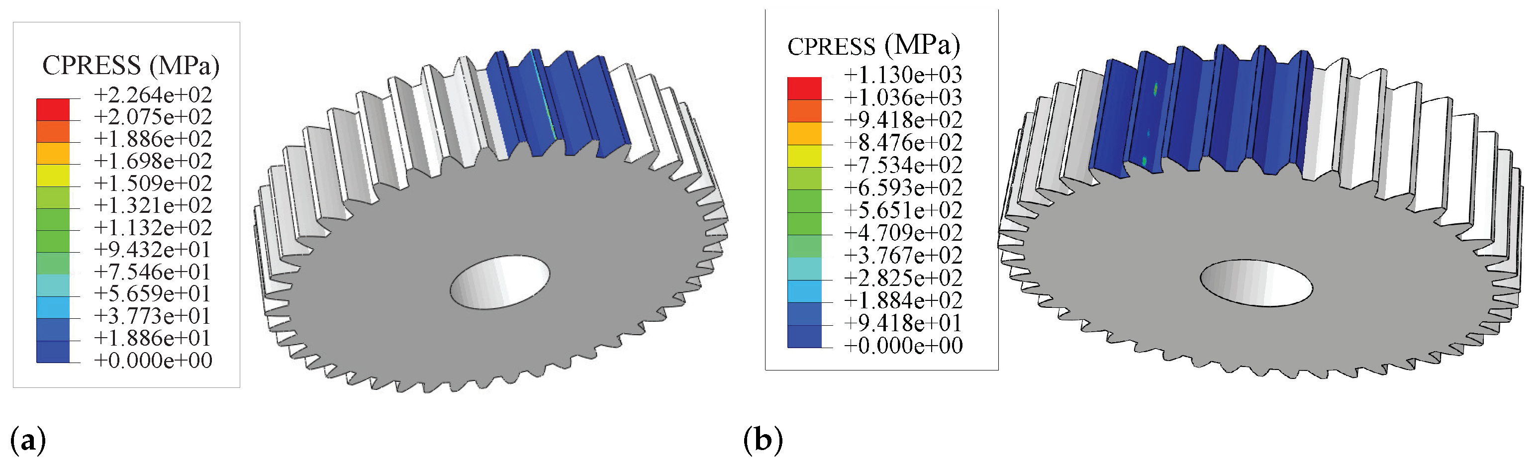
4.2. Finite Element Analysis of Measured Gears
5. Discussion
6. Conclusions
Author Contributions
Funding
Data Availability Statement
Conflicts of Interest
References
- Wang, J.; Wang, S.; Ma, C.; Xia, C. Crucial errors identification of worm grinding process of face gears based on tooth flank posture error model and their influences on tooth flank errors. Int. J. Adv. Manuf. Technol. 2022, 119, 6177–6192. [Google Scholar] [CrossRef]
- Karma, V.K.; Maheshwari, G. Determination of Transmission Error and Mesh Stiffness in Spur Gear Pair Using CAD-FEM Integration Approach; IOP Publishing Ltd.: Tamil Nadu, India, 2023. [Google Scholar] [CrossRef]
- Pedrero, J.I.; Sánchez, M.B.; Pleguezuelos, M. Analytical model of meshing stiffness, load sharing, and transmission error for internal spur gears with profile modification. Mech. Mach. Theory 2024, 197, 105650. [Google Scholar] [CrossRef]
- Velex, P.; Chapron, M.; Fakhfakh, H.; Bruyère, J.; Becquerelle, S. On transmission errors and profile modifications minimising dynamic tooth loads in multi-mesh gears. J. Sound Vib. 2016, 379, 28–52. [Google Scholar] [CrossRef]
- Chen, H.; Zhu, Y.; Mao, J.; Wang, X. Influence of tooth profile modification on design transmission error of involute spur gear. J. Huazhong Univ. Sci. Technol. (Natural Sci. Ed.) 2018, 46, 91–97. [Google Scholar] [CrossRef]
- Sanchez, M.B.; Pleguezuelos, M.; Pedrero, J.I. Influence of profile modification on the transmission error of spur gears under surface wear. Mech. Mach. Theory 2024, 191, 105473. [Google Scholar] [CrossRef]
- Chen, Z.; Ji, P. Research on the variation of mesh stiffness and transmission error for spur gear with tooth profile modification and wear fault. Eng. Fail. Anal. 2020, 122, 105184. [Google Scholar] [CrossRef]
- Zhou, D.; Guo, Y.; Yang, J.; Zhang, Y. Study on the Parameter Influences of Gear Tooth Profile Modification and Transmission Error Analysis. Machines 2024, 12, 316. [Google Scholar] [CrossRef]
- Zhang, M.; Zhang, Z.; Shi, L. A new assembly error modeling and calculating method of complex multi-stage gear transmission system for a large space manipulator. Mech. Mach. Theory 2020, 153, 103982. [Google Scholar] [CrossRef]
- Ottewill, J.R.; Neild, S.A.; Wilson, R.E. An investigation into the effect of tooth profile errors on gear rattle. J. Sound Vib. 2010, 329, 3495–3506. [Google Scholar] [CrossRef]
- Tuplin, W.A. Gear Design, 1st ed.; Machinery Publishing Co. Ltd.: London, UK, 1962. [Google Scholar]
- Xun, C.; Long, X.; Hua, H. Effects of random tooth profile errors on the dynamic behaviors of planetary gears. J. Sound Vib. 2018, 415, 91–110. [Google Scholar] [CrossRef]
- Gregory, R.W.; Harris, S.L.; Munro, R.G. Dynamic Behaviour of Spur Gears. Proc. Inst. Mech. Eng. 1963, 178, 207–226. [Google Scholar] [CrossRef]
- Theodossiades, S.; Natsiavas, S. Periodic and chaotic dynamics of motor-driven gear-pair systems with backlash. Chaos Solitons Fractals 2001, 12, 2427–2440. [Google Scholar] [CrossRef]
- Özgüven, H.; Houser, D.R. Dynamic analysis of high speed gears by using loaded static transmission error. J. Sound Vib. 1988, 125, 71–83. [Google Scholar] [CrossRef]
- Mark, W.D. Use of the generalized transmission error in the equations of motion of gear systems. J. Mech. Des. Trans. ASME 1987, 109, 283–291. [Google Scholar] [CrossRef]
- Liu, C.; Qin, D.; Liao, Y. Dynamic model of variable speed process for herringbone gears including friction calculated by variable friction coefficient. J. Mech. Des. Trans. ASME 2014, 136, 041006. [Google Scholar] [CrossRef]
- Yuan, B.; Chang, S.; Liu, G. Quasi-static analysis based on generalized loaded static transmission error and dynamic investigation of wide-faced cylindrical geared rotor systems. Mech. Mach. Theory 2019, 134, 74–94. [Google Scholar] [CrossRef]
- Yuan, B.; Chang, L.; Liu, G. An efficient three-dimensional dynamic contact model for cylindrical gear pairs with distributed tooth flank errors. Mech. Mach. Theory 2020, 152, 103930. [Google Scholar] [CrossRef]
- Bonori, G.; Pellicano, F. Non-smooth dynamics of spur gears with manufacturing errors. J. Sound Vib. 2007, 306, 271–283. [Google Scholar] [CrossRef]
- Wang, Q.; Zhang, Y. A model for analyzing stiffness and stress in a helical gear pair with tooth profile errors. J. Vib. Control. 2016, 23, 272–289. [Google Scholar] [CrossRef]
- Wang, Q. An Investigation for Analyzing the Dynamic Characteristics and Fatigue Reliability of a Gear System. Ph.D. Thesis, Northeast University, Shengyang, Liaoning Province, China, 2015. [Google Scholar]
- Chen, Z.; Zhou, Z.; Zhai, W. Improved analytical calculation model of spur gear mesh excitations with tooth profile deviations. Mech. Mach. Theory 2020, 149, 103838. [Google Scholar] [CrossRef]
- Chen, Z.; Shao, Y. Mesh stiffness calculation of a spur gear pair with tooth profile modification and tooth root crack. Mech. Mach. Theory 2013, 62, 63–74. [Google Scholar] [CrossRef]
- Kim, B.S.; Jeong, S.T.; Ahn, H.J. The Prediction of the angular transmission error of a harmonic drive by measuring noncontact tooth profile and considering three-dimensional tooth engagement. Int. J. Precis. Eng. Manuf. 2023, 24, 371–378. [Google Scholar] [CrossRef]
- GB/T 10095.1-2022; Shi, Z.; Wang, Z.; Yu, B. Cylindrical gears-ISO System of Flank Tolerance Classification—Part 1: Definitions and Allowable Values of Deviations Relevant to Flanks of Gear Teeth. State Administration for Market Regulation and Standardization Administration of China, CNKI: Beijing, China, 2022.
- Liu, X. (Ed.) Involute Cylindrical Gear; China Planning Press: Beijing, China, 2004. [Google Scholar]
- Zhang, Z.; Zhang, Z.; Jin, X. A novel modelling method of geometric errors for precision assembly. Int. J. Adv. Manuf. Technol. 2017, 94, 1139–1160. [Google Scholar] [CrossRef]
- GB/T 3480-1997; Calculation Methods of Load Capacity for Involute Cylindrical Gears. State Technology Supervision Administration, CNKI: Beijing, China, 1997.
- Hertz, H. Uber die beruhrung fester elastlseher korper. Reine Angew. Math. 1882, 92, 156–171. [Google Scholar] [CrossRef]
- Zhang, Q.; Zhang, Z.; Jin, X.; Zeng, W. Entropy-based method for evaluating spatial distribution of form errors for precision assembly. Precis. Eng. 2019, 60, 374–382. [Google Scholar] [CrossRef]
- Zhang, Q.; Xin, J.; Zhihua, L.; Zhang, Z. A new approach of surfaces registration considering form errors for precise assembly. Assem. Autom. 2020, 40, 789–800. [Google Scholar] [CrossRef]
- Zhang, Q. Research on Assembly Accuracy Prediction for Precision Instruments. Ph.D. Thesis, School of Mechanical Engineering, Beijing Institute of Technology, Beijing, China, 2020. [Google Scholar]
- Guo, H.; Zhang, Z.; Xiao, M.; Liu, H. Tolerance optimization method based on flatness error distribution. Int. J. Adv. Manuf. Technol. 2021, 113, 279–293. [Google Scholar] [CrossRef]
- Ding, H.; Zhu, L.; Xiong, Z. Survey on coordinate measurement, geometric modeling and RP or NC generation from measured data points. Chin. J. Mech. Eng. 2003, 39, 10. [Google Scholar] [CrossRef]


| Gears | Module (mm) | Number of Teeth | Width (mm) | Pressure Angle (°) |
|---|---|---|---|---|
| Gear 1 | 1 | 91 | 8 | 20 |
| Gear 2 | 1 | 35 | 9 | 20 |
| Gear 3 | 1 | 161 | 8 | 20 |
| Gear 3’ | 2 | 90 | 11 | 20 |
| Gear 4 | 2 | 25 | 24 | 20 |
| Gear 5 | 2 | 24 | 24 | 20 |
| Gear 6 | 2 | 140 | 22 | 20 |
| Gear 7 | 2 | 139 | 22 | 20 |
| Gears | Tooth Profile Tolerance (m) | Tooth Profile Form Error (m) | Tooth Profile Slope Deviation (m) | Tooth Line Tolerance (m) |
|---|---|---|---|---|
| Gear 1 | 8.5 | 6.5 | 5.5 | 9 |
| Gear 2 | 7.5 | 5.5 | 4.6 | 9 |
| Gear 3’ | 10 | 7.5 | 6 | 9 |
| Gear 3 | 14 | 11 | 9 | 11 |
| Gear 4 | 7.5 | 5.5 | 4.6 | 9 |
| Gear 5 | 7.5 | 5.5 | 4.6 | 9 |
| Gear 6 | 14 | 11 | 9 | 11 |
| Gear 7 | 14 | 11 | 9 | 11 |
| Gears | Masses (Kg) | Inertias (Kg· mm2) |
|---|---|---|
| Gear 1 | 0.448 | 819 |
| Gear 2 | 0.041 | 11.1 |
| Gear 3 | 1.236 | 7070 |
| Gear 3’ | 1.236 | 7070 |
| Gear 4 | 0.7 | 356 |
| Gear 5 | 0.645 | 356 |
| Gear 6 | 1.797 | 31,100 |
| Gear 7 | 1.309 | 25,300 |
| Modeling Steps | Parameters | Numerical Value |
|---|---|---|
| Solver settings | Software | ABAQUS (Abaqus/CAE 2021) |
| Step | Dynamic | |
| Solver | Explicit | |
| Mesh | Element | C3D8R |
| Property | Ultra-high-strength stainless steel (gear) | Young’s modulus 190 GPa |
| Poisson’s ratio 0.305 | ||
| Mass density 7.9 g/cm3 | ||
| Expansion coeff 1.1 × 10⁻⁵ | ||
| Titanium alloy (carrier and shaft) | Young’s modulus 105 GPa | |
| Poisson’s ratio 0.34 | ||
| Mass density 4.51 g/cm3 | ||
| Expansion coeff 1.09 × 10⁻⁵ | ||
| Interaction | Interaction | Surface-to-surface contact (Explicit) |
| Interaction property | Coulomb friction coeff 0.1 and hard contact | |
| Constraints | Coupling and tie | |
| Boundary condition | Temperature | From −20 °C to 50 °C |
| Fixed boundary | Bottom of support | |
| Rotate or translate | Gears and shafts |
| Parameters | Calculated Contact Stress (MPa) | FEM (MPa) | Relative Error (%) | |
|---|---|---|---|---|
| Set 1 | Gear 1 | 557.8427 | 619.4 | 11.03 |
| Gear 2 | 572.0677 | 559.2 | 2.25 | |
| Set 2 | Gear 2 | 458.9514 | 426.8 | 7.53 |
| Gear 3 | 458.9514 | 556.6 | 18.99 | |
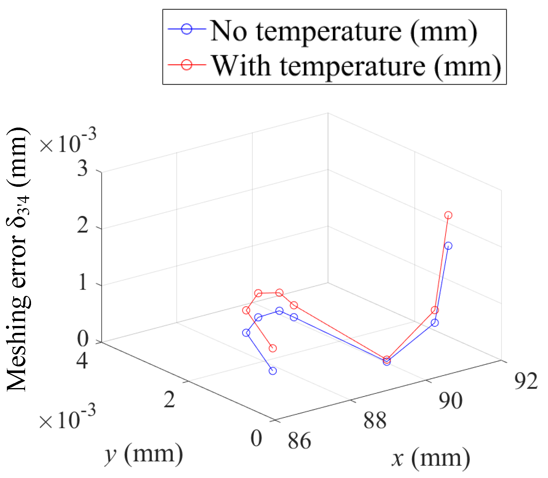
| No Temperature | With Temperature | ||||
|---|---|---|---|---|---|
| Before Deformation (mm) | After Deformation (mm) | Radius Difference (mm) | Before Deformation (mm) | After Deformation (mm) | Radius Difference (mm) |
| 87.50001 | 87.50137 | 0.001361 | 87.49996 | 87.50254 | 0.002589 |
| 87.96042 | 87.9628 | 0.002373 | 87.96038 | 87.96388 | 0.003504 |
| 88.41834 | 88.42083 | 0.002494 | 88.41836 | 88.42268 | 0.004324 |
| 88.87398 | 88.87638 | 0.002402 | 88.87395 | 88.87846 | 0.004508 |
| 89.32725 | 89.32971 | 0.002463 | 89.32725 | 89.33252 | 0.005268 |
| 89.77824 | 89.77896 | 0.000716 | 89.77831 | 89.7825 | 0.004185 |
| 90.22696 | 90.22597 | −0.00099 | 90.227 | 90.23014 | 0.003144 |
| 90.67344 | 90.67352 | 7.72 | 90.67351 | 90.67691 | 0.003402 |
| 91.11783 | 91.11916 | 0.001337 | 91.11783 | 91.12363 | 0.005799 |
| 91.56003 | 91.56075 | 0.000724 | 91.56 | 91.56513 | 0.005124 |
| 92.00001 | 92.0012 | 0.001194 | 92.00003 | 92.00616 | 0.006127 |
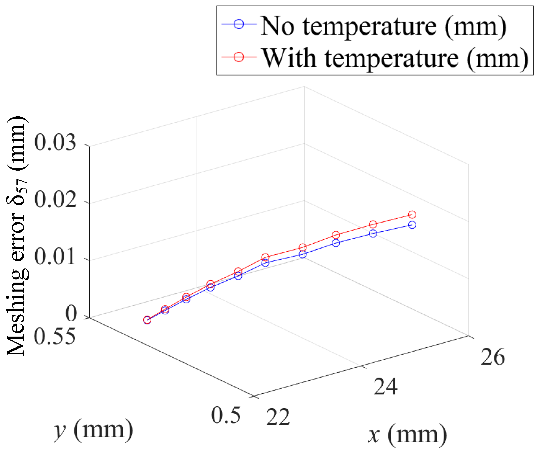
| No Temperature | With Temperature | ||||
|---|---|---|---|---|---|
| Before Deformation (mm) | After Deformation (mm) | Radius Difference (mm) | Before Deformation (mm) | After Deformation (mm) | Radius Difference (mm) |
| 23.8238 | 23.90013 | 0.076329 | 24.2386 | 24.33186 | 0.093254 |
| 24.23868 | 24.30746 | 0.06878 | 24.64855 | 24.72476 | 0.076204 |
| 24.64866 | 24.69927 | 0.050611 | 25.0533 | 25.11462 | 0.061315 |
| 25.05332 | 25.08933 | 0.036009 | 25.45233 | 25.49516 | 0.042833 |
| 25.45229 | 25.46973 | 0.017433 | 25.8455 | 25.86815 | 0.022646 |
| 25.84553 | 25.84219 | −0.00334 | 26.23244 | 26.23121 | −0.00123 |
| 26.23242 | 26.20512 | −0.02729 | 26.61312 | 26.5875 | −0.02562 |
| 26.61316 | 26.56096 | −0.0522 | 26.98747 | 26.93468 | −0.05279 |
| Gears | Module (mm) | Number of Teeth | Width (mm) | Pressure Angle (°) |
|---|---|---|---|---|
| Pinion | 3 | 14 | 36 | 20 |
| Gear | 3 | 44 | 30 | 20 |
| Gears | Tooth Profile Tolerance (m) | Tooth Profile form Error (m) | Tooth Profile Slope Deviation (m) | Tooth Line Tolerance (m) |
|---|---|---|---|---|
| Pinion | 20 | 19 | 15 | 18 |
| Gear | 25 | 19 | 15 | 18 |
| Parameters | Ideal Pinion | Error Pinion | Multiple | Ideal Gear | Error Gear | Multiple |
|---|---|---|---|---|---|---|
| CPRESS/MPa | 203 | 1039 | 5.12 | 226.4 | 1130 | 4.99 |
Disclaimer/Publisher’s Note: The statements, opinions and data contained in all publications are solely those of the individual author(s) and contributor(s) and not of MDPI and/or the editor(s). MDPI and/or the editor(s) disclaim responsibility for any injury to people or property resulting from any ideas, methods, instructions or products referred to in the content. |
© 2024 by the authors. Licensee MDPI, Basel, Switzerland. This article is an open access article distributed under the terms and conditions of the Creative Commons Attribution (CC BY) license (https://creativecommons.org/licenses/by/4.0/).
Share and Cite
Zhang, M.; Zhang, Z.; Xiong, J.; Chen, X. Accuracy Analysis of Complex Transmission System with Distributed Tooth Profile Errors. Machines 2024, 12, 459. https://doi.org/10.3390/machines12070459
Zhang M, Zhang Z, Xiong J, Chen X. Accuracy Analysis of Complex Transmission System with Distributed Tooth Profile Errors. Machines. 2024; 12(7):459. https://doi.org/10.3390/machines12070459
Chicago/Turabian StyleZhang, Min, Zhijing Zhang, Jian Xiong, and Xiao Chen. 2024. "Accuracy Analysis of Complex Transmission System with Distributed Tooth Profile Errors" Machines 12, no. 7: 459. https://doi.org/10.3390/machines12070459