1. Introduction
The rapid development of robots in recent years is reflected by technological advances and the miniaturization of electronic components. These machines are now taking on more complex forms, from the large stationary machines of a few years ago to the small, fast-moving robots that are seen today. Their task varies according to their specifications and the environment in which they operate, for example:
These may include Autonomous Underwater Vehicles (AUVs) [
1,
2], where the robot can be used to monitor liquid-based industrial processes,
They may evolve in a forestry environment, as per the work proposed in [
3], where the robot collects biomass samples and provides a dataset of different forest environments,
They may also be aerial, such as the work proposed in [
4], which uses an unmanned aerial vehicle (UAV) for cellular network relay inspection.
The crucial element that enables them to accomplish their task, and which is needed in all modern mobile robots, is the ability to secure their own energy source or storage unit. Typically, a battery is the only element that is added for these devices, sometimes coupled with solar panels to provide greater flexibility of use and increased autonomy. Energy storage is one of the most critical aspects to consider when designing a robot, especially with the miniaturization of robots and the diversification of their activity; many different types of batteries can be applied in the field of robotics [
5]. The most widely used battery systems in robotics today are based on electrochemical batteries, particularly lithium-ion technologies, and is mainly due to their high energy density, power density and their great efficiency. Additionally, traditional batteries such as nickel or lead batteries contain toxic and harmful metals and resources that are found in politically unstable regions [
6]. One conventional lithium-ion cell is composed of electrode pairs making up the cell, called the anode and cathode, which are usually isolated by a "separator" that prevents physical contact to be made between them. As with all rechargeable batteries, Lithium–polymer (Li–po) batteries make use of the red-ox phenomenon that occurs in their electrode. This type of reaction involves the transfer of electrons from one material to another through an external electrical circuit.
The management of the required energy for the proper functioning of these robots is a crucial aspect that must be carried out with the utmost rigor. It is mainly achieved using a so-called battery management system and fragmenting the performance of the battery into different states, namely the state of charge (SOC) which represents the ratio between the stored energy in
at a specific time “
t” and the maximal energy that can be stored in the battery also in
in a reference time “
” and the state of health (SOH) which represents the total amount of energy that can be stored in the battery in a specific time period where 1 means that the cell is totally healthy, and 0 that it is totally damaged. In general, a battery is considered to be at the end of its life when it reaches an SOH value of 0.6 [
7]. The BMS is an embedded system device based on electronic components that continuously monitors various parameters. The primary function of a BMS, besides determining the SOC and SOH, is to protect the battery(ies) from over-voltage and high current draw, and to prevent the battery(ies) from reaching a high temperature [
8,
9].
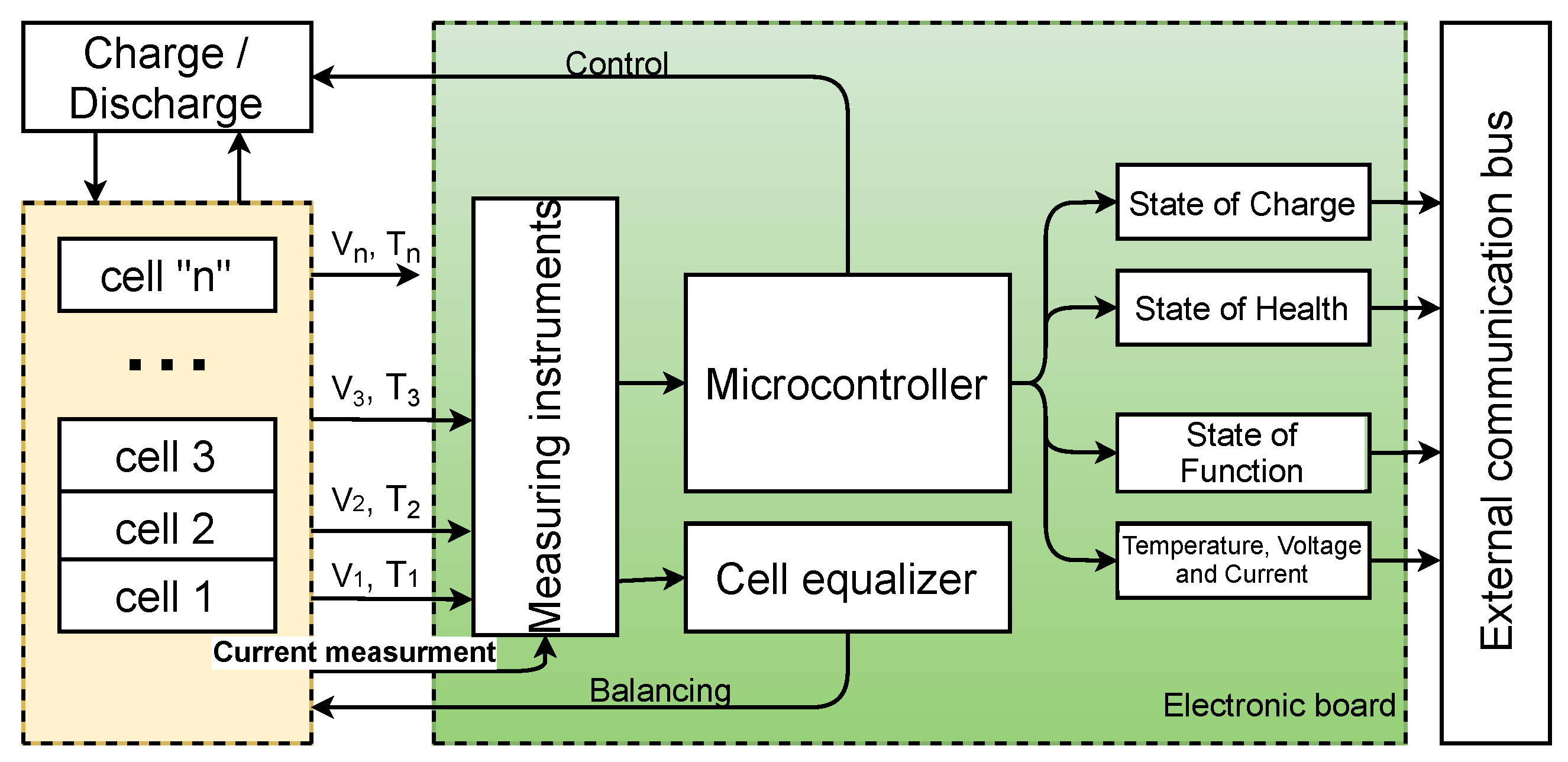
Figure 1 shows a graphic representation for a series configuration battery management system.
The principle that links the different components of the BMS is as follows. They are composed of a central microcontroller that gathers the current, voltage and temperature measurements for each cell independently through measuring instruments, then calculates, by a specific method, the different states of the battery (SOC, SOH and state of function (SOF)) that will be sent directly to the robot (by Wi-Fi, Bluetooth, or wiring). The microcontroller can control the charging and discharging behavior as well as limit the current flowing through the cells. A BMS must also be equipped with a cell equalizer and battery protection to allow SOC balancing between the cells and to guarantee safe use of the device. However, the development of battery energy management strategies has not followed the same path and has not attracted the same interest from researchers as the development of batteries or robots. This has led to the use of basic methods, such as Open Circuit Voltage (OCV) and Coulomb Counting (CC) in engineering applications (smartphones, laptops, drones, robots) thus far. For example, the
MarXbot [
10], a miniature mobile robot whose operation is based on a collective swarm of robots working in symbiosis and evolving at the same time for a specific task, was designed with a focus on energy management and autonomy. The robot can replace its own battery during operation and offers energy optimization by disabling unnecessary modules; however, it only uses the CC method to perform battery monitoring. In addition, in some battery-based systems [
11,
12], battery management is left to an external commercial component that is directly connected to the main system and provides it with essential information. These products can be applied in different systems, from the smallest to the biggest, and they vary in complexity and especially in price, e.g.,
RDDRONE-BMS772, which is a standalone BMS reference design suitable for mobile robotics such as drones and rovers, supporting 3- to 6-cell batteries. It has typical temperature, over-current and over-voltage protections features for the battery, and the SOC is computed through a CC method [
13], or the
PH3059HD26, which is a smart battery. It comprises 8 × 3.6 V 2.6 Ah 18,650 cells in an 8-series configuration and can deliver up to 12 A, the internal BMS integrated with the battery use an impedance tracking fuel gauge [
14], suggesting the application of a simple resistor equivalent model and an open circuit voltage technique for SOC prediction. This loss of interest has resulted in the limitation of use for more complex methods only in a laboratory-based environment, operating using computers via software such as MATLAB.
The number of scientific publications dealing with methods such as the Kalman Filter (KF) [
15], the Extended Kalman Filter (EKF) [
16,
17,
18], the Ascending Extended Kalman Filter (AEKF) [
19], Sliding Mode [
20] and Artificial Intelligence (AI) [
21] has been increasing in recent years. However, the constraint of computational power limitation is not really addressed in most scientific papers dealing with this topic. This observation has already been tackled in a previous work by the authors [
22], which focused on validating the possibility of the implementation of an EKF in an 8-bit microcontroller, working autonomously and performing SOC approximation on the fly and in [
23] where the Dual Coulomb Counting Extended Kalman Filter approach (DCC-EKF) is described. Furthermore, to the authors’ knowledge, all research done so far in the area of battery energy management using algorithms such as EKF is based on laboratory experiments with software such as MATLAB. This paper focuses on describing a compliant, lightweight battery management system based on ATMEGA328P microcontrollers, capable of monitoring and operating a wide variety of lithium batteries, with a prior update of the OCV(SOC) relationship, in a wide variety of applications, and using the DCC-EKF approach for SOC prediction and monitoring. The developed card has an energy efficiency of 94% and calculates the SOC with a maximum error of 5% for an estimated design cost of EUR 32.
Taking this introduction into account, the document is divided into six sections. The second section provides a brief description of the DCC-EKF approach. The third section presents the developed prototype, highlighting the main components as well as the relationships between them. The fourth section presents the results, both for the performance of the DCC-EKF approach compared to an EKF algorithm, and the energy efficiency of the prototype. The fifth section offers a brief discussion, and finally ends with a conclusion and future work.
2. Dual Coulomb Counting Extended Kalman Filter Approach
Linear systems are the mathematical representation of a linear differential equation. The KF algorithm takes this mathematical formula of the model, and adds the uncertainty of the process and measurements. This noise is generally represented in the literature by
and
, which predicts the SOC by passing through prediction and correction steps. However, if this model is unable to describe the behavior of nonlinear systems, the EKF is then applied, which is based on a first-order linearization using the Jacobian matrices of the system. For the EKF to accurately track the SOC of each cell independently, it is initially essential to define the covariance matrix P, the process noise matrix Q, and the measurement noise matrix R. These initializations are summarized in
Table 1. Then, it is necessary to identify the equivalent electrical parameters for each cell (
,
and
for the first-order equivalent model). To determine these battery parameters, a pulsed constant current discharge is typically applied to the cell and then, using a least-squares curve-fitting method, these parameters along with the OCV-SOC relationship can be extracted. The EKF having been discussed in previous articles, it is not necessary to go into this subject in depth, so we refer the reader to reference [
22].
Indeed, using an EKF alone in the battery domain is unthinkable, as the equivalent parameters evolve over time. It is, therefore, necessary to update them after a certain period of time, otherwise the EKF can fail in its prediction. This aspect is further discussed in the discussion section. Therefore, it is essential to link it with another algorithm. For this purpose, two main types of methodology are applied for parameter prediction: the so-called offline method, which extracts the parameters following a constant current discharge test of a few seconds, then followed by a rest period for the cell, and the so-called online methods, which allow an on-the-fly estimation, by applying algorithms such as the Dual Extended Kalman Filter (DEKF) [
24] or an online parameter estimator [
25]. Unfortunately, the application of an online technique will further increase the sampling time, resulting in a parameter prediction divergence and a decrease in accuracy for the implemented EKF. However, in the case of offline techniques, it is quite possible, but after a certain period of operation of the cells, users will have to perform this tedious test and will lose the flexibility aspect intended for this product. Algorithm 1 summarizes the algorithm implemented in the master microcontroller, while Algorithm 2 summarizes the algorithm implemented in each slave microcontroller, for a more in-depth explanation of each EKF and CC function, it is advisable to read the authors’ previous work [
23].
| Algorithm 1: Master microcontroller algorithm |
![Machines 09 00313 i001]() |
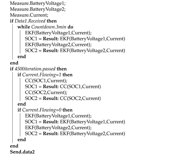
| Algorithm 2: Slave microcontroller algorithm |
![Machines 09 00313 i002]() |
The master microcontroller, first by , provides initialization parameters to the other slave microcontrollers. The initialization data are user definable and can influence the accuracy by introducing the battery capacity and the initial SOC. Then, in the second part, it imports the predicted state of charge and other data from each slave microcontroller, checks if it has reached or exceeded the limits, and allows or not the charging/discharging of the cells. It finally ends by displaying the data.
The slave microcontroller collects the current and voltage measurements and remains in standby until the master microcontroller sends the initialization parameters. As soon as they are received, the microcontrollers start predicting the SOC () for each cell independently by calling the EKF function implemented in the algorithm. After 4500 iterations (equivalent to 3 min) two choices are offered to the microcontroller depending on the current condition:
For a non-null current, the slave microcontroller uses the CC function to monitor the SOC,
For a null current, it uses the EKF function to update the SOC value.
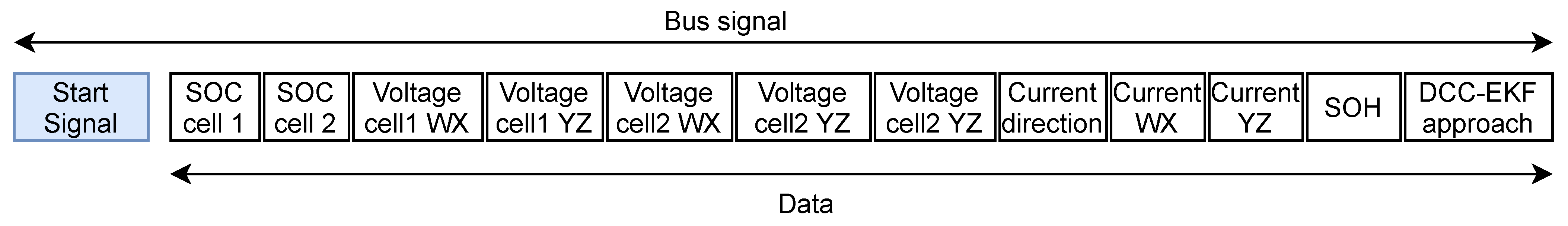
The slave microcontrollers continuously send data () to the master microcontroller.
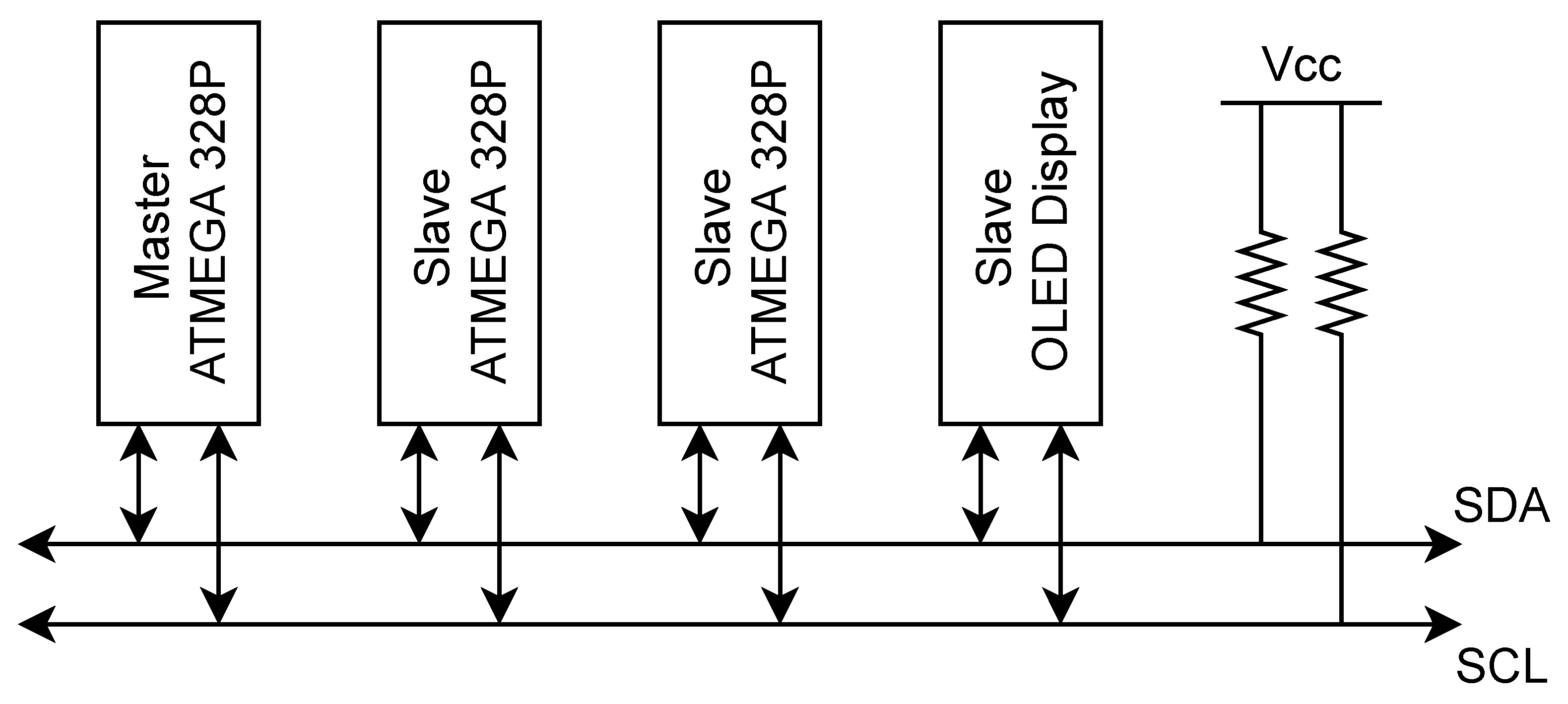
Kalman filtering consists of performing operations on matrices and vectors, from the simple addition and multiplication of two vectors to the inversion of a matrix, in this type of operation, the algorithm must be expressed by mathematical relationships equivalent to each operation. Moreover, the computational complexity of these filters grows extremely fast with the size of the system model, which limits their use in real-time applications. One solution to bridge the gap between the limited computational capabilities and the requirements needed for accurate SOC estimation is to consider dividing the system into multiple subsystems, where each subsystem performs a specific task while maintaining continuous communication. Thus, the master/slave architecture seeks to maintain low sampling time and low CPU usage. The overall algorithm is implemented in three ATMEGA328P microcontrollers, where one slave microcontroller is assigned to monitor two batteries, thus reducing overall complexity. In addition to adopting a basic equivalent battery model, using this architecture offers a processing time of 0.04 seconds with the recommended microcontroller frequency of 16 MHz, the memory used reaches about 28% for each slave microcontroller and 84% for the master microcontroller. The EKF, by continuously switching between the prediction and correction steps, can determine the SOC in 4500 iterations, the function is based on using the current and voltage measurements as input to the system; as the sampling time of this function is set to 0.04, it therefore takes 3 min to converge to a correct value. Algorithm 3 summarizes the EKF function, where
is the state vector,
is the system matrix,
is the system’s output,
is the system’s input,
is the input matrix,
is the output matrix and
is the sampling time.
| Algorithm 3: Extended Kalman Filter Function |
![Machines 09 00313 i003]() |
5. Discussion
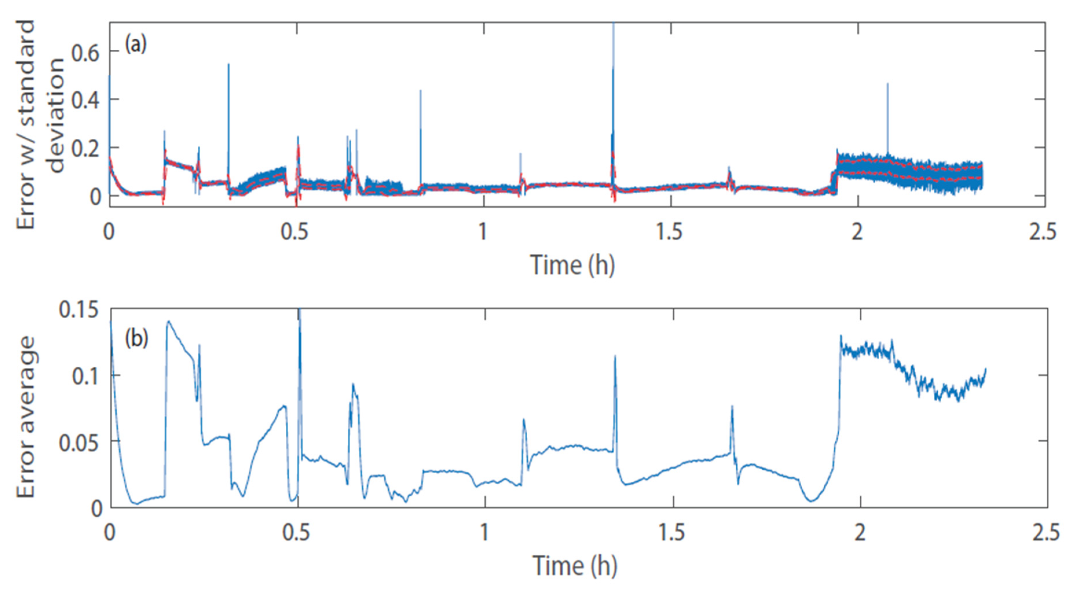
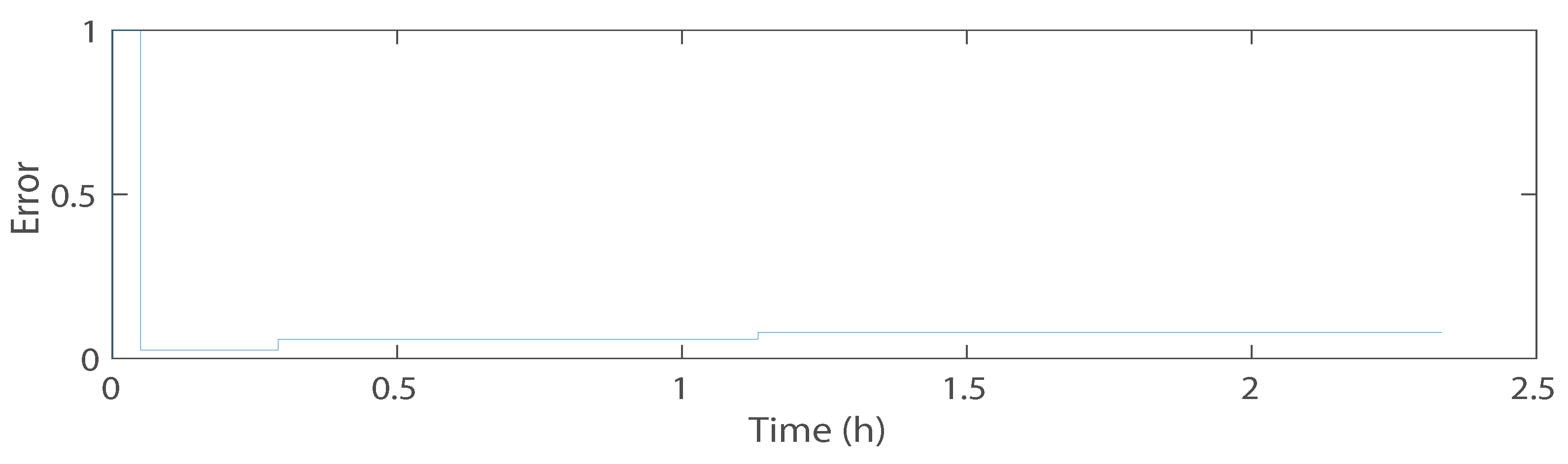
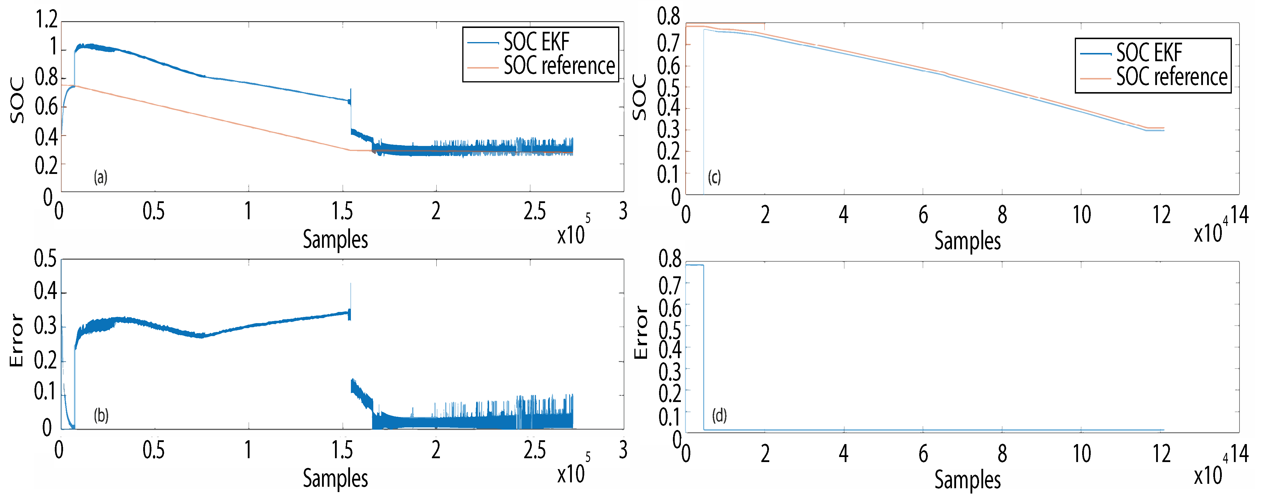
Although a Kalman filtering technique is reported in the literature as a SOC prediction tool, using software such as MATLAB, its behavior with an incorrect parameterization of the equivalent battery model is not widely reported in the literature in this field. The proposed DCC-EKF approach takes advantage of the EKF’s ability to predict quickly and accurately the SOC when the cell is at rest, or for a low flowing current, it reaches an maximum error in accuracy of about 5% for accurate initialization of the battery capacity and erroneous initialization of the SOC, even with a low current flowing through the cells and an inaccurate setting of the first-order battery parameters (
,
and
), unlike the OCV, which requires a fully rested battery and 1 h to obtain an accurate result. In this paper, accuracy is defined as the difference between
and (
) for an average of 100 samples after result convergence:
From
Figure 11 it can be concluded that for practical purposes, the EKF should never be used alone, and should either be coupled with another algorithm, or require a regular update of the cell parameters, as they evolve over time. Nevertheless, the EKF function represents an asset that can be used to its advantage. It allows the user to take advantage of its excellent behavior when the batteries are at rest, as the filter converges directly after a few minutes for a prediction error of less than 5% for an SOC between 80% and 35%, and then the CC method is used, which allows the SOC to be accurately monitored and kept stable throughout the discharge process. This method replaces the CC-OCV method that is usually applied in commercial products and offers an increased prediction accuracy. Whether the parameters are correct or not, the SOC is accurately predicted in record time, even with noisy measurements, which is the main advantage of this hybrid CC algorithm.
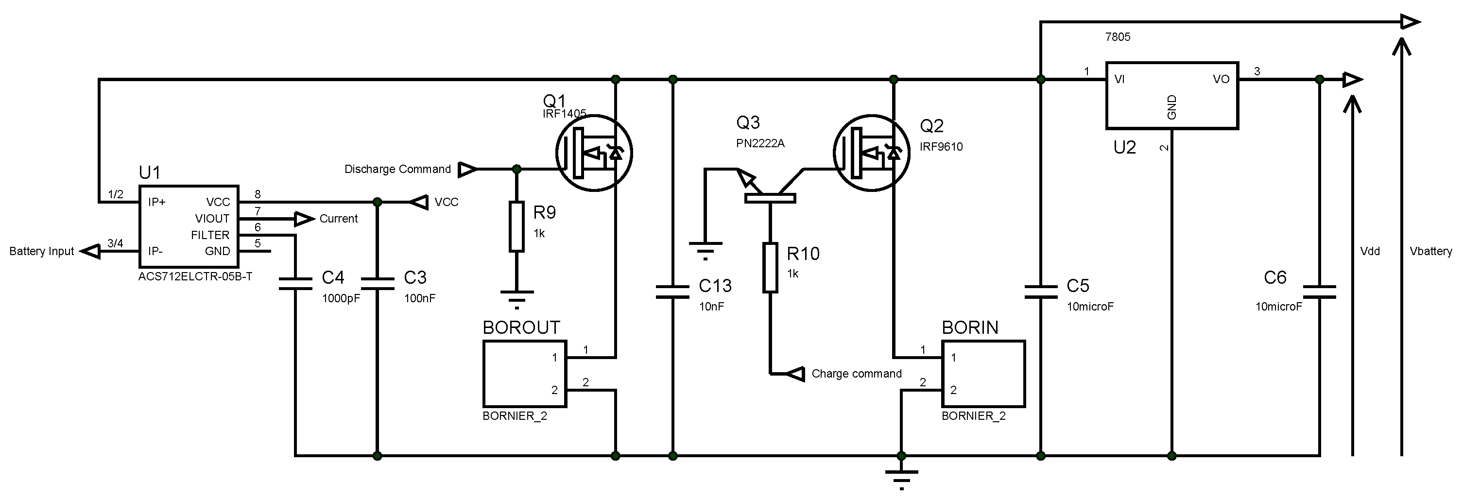
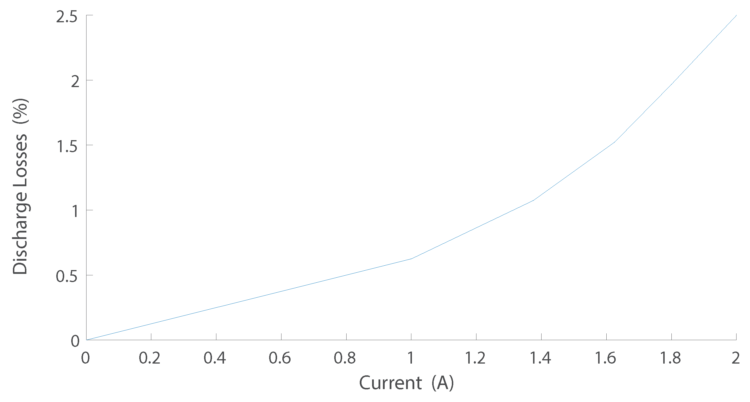
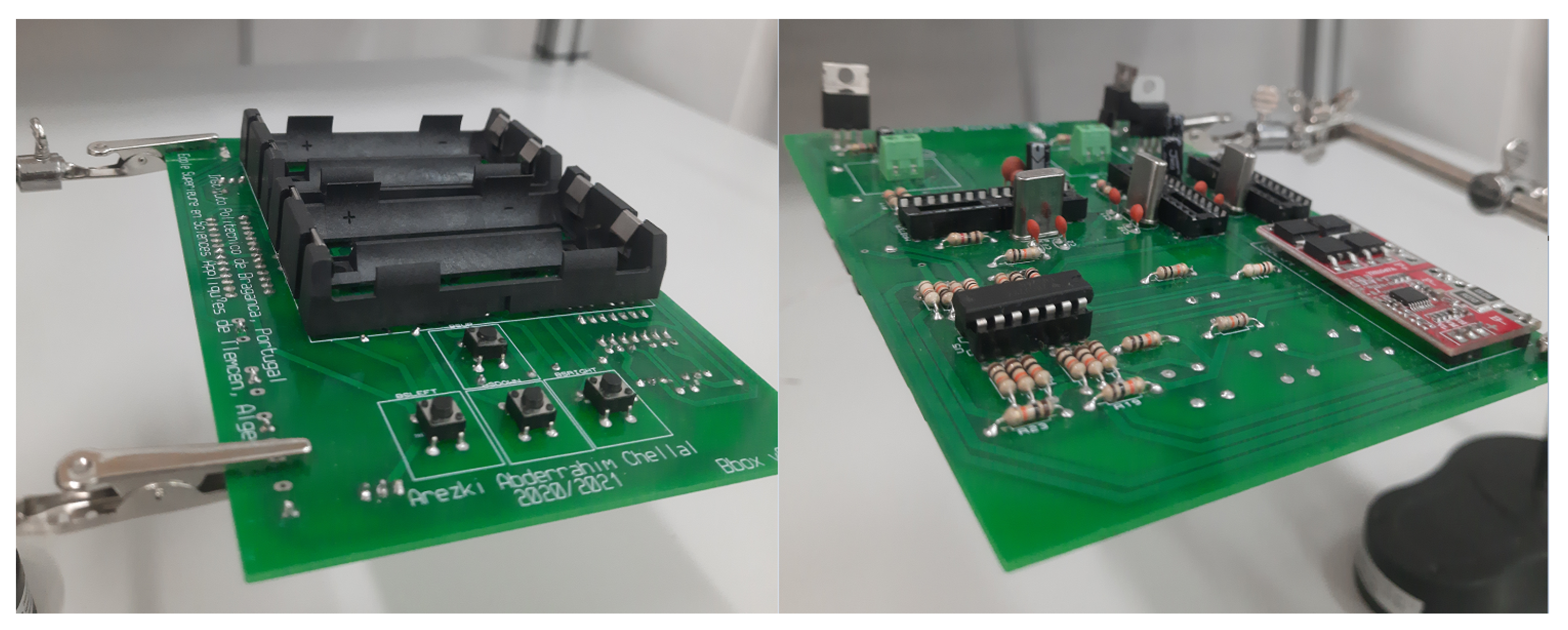
The overall product efficiency is defined as the average efficiency between the component consumption efficiency, the charging process efficiency and discharging process efficiency, which is 96.15%, 90.38% and 93.60%, respectively. The discharge process efficiency was calculated considering the maximum value (2.5%) with the component consumption. The overall efficiency of the prototype is therefore 94.38%. The developed printed circuit board (PCB), shown in
Figure 14, can be placed and connected to the overall system. This prototype can also be connected to small solar-powered systems, either with robots or other systems.
6. Conclusions and Future Work
The aspect of energy management has always been an important aspect in electrical and energetic systems. In mobile systems, whether they are large systems such as hybrid vehicles or small systems such as mobile robots and smartphones, the battery is the only source of energy on which they can rely. It is, therefore, very important to optimize the use of this stored energy, which can be done by knowing the precise state of charge of each cell in the battery pack. The developed board has several functions, to monitor the batteries, manage the charging and discharging cycle, and to increase its life-span. It relies on accurate measurement of the current and voltage only, even in a noisy environment. The proposed architecture can offer an initializable black box solution, which is easy to integrate into any battery-powered device, thanks to its small size of 149 mm × 100 mm, a relatively good accuracy, compared to already marketed products of about 5% on average, and low cost, which is estimated through the components purchase cost and PCB manufacturing of EUR 32.
The DCC-EKF approach represents only one way to improve the online SOC prediction and monitoring task. Regarding future work, enabling SOC monitoring and prediction by the full EKF should be considered. To this end, validation of the implementation of different approaches to determine and update the online equivalent battery parameters using different methods proposed in the literature should be planned—mainly the double extended Kalman filter using 8-bit microcontrollers or more. The ESP32 is a very good candidate that is already being considered for use in future releases. Additionally, product minimization is an aspect that is defined as essential according to the aspiration of the product specification. The screen interaction of the product is easy for the user, but consumes power and is space consuming, added to this the push buttons. It will therefore be eliminated in favor of other modes of communication.


 ,
, 


