Article

Design of an Embedded Energy Management System for Li–Po Batteries Based on a DCC-EKF Approach for Use in Mobile Robots

1
Research Centre of Digitalization and Intelligent Robotics CeDRI, Instituto Politécnico de Bragança, 5300-252 Bragança, Portugal
2
Robotics and Intelligent Systems Research Group, INESC TEC, 4200-465 Porto, Portugal
3
Faculty of Engineering, University of Porto, 4200-465 Porto, Portugal
4
Telecommunication Laboratory of Tlemcen LTT, University of Abou Bakr Belkaid, Tlemcen 13000, Algeria
5
Higher School of Applied Sciences, Tlemcen 13000, Algeria
*
Author to whom correspondence should be addressed.
Machines 2021, 9(12), 313; https://doi.org/10.3390/machines9120313
Submission received: 1 October 2021 / Revised: 23 November 2021 / Accepted: 23 November 2021 / Published: 25 November 2021
(This article belongs to the Special Issue Modeling, Sensor Fusion and Control Techniques in Applied Robotics)

Abstract

:
In mobile robotics, since no requirements have been defined regarding accuracy for Battery Management Systems (BMS), standard approaches such as Open Circuit Voltage (OCV) and Coulomb Counting (CC) are usually applied, mostly due to the fact that employing more complicated estimation algorithms requires higher computing power; thus, the most advanced BMS algorithms reported in the literature are developed and verified by laboratory experiments using PC-based software. The objective of this paper is to describe the design of an autonomous and versatile embedded system based on an 8-bit microcontroller, where a Dual Coulomb Counting Extended Kalman Filter (DCC-EKF) algorithm for State of Charge (SOC) estimation is implemented; the developed prototype meets most of the constraints for BMSs reported in the literature, with an energy efficiency of 94% and an error of SOC accuracy that varies between 2% and 8% based on low-cost components.

1. Introduction

The rapid development of robots in recent years is reflected by technological advances and the miniaturization of electronic components. These machines are now taking on more complex forms, from the large stationary machines of a few years ago to the small, fast-moving robots that are seen today. Their task varies according to their specifications and the environment in which they operate, for example:
  • These may include Autonomous Underwater Vehicles (AUVs) [1,2], where the robot can be used to monitor liquid-based industrial processes,
  • They may evolve in a forestry environment, as per the work proposed in [3], where the robot collects biomass samples and provides a dataset of different forest environments,
  • They may also be aerial, such as the work proposed in [4], which uses an unmanned aerial vehicle (UAV) for cellular network relay inspection.
The crucial element that enables them to accomplish their task, and which is needed in all modern mobile robots, is the ability to secure their own energy source or storage unit. Typically, a battery is the only element that is added for these devices, sometimes coupled with solar panels to provide greater flexibility of use and increased autonomy. Energy storage is one of the most critical aspects to consider when designing a robot, especially with the miniaturization of robots and the diversification of their activity; many different types of batteries can be applied in the field of robotics [5]. The most widely used battery systems in robotics today are based on electrochemical batteries, particularly lithium-ion technologies, and is mainly due to their high energy density, power density and their great efficiency. Additionally, traditional batteries such as nickel or lead batteries contain toxic and harmful metals and resources that are found in politically unstable regions [6]. One conventional lithium-ion cell is composed of electrode pairs making up the cell, called the anode and cathode, which are usually isolated by a "separator" that prevents physical contact to be made between them. As with all rechargeable batteries, Lithium–polymer (Li–po) batteries make use of the red-ox phenomenon that occurs in their electrode. This type of reaction involves the transfer of electrons from one material to another through an external electrical circuit.
The management of the required energy for the proper functioning of these robots is a crucial aspect that must be carried out with the utmost rigor. It is mainly achieved using a so-called battery management system and fragmenting the performance of the battery into different states, namely the state of charge (SOC) which represents the ratio between the stored energy in A m p e r e h o u r ( A h ) at a specific time “t” and the maximal energy that can be stored in the battery also in ( A h ) in a reference time “ t r e f ” and the state of health (SOH) which represents the total amount of energy that can be stored in the battery in a specific time period where 1 means that the cell is totally healthy, and 0 that it is totally damaged. In general, a battery is considered to be at the end of its life when it reaches an SOH value of 0.6 [7]. The BMS is an embedded system device based on electronic components that continuously monitors various parameters. The primary function of a BMS, besides determining the SOC and SOH, is to protect the battery(ies) from over-voltage and high current draw, and to prevent the battery(ies) from reaching a high temperature [8,9]. Figure 1 shows a graphic representation for a series configuration battery management system.
The principle that links the different components of the BMS is as follows. They are composed of a central microcontroller that gathers the current, voltage and temperature measurements for each cell independently through measuring instruments, then calculates, by a specific method, the different states of the battery (SOC, SOH and state of function (SOF)) that will be sent directly to the robot (by Wi-Fi, Bluetooth, or wiring). The microcontroller can control the charging and discharging behavior as well as limit the current flowing through the cells. A BMS must also be equipped with a cell equalizer and battery protection to allow SOC balancing between the cells and to guarantee safe use of the device. However, the development of battery energy management strategies has not followed the same path and has not attracted the same interest from researchers as the development of batteries or robots. This has led to the use of basic methods, such as Open Circuit Voltage (OCV) and Coulomb Counting (CC) in engineering applications (smartphones, laptops, drones, robots) thus far. For example, the MarXbot [10], a miniature mobile robot whose operation is based on a collective swarm of robots working in symbiosis and evolving at the same time for a specific task, was designed with a focus on energy management and autonomy. The robot can replace its own battery during operation and offers energy optimization by disabling unnecessary modules; however, it only uses the CC method to perform battery monitoring. In addition, in some battery-based systems [11,12], battery management is left to an external commercial component that is directly connected to the main system and provides it with essential information. These products can be applied in different systems, from the smallest to the biggest, and they vary in complexity and especially in price, e.g., RDDRONE-BMS772, which is a standalone BMS reference design suitable for mobile robotics such as drones and rovers, supporting 3- to 6-cell batteries. It has typical temperature, over-current and over-voltage protections features for the battery, and the SOC is computed through a CC method [13], or the PH3059HD26, which is a smart battery. It comprises 8 × 3.6 V 2.6 Ah 18,650 cells in an 8-series configuration and can deliver up to 12 A, the internal BMS integrated with the battery use an impedance tracking fuel gauge [14], suggesting the application of a simple resistor equivalent model and an open circuit voltage technique for SOC prediction. This loss of interest has resulted in the limitation of use for more complex methods only in a laboratory-based environment, operating using computers via software such as MATLAB.
The number of scientific publications dealing with methods such as the Kalman Filter (KF) [15], the Extended Kalman Filter (EKF) [16,17,18], the Ascending Extended Kalman Filter (AEKF) [19], Sliding Mode [20] and Artificial Intelligence (AI) [21] has been increasing in recent years. However, the constraint of computational power limitation is not really addressed in most scientific papers dealing with this topic. This observation has already been tackled in a previous work by the authors [22], which focused on validating the possibility of the implementation of an EKF in an 8-bit microcontroller, working autonomously and performing SOC approximation on the fly and in [23] where the Dual Coulomb Counting Extended Kalman Filter approach (DCC-EKF) is described. Furthermore, to the authors’ knowledge, all research done so far in the area of battery energy management using algorithms such as EKF is based on laboratory experiments with software such as MATLAB. This paper focuses on describing a compliant, lightweight battery management system based on ATMEGA328P microcontrollers, capable of monitoring and operating a wide variety of lithium batteries, with a prior update of the OCV(SOC) relationship, in a wide variety of applications, and using the DCC-EKF approach for SOC prediction and monitoring. The developed card has an energy efficiency of 94% and calculates the SOC with a maximum error of 5% for an estimated design cost of EUR 32.
Taking this introduction into account, the document is divided into six sections. The second section provides a brief description of the DCC-EKF approach. The third section presents the developed prototype, highlighting the main components as well as the relationships between them. The fourth section presents the results, both for the performance of the DCC-EKF approach compared to an EKF algorithm, and the energy efficiency of the prototype. The fifth section offers a brief discussion, and finally ends with a conclusion and future work.

2. Dual Coulomb Counting Extended Kalman Filter Approach

Linear systems are the mathematical representation of a linear differential equation. The KF algorithm takes this mathematical formula of the model, and adds the uncertainty of the process and measurements. This noise is generally represented in the literature by ω k  and  υ k , which predicts the SOC by passing through prediction and correction steps. However, if this model is unable to describe the behavior of nonlinear systems, the EKF is then applied, which is based on a first-order linearization using the Jacobian matrices of the system. For the EKF to accurately track the SOC of each cell independently, it is initially essential to define the covariance matrix P, the process noise matrix Q, and the measurement noise matrix R. These initializations are summarized in Table 1. Then, it is necessary to identify the equivalent electrical parameters for each cell ( R p , C p and R t for the first-order equivalent model). To determine these battery parameters, a pulsed constant current discharge is typically applied to the cell and then, using a least-squares curve-fitting method, these parameters along with the OCV-SOC relationship can be extracted. The EKF having been discussed in previous articles, it is not necessary to go into this subject in depth, so we refer the reader to reference [22].
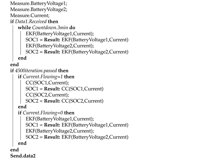
Indeed, using an EKF alone in the battery domain is unthinkable, as the equivalent parameters evolve over time. It is, therefore, necessary to update them after a certain period of time, otherwise the EKF can fail in its prediction. This aspect is further discussed in the discussion section. Therefore, it is essential to link it with another algorithm. For this purpose, two main types of methodology are applied for parameter prediction: the so-called offline method, which extracts the parameters following a constant current discharge test of a few seconds, then followed by a rest period for the cell, and the so-called online methods, which allow an on-the-fly estimation, by applying algorithms such as the Dual Extended Kalman Filter (DEKF) [24] or an online parameter estimator [25]. Unfortunately, the application of an online technique will further increase the sampling time, resulting in a parameter prediction divergence and a decrease in accuracy for the implemented EKF. However, in the case of offline techniques, it is quite possible, but after a certain period of operation of the cells, users will have to perform this tedious test and will lose the flexibility aspect intended for this product. Algorithm 1 summarizes the algorithm implemented in the master microcontroller, while Algorithm 2 summarizes the algorithm implemented in each slave microcontroller, for a more in-depth explanation of each EKF and CC function, it is advisable to read the authors’ previous work [23].
Algorithm 1: Master microcontroller algorithm
Machines 09 00313 i001
Algorithm 2: Slave microcontroller algorithm
Machines 09 00313 i002
The master microcontroller, first by S e n d . d a t a 1 , provides initialization parameters to the other slave microcontrollers. The initialization data are user definable and can influence the accuracy by introducing the battery capacity and the initial SOC. Then, in the second part, it imports the predicted state of charge and other data from each slave microcontroller, checks if it has reached or exceeded the limits, and allows or not the charging/discharging of the cells. It finally ends by displaying the data.
The slave microcontroller collects the current and voltage measurements and remains in standby until the master microcontroller sends the initialization parameters. As soon as they are received, the microcontrollers start predicting the SOC ( S O ^ C ) for each cell independently by calling the EKF function implemented in the algorithm. After 4500 iterations (equivalent to 3 min) two choices are offered to the microcontroller depending on the current condition:
  • For a non-null current, the slave microcontroller uses the CC function to monitor the SOC,
  • For a null current, it uses the EKF function to update the SOC value.
The slave microcontrollers continuously send data ( S e n d . d a t a 2 ) to the master microcontroller.
Kalman filtering consists of performing operations on matrices and vectors, from the simple addition and multiplication of two vectors to the inversion of a matrix, in this type of operation, the algorithm must be expressed by mathematical relationships equivalent to each operation. Moreover, the computational complexity of these filters grows extremely fast with the size of the system model, which limits their use in real-time applications. One solution to bridge the gap between the limited computational capabilities and the requirements needed for accurate SOC estimation is to consider dividing the system into multiple subsystems, where each subsystem performs a specific task while maintaining continuous communication. Thus, the master/slave architecture seeks to maintain low sampling time and low CPU usage. The overall algorithm is implemented in three ATMEGA328P microcontrollers, where one slave microcontroller is assigned to monitor two batteries, thus reducing overall complexity. In addition to adopting a basic equivalent battery model, using this architecture offers a processing time of 0.04 seconds with the recommended microcontroller frequency of 16 MHz, the memory used reaches about 28% for each slave microcontroller and 84% for the master microcontroller. The EKF, by continuously switching between the prediction and correction steps, can determine the SOC in 4500 iterations, the function is based on using the current and voltage measurements as input to the system; as the sampling time of this function is set to 0.04, it therefore takes 3 min to converge to a correct value. Algorithm 3 summarizes the EKF function, where x k R n × 1 is the state vector, A R n x n is the system matrix, y k p r e d R m × 1 is the system’s output, U i n r R m × 1 is the system’s input, B R n x m is the input matrix, C k R m × n is the output matrix and T s is the sampling time.
Algorithm 3: Extended Kalman Filter Function
Machines 09 00313 i003

3. Board Design

3.1. Components and Power Distribution

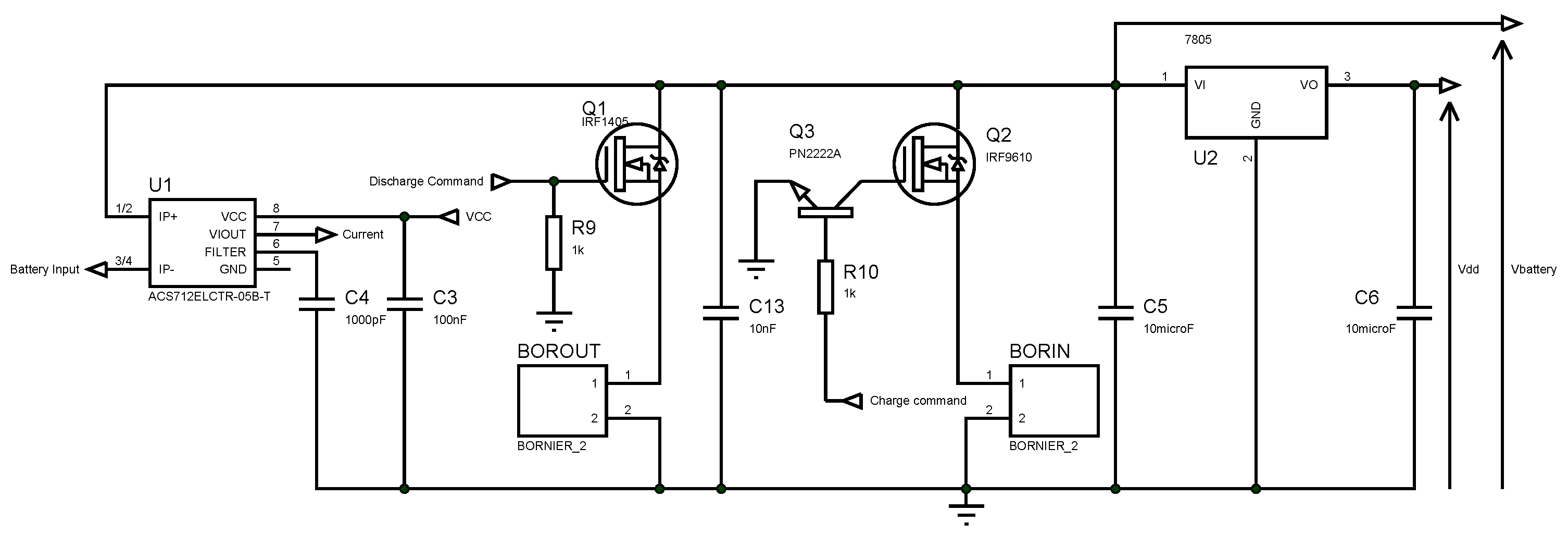
According to the established specifications and criteria reported in the literature, it is essential that the battery management system guarantees optimal operation of the cells with the possibility of electrically isolating it at any time, in order to increase its life and, therefore, that of the system in general. For this purpose, the designed electronic board has a separate output and input power. They are controlled by an N-channel mosfet IRF1405 and a P-channel mosfet IRF9610 respectively. These mosfets are directly controlled by the master microcontroller ATMEGA328P. It communicates with slave microcontrollers that calculate the SOC of each cell separately, based on the cell voltage measured by an operational amplifier and the circulating current measured by the ACS712 current sensor. In addition, the master microcontroller is connected to push buttons and an OLED display to allow easy navigation and communication with the users. Figure 2 shows the different relationships between the components of the electronic system.
The ATMEGA328P microcontroller choice is based on its characteristics: it meets the computing power needs, the small size, the power consumption, the availability of software and hardware development tools, the wide product availability, the reliability, and the documentation. It has some useful features as the Inter-Integrated Circuit (I2C), a fast Analog-to-Digital Conversion (ADC), a low power consumption and a relatively low price. To achieve autonomy, the necessary power needed to power up the electronic components is directly taken from the installed batteries. The voltage is stabilized and adjusted for BMS electronics by an LM7805 voltage regulator, which offers a voltage of 5 V at its output, and a maximum output current of 1 A [26]. All 78XX series regulators have a drop voltage of between 2 V and 3 V depending on the model. This implies an input voltage of at least 2 V to 3 V higher than the output voltage [27], therefore, this characteristic prohibits the use of this type of regulator in the design of an electronic circuit with one or two cells, since the minimum power supply offered by the battery is 3 V and 6 V, respectively. Three capacitors (C13, C5 and C6) are added to filter and limit the interference generated by the mosfets. The current entering and leaving the battery is measured using an ACS-712 current measuring device. Table 2 shows the sensor accuracy.
Since the device is intended to monitor 4 cells in series, the preference is to measure the voltage in each cell using an operational amplifier through a simple voltage divider. The LM324 quad operational amplifier was chosen for its availability and low cost. Figure 3 shows the wiring diagram of it on the batteries.
The power distribution and regulation is considered to be the most important constraint to address in embedded systems [28]. Figure 4 shows the electronic scheme for the power regulation, current measurement and energy control.
Three voltage levels are mainly present in the designed circuit, the first level is the input voltage, which is between 17 and 20 Volts ( V i n p u t ), the second voltage level is of the various electronic components and microcontrollers applied, which is 5 V ( V d d ), and finally, the last level is of the battery pack ( V b a t t e r y ), which has a variable value between 13.2 V and 17.2 V. The conversion from the V i n p u t to V b a t t e r y is achieved by the voltage drop between the drain and the source of the P-channel Mosfet IRF9610 ( V D S ) (Equation (1)).
V b a t t e r y = V i n p u t + V D S

3.2. Master and Slave Microcontrollers Communication

The battery states are determined for each cell independently of the others by a specific microcontroller assigned to it, and works with the principle of master/slave communication, with one microcontroller defined as a master to regroup the measurements and states gathered and computed from each slave microcontroller, analyze them and take the necessary precautions to avoid any deep charge or discharge of the batteries. Figure 5 shows the interconnection principal.
The communication between the microcontrollers is achieved via the I2C with master/slave communication, which takes the form of a successive signal bus. It is designated as data 1 in Figure 2 and is shown in Figure 6.
The bus signal begins with a start signal, equivalent to a value of 255. This start signal is implemented to ensure that the slave microcontroller receives the values in the correct order. It is followed by sending the battery capacity (C = WXYZ mAh) in two packets. Then, it sends the initial SOC value, the activation or deactivation of the DCC-EKF approach, as well as the battery protection, and finally obtains the initial SOH value.
The microcontrollers defined as slave perform the communication designated as data 2 in Figure 2. This communication is done during the on-mode. Figure 7 is a representation of the parameters continuously sent.
As in the case of communication in the reverse direction, a start signal is also used and has the same value of 255. This is followed by sending the calculated state of charge values for the first cell and the second cell in two different packets. Next, the voltage values are sent for each cell in two packets (packet 4, packet 5 and packet 6, packet 7), with the voltage taking the form of V = W.XY Z V. Then the direction of the current (charge or discharge) is sent, where current direction = 10 means discharge, and current direction = 254 means charge. Then the current value is sent in two packet (packet 9 and packet 10) with current = W.XY Z A. Finally in the last two packets the state of health value is sent, and the slave microcontroller confirms the use or not of the DCC-EKF approach.

4. Results

4.1. Performance Evaluation

To prove the feasibility of this approach, some tests will be performed using the results obtained from the same aged 3 Ah Lithium Nickel Manganese Cobalt Oxide (Li-NMC) battery with the reference INR18650. All tests were performed at room temperature and with an initial EKF and DCC-EKF estimator guess set at 50%. The reference SOC ( S O C r e f ) is computed following the CC technique with defined initial SOC value as mostly used in the literature [29,30]. The inital S O C r e f is derived from the OCV (SOC) relation. The first test consists of discharging the batteries with a changing current, and the current remains constant for a variable period of time and then changes, thus obtaining an environment similar to reality. A comparison between the results published in [22] and the DCC-EKF is to be shown in Figure 8. Both approaches are initialized with the correct parameters. The algorithms and different approaches described in the literature are rarely validated throughout the charging process, as the charging current in practical applications remains fairly constant during the entire process from the beginning to the end [31].
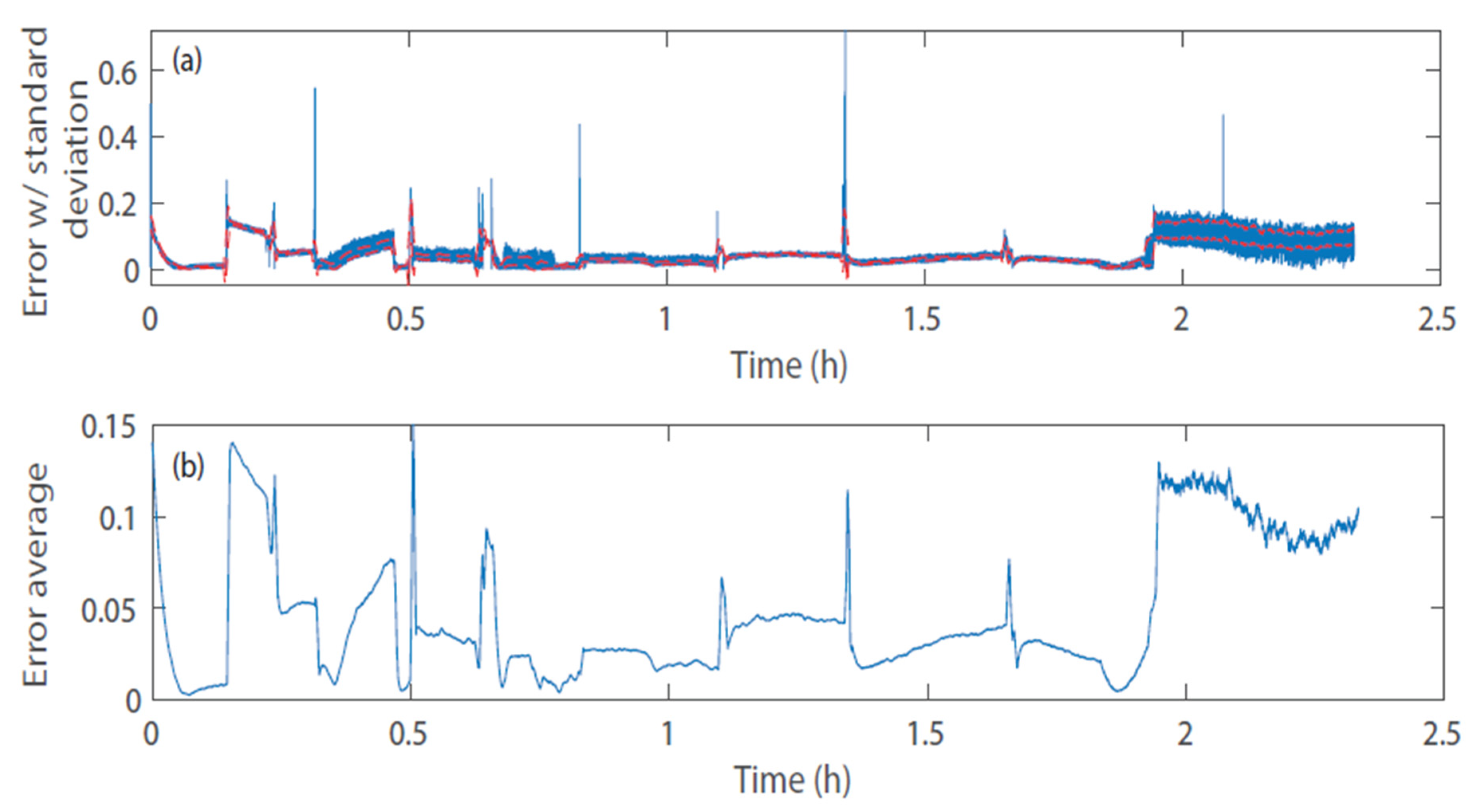
For the EKF algorithm, the estimated SOC follows the actual SOC value during all tests but more precisely between 80% and 34% of the battery SOC. Throughout the results and discussion in Figure 9, where the error, the standard deviation and the average error throughout the discharge test with the EKF method is shown, the high peaks will not be considered, as these peaks result from a noisy current measurement related to the abrupt current change from one level to another. This noise has been kept during this test to show the robustness of the EKF and the DCC-EKF approaches. However, it is necessary to highlight that the measurement noise for the prototype discussed in this article does not reach such high values, and is filtered.
From Figure 9, the variation of the standard deviation, as well as the mean value of the EKF error, can be clearly seen along the change of the SOC levels, and without a constant rate. A window of 500 samples was taken for the standard deviation and average calculation. For a SOC that varies between 100% and 80%, a fairly low standard deviation is found, in the order of 0.3% to 1% but compared to an error that is quite large. Indeed, it reaches a value of 14% and then gradually decreases until reaching a value of 5%, at approximately 80% SOC. Then, for a SOC ranging from 80% to 36%, a fairly low value, both for the standard deviation and the average error, is noted. In fact, it varies modestly between 0.4% and 0.27% throughout this SOC level, but still with an average error that varies between 1% and 4.6%. Finally, the values of an SOC below 36% are considerably large; in fact the standard deviation reaches a value of 2.9% with an average error of 11%. The overall average error is about 3.81% [22].
For the DCC-EKF algorithm, with the results shown in Figure 10, the SOC is predicted with an average error of 5%, and reaching a maximum error of 8%, this approach also gives a more linear and filtered result compared to EKF one.
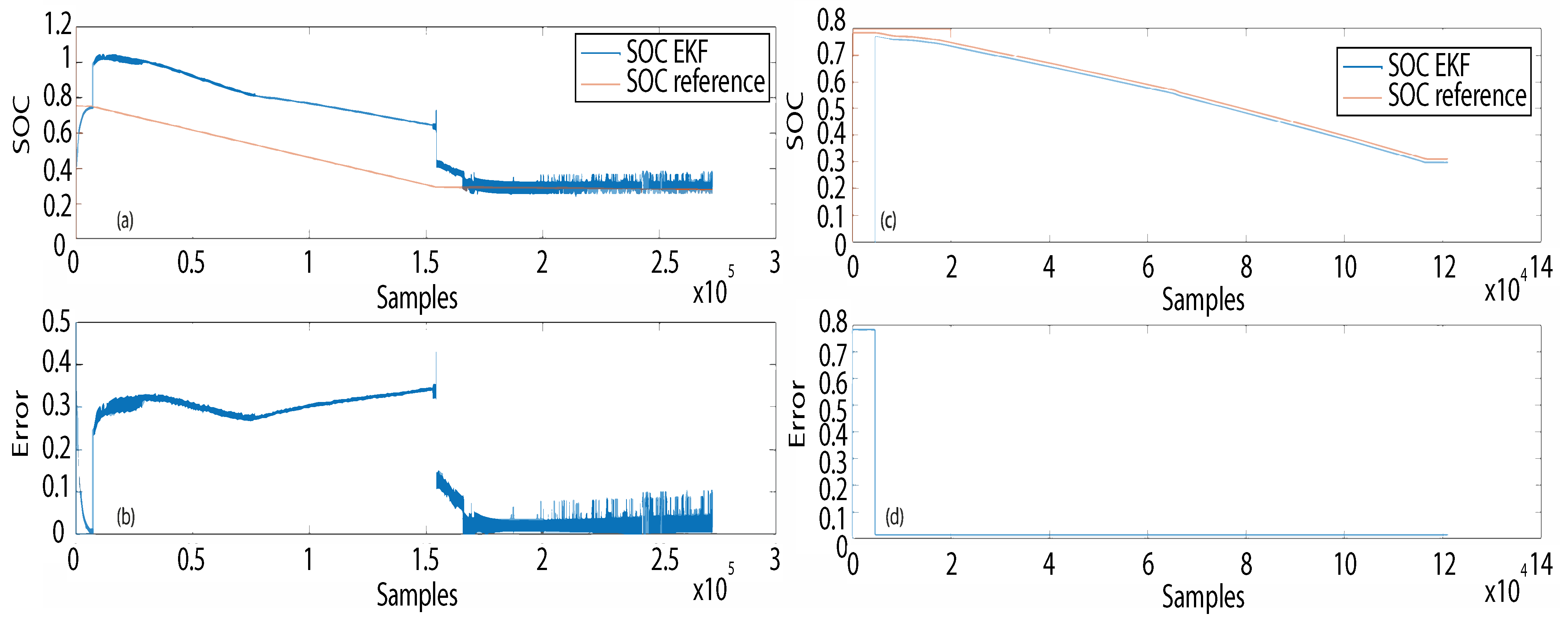
The second test consists of discharging the battery with a constant current, and a comparison will be made between the DCC-EKF approach and the EKF with wrong parameter initialization. The wrong initialization consists of deliberately modifying the parameters of the equivalent model described in article [22], thus a value of 0.2 Ω will be added for each resistance R t and R p and a value of 200 F for the C p , representing an average error of 40%, 50%, and 30% respectively. Figure 11 shows the results of the SOC prediction with a cell charged at 80%, discharged with a constant current for a defined period of time, then with no current flowing.
The EKF quickly predicted the SOC for the first samples, but as soon as the current started, an error of 30% was reached, and this was during the entire discharge period with a wrong parameter initialization. When the current stopped, the EKF converged rapidly, reaching a preliminary error of 10% within a few sampling times, and then slowly converged to the reference SOC. After about 3 min it reached an error of less than 5%. Although the error reached a value of 30% when the cell was in use, the EKF converged quickly for the battery at rest, with an error of 5%. This feature is applied in the DCC-EKF approach, where the prediction with the EKF is used while prohibiting the current flow for the first 4500 samples. This gives enough time for the EKF to converge to a correct value. As it can be seen, even with a bad characterization, the DCC-EKF approach allows good tracking of the SOC.
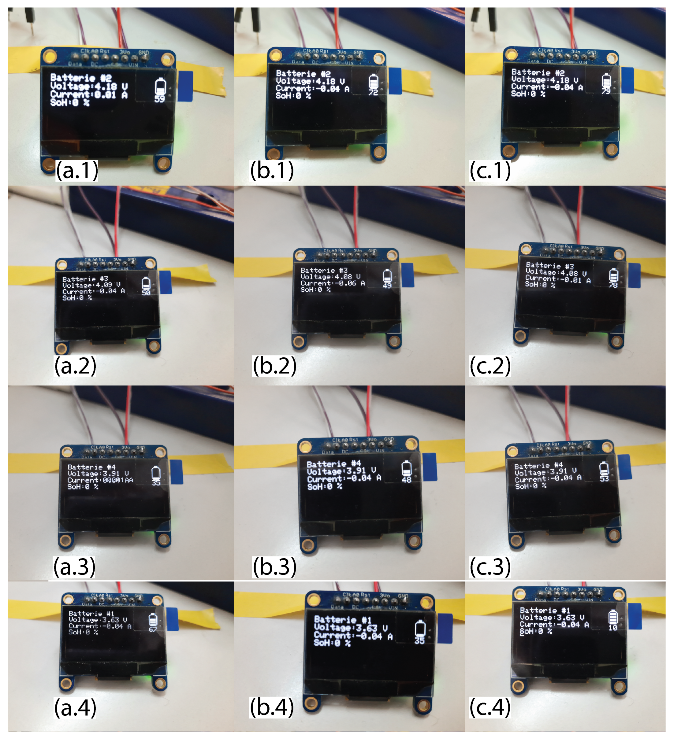
As shown in Figure 12, the SOC, voltage and current are directly displayed. In the normal operating area, the EKF prediction reaches an error of 5% in the worst case, for SOC cells above 80% the accuracy drops to 8%, while for SOC below 30% the algorithm diverges completely, confirming the graphics shown previously. For cell 2 (a.1, b.1 and c.1), the estimate has reached the SOC value with an error of 1.75%. For cell 3 (a.2, b.2 and c.2), after 1 min, the prediction has not yet reached the estimated value with an error of 6.90%. For cell 4 (a.3, b.3 and c.3), the estimate has reached the estimated value with an error of 2.02% and for cell 1 (a.4, b.4 and c.4), the algorithm diverges for the SOC estimate.

4.2. Prototype Efficiency

4.2.1. Components Energy Consumption

The energy consumption of the components is a determining factor as well as the most important of the constraints. It represents the consumption of the embedded systems components (microcontrollers, sensors, mosfets, etc.). The total consumption of this device is calculated by replacing the batteries with a power supply and measuring the voltage V b a t t e r y and the current I b a t t e r y supplied. The electronics consumes on average 1.15 W, giving it an efficiency of 96.15%. Taking a 4 × 2200 mAh cell as a reference, this device allows the battery to be monitored for a period of 88 h straight or the equivalent of 3 days and 16 h, after which the battery reaches 30% of its capacity and no further discharge will be allowed.

4.2.2. Charging Process Efficiency

When charging the battery, the current is set at a maximum value of 0.5 A, thus, the Mosfet IRF9610 causes a constant power loss of 0.52 W, with a power delivery of 8.60 W. Thus, the charging process has an efficiency of 94%. Taking into account both losses in the charging process and the components consumption, the total efficiency of the prototype reaches a value of 90.38%.

4.2.3. Discharging Process Efficiency

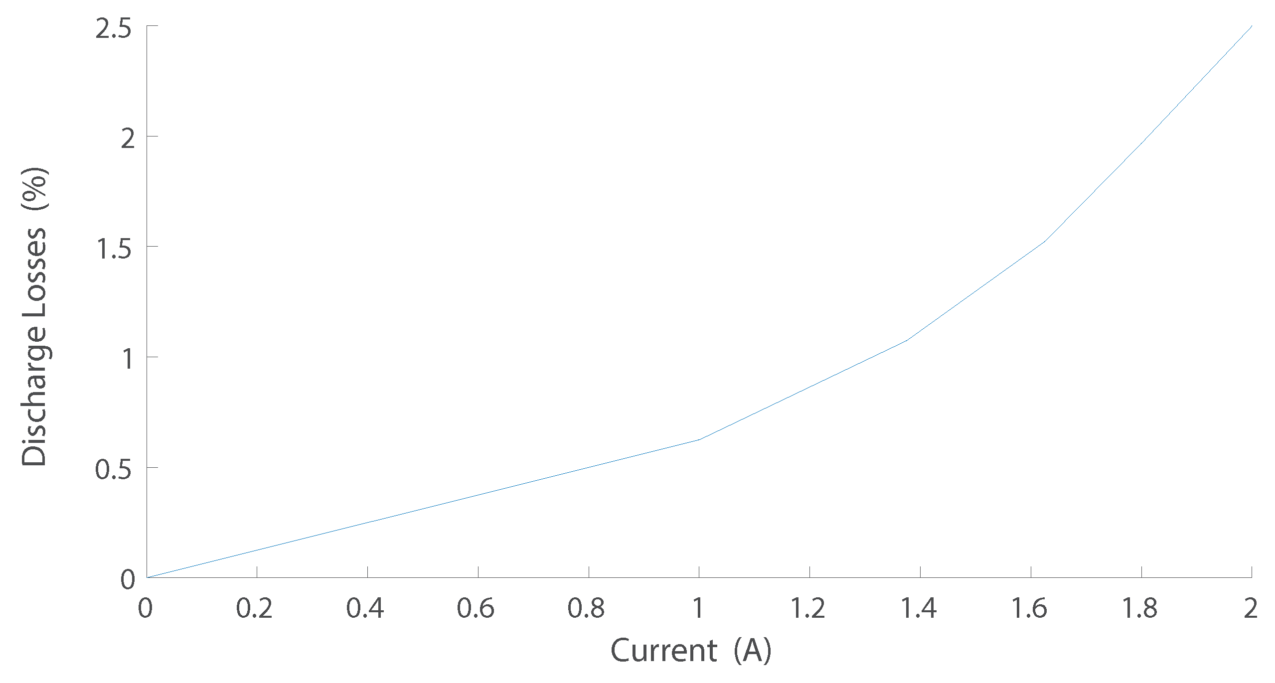
When discharging the battery, the general efficiency is not constant, as the regulation of the voltage supplied to the robot is left to the user and is done with a variable current, which can reach a value of up to 2 A. However, a relationship is defined between the current consumed by the robot and the efficiency of the discharge process. This relationship is shown in Figure 13.

5. Discussion

Although a Kalman filtering technique is reported in the literature as a SOC prediction tool, using software such as MATLAB, its behavior with an incorrect parameterization of the equivalent battery model is not widely reported in the literature in this field. The proposed DCC-EKF approach takes advantage of the EKF’s ability to predict quickly and accurately the SOC when the cell is at rest, or for a low flowing current, it reaches an maximum error in accuracy of about 5% for accurate initialization of the battery capacity and erroneous initialization of the SOC, even with a low current flowing through the cells and an inaccurate setting of the first-order battery parameters ( R p , C p and R t ), unlike the OCV, which requires a fully rested battery and 1 h to obtain an accurate result. In this paper, accuracy is defined as the difference between S O C r e f and ( S O ^ C ) for an average of 100 samples after result convergence:
δ = 1 100 · i = 4400 4500 | S O C r e f i S O ^ C i |
From Figure 11 it can be concluded that for practical purposes, the EKF should never be used alone, and should either be coupled with another algorithm, or require a regular update of the cell parameters, as they evolve over time. Nevertheless, the EKF function represents an asset that can be used to its advantage. It allows the user to take advantage of its excellent behavior when the batteries are at rest, as the filter converges directly after a few minutes for a prediction error of less than 5% for an SOC between 80% and 35%, and then the CC method is used, which allows the SOC to be accurately monitored and kept stable throughout the discharge process. This method replaces the CC-OCV method that is usually applied in commercial products and offers an increased prediction accuracy. Whether the parameters are correct or not, the SOC is accurately predicted in record time, even with noisy measurements, which is the main advantage of this hybrid CC algorithm.
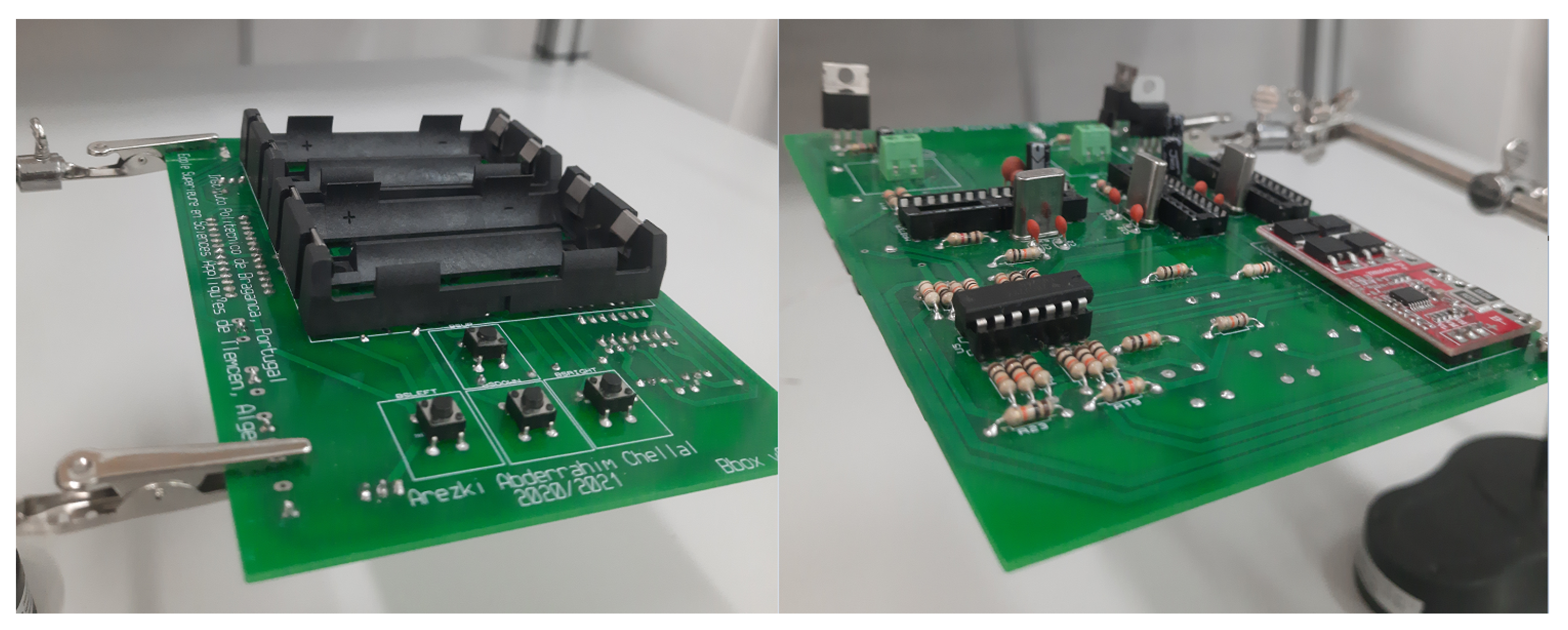
The overall product efficiency is defined as the average efficiency between the component consumption efficiency, the charging process efficiency and discharging process efficiency, which is 96.15%, 90.38% and 93.60%, respectively. The discharge process efficiency was calculated considering the maximum value (2.5%) with the component consumption. The overall efficiency of the prototype is therefore 94.38%. The developed printed circuit board (PCB), shown in Figure 14, can be placed and connected to the overall system. This prototype can also be connected to small solar-powered systems, either with robots or other systems.

6. Conclusions and Future Work

The aspect of energy management has always been an important aspect in electrical and energetic systems. In mobile systems, whether they are large systems such as hybrid vehicles or small systems such as mobile robots and smartphones, the battery is the only source of energy on which they can rely. It is, therefore, very important to optimize the use of this stored energy, which can be done by knowing the precise state of charge of each cell in the battery pack. The developed board has several functions, to monitor the batteries, manage the charging and discharging cycle, and to increase its life-span. It relies on accurate measurement of the current and voltage only, even in a noisy environment. The proposed architecture can offer an initializable black box solution, which is easy to integrate into any battery-powered device, thanks to its small size of 149 mm × 100 mm, a relatively good accuracy, compared to already marketed products of about 5% on average, and low cost, which is estimated through the components purchase cost and PCB manufacturing of EUR 32.
The DCC-EKF approach represents only one way to improve the online SOC prediction and monitoring task. Regarding future work, enabling SOC monitoring and prediction by the full EKF should be considered. To this end, validation of the implementation of different approaches to determine and update the online equivalent battery parameters using different methods proposed in the literature should be planned—mainly the double extended Kalman filter using 8-bit microcontrollers or more. The ESP32 is a very good candidate that is already being considered for use in future releases. Additionally, product minimization is an aspect that is defined as essential according to the aspiration of the product specification. The screen interaction of the product is easy for the user, but consumes power and is space consuming, added to this the push buttons. It will therefore be eliminated in favor of other modes of communication.

Author Contributions

Conceptualization, J.L., J.G. and H.M.; methodology, J.L., J.G.; software, A.A.C.; validation, A.A.C., J.L. and J.G.; formal analysis, A.A.C.; investigation, J.L. and A.A.C.; resources, J.L., J.G. and A.A.C.; data curation, J.G. and A.A.C.; writing—original draft preparation, A.A.C.; writing—review and editing, J.L., J.G.; V.P. and H.M.; visualization, J.L., J.G. and H.M.; supervision, J.L., J.G. and H.M.; project administration, J.L. and J.G.; funding acquisition, J.L. and J.G. All authors have read and agreed to the published version of the manuscript.

Funding

This paper is supported by ROBOSTEAM Erasmus+ KA201 Project with reference 2018-1-ES01-KA201-050939.

Institutional Review Board Statement

Not applicable.

Informed Consent Statement

Not applicable.

Data Availability Statement

Not applicable.

Conflicts of Interest

The authors declare no conflict of interest.

Abbreviations

The following abbreviations are used in this manuscript:
AEKFAscending extended Kalman filter
AIArtificial intelligence
AUVMicro autonomous underwater vehicle
BMSBattery management system
CCCoulomb counting
DCC-EKFDual coulomb counting extended Kalman filter
DEKFDual Extended Kalman Filter
EKFExtended Kalman filter
I2CInter-Integrated Circuit
KFKalman filter
Li-NMCLithium Nickel Manganese Cobalt Oxid
OCVOpen circuit voltage
PCBPrinted circuit board
SOCState of charge
SOHState of health
SOFState of function
UAVUnmanned aerial vehicle

References

  1. Castillo-Zamora, J.J.; Camarillo-Gómez, K.A.; Pérez-Soto, G.I.; Rodríguez-Reséndiz, J.; Morales-Hernández, L.A. Mini-AUV Hydrodynamic Parameters Identification via CFD Simulations and Their Application on Control Performance Evaluation. Sensors 2021, 21, 820. [Google Scholar] [CrossRef] [PubMed]
  2. Watson, S.A.; Crutchley, D.J.; Green, P.N. The design and technical challenges of a micro-autonomous underwater vehicle (μAUV). In Proceedings of the 2011 IEEE International Conference on Mechatronics and Automation, Beijing, China, 7–10 August 2011; pp. 567–572. [Google Scholar]
  3. Reis, R.; dos Santos, F.N.; Santos, L. Forest robot and datasets for biomass collection. In Proceedings of the Fourth Iberian Robotics Conference, Porto, Portugal, 20–22 November 2019; Springer: Cham, Switzerland, 2019; pp. 152–163. [Google Scholar]
  4. Megnafi, H.; Medjati, W.Y. Study and Assembly of Quadrotor UAV for the Inspection of the Cellular Networks Relays. In Proceedings of the International Conference in Artificial Intelligence in Renewable Energetic Systems, Tipaza, Algeria, 22–24 December 2020; Springer: Cham, Switzerland, 2020; pp. 659–668. [Google Scholar]
  5. Lièvre, A. Développement d’un Système de Gestion de Batterie Lithium-Ion à Destination de VéHicules “Mild Hybrid”: Détermination des Indicateurs d’état (SoC, SoH et SoF). Ph.D. Thesis, Université Claude Bernard-Lyon I, Villeurbanne, France, 2015. [Google Scholar]
  6. Hu, X.; Li, S.; Peng, H. A comparative study of equivalent circuit models for Li-ion batteries. J. Power Sources 2012, 198, 359–367. [Google Scholar] [CrossRef]
  7. Haifeng, D.; Xuezhe, W.; Zechang, S. A new SOH prediction concept for the power lithium-ion battery used on HEVs. In Proceedings of the 2009 IEEE Vehicle Power and Propulsion Conference, Dearborn, MI, USA, 7–11 September 2009; pp. 1649–1653. [Google Scholar]
  8. Leng, F.; Tan, C.M.; Pecht, M. Effect of temperature on the aging rate of Li ion battery operating above room temperature. Sci. Rep. 2015, 5, 12967. [Google Scholar] [CrossRef] [PubMed] [Green Version]
  9. Micea, M.V.; Ungurean, L.; Cârstoiu, G.N.; Groza, V. Online state-of-health assessment for battery management systems. IEEE Trans. Instrum. Meas. 2011, 60, 1997–2006. [Google Scholar] [CrossRef]
  10. Bonani, M.; Longchamp, V.; Magnenat, S.; Rétornaz, P.; Burnier, D.; Roulet, G.; Mondada, F. The marXbot, a miniature mobile robot opening new perspectives for the collective-robotic research. In Proceedings of the 2010 IEEE/RSJ International Conference on Intelligent Robots and Systems, Taipei, Taiwan, 18–22 October 2010. [Google Scholar]
  11. Megnafi, H.; Chellal, A.A.; Benhanifia, A. Flexible and Automated Watering System Using Solar Energy. In Proceedings of the International Conference in Artificial Intelligence in Renewable Energetic Systems, Tipaza, Algeria, 22–24 December 2020; Springer: Cham, Switzerland, 2020. [Google Scholar]
  12. Brito, T.; Pereira, A.I.; Lima, J.; Valente, A. Wireless sensor network for ignitions detection: An IoT approach. Electronics 2020, 9, 893. [Google Scholar] [CrossRef]
  13. UM11421 RDDRONE-BMS772 reference design. In Rev. 1–12 June 2020/User Manual; NXP: Nijmegen, The Netherlands, 2020; pp. 4–5.
  14. DSPH3059HD26. Rechargeable Smart Lithium Ion Battery Pack-PH3059HD26; Inspired Energy: Kirkham, UK, 2020. [Google Scholar]
  15. Spagnol, P.; Rossi, S.; Savaresi, S.M. Kalman filter SoC estimation for Li-ion batteries. In Proceedings of the 2011 IEEE International Conference on Control Applications (CCA), Denver, CO, USA, 28–30 September 2011; pp. 587–592. [Google Scholar]
  16. Knauff, M.C. Kalman Filter Based State of Charge Estimation for Valve Regulated Lead Acid Batteries in Wind Power Smoothing Applications. Ph.D. Thesis, Drexel University, Philadelphia, PA, USA, February 2013. [Google Scholar]
  17. Mastali, M.; Vazquez-Arenas, J.; Fraser, R.; Fowler, M.; Afshar, S.; Stevens, M. Battery state of the charge estimation using Kalman filtering. J. Power Sources 2013, 239, 294–307. [Google Scholar] [CrossRef]
  18. Zhang, C.; Jiang, J.; Zhang, W.; Sharkh, S.M. Estimation of state of charge of lithium-ion batteries used in HEV using robust extended Kalman filtering. Energies 2012, 5, 1098–1115. [Google Scholar] [CrossRef]
  19. Taborelli, C.; Onori, S.; Maes, S.; Sveum, P.; Al-Hallaj, S.; Al-Khayat, N. Advanced battery management system design for SOC/SOH estimation for e-bikes applications. Int. J. Powertrains 2016, 5, 325–357. [Google Scholar] [CrossRef]
  20. Kim, D.; Koo, K.; Jeong, J.J.; Goh, T.; Kim, S.W. Second-order discrete-time sliding mode observer for state of charge determination based on a dynamic resistance li-ion battery model. Energies 2013, 6, 5538–5551. [Google Scholar] [CrossRef] [Green Version]
  21. Kashkooli, A.G.; Fathiannasab, H.; Mao, Z.; Chen, Z. Application of artificial intelligence to state-of-charge and state-of-health estimation of calendar-aged lithium-ion pouch cells. J. Electrochem. Soc. 2019, 166, A605–A615. [Google Scholar] [CrossRef] [Green Version]
  22. Chellal, A.A.; Lima, J.; Gonçalves, J.; Megnafi, H. Battery Management System For Mobile Robots based on an Extended Kalman Filter Approch. In Proceedings of the 2021 29th Mediterranean Conference on Control and Automation (MED), Bari, Italy, 22–25 June 2021; pp. 1131–1136. [Google Scholar]
  23. Chellal, A.A.; Lima, J.; Gonçalves, J.; Megnafi, H. Dual Coulomb Counting Extended Kalman Filter for Battery SOC Determination. In Proceedings of the International Conference on Optimization, Learning Algorithms and Applications, (OL2A), Bragança, Portugal, 19–21 July 2021. [Google Scholar]
  24. Erlangga, G.; Perwira, A.; Widyotriatmo, A. State of charge and state of health estimation of lithium battery using dual Kalman filter method. In Proceedings of the 2018 International Conference on Signals and Systems, (ICSigSys), Bali, India, 1–3 May 2018; pp. 243–248. [Google Scholar]
  25. Jiang, S. A Parameter Identification Method for a Battery Equivalent Circuit Model; SAE Technical Paper No. 2011-01-1367; SAE: Warrendale, PA, USA, 2011. [Google Scholar]
  26. Mc78xx/lm78xx/mc78xxa. 3-Terminal 1a Positive Voltage Regulator; Fairchild Semiconductor: Sunnyvale, CA, USA, 2001. [Google Scholar]
  27. Malvino, A.P.; Bates, D.J. Principes D’électronique: Cours et Exercices Corrigés, 3rd ed.; Dunond: Paris, France, 2016. [Google Scholar]
  28. Eggermont, L.D. Embedded Systems Roadmap 2002; Vision on Technology for the Future of PROGRESS; STW Technology Foundation: Utrecht, The Netherlands, 2002; p. 30. [Google Scholar]
  29. Kim, I.S. Nonlinear state of charge estimator for hybrid electric vehicle battery. Trans. Power Electron. 2008, 23, 2027–2034. [Google Scholar]
  30. Tian, Y.; Lai, R.; Li, X.; Xiang, L.; Tian, J. A combined method for state-of-charge estimation for lithium-ion batteries using a long short-term memory network and an adaptive cubature Kalman filter. Appl. Energy 2020, 265, 114789. [Google Scholar] [CrossRef]
  31. Campestrini, C.; Horsche, M.F.; Zilberman, I.; Heil, T.; Zimmermann, T.; Jossen, A. Validation and benchmark methods for battery management system functionalities: State of charge estimation algorithms. J. Energy Storage 2016, 7, 38–51. [Google Scholar] [CrossRef]
Figure 1. Simplified battery management system diagram.
Machines 09 00313 g001
Figure 2. System block diagram.
Machines 09 00313 g002
Figure 3. Electronic circuit diagram of the voltage measurements.
Machines 09 00313 g003
Figure 4. Electronic circuit diagram for power regulation, current measurement and energy control.
Machines 09 00313 g004
Figure 5. I2C bus connection principle.
Machines 09 00313 g005
Figure 6. Data 1—Master to slave microcontroller bus signal.
Machines 09 00313 g006
Figure 7. Data 2—Slave to master microcontrollers bus signal.
Machines 09 00313 g007
Figure 8. Results of the variable current discharge test: (a) SOC comparison between S O C r e f and S O ^ C with Extended Kalman Filter, and correct parameter initialization [22]. (b) SOC comparison between S O C r e f and S O ^ C with Dual Coulomb Counting Extended Kalman Filter.
Machines 09 00313 g008
Figure 9. Results of the variable current discharge test: (a) The absolute error with the standard deviation between S O C r e f and S O ^ C . (b) The average absolute error between the S O C r e f and S O ^ C .
Machines 09 00313 g009
Figure 10. Results of the variable current discharge test with the DCC-EKF approach.
Machines 09 00313 g010
Figure 11. Results of the constant current discharge test: (a) SOC comparison between S O C r e f and S O ^ C with Extended Kalman Filter, and wrong parameter initialization. (b) The absolute error between S O C r e f and S O ^ C . (c) SOC comparison between S O C r e f and S O ^ C Dual Coulomb Counting Extended Kalman Filter. (d) The absolute error between S O C r e f and S O ^ C with DCC-EKF.
Machines 09 00313 g011
Figure 12. On-mode display of cells 1, 2, 3 and 4 with a real SOC value of 77.25%, 71.10%, 55.02% and 9.51% respectively: (a.1a.4) Average SOC of the first 50 iteration. (b.1b.4) A few seconds after. (c.1c.4) approximately 1 min after [23].
Machines 09 00313 g012
Figure 13. Battery management system prototype discharge characteristics.
Machines 09 00313 g013
Figure 14. Printed Circuit Board with soldered components.
Machines 09 00313 g014
Table 1. EKF tuning parameters.
ParametersValues
Covariance SOC2.5 × 10 1
Covariance V p 0
Process noise SOC1
Process noise V p 1
Measurement noise1 × 10 5
Table 2. Voltage and current measurment accurancies.
SensorValue
Voltage resolution (LM324N)100 mV
Current resolution (ACS-712)40 mA
Publisher’s Note: MDPI stays neutral with regard to jurisdictional claims in published maps and institutional affiliations.