Article

Approximation of Non-Linear Rotor Dynamic Resonance Behavior of Vertically Aligned Hydro-Units Guided by Tilting-Pad Bearings

1
Institute of Tribology and Energy Conversion Machinery, Clausthal University of Technology, 38678 Clausthal-Zellerfeld, Germany
2
G+R-S Bearings + Rotor Dynamics, 74523 Schwäbisch Hall, Germany
*
Author to whom correspondence should be addressed.
Machines 2021, 9(12), 334; https://doi.org/10.3390/machines9120334
Submission received: 8 November 2021 / Revised: 29 November 2021 / Accepted: 1 December 2021 / Published: 4 December 2021
(This article belongs to the Special Issue Tilting Pad Journal Bearings: State of the Art)

Abstract

:
Dynamic analyses of vertical hydro power plant rotors require the consideration of the non-linear bearing characteristics. This study investigates the vibrational behavior of a typical vertical machine using a time integration method that considers non-linear bearing forces. Thereby, the influence of support stiffness and unbalance magnitude is examined. The results show a rising influence of unbalance on resonance speed with increasing support stiffness. Furthermore, simulations reveal that the shaft orbit in the bearing is nearly circular for typical design constellations. This property is applied to derive a novel approximation procedure enabling the examination of non-linear resonance behavior, using linear rotor dynamic theory. The procedure considers the dynamic film pressure for determining the pad position. In addition, it is time-efficient compared to a time integration method, especially at high amplitudes when damping becomes small.

1. Introduction

Hydroelectric power plants are often equipped with vertical rotors. Today, these types of machines are commonly guided by tilting-pad journal bearings due to their excellent stability properties and tunable nominal bearing clearance. Most hydro units operate in the subcritical speed regime. Nevertheless, for the design and specification of the machine, as well as outstanding operation conditions, the knowledge of the resonance speed is of particular importance.
Due to the vertical alignment, no gravity forces are acting on the guide bearings, and thus the dynamic unbalance forces exceed the static forces in wide ranges of operation conditions, especially with an increasing rotor speed. The bearing stiffness of these nearly statically unloaded bearings significantly increases with the amplitude of shaft orbit and, consequently, the dynamic properties of the system depend on the unbalance excitation magnitude. Theoretical investigations show that the resonance speed increases with rising unbalance [1]. Furthermore, the resonance speed can differ between the run-up and the run-down procedure [1]. Aside from the impact of thermal effects, this property can be primarily attributed to the nonlinear increase in bearing stiffness.
For non-linear simulation of tilting-pad bearing forces, the pad movement must be known. This enables the calculation of the Reynolds equation based on relative movement between journal and pads. For consideration of the pad inertia the equations of motions must be solved [2,3,4,5,6]. Theoretical investigations of large hydro units indicate that the shaft orbit is nearly circular [3,4,5,6]. On the contrary, analyses of small size machines demonstrate that the orbit approaches the shaft movability curve for high amplitudes, e.g., [7,8,9]. Theoretical analyses on vertical rotor systems show the significant impact of bearing clearance on the resonance speed, as well as on the systems damping factor [10,11].
In this investigation the dynamic behavior of a typical larger-type vertical machine is studied considering non-linear bearing forces. Hereby, the influence of bearing clearance, bearing support stiffness and unbalance magnitude is examined. Based on the results, a method approximating non-linear behavior using a time-efficient linear rotor dynamics program is derived.

2. Materials and Methods

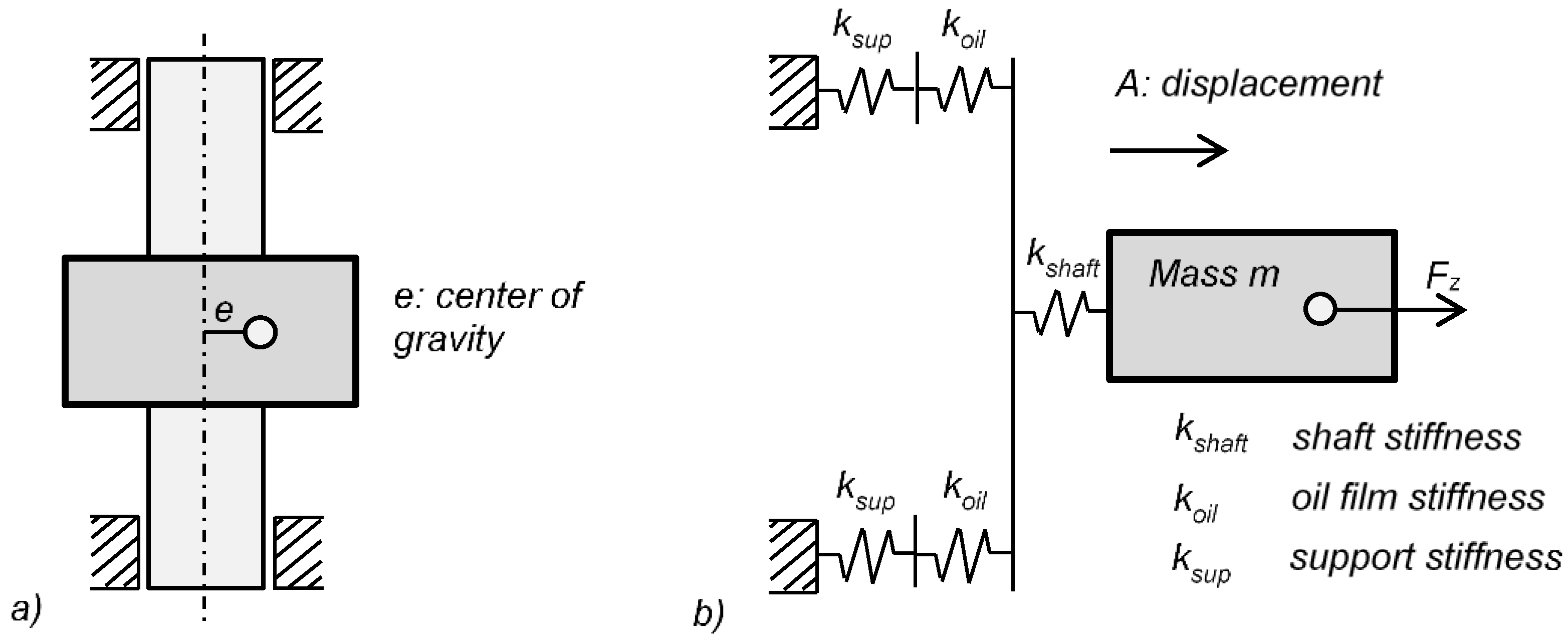
2.1. Rotor Modelling

The elastic shaft of the rotor is modelled by Finite Elements using Timoshenko beam theory with continuously distributed inertias [12]. Thereby, the shear factor according to [13] is used. That leads to the system of ordinary differential equations in inertial coordinates:
M x ¨ ( t ) + ( G ( ω ) + C ( ω , x s t a t ) ) x ˙ ( t ) + K ( ω , x s t a t ) x ( t ) = F ( t )
Herein, the mass matrix M, the gyroscopic and damping matrices G and C, the stiffness matrix K, as well as the displacement vector x are located on the left. The gyroscopic matrix is a function of angular rotor speed ω . Stiffness and damping of the journal bearings depend on rotor speed ω and displacement x s t a t and, consequently, the stiffness and damping matrix of the rotor bearing system also depends on it. The force vector F is located on the right-hand side of the equation. For linear rotor dynamic analyses, Equation (1) can be solved after x using a harmonic ansatz. The homogenous part of the equation can be used for Eigenvalue analyses, e.g., for the creation of Campbell diagrams.
To consider non-linear bearing characteristics, bearing forces are added as external forces acting on the rotor. A modified force vector F * contains bearing, unbalance, gyroscopic, gravity and damping forces:
M x ¨ ( t ) + K x ( t ) = F * ( t , ω , x )
The system behavior will be solved in the time domain using a numerical time integration method. Here, bearing forces will be updated with lateral journal displacement and velocity in each time step. Introducing a new state vector q = ( x , x ˙ ) T provides a first-order state space formulation of Equation (2).
q ˙ = A q + B F ˜ ( t , ω , q ) ,           F ˜ = ( F * 0 )
After a modal reduction, Equation (3) can be solved by a numerical time integration method. This study applies the trapezoidal rule according to [14]:
q n + 1 = q n + 0.5   Δ t   ( q ˙ ( t n , q n ) + q ˙ ( t n + 1 , q n + 1 ) )
Based on the last time step “n” the state vector at the current time step “n + 1” can be calculated. In this study a modified MATLAB solver ode23t is used. The entire rotor calculations are performed with an in-house code earlier introduced by the authors in [15].

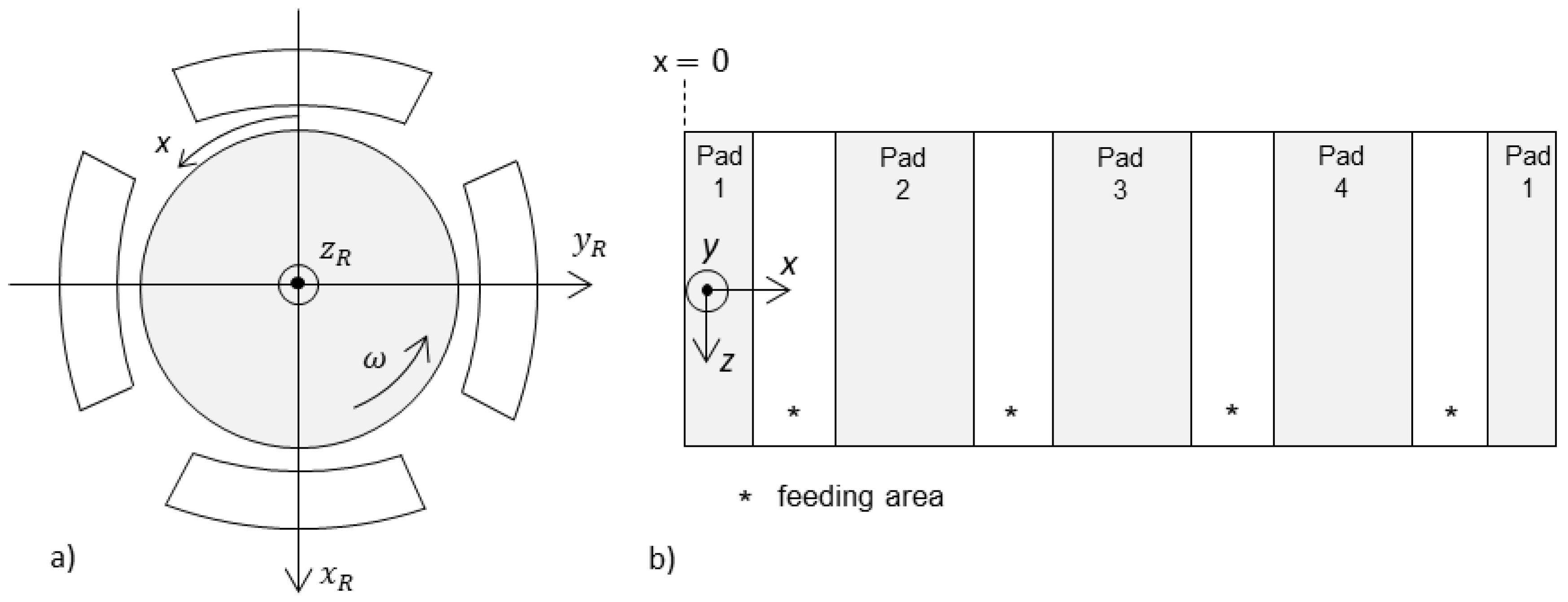
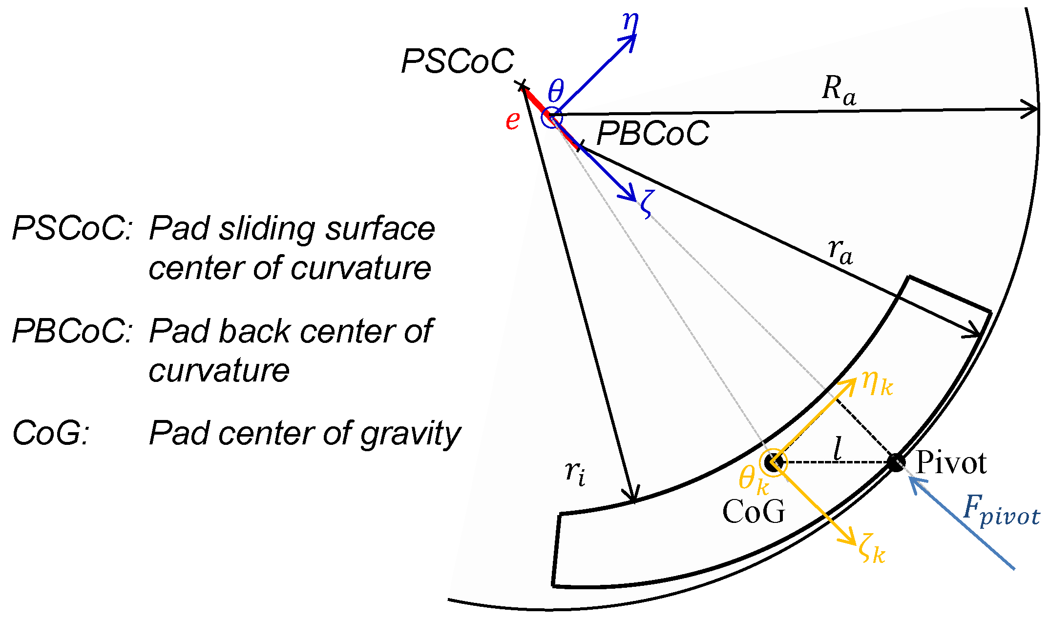
2.2. Non-Linear Bearing Modelling (NLIN)

Two-dimensional Reynolds equation describes oil flow in the lubricant gap:
x ( F 2 K x p x ) + z ( F 2 K z p z ) = U x [ ρ * ( h F 1 F 0 ) ] + t ( ρ * h )
Herein, F 0 , F 1 and F 2 are factors that consider the radial variable viscosity distribution in the lubricant film [16]:
F 0 = 0 h d y η ,           F 1 = 0 h y η d y ,           F 2 = 0 h y η ( y F 1 F 0 ) d y
where U is the sliding velocity of the shaft, h is the local gap height, ρ * is the local fill factor of the fluid film and η is the dynamic viscosity of the lubricant. Local turbulent flow is approximated by the coefficients K x and K z according to [17,18]. Figure 1 depicts the lubricant gap solution domain coordinate system ( x , y , z ) of Reynolds equation and the relation to the rotor coordinate system ( x R , y R , z R ).
A mass conserving algorithm based on JFO theory is used for solving Reynolds equation [19]. The algorithm described in [19] for the stationary case is extended for the consideration of the time dependency of the instationary case, for example [20]. The viscosity factors can be derived from solution of the three-dimensional energy equations considering the dissipation by friction, heat transfer in the oil film and heat conduction in journal and pads. The temperature distribution is calculated for a centered journal position for different rotor speeds at stationary rotation. A more comprehensive description of the theoretical models, in particular the energy equation can be found in [21,22].
Pad movability is predicted by solving the pad’s equations of motion for transversal and tilting directions. Figure 2 shows the pad coordinate system ( ζ , η , θ ) for a description of the transversal equations of motion.
The ( ζ , η , θ )-coordinate system is located in the bearing center. The ζ -axis is directed to pivot position and the θ -axis is in parallel to the axial bearing axis. For the description of the tilting motion a body-fixed ( ζ k , η k , θ k )-coordinate system is introduced at the pad’s center of gravity where the inertia tensor is constant. Tilting motion is described by the orientation angle φ θ of the ( ζ k , η k , θ k )-system relative to the ( ζ , η , θ )-system. Equations of motion for the mass m and the mass moment of inertia J θ of a single pad are as follows:
[ m m J θ ] ( ζ ¨ η ¨ φ ¨ θ ) = ( F ζ F η M θ ) o i l + ( F ζ F η l ζ F η + l η F ζ ) p i v o t
Right side of Equation (7) includes oil film and pivot forces and oil film and pivot moments with regard to the center of gravity of the pad, respectively. Equation (7) is transformed to a first-order state space formulation analogously to the procedure for Equations (2) and (3). For a given lateral and angular pad position and velocity at a certain time step, the equations can be solved according to Equation (4). The lubricant film thickness is a result of the relative position of journal and pads. Pivot forces are calculated by the relation between pivot stiffness and relative displacement at the pivot point:
F ζ = k p i v o t Δ ζ p i v o t           F η = k p i v o t Δ η p i v o t
Thus, the unsteady system behavior is determined by the numerical time integration of the rotor and pad motion. However, the calculation is continued until a quasi-stationary state is reached for a certain rotor speed.

2.3. Linear Bearing Modelling (LIN)

For linear dynamic analyses, the pad assembly method is applied according to [23,24]. Oil film stiffness and damping are calculated by a first-order perturbation of Reynolds equation. The pad is assumed to be massless; therefore, a resulting stiffness and damping of the series connection of oil film and pivot stiffness can be calculated. For this purpose, a harmonic oscillation of the pads is assumed that is synchronous to the shaft rotating frequency. The single-pad dynamic coefficients are vectorially assembled to an overall bearing stiffness and damping matrix which leads to the kc-model:
( F x F y ) = [ k x x k x y k y x k y y ] k ( x R y R ) + [ c x x c x y c y x c y y ] c ( x ˙ R y ˙ R )
Common rotor dynamics analyses use the kc-model for the consideration of the linearized bearing forces in equations of motion (1).

2.4. Approximation of Non-Linear Bearing Characteristics (QLIN)

The approach of the kc-model allows a simple exchange of bearing properties between the bearing manufacturer and the plant manufacturer. The aim of this section is to find a similar procedure for the non-linear system that allows the bearing calculation to be separated from the rotor calculation. It should also be applicable similar to the kc-model in a rotor dynamics program to prevent the time-consuming co-simulation with a bearing program. For this purpose, so called “global coefficients” are determined. Subsequently, global coefficients are identified by the subscript “g”. Non-linear investigations show that the orbit of the relative oscillation within the bearing is nearly circular, even for extreme amplitudes, as shown in Section 3.2. This property is related to limited stiffness of the pivot support and inertia of the rotor in general. Consequently, a circular orbit for the approximation of the bearing forces is assumed. Figure 3 shows a snapshot of the kinetics during a circular shaft movement. Radial and tangential film forces F r and F t , journal orbit radius e r , and tangential velocities e ˙ t can be used for the determination of the global stiffness and damping characteristics.
The global stiffness k g , r in direction of journal orbit radius e r and the main damping c g , t in direction of tangential orbit velocity e ˙ t are calculated according to Equation (10):
k g , r = F r e r ,           c g , t = F t e ˙ t
Based on Equation (10), the relation of the stiffness and damping matrix in cartesian x-y-coordinates is established in the following. The assumption of a circular orbit leads to the demand that the 2 × 2 stiffness and damping matrices are invariant due to rotations φ of the coordinate system, as expressed in Equation (11):
k g = T ( φ )   k g   T ( φ ) T ,       c g = T ( φ )   c g   T ( φ ) T ,             0 φ 2 π ,           T = [ cos ( φ ) sin ( φ ) sin ( φ ) cos ( φ ) ]
This is fulfilled if main stiffness and damping coefficients, in both directions, are equal and the cross-coupling coefficients are zero or equal in magnitude but with opposite signs:
k g , y y = k g , x x ,           k g , x y = k g , y x ,           c g , x x = c g , y y ,           c g , y x = c g , x y
Finally, stiffness and damping matrices of a particular orbit radius and rotor speed result in:
k g = [ k g , x x k g , x y k g , y x k g , y y   ] = [ F r / e r 0 0 F r / e r ] ,           c g = [ c g , x x c g , x y c g , y x c g , y y   ] = [ F t / e ˙ t 0 0 F t / e ˙ t ]
For this purpose, a circular journal movement must be specified using a journal bearing calculation program. Despite the circular journal orbit, the forces may differ from a circular shape. The coefficients are determined for each point on the orbit and averaged over one revolution. Figure 4 exemplarily shows the impact of rotor speed and orbit radii on bearing stiffness and damping coefficients.
The bearing stiffens with rising rotor speeds and orbit radii. The damping reduces with rotor speed in the investigated range. For each rotor speed a maximum damping value exists at a particular radius. With a rising orbit radius, the damping initially increases. After passing the maximum value the damping decreases. Particularly disadvantageous is the increasing stiffness with the simultaneous decrease in damping. This leads to a reduction in the relative damping of the system.
Global coefficients can easily be used in rotor dynamic analyses by updating the coefficients with a bearing orbit as demonstrated in Figure 5. The coefficients are iteratively adjusted until the change in the journal orbit radius satisfies a criterion of convergence. In the following, this procedure is referred to as quasilinear analysis (QLIN). It is recommended to use the solution of the last operating point as the initial condition of the next speed step to enable a path tracing in the simulation.
In [25], a similar but different approach is presented using the integrated mean value of local bearing stiffness determined for each journal eccentricity. It is assumed that the stiffness is independent of the load direction using the mean value of the load on pad and load between pad configurations. The authors conclude that this is a good approximation for bearings with many pads. Additionally, the method presented here considers the influence of the squeeze film term of Reynolds Equation (5) on the pad position.

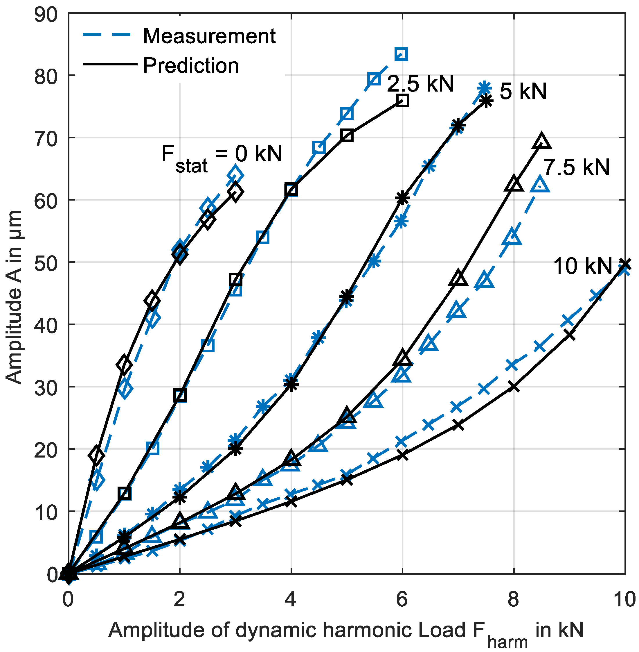
2.5. Validation of the Non-Linear Bearing Model (NLIN)

For validation of the non-linear bearing model a comparison with measurement of a 5-tilting-pad bearing is done. Table 1 shows the parameter of the bearing.
Figure 6 compares measured [26] and non-linearly (NLIN) predicted amplitudes for different static and dynamic loads. The load is directed between the pads and has a static part F s t a t and a dynamic, harmonic part F h a r m . Thus, the total force amounts to F = F s t a t + F h a r m · sin ( ω · t ) . Measurement and prediction match very well, both in general characteristic and in absolute values.

3. Results

3.1. Preliminary Considerations

The basics of the resonance shift of a rotor-bearing system due to the increase in the oil film stiffness with higher amplitudes can be explained using a simple rotor model. The rotor model in Figure 7 consists of the rotor mass m , the elastic shaft k s h a f t , the oil film stiffness k o i l and the bearing support stiffness k s u p .
For calculating the natural frequency of the system, the resulting stiffness:
k r e s = 1 1 / ( 2 k o i l ) + 1 / ( 2 k s u p ) + 1 / ( k s h a f t ) ,
is formed, whereas the lowest value for k o i l is the film stiffness of the bearing center. Considering all these elasticities of the system, the lower resonance speed ω 0 , l can be calculated by:
ω 0 , l = k r e s / m = 1 1 / ( 2 k o i l ) + 1 / ( 2 k s u p ) + 1 / ( k s h a f t ) 1 m .
Oil film stiffness k o i l increases with rising amplitudes of the journal. For high amplitudes the oil film stiffness can be assumed as rigid and the upper resonance speed becomes:
ω 0 , u = 1 1 / ( 2 k s u p ) + 1 / ( k s h a f t ) 1 m .
Finally, the formula for the resonance ratio ω 0 , l / ω 0 , u is:
ω 0 , l ω 0 , u = 1 2 k s u p + 1 k s h a f t / 1 2 k o i l + 1 2 k s u p + 1 k s h a f t .
Its solution is depicted in Figure 8 and depends on the both stiffness ratios: k o i l / k s h a f t and k s u p / k s h a f t . The resonance ratio is independent of the rotor mass. The curves in Figure 8 show the shift of resonance with oil film stiffness (<100%) to the upper resonance (=100%). A non-linear analysis should be considered for a low ratio of k o i l / k s h a f t and a high ratio of k s u p / k s h a f t due to a high possible shift of the resonance speed.
The upper and lower resonance speed of an arbitrary rotor system described by Equation (1) can be calculated in a similar way. The lower resonance speed is reached if film stiffness and damping of the bearing center is used in the calculation. Since bearing stiffness is composed of film stiffness and pivot stiffness, the upper resonance speed is calculated if film stiffness is assumed to be rigid and only the pivot elasticity remains. For this purpose, the pivot stiffnesses k p i v o t , i are summarized vectorially and averaged appropriately, which leads to the resulting isotropic bearing stiffness for high orbit radii:
k b e a r i n g 0.5 i = 1 N p a d k p i v o t , i · cos 2 ( τ p i v o t , i )
Herein, τ p i v o t , i is the angular position of the pivot. The factor 0.5 in Equation (18) is applied because approximately half the number of pads are loaded for high amplitudes. On the opposite side, the film thickness of unloaded pads is high. Therefore, their film stiffness is low, and pivot stiffness can be neglected for the circular orbit. Equation (18) proved to be well suited for the consideration of the pivot elasticity in a linear analysis. The result for an 8-pad bearing with identical pads is k b e a r i n g = 2 k p i v o t and for a 4-pad bearing k b e a r i n g = k p i v o t .

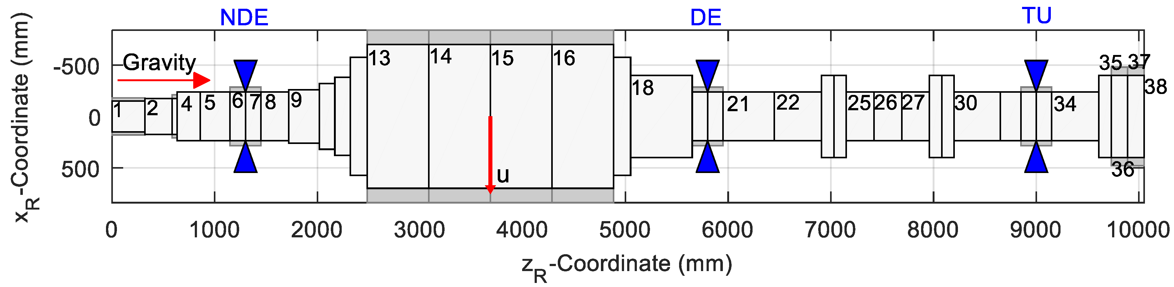
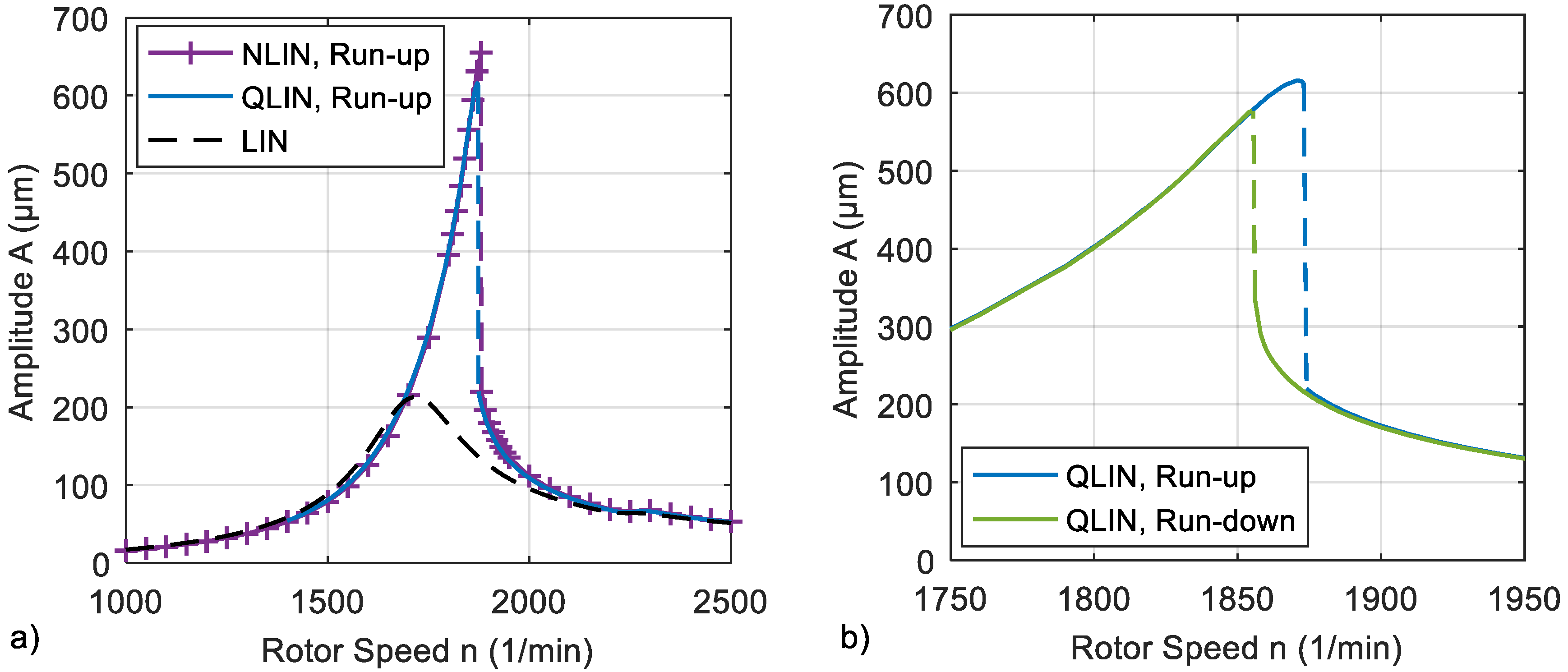
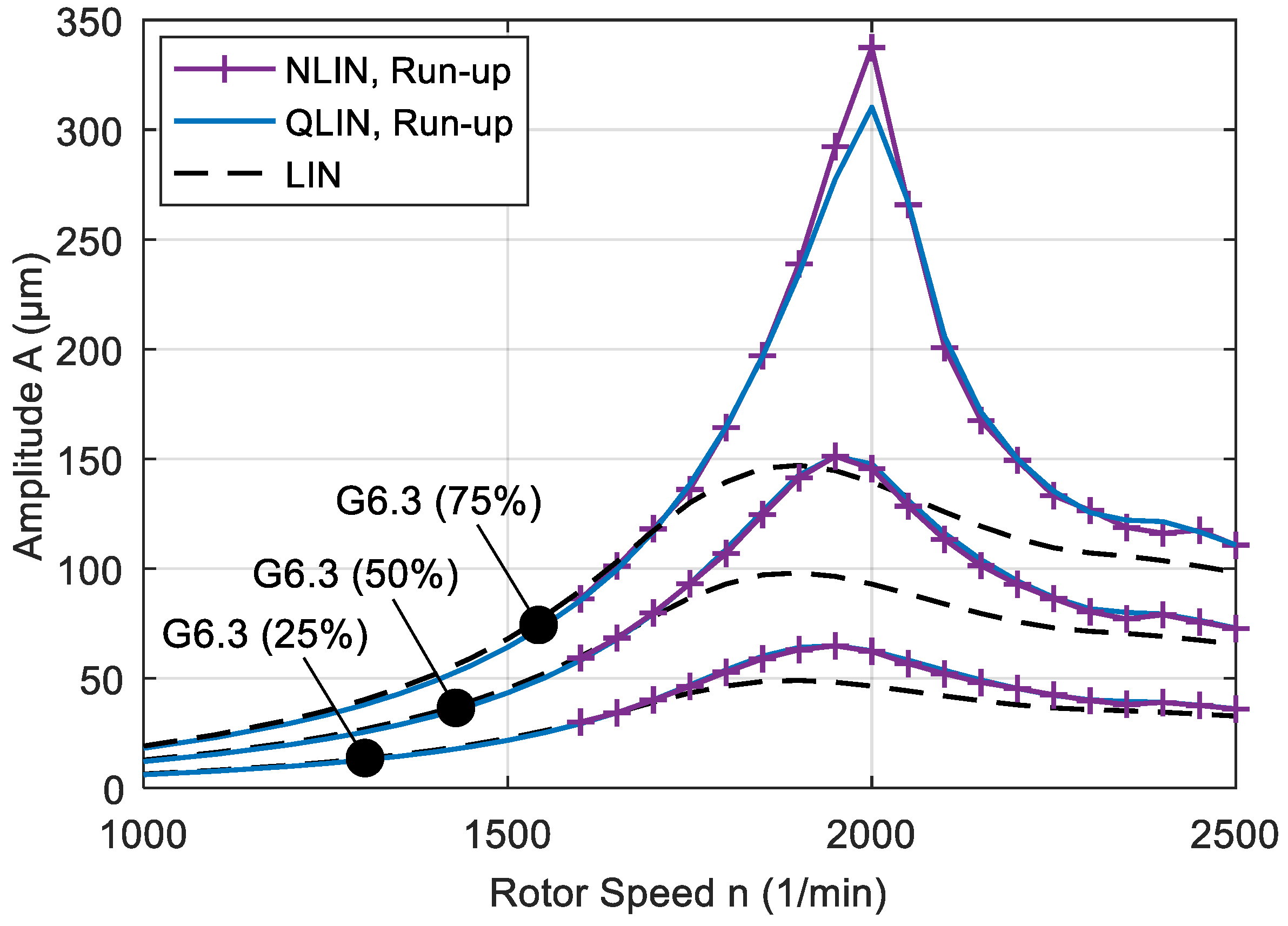
3.2. Investigation of a Hydro Plant Rotor

The rotor model of the investigated fictitious hydro unit is depicted in horizontal representation in Figure 9. The active generator length extends over the sections 13 to 16 and the turbine is located in sections 35 to 37. An unbalance is placed in the middle of the generator on node 15.
In this design, three identical tilting-pad bearings with eight pads guide the powertrain. The none-drive-end (NDE), the drive-end (DE), and the turbine bearing (TU) are located on nodes 7, 20, and 33. Table 2 includes the most important rotor data.
The bearing design parameters are summarized in Table 3. Four different bearing variants are investigated. The geometry of the first three bearing variants can be transferred into each other by adjusting the bearing clearance, which modifies the pad preload. The fourth variant is identical to variant 1 but has a stiffer bearing support.
In the first instance, all investigations are carried out using the variant 1 bearing. Figure 10 depicts the natural frequencies and their damping in a Campbell diagram. The stiffness and damping of the bearing center are used. While the bearing stiffness increases with rotor speed, the damping decreases. The modifications are most significant at low speeds. Therefore, the eigenvalues also change predominantly in the low speed range. The first critical speed is located at n     1700   rpm . Figure 10 additionally shows the shape forms of the eigenfrequencies for the first and second critical speeds. The shape of the first eigenvalue indicates that it can be excited by an unbalance located at the generator, whereas the second eigenvalue is particularly excited by a turbine unbalance. The second critical speed is reached at n     2250   rpm . Since the machine operates in the subcritical regime, the first critical speed is of practical importance. For these reasons, an unbalance located at the generator (node 15) is assumed. To study the influence of the unbalance, the balance quality grade G6.3 is used as reference, which leads to an unbalance of u = 3.6   m · kg . The particular unbalance is specified as a percentage value of the G6.3 unbalance. Eigenvalues change at low speeds.
Figure 11 includes the Bode plot for the absolute generator and turbine and the relative bearing vibrations due to the unbalance of G6.3 (100%). The maximum resonance amplification is reached at a rotor speed of n = 1720 1/min. At a rotor speed of n = 2240 1/min the second resonance is reached. All amplitudes are given as 0-Peak value.
Figure 12a compares the generator amplitudes of the linear (LIN) and non-linear solution for the unbalance G6.3 (40%) and the variant 1 bearings in a run-up simulation. For verification purposes, the nonlinear (NLIN) solution and the quasi-linear (QLIN) solution are depicted. A very good approximation quality of the quasi-linear analysis can be determined. The resonance speed increases from n = 1720 1/min to n = 1880 1/min compared to the linear analysis. Amplitudes are much higher than in the linear solution. After passing the resonance speed the amplitude “jumps” in the supercritical regime with low level amplitudes. The dashed line marks the path of the jump. In Figure 12b the behavior of the run-up and the run-down can be seen. Between the run-up and the run-down a hysteresis can be observed. Coming from the supercritical regime, the resonance speed for the run-down is lower than the resonance speed for the run-up because the bearings are less stiff at smaller amplitudes. A hysteresis only occurs when the unbalance is sufficiently large.
Relative bearing amplitudes and bearing forces are depicted in Figure 13. They correspond to the rotor amplitudes of Figure 12. For an unbalance of G6.3 (40%) the relative bearing amplitudes of the NDE and the DE bearing already become larger than the nominal bearing clearance of Δ R = 150   µ m . The maximum bearing load is more than three times higher than the linearly predicted one. Amplitudes and bearing loads of the TU-bearing are much lower than in the other two bearings.
A circular orbit is assumed for the quasi-linear analysis. The calculation results of the nonlinear analysis are now used to verify this assumption. Figure 14 shows the absolute and the relative journal orbit in the DE-bearing for the balance quality G6.3 (40%). Two operation points are depicted, the first is in the subcritical speed regime and the second is at resonance speed. The relative journal orbit is smaller than the absolute journal orbit because of the elastic flexibility of the bearing support. At the subcritical operation point, absolute and relative journal orbits are smaller than the bearing clearance. A circular orbit can be observed. Even at the rotor speed of maximum resonance amplification the orbit remains circular, although the relative orbit is larger than the nominal bearing clearance. This behavior is feasible due to the pivot elasticity in particular. Consequently, the assumption of a circular orbit is proven in the investigated range.
The impact of unbalance on the characteristics of resonance speed is depicted in Figure 15 for the different 8-tilting-pad bearing design parameter. Variants 1, 2 and 3 differ only in bearing clearance and, therefore, they have the same upper limit of n = 2031 1/min. The smaller the clearance, the higher the lower limit of the resonance speed becomes. Variant 4 features the same clearance as variant 1 but a stiffer bearing support. Consequently, upper and lower limits are higher. According to the deliberations of Section 3.1 the possible resonance shift is bigger than the one of variant 1. Generally, the maximum resonance speed comes close to the upper limit. The resonance speed cannot be calculated for any desired high unbalance, because the damping becomes very small and, consequently, amplitudes become very high.
When damping disappears at high unbalances, a quasi-stationary condition can no longer be determined. However, a quick run-up through the resonance speed may still be possible and can prevent a bearing damage.

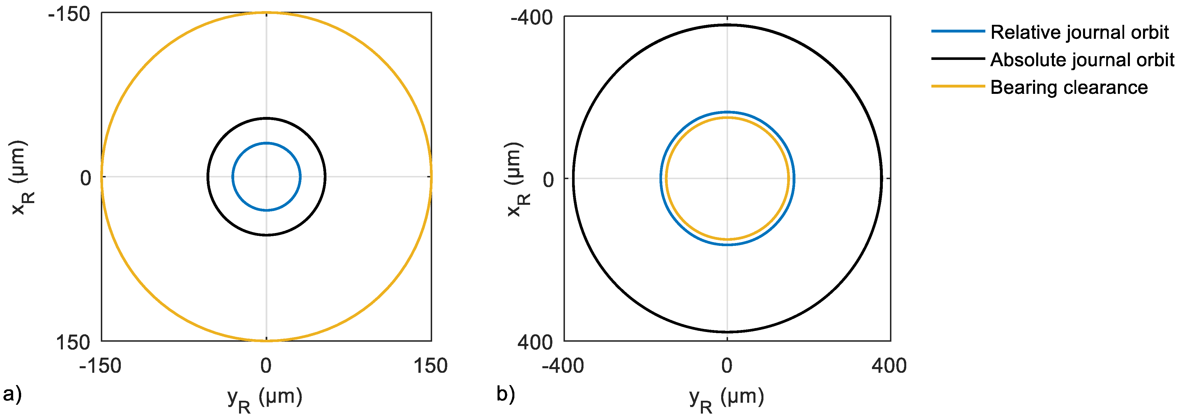
3.3. Application to Non-Cricular Orbits

Finally, an academic case is investigated in which the assumption of a circular journal motion is no longer valid. For this, the number of pads is reduced to four and the pivot stiffness is increased by 100 times. Table 4 includes the design parameter of the 4-tilting-pad bearing. All other parameters agree with those of the 8-tilting-pad bearings in Table 3.
Figure 16 compares the absolute amplitudes of the NDE bearing for different analysis types and unbalances. Since a deviation from the circular orbit is expected, the time averaged orbit radius is evaluated for the non-linear analysis. Resonance magnification rises at a greater rate, with the increasing unbalance. The quasi-linear analysis still provides a good approximation of the non-linear case.
Absolute and relative journal orbits at the maximum resonance amplification and maximum examined unbalance are depicted in Figure 17. As expected, the non-linear calculation deviates from the circular orbit and fits the journal movability curve of the four pads. Quasilinear analysis predicts a relative journal orbit that is alternately slightly larger or smaller. Overall, the approximation quality proves to be very accurate.

4. Discussion

The resonance speed of vertical aligned rotors can exhibit a significant dependence on unbalance due to the stiffening of the bearing with increasing deflection. An upper and a lower limit enclose the range of resonance speeds. These limits can be calculated by linear rotor dynamic analyses. While the lower limit is obtained by taking into account the lubricant film stiffness of the bearing center, the upper limit can be estimated by neglecting the film stiffness. The actual resonance speed is located within this range and depends on the unbalance. It can be estimated using linear rotor dynamics and global bearing stiffness and damping. Assuming a circular journal orbit, the global coefficients can be calculated with a typical thermo-hydrodynamic bearing code. The benefit of this procedure is the separation of rotor and bearing analysis which enables an easy exchange of the bearing properties between two parties, for example bearing and plant manufacturer. Furthermore, it provides the possibility of evaluating the non-linear bearing properties without the execution of a rotor dynamic analysis.
The method is also faster compared to a time integration, especially if system damping becomes small in the area of maximum resonance magnification. The exact amount of time saved depends on many factors. Non-linear analysis takes longer if the system has more degrees of freedom, if the damping ratio becomes low or if the system becomes stiff in the mathematical sense. The computation time of the quasi-linear analysis is nearly completely assigned to the determination of the global coefficients. The subsequent calculation of the Bode diagram, on the other hand, consumes no significant computing time. Therefore, the time saving of the quasi-linear analysis increases with the number of calculated operating points. In the calculations performed here, the quasi-linear analysis was up to 50 times faster than the non-linear analysis for a single Bode plot. If more operating points are calculated for the same bearing, the quasi-linear analysis correspondingly becomes more efficient.
In this study, a typical hydro plant rotor guided by tilting-pad bearings was investigated, whereby different bearing variants were examined. The variants differ in bearing clearance, bearing support stiffness and the number of pads. With regard to the design parameters, it is almost exclusively the elasticity ratios of the lubricant film, shaft and support stiffness that are decisive in determining the resonance shift. Good results can be achieved with the approximation procedure if the number of pads is high and the pivot stiffness is low, as this effects nearly circular orbits. This is the case for many large-type machines. The error theoretically becomes greater if the number of pads is small and at the same time the pivot stiffness is high, or if static forces dominate over the unbalance forces. Nevertheless, the analysis produces a good approximation of the synchronous amplitude, even in the case of non-circular orbits, as shown for the four-pad tilting-pad journal bearing in this study.

Author Contributions

Conceptualization, D.V., T.H., A.S.; methodology, D.V.; software, D.V., T.H.; investigation, writing, and visualization, D.V., T.H., A.S.; supervision and funding acquisition, H.S. All authors have read and agreed to the published version of the manuscript.

Funding

This research was funded by the German Federal Ministry of Economic Affairs and Energy. The financial support was assigned by the Industrial Research Association (AiF e.V.) in project number IGF 19023 N/1.

Acknowledgments

The authors thank the expert committees of the German research community FVA e.V. for the technical and scientific steering of this research project.

Conflicts of Interest

The authors declare no conflict of interest.

Nomenclature

Aorbit radius
Asystem matrix of the state space model
Binput matrix of the state space model
cdamping coefficient
Cdamping matrix
e r ,   e ˙ t journal orbit radius and tangential orbit velocity
F r ,   F t film forces in radial and tangential direction
F0, F1, F2viscosity factors
F ζ , F η film forces/pivot forces in ζ and η direction
Fforce vector
F*modified force vector for non-linear analysis
Ggyroscopic matrix
hlocal gap height
J θ mass moment of inertia of a single pad
k stiffness coefficient
k o i l oil film stiffness
k b e a r i n g bearing stiffness
k p i v o t pivot stiffness
k r e s resulting stiffness
k s h a f t shaft stiffness
k s u p support stiffness
K x , K z factors for turbulent flow approximation
Kstiffness matrix
l ζ , l η distance from pivot to center of gravity of the pad in ζ and η direction
mmass
M θ , o i l film moment with regard to the center of gravity of the pad
Mmass matrix
nrotor speed
N p a d number of pads
pfilm pressure
qstate vector of the state space model
ttime
Trotation matrix
u unbalance
Usliding velocity of the shaft
xdisplacement vector
x, y, zcoordinates of the lubricant gap solution domain
xR, yR, zRcoordinates of the rotor system
ζ ,   η ,   θ coordinates for the transversal motion of the pads
ζ k , η k , θ k coordinates for the tilting motion of the pads
η dynamic viscosity of the lubricant
ρ * local fill factor
ω angular rotor speed
ω 0 angular eigenfrequency
τ p i v o t , i angular pivot position of the i-th pad

Abbreviations

DEdrive end
NDEnon-drive end
TUturbine end
LINlinear analysis
NLINnon-linear analysis
QLINquasi-linear analysis
G6.3balance quality G6.3 grade

References

  1. Merker, H.-J. Über den Nichtlinearen Einfluß von Gleitlagern auf die Schwingungen von Rotoren. Ph.D. Thesis, University of Karlsruhe, Karlsruhe, Germany, 1981. [Google Scholar]
  2. Ma, L.-F.; Zhang, X.-Z. Numerical Simulation of Nonlinear Oil-Film Forces of Tilting-Pad Guide Bearing in Large Hydro-unit. Int. J. Rotating Mach. 2000, 6, 345–353. [Google Scholar] [CrossRef]
  3. Gadangi, R.K.; Palazzolo, A.B.; Kim, J. Transient Analysis of Plain and Tilt Pad Journal Bearings Including Fluid Film Temperature Effects. J. Tribol. 1996, 118, 423–430. [Google Scholar] [CrossRef]
  4. Abu-Mahfouz, I.; Adams, M.L. Numerical Study of Some Nonlinear Dynamics of a Rotor Supported on a Three-Pad Tilting Pad Journal Bearing (TPJB). J. Vib. Acoust. 2005, 127, 262–272. [Google Scholar] [CrossRef]
  5. Shi, Z.; Jin, Y.; Yuan, X. Influence of pivot design on nonlinear dynamic analysis of vertical and horizontal rotors in tilting pad journal bearings. Tribol. Int. 2019, 140, 105859. [Google Scholar] [CrossRef]
  6. Springer, H. Nichtlineare Schwingungen Schwerer Rotoren mit Vertikaler Welle und Kippsegmentradiallagern. Forsch. Im Ing. A 1979, 45, 119–132. [Google Scholar] [CrossRef]
  7. Nässelqvist, M.; Gustavsson, R.; Aidanpää, J.-O. Experimental and Numerical Simulation of Unbalance Response in Vertical Test Rig with Tilting-Pad Bearings. Int. J. Rotating Mach. 2014, 10, 309767. [Google Scholar] [CrossRef]
  8. Cha, M.; Glavatskih, S. Nonlinear dynamic behaviour of vertical and horizontal rotors in compliant liner tilting pad journal bearings: Some design considerations. Tribol. Int. 2015, 82, 142–152. [Google Scholar] [CrossRef]
  9. Synnegård, E.; Gustavsson, R.; Aidanpää, J.-O. Forced response of a vertical rotor with tilting pad bearings. In Proceedings of the International Symposium on Transport Phenomena and Dynamics of Rotating Machinery, Honolulu, HI, USA, 10–15 April 2016. [Google Scholar]
  10. White, M.F.; Torbergsen, E.; Lumpkin, V.A. Rotordynamic analysis of a vertical pump with tilting-pad journal bearings. Wear 1997, 207, 128–136. [Google Scholar] [CrossRef]
  11. Shi, M.; Wang, D.; Zhang, J. Nonlinear dynamic analysis of a vertical rotor-bearing system. J. Mech. Sci. Technol. 2013, 27, 9–19. [Google Scholar] [CrossRef]
  12. Nelson, H.D. A Finite Rotating Shaft Element Using Timoshenko Beam Theory. J. Mech. Des. 1980, 102, 793–803. [Google Scholar] [CrossRef]
  13. Cowper, G.R. The Shear Coefficient in Timoshenko’s Beam Theory. J. Appl. Mech. 1966, 33, 335–340. [Google Scholar] [CrossRef]
  14. Hosea, M.E.; Shampine, L.F. Analysis and implementation of TR-BDF2. Appl. Numer. Math. 1996, 20, 21–37. [Google Scholar] [CrossRef]
  15. Vetter, D.; Hagemann, T.; Schwarze, H. Potentials and limitations of an extended approximation method for nonlinear dynamic journal and thrust bearing forces. In Proceedings of the ASME Turbo Expo, Oslo, Norway, 11–15 June 2018. [Google Scholar] [CrossRef]
  16. Dowson, D. A Generalized Reynolds Equation for Fluid Film Lubrication. Int. J. Mech. Sci. 1962, 4, 159–170. [Google Scholar] [CrossRef]
  17. Boussinesq, J. Essai sur la théorie des eaux courantes, Mémoires présentés par divers savants à I’Académie des Sciences de I’Institut de France. Sci. Math. Phys. Tome 1877, 23, 46–47. [Google Scholar]
  18. Constantinescu, V.N.; Pan, C.H.T.; Smalley, A.J.; Vohr, J.H. Lubrication Phenomena in a Film of Low Kinematic Viscosity. Rev. Roum. Sci. Techn.-Mèc. Appl. 1970, 15, 479–502. [Google Scholar]
  19. Elrod, H.G. A cavitation algorithm. J. Lubr. Technol. 1981, 103, 350–354. [Google Scholar] [CrossRef]
  20. Mermertas, Ü. Nichtlinearer Einfluss von Radialgleitlagern auf die Dynamik Schnelllaufender Rotoren. Ph.D. Thesis, Clausthal University of Technology, Clausthal, Germany, 2007. [Google Scholar]
  21. Hagemann, T.; Kukla, S.; Schwarze, H. Measurement and prediction of the static operating conditions of a large turbine tilting-pad bearing under high circumferential speeds and heavy loads. In Proceedings of the ASME Turbo Expo, San Antonio, TX, USA, 3–7 June 2013. [Google Scholar] [CrossRef]
  22. Hagemann, T.; Schwarze, H. A model for oil flow and fluid temperature inlet mixing in hydrodynamic journal bearings. J. Tribol. 2019, 141, 021701. [Google Scholar] [CrossRef]
  23. Lund, J.W. Spring and Damping Coefficients for the Tilting-Pad Journal Bearing. Asle Trans. 1964, 7, 342–352. [Google Scholar] [CrossRef]
  24. Lund, J.W.; Pedersen, L.B. The Influence of Pad Flexibility on the Dynamic Coefficients of a Tilting-Pad Journal Bearing. J. Tribol. 1987, 109, 65–70. [Google Scholar] [CrossRef]
  25. Rondon, D.; Benti, G.B.; Aidanpää, J.-O.; Gustavsson, R. Rotordynamic Characterization of Tilting-Pad Bearings with Eight Pads in Vertical Rotors. J. Energy Resour. Technol. 2022, 144, 012111. [Google Scholar] [CrossRef]
  26. Glienicke, J.; Eilers, M.; Gerdes, R. Nichtlineare Rotordynamik. In FVV-Report 437; FVV e.V.: Frankfurt am Main, Germany, 1993. [Google Scholar]
Figure 1. Coordinate system of (a) the rotor and (b) the lubricant gap on example of a 4-tilting-pad bearing.
Machines 09 00334 g001
Figure 2. Coordinate system of a single pad.
Machines 09 00334 g002
Figure 3. Snapshot of the kinetics of a circular orbit.
Machines 09 00334 g003
Figure 4. Global (a) stiffness and (b) damping coefficients.
Machines 09 00334 g004
Figure 5. Flow chart of the quasilinear analysis (QLIN).
Machines 09 00334 g005
Figure 6. Measured [26] and predicted (NLIN) amplitudes of a 5-tilting-pad bearing for different static ( F s t a t ) and dynamic loads ( F h a r m ).
Machines 09 00334 g006
Figure 7. (a) Sketch of a simple vertical rotor and (b) its analogous model.
Machines 09 00334 g007
Figure 8. Shift of the resonance speed.
Machines 09 00334 g008
Figure 9. Rotor model.
Machines 09 00334 g009
Figure 10. Campbell diagram of the rotor using bearing stiffness and damping of the bearing center; shape forms of the natural frequencies of the first and second critical speed, variant 1.
Machines 09 00334 g010
Figure 11. Bode plot: absolute amplitudes of generator and turbine, relative bearing amplitudes, unbalance G6.3 (100%), variant 1.
Machines 09 00334 g011
Figure 12. Generator amplitude response, unbalance G6.3 (40%) for linear (LIN), quasi-linear (QLIN) and non-linear (NLIN) analyses (variant 1): (a) comparison of different analysis types; (b) hysteresis between the run-up and the run-down (QLIN).
Machines 09 00334 g012
Figure 13. (a) Relative bearing amplitudes; (b) amplitudes of bearing forces; each for the linear (LIN) and quasi-linear (QLIN) analysis, unbalance G6.3 (40%), variant 1, run-up.
Machines 09 00334 g013
Figure 14. Absolute and relative journal orbit of the DE-bearing (NLIN), unbalance G6.3 (40%); (a) rotor speed n = 1500 1/min; (b) n = 1880 1/min, variant 1.
Machines 09 00334 g014
Figure 15. Resonance speed for different bearing variants (Vi) and balance qualities (QLIN).
Machines 09 00334 g015
Figure 16. Absolute NDE bearing amplitudes for the 4-tilting-pad bearing for three different unbalances and analysis types.
Machines 09 00334 g016
Figure 17. (a) Absolute and (b) relative journal orbit of the NDE 4-tilting-pad bearing, non-linear (NLIN) and quasi-linear (QLIN) analysis, n = 2000 1/min, unbalance G6.3 (75%).
Machines 09 00334 g017
Table 1. Parameter of the 5-tilting-pad bearing.
ParameterValue
Rotor speed, 1/min3600
Number of pads5
Inner diameter, mm120
Length, mm52.8
Pad thickness, mm17.8
Pad preload0.643
Pad arc length, °50
Pivot offset0.5
Lubricant ISO VG32
Supply temperature, °C50
Table 2. Rotor data.
ParameterValue
Total mass, t70.4
Generator mass, t59.7
Turbine mass, t5.5
First critical speed, rigid bearings, 1/min3120
Second critical speed, rigid bearings, 1/min3493
Distance between bearings, m
(NDE-DE/DE-TU)
4.5/3.2
Table 3. Bearing design parameters.
ParameterAll VariantsVariant 1Variant 2Variant 3Variant 4
Number of pads8
Radial clearance, µm 150200250150
Preload 0.91670.88890.86110.9167
Diameter, mm800
Length, mm210
Angular span of pads, °27
Bearing support stiffness, kN/µm, NDE 2224
Bearing support stiffness, kN/µm, DE 3.333.333.336.66
Bearing support stiffness, kN/µm, TU 1.251.251.252.5
Pivot support stiffness of each pad, kN/µm5
Pivot offset0.5
LubricantISO VG 46
Supply temperature, °C45
Table 4. Design parameters of the 4-tilting-pad bearing.
ParameterValue
Number of pads4
Radial clearance, µm150
Preload0.9167
Angular span of pads, °55
Pivot support stiffness of each pad, kN/µm500
Publisher’s Note: MDPI stays neutral with regard to jurisdictional claims in published maps and institutional affiliations.

