Abstract
The heat generated during the startup process of dry gas seals, such as the friction heat of the asperities, viscous shear heat, and the expansion heat of the gas film, easily leads to seal failure and endangers the stable operation of turbomachinery. This study combines the statistically modified contact model and the average Reynolds equation by considering the adiabatic index and the microscale effects of dry gas seals to explore the heat generation characteristics of dry gas seals formed in series at multiple times. In particular, the change laws and influencing factors among the components, including the friction heat of asperities and the shear heat and expansion heat of the gas film and total heat, are investigated. A comparative analysis indicates that the slip flow effect increases the total heat during the startup process. The friction heat is much greater than expansion heat and shear heat. Despite constant acceleration, exponential acceleration, or Harrison acceleration, the heat changes are uneven during the startup process. In particular, the heat changes sharply in the early stage and slowly in the later stage. The Harrison acceleration mode is the most conducive to sealing stability.
1. Introduction
As an advanced noncontact mechanical seal, dry gas seal (DGS) has been widely applied in rotating equipment, such as large compressors and centrifugal pumps. It has also been developed for high–end turbomachinery, such as aero–engines, the main helium circulator of high–temperature steam generators (HTGR), and carbon dioxide reinjection compressors. However, DGS is still the weak link of turbomachinery, particularly during the startup process. The friction heat of the asperities on the end face, the viscous shear heat of the gas film, and the gas expansion heat under the seal pressure difference lead to seal failure and endanger the stable operation of the turbomachinery. During the startup process, the rotating speed and sealing clearance vary, and three kinds of heat characteristics change nonlinearly. Determining the heat change on the end face and the balance law of the DGS during the startup process can prevent startup failure and ensure operational stability.
The end face of DGS is in a contact state in the early startup process, and the heat of the seal face is generated by the asperities and the gas film. When the rotating speed exceeds a certain critical value, the seal face is out of contact, and the heat is generated by the gas film alone. Rahmani et al. [1] used Fluent software to study the performance of a dry gas seal’s trapezoidal symmetric grooves by considering heat flow coupling. When the seal face has a small clearance, the contact power loss increases because of the contact effect of the asperities on the seal ring surface, and the working temperature increases evidently. Xu et al. [2] solved the governing equations of DGS considering gas film pressure, gas temperature, and solid temperature through the finite difference method. The surface deformation of the seal ring was acquired through the finite element method. The thermal deformation characteristics of the spiral groove at high temperatures were obtained, and the influencing laws of environmental temperature and temperature difference on the thermal deformation and sealing performance were determined. Salant et al. [3] combined the simultaneous lubrication equation and energy equation, adopted the influence coefficient method to calculate the seal face’s deformation, and determined the change law of dynamic leakage rate and gas film thickness during the start–stop stage of the mechanical seal. Considering the real gas effect, thermal effect, inertial effect, and blocking flow effect, Thomas et al. [4] determined that force deformation is the main reason for the convergent clearance formation, whereas thermal deformation forms a divergent clearance.
Fairuz et al. [5] explored the supercritical carbon dioxide dry gas seal using ANSYS. The results show that the uneven temperature distribution on the seal face is the main reason for thermal deformation and that reducing the face area of the seal ring’s convective heat transfer effectively weakens thermal deformation. Ma et al. [6] numerically calculated the thermoelastic hydrodynamic characteristics and the pressure and temperature fields of the gas film layer by considering the elastic deformation, thermal deformation, and blocking flow effect of the T–groove gas seal face. Liu et al. [7] probed into the seal mechanism during the startup process and steady–state process of the mechanical seal in the case of an inclined seal face. They also studied the change laws of gas film pressure, temperature, and flow rate on the seal face by coupling Reynolds equation and energy equation. The results reveal that the dynamic mechanical seal is considerably affected by the rotating speed, whereas the static seal is almost unaffected. During the startup process, the maximum gas film thickness and the seal face temperature increase with the increase in the rotating speed. On the basis of the Reynolds equation and plastic contact model, Meng et al. [8] established a transient dynamic model of mixed friction state during the start–stop process of the mechanical seal. They also analyzed the influencing laws of axial runout and start–stop speed on the dynamic characteristics of the mechanical seal during the start–stop stage. Xu et al. [9,10,11] analyzed the transient sealing characteristics of the mechanical seal during the start–stop process. The vibration characteristics under the impact condition and the cavitation effect of the liquid film were also investigated. The author’s research group considered the contact force of the seal face equal to zero as the startup condition of DGS and analyzed the startup characteristics of the carbon dioxide dry gas seal by considering the slip flow effect and real gas effect. The real gas effect enhances the startup performance. However, it is inhibited by the slip flow effect. The reasonable selection of spiral groove structural parameters helps improve the startup ability of DGS and reduce the friction and wear of the seal face.
Researchers conducted in–depth investigations on the thermal effect and dynamic characteristics of DGS in the stable operation stage. However, few studies were conducted on the heat generation characteristics during the startup process and in the early startup process under the coexistence of asperity contact and gas lubrication. In the present study, the statistically modified contact model and the average Reynolds equation are combined by considering factors such as material properties, surface morphology changes, and the gas film slip flow effects of the seal rings to explore the heat generation characteristics of DGS formed in series at multiple times. The adiabatic index, including the change laws and influencing factors among the components, the friction heat of asperities, and the shear heat and expansion heat of the gas film and total heat are also considered.
2. Establishment of the Seal Face Contact Model
2.1. Contact Parameters of a Single Asperity
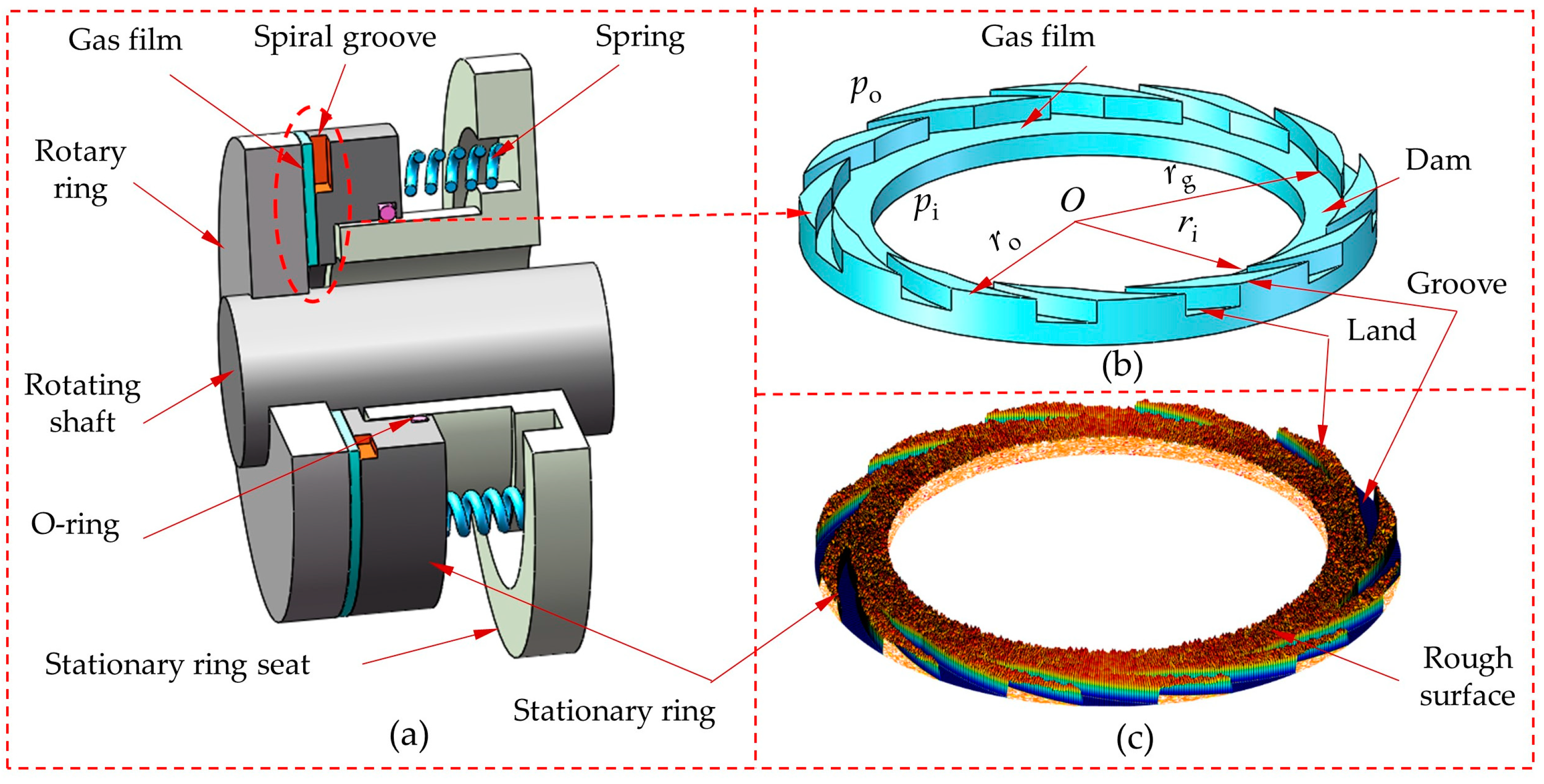
The structure of the DGS is shown in Figure 1a. It is mainly composed of a rotary ring, stationary ring, stationary ring seats, rotating shaft, flexible components (springs), auxiliary seal rings (O–rings), etc. The common combination of silicon carbide and carbon graphite was selected for the seal rings. A dynamic gas film of several micrometers is generated in the gap between the seal rings’ end faces, as shown in Figure 1b. The real contact behavior of the seal surface was the interaction between the surface asperities, as shown in Figure 1c. The contact deformation mainly occurred on the carbon graphite ring, because the hardness of silicon carbide was greater than that of carbon graphite. So GT model [12] assumes that the junction surface was equivalent to the contact between a rigid, smooth plane and a rough plane. The rotary ring with high hardness was a rigid plane, and the stationary ring with lower hardness was a rough plane.

Figure 1.
(a) The structure of DGS, (b) gas film, and (c) the microscopic surface of seal rings.
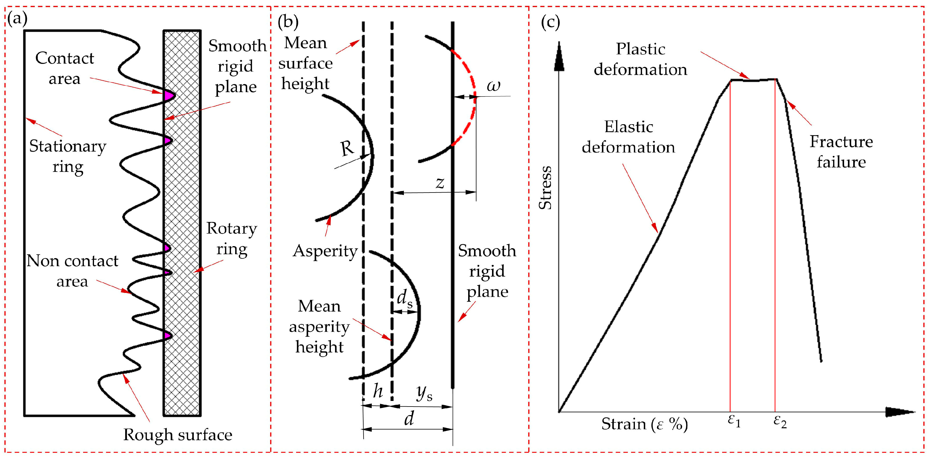
The contact diagram of seal surfaces is shown in Figure 2a. As shown in Figure 2b, the asperity peak was deformed before and after a single asperity contacted the rigid plane. In reference [13], the carbon graphite ring was loaded, and the stress–strain characteristics were obtained, as shown in Figure 2c.
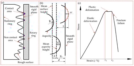
Figure 2.
(a) End face contact of DGS, (b) the asperities of seal face, and (c) stress–strain characteristics.
In Figure 2, z is the height of the asperities on the seal surface; d is the distance between the average asperity heights of the rough surface and the smooth rigid plane; h is the distance between the average surface heights of the rough surface and the smooth rigid plane; ds is the height of the rough surface contour; ys is the distance between the average asperity height of the rough surface and the average surface height line of the smooth rigid plane; R is the peak curvature radius of the asperity; and ω is the normal deformation of single asperity [14].
Characteristics were obtained, as shown in Figure 2c. The experimental results indicate that when ε < ε1, the normal stress was linearly correlated with the strain. According to Hertz elasticity theory [15], the seal ring was considered to be elastically deformed in this case. When ε1 ≤ ε ≤ ε2, the stress did not change with strain or fluctuated slightly, and plastic deformation occurred according to Abbott and Firestone plastic contact theory [16]. When ε > ε2, the stress decreased rapidly with the increase in strain. Moreover, the seal ring was subjected to apparent fracture failure.
On the basis of the experimental results of reference [13], this study assumed that the stress–strain characteristics of a single asperity on the carbon graphite ring were the same as those of the whole carbon graphite ring; that is,
where ΔL is the normal deformation of the seal ring; L is the original thickness of the seal ring; and R is the original thickness of the asperity. ω1 and ω2 are the normal deformations of elastic deformation and plastic deformation, respectively:
In the elastic contact stage, the average contact pressure Pt and contact area At of a single asperity are expressed as follows according to Hertz elasticity theory:
where E is equivalent elastic modulus. When ω2 ≥ ω ≥ ω1, the asperity was turned from the original elastic deformation into plastic deformation, and the average contact pressure Ps of a single asperity in the plastic deformation stage is
According to Abbott and Firestone [15] plastic contact theory, the contact area As is expressed as follows:
When ω > ω2, the whole asperity lost continuous deformation and experienced fracture failure along with the rapid decline of the normal stress, all of which were the characteristics of brittle materials different from metallic materials.
2.2. Actual Contact Interface Parameters of the DGS
If the asperities on the seal surface meet the Gaussian distribution, then the probability density of the asperity height distribution is expressed as follows [14]:
The number of contact asperities on the contact interface of the seal ring is
where η is the area density of asperity per unit area, and N1, N2, N3, and Nz are the number of asperities that undergo elastic deformation, plastic deformation, fracture failure, and all asperities on the seal face, respectively.
According to the actual situation of the DGS, the maximum contact force should be less than or equal to the closing force [16]. According to the calculation, the number of asperities experiencing fracture failure was less than 0.21% of the total number of asperities. Given the small number of asperities with fracture failure and complex mechanical properties, the treatment method of the microcontact characteristics of metallic materials was taken for reference [17]. During calculation, the asperities of the fracture part were assumed to experience plastic deformation; that is,
where An is the nominal contact area, then the actual contact area of the seal contact interface is
where Atr and Asr are actual contact area of asperities elastic deformation and plastic deformation, then contact force of seal face is
where Ftr and Fsr are actual contact force of asperities elastic deformation and plastic deformation.
3. Gas Film Pressure Distribution Model of the Seal Face
The actual gas film thickness of the seal face comprises the average gas film thickness h0 in the dam area and the random gas film thickness caused by the roughness of the sealing surface. In particular, the heights of the asperities on the rough surface of the seal end face follow a normal distribution, and the root mean square deviation (RMSD) of the profile is σ = 1.25Ra. The comprehensive RMSD of the seal end face is σ = (σ12 + σ22)1/2. σ is the comprehensive RMSD of the rough surface. Ra1 and Ra2 are the arithmetic mean deviations of the surface profile of the rough surface. σ1 and σ2 are the standard deviations corresponding to the rough surface. The average Reynolds equation derived by Makino et al. [18] and Xu [2] under compressible fluid condition is as follows:
where ψq is slip flow factor, which based on the F–K slid flow model [19]. ψθ and ψr are the circumferential and radial pressure flow factors, respectively. ψs is shear flow factor, and k is the gas adiabatic index, k = 1, 2 represent isothermal and adiabatic processes, respectively.
where D is the characteristic inverse Knudsen number. The expressions given are presented as follows:
where a is the surface adaptation coefficient, which is the reflection type after the collision between gas molecules and the boundary wall, generally taken as 1, and γ is the Peklenik parameter [20] and is defined as the ratio of the x– and y–half correlation lengths. The values γ = 0, 1, ∞ represent transverse, isotropic, and longitudinal roughness, respectively.
According to the geometric model shown in Figure 1, the finite difference method is used to analyze the area (the reciprocal of the number of grooves). The boundary conditions required to solve Equation (13) are as follows:
The mandatory boundary conditions are
The periodic boundary conditions are
where Ng is number of grooves.
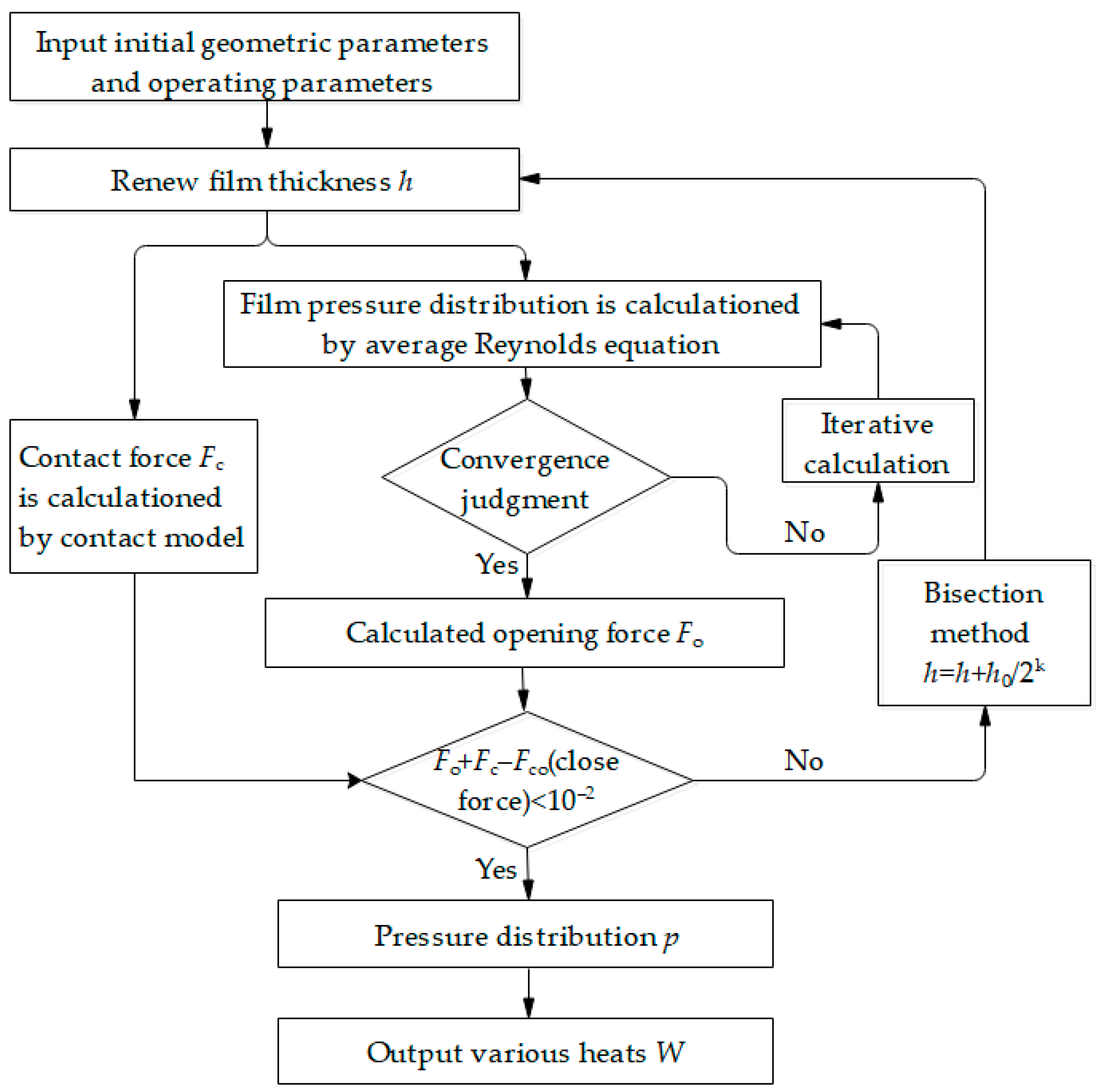
The theoretical model for the above analysis is calculated using the finite difference method based on MATLAB software. The pressure distribution of the seal ring end faces is solved in contact during the opening stage by balancing the contact force with the opening force and the closing force. In the calculation, an independence analysis was conducted to meet the required iterative accuracy and solve the average Reynolds equation. After obtaining the pressure distribution, the various heats generated are calculated. The specific calculation process is shown in Figure 3.
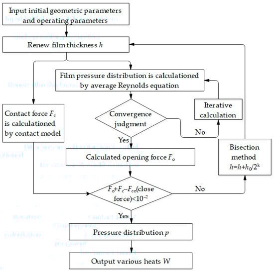
Figure 3.
Numerical calculation flowchart.
4. Heat Generation Model on the Seal Face during the Startup Process
The two seal rings of the DGS transitioned from contact to separation during the startup process, and the main heat sources on the seal face at different times were the friction heat of asperities, the viscous shear heat of the gas film, the expansion heat (heat absorbed by the gas film under adiabatic conditions), and forced convection heat transfer between the gas film and the seal ring. In the early startup process, frictional heat is mainly generated internally in the seal ring due to the contact between the seal ring end faces. As the speed increases, the seal ring end face disengages and does not contact, and the frictional heat disappears, with the remaining three types of heat being the main heat. In the study, Chen [21] from the research group considered the heat conduction equation, solved the average Reynolds equation during the stable operation process of the DGS system, analyzed the forced convection heat transfer behavior between the gas film and the seal rings, and obtained the temperature field of CO2 with impurities. This article mainly analyzes the internal heat generation during the initial startup process when the seal rings’ end faces come into contact. The external heat exchange is not obvious now and can be ignored. The results will serve as a research foundation for the next step of analyzing the four factors that affect gas film temperature during the process from startup to stable operation process and exploring the impact of heat on sealing performance.
4.1. Friction Heat Model of Asperities
The dynamic and static seal rings were in contact in the early startup process. They also maintained a certain contact pressure. In this case, the relative movement between the two rings led to the contact friction heat of the asperities. The following expression of the friction heat on the rough surface of DGS was derived from literature [22]:
where f is the solid friction coefficient of the seal face, which is obtained through experimental measurement, Mm is friction torque, and n is rotating speed.
4.2. Gas Film Shear Heat Model
When the spiral groove–type DGS started running, a gas film with an equivalent thickness of h was found between seal faces. Certain heat was generated during the sealing operation because of the friction in the gas. The friction heat in the groove platform area was calculated based on Newton’s viscous shear law, which was the sum of the heat generated in the sealing groove platform area and the heat generated in the seal dam area [23].
4.3. Gas Film Expansion Heat Model
The sealing gas pressure was generally higher than the ambient pressure. Thus, the dynamic pressure effect prompted the gas pressure to increase when the gas was flowing from the outer diameter to the inner diameter of the seal ring. Then, the gas pressure decreased rapidly at the outlet, resulting in gas depressurization and expansion. The gas needed to absorb heat because of expansion. If enough heat could not be rapidly obtained from the environment, heat could only be acquired inside the seal end face. Thus, the gas temperature declined. Polycarpou and Etsion [24] solved the flow quantity of the rough surface of the seal face. The mass leakage rate of the seal face can be acquired as follows:
where ψr is the average pressure flow coefficient; μ is the gas dynamic viscosity; Rg is the gas constant; pa is the pressure at the inner diameter of the seal ring, i.e., the ambient pressure; λa is the average free path of the gas at pa; Kn is the Knudsen number, which describes the collision of molecules during fluid motion.
The expansion heat of gas absorbing heat between two points [25] is as follows:
where Ti (i = 1, 2, …, M) is the temperature at the radial point i, k is the gas adiabatic index, and cp is the gas specific heat capacity.
According to the thermodynamic process equation, the following exists when the gas on the seal face is an ideal gas:
where pi (i = 1, 2, …, M) is the pressure at the radial point i. From Equations (24) and (25), it can be concluded that
5. Calculation Parameters Determined Experimentally
The seal ring’s surface morphology and friction coefficient are important initial conditions for the thermal analysis of DGS during the startup process. Accurate surface morphology and friction coefficient of the seal ring play an important guiding role in judging the friction heat of asperities and the gas film thickness during startup and analyzing critical disengagement conditions. In traditional studies, these two parameters are considered as initial constant values from the literature. However, the surface morphology and friction coefficient vary in the actual operation process. In particular, the friction coefficient is a function of velocity and contact pressure. In this study, these two parameters were experimentally determined.
5.1. Surface Morphology Experiment and Results
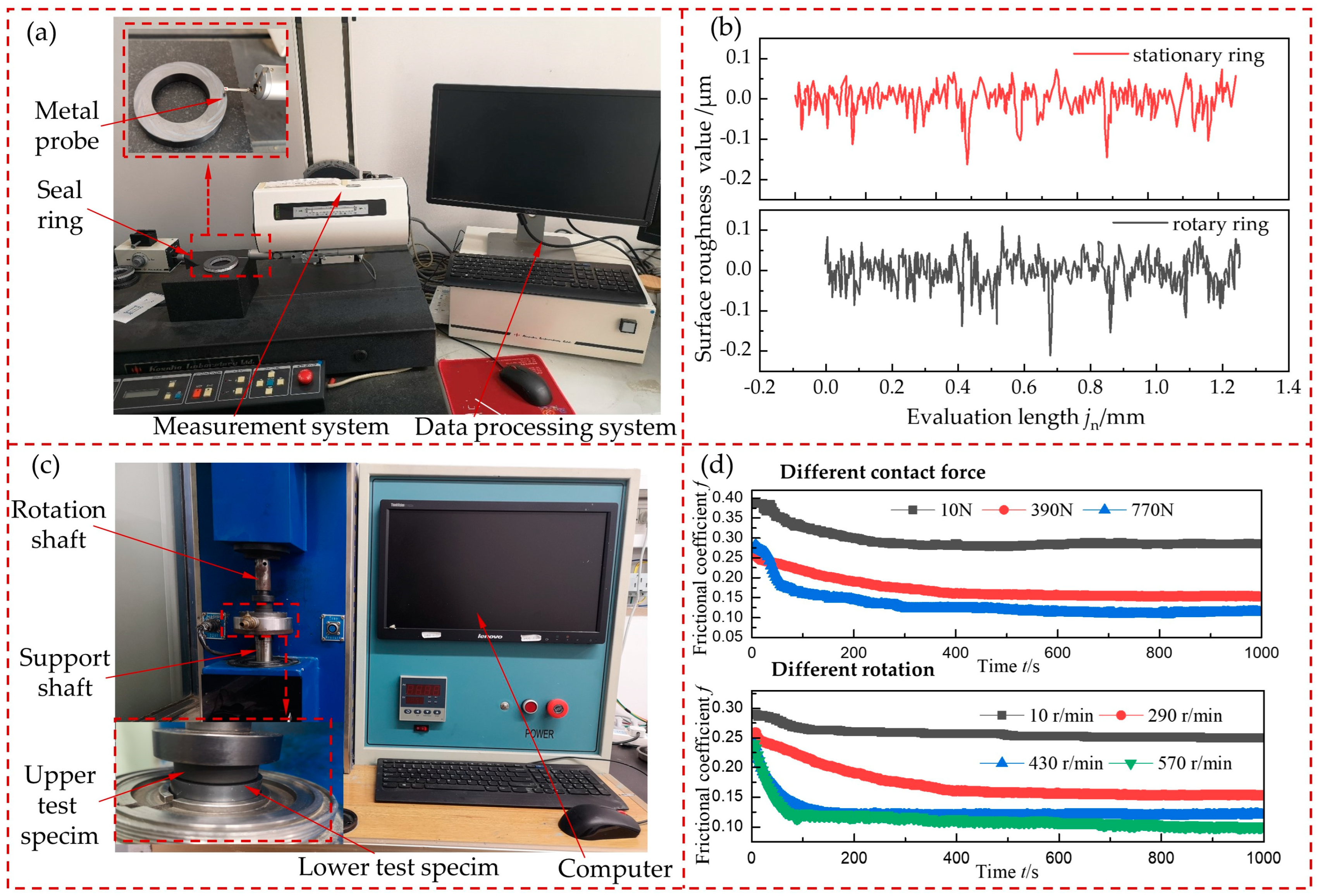
According to the theory proposed by McCool [26], the surface morphology detection principle for the rotary and stationary rings of DGS is as follows. The profile spectrum function of the rough surface was characterized by measuring the root mean square deviation (RMSD) Rq and root mean square slope difference (RMSSD) Rdq of the rough surface profile. RMSD is also commonly used to express σ. Then, the spectral moment of the profile spectrum function was solved through the surface’s profile spectrum function to solve the statistical parameters under the real morphology of the seal ring. Figure 4a is the test diagram of the surface morphology parameters of the seal ring measured by the roughness profilometer testing integrated machine. The measuring range of this machine is 0 mm to 50 mm for Z and 0 mm to 100 mm for X, the stylus radius is 2 μm, and the sampling length jr is 0.25 mm. In the experiment, the stationary ring was made of carbon graphite, and the rotary ring was made of silicon carbide. In addition, the measurement speed and evaluation length were set to 0.2 mm/s and jn = 5jr = 1.25 mm, respectively. The stationary ring has 10 positions, randomly chosen on the seal faces of the stationary and rotary rings. The average value was taken by conducting measurements at each position twice. The typical profile curves of the surface roughness of the stationary and rotary rings are displayed in Figure 4b. The measured RMSD and RMSSD of the surface profile were obtained at 10 different positions on the surfaces of the rotary and stationary rings. Absolute error was often used to evaluate measurement accuracy in multiple experimental measurements, and the formula is as follows:
where EA is absolute error, xi (i = 1, 2, …, S) is measured data on the i-th, is average of multiple measurements, and S is number of the measurements.
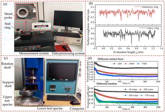
Figure 4.
Surface morphology and friction coefficient measurement: (a) experimental device of the surface profiler, (b) surface contour curve of seal rings, (c) friction and wear machine, and (d) frictional coefficient.
The average of RMSD and RMSSD experimental measurements were Rqs = 0.059, Rdqs = 0.06077, Rqr = 0.067, and Rdqr = 0.05602, and the absolute errors were EAqs = 0.0054, EAdqs = 0.0012, EAqr = 0.0042, and EAdqr = 0.000944. It can be seen that the absolute error is very small, indicating that the accuracy of the 10 measurement data was high and the values were valid. The statistical parameters of the surface morphology were calculated as follows: α = 5.646, ys = 0.085 μm, σs = 0.082 μm, R = 3.655 μm2, and η = 0.148 μm−2 [27].
5.2. Friction Coefficient Experiment and Results
The accurate characterization of the friction coefficient during the startup process affects the friction and thermal characteristics of the seal face. The friction coefficient of the silicon carbide rotary ring and carbon graphite stationary ring was measured by the friction and wear testing machine, as shown in Figure 4c. The variation laws of the friction coefficient with rotating speed and contact pressure are shown in Figure 4d. These variation laws laid the foundation for the calculation of friction heat during the startup process. The central composite experimental design was used to conduct a response surface analysis experiment on the friction coefficient with two factors and five–level values [28] by taking the friction coefficient (Y) of the sealing surface as the response value and the rotating speed (n, m/s) and contact pressure (pc, MPa) as the independent variables (five–level values were taken for each factor, coded by −2, −1, 0, 1, and 2). A total of 15 experimental groups were completed, of which 12 groups were factorial experiments and 3 groups were zero. In each group, the experiment was repeated twice, and the average value was taken. Finally, the experimental data were subjected to quadratic polynomial regression fitting via the statistical software of MINITAB to acquire the ternary quadratic regression equations of the friction coefficient with the rotating speed and contact pressure, as follows:
where pc is contact pressure.
6. Model Verification
The material characteristic parameters and geometric dimension parameters of DGS are listed in Table 1 [29,30,31]. The startup process of DGS involves many theories, such as solid friction and gas lubrication. Thus, the asperity contact model and the gas film opening force of DGS were used for respective verification. According to the analysis of the DGS friction interface contact model by Zhai [32], it can be concluded that the asperities on the surface of the stationary ring conform to elastic–plastic deformation.

Table 1.
Structure parameters and material parameters of the model.
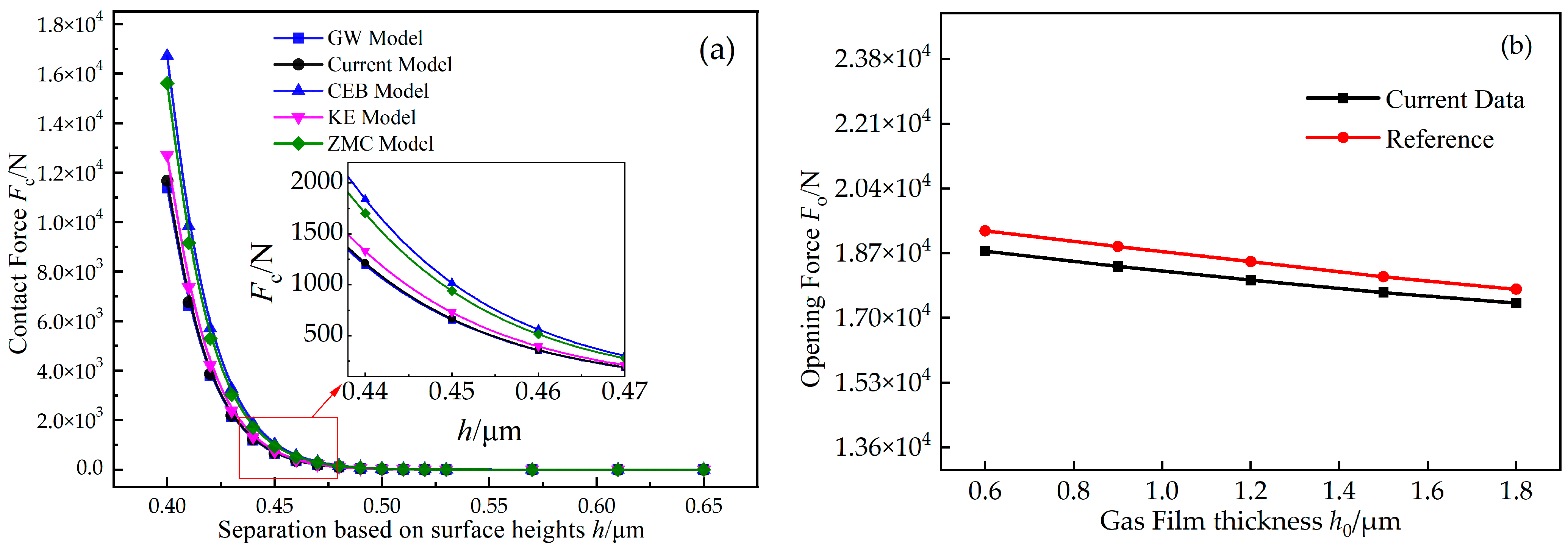
The contact force calculation result obtained through the current model was compared with the result of the classical contact models [18,33,34,35]. The variation trends of each model are displayed in Figure 5a. The results obtained in this study were consistent with the trend of each classical model and were highly approximate with the results of the GW model, which verified the conclusion of McCool [36], i.e., the GW model can accurately judge the contact characteristics of brittle materials. The working condition parameters from [2], which were chosen to verify the numerical calculation result of the average Reynolds equation, are shown in Figure 5b. The inlet pressure was 3.03 MPa, the maximum deviation of the obtained result was 2.77%, and the average deviation was 2.5%. The finite element numerical method was adopted in the literature, and the finite element difference method was used in this study. Thus, deviations resulted from the different numerical calculation methods.
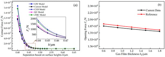
Figure 5.
(a) Contact force of different contact models and (b) verification of the average Reynolds equation.
7. Result Analysis
7.1. Influence of Gas Slip Flow Effect on Startup Thermal Effect
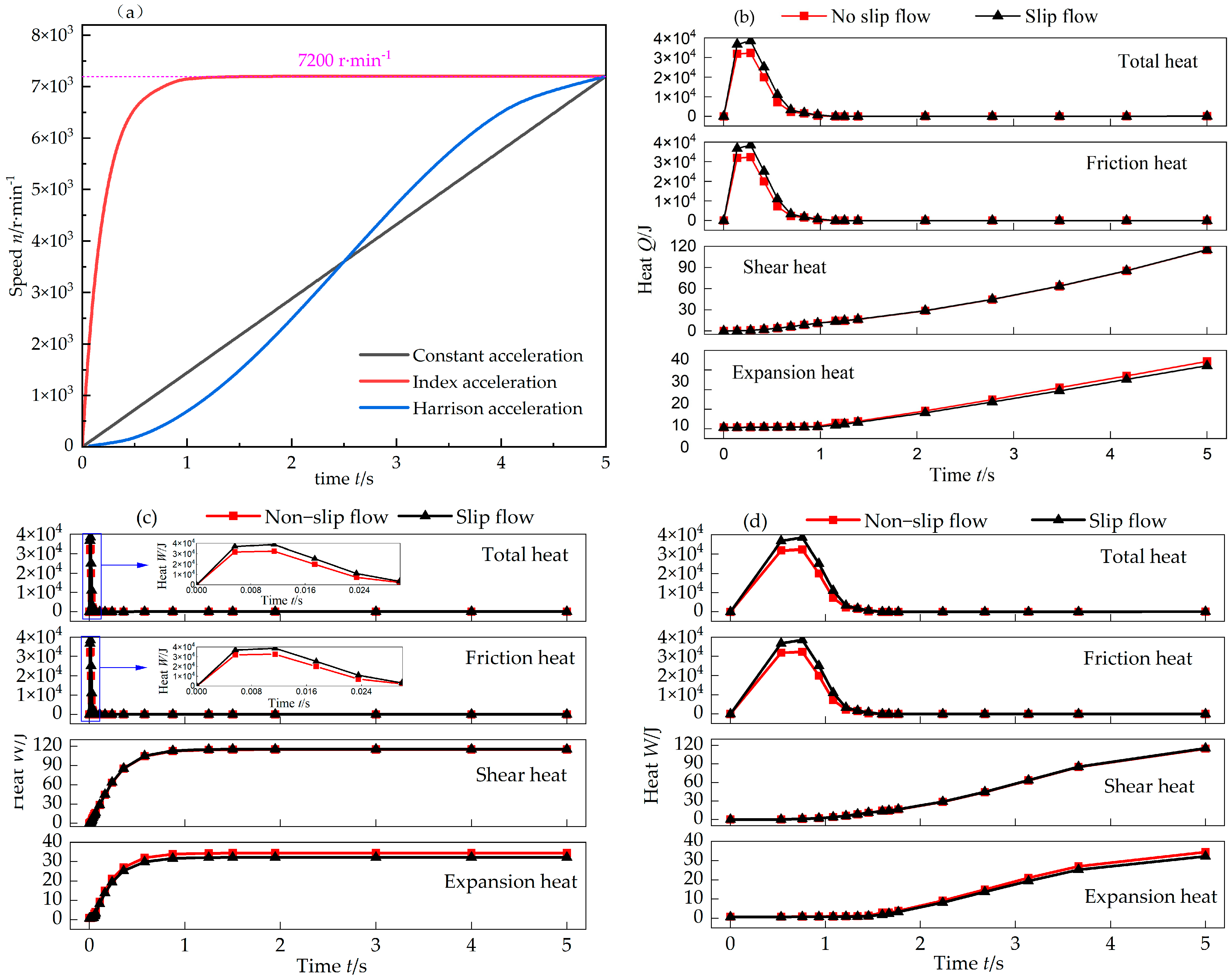
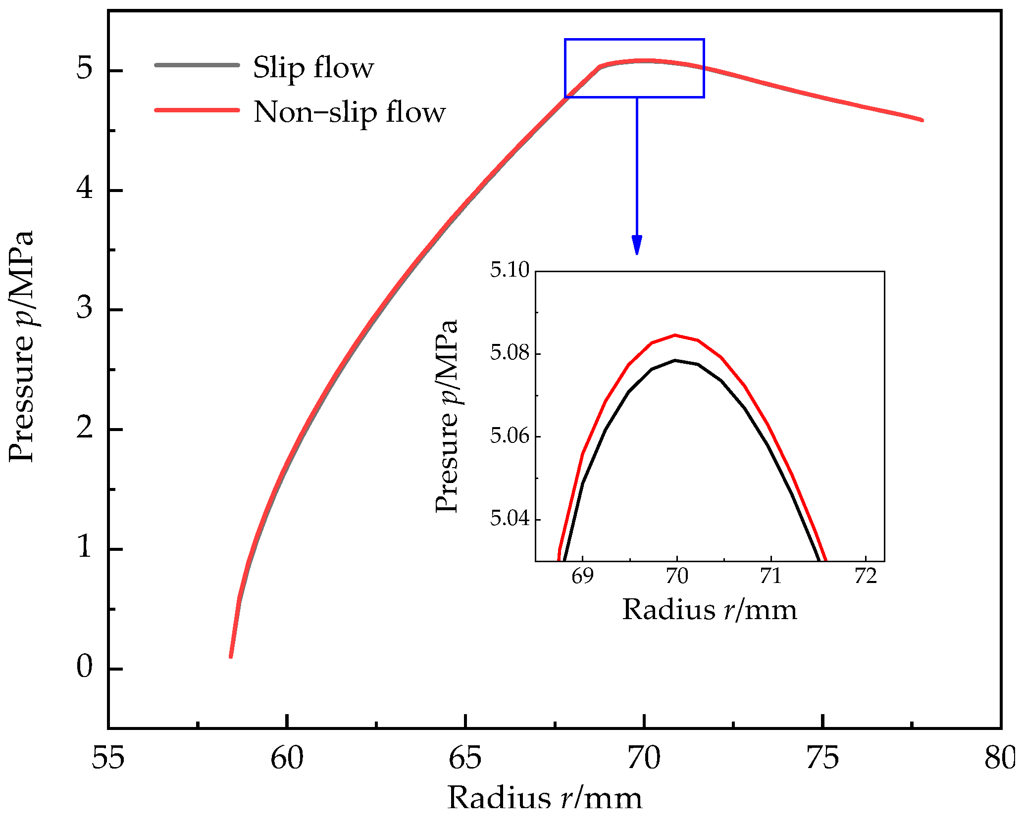
As shown in Figure 6a, three typical startup modes of DGS were chosen: constant acceleration, exponential acceleration, and Harrison acceleration. The heat generation characteristics of DGS under three different startup modes in the startup process formed by multiple time series connections (0–5 s) were analyzed. Figure 6 shows that the gas slip flow effect led to an increasing trend of total gas heat. This increasing trend occurred because when the slip flow was used as the basic calculation model, the slip flow effect was equivalent to the decrease in gas viscosity, the viscous shearing effect was weakened, and the hydrodynamic pressure effect was reduced; these phenomena decreased the gas film pressure, as shown in Figure 7. Under the constant closing force, the contact pressure of the seal face asperities was high, increasing the solid friction heat on the seal face. The heat absorbed by gas expansion was directly proportional to the leakage rate. Given the slip flow effect, the decrease in gas viscosity increased the leakage rate, resulting in an increase in the heat absorbed by gas expansion. Overall, the three startup modes showed considerable heat in the early startup process and stable heat in the later startup process. In the form of exponential acceleration, 104–magnitude heat could be reached within 1 s of startup. This scenario was extremely unfavorable to the DGS, with a risk of instability. A large amount of friction heat led to the extremely uneven heating of the seal ring, which was prone to hot cracking. The increase in heat in the Harrison acceleration mode was gentle. Moreover, the period was long, which was conducive to the heat dissipation of the sealing system. The heat generation perspective indicates that the Harrison acceleration mode is the most beneficial for sealing stability.
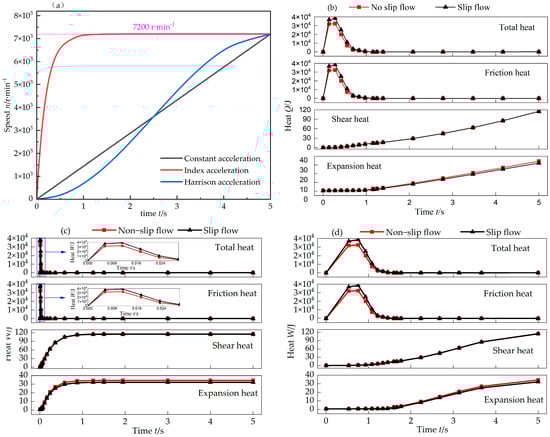
Figure 6.
Heat of different acceleration modes considering slip flow effects: (a) three acceleration methods, (b) constant acceleration, (c) index acceleration, and (d) Harrison acceleration.
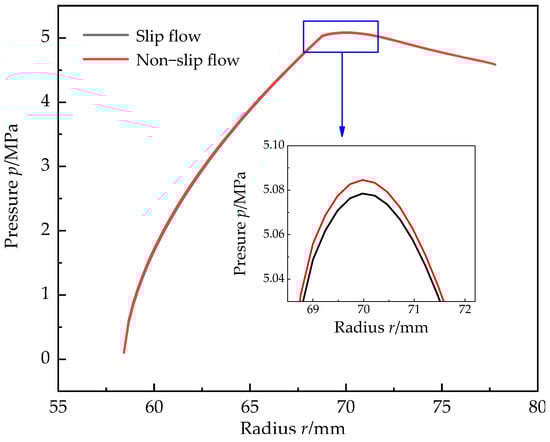
Figure 7.
The effect of slip flow on pressure distribution.
7.2. Influence of Seal Ring Surface Morphology on Startup Thermal Effect
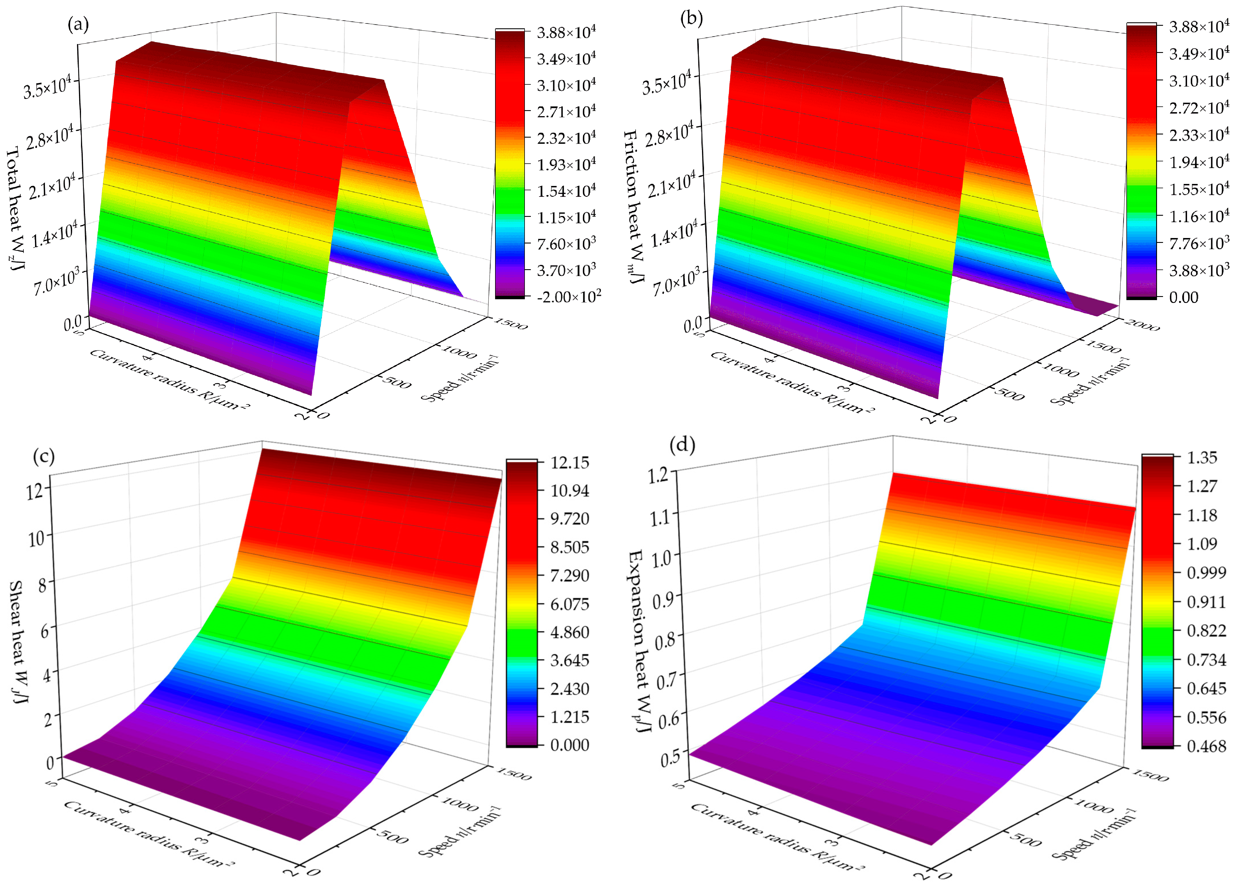
The influence of the microsurface morphology of the seal ring on the heat generation characteristics during the startup process is shown in Figure 8 and Figure 9. The surface morphology parameters of the asperities of the seal ring exerted certain influences on the startup process of DGS. In the early startup process, the morphology parameters mainly affected the friction heat generation on the seal face. In the later startup process, the morphology parameters influenced the shear heat and expansion heat of the gas film on the seal face by affecting the film thickness. The peak curvature radius of asperities is an important parameter of microsurface morphology. Figure 8 shows the influencing laws of the peak curvature radius of asperities on the heat generation characteristics of DGS during the startup process. During the whole startup process, the heat of the seal face changed obviously with the increase in the rotating speed. However, the influence of the peak curvature radius of asperities on the curvature radius of asperities would increase the seal face contact force, thereby increasing the friction heat during the startup process. When the rotating speed was 1000 r/min, the curvature radius of asperities increased from 1 μm to 5 μm, and the friction heat increased from 36,635 J to 36,800 J, with an increase of 0.45%. Moreover, the growth fluctuation was small. The reason is that an adaptive adjustment process occurred during the startup process, and the contact force could be adjusted by adjusting the film thickness. The shear heat and expansion heat of the gas film were not obvious in the early startup process. Thus, the total heat was mainly the friction heat of asperities. The analysis indicated that the influence trend of the area density of asperities on the seal face heat during the startup process was the same as the peak curvature radius of asperities. Therefore, it is not detailed in the present study.

Figure 8.
The influence of curvature radius on heat: (a) total heat, (b) friction heat, (c) shear heat, and (d) expansion heat.
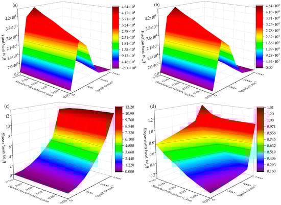
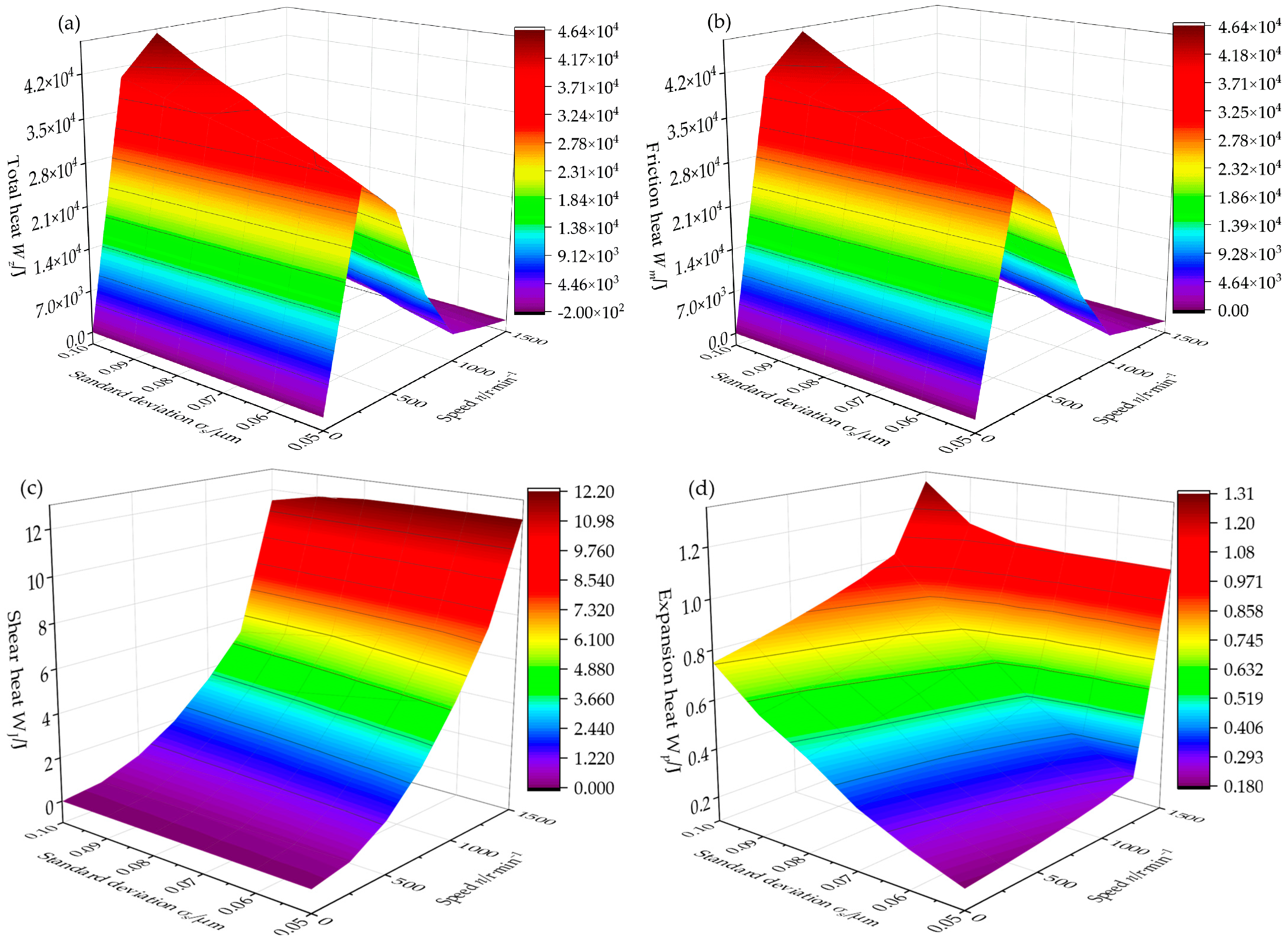
Figure 9.
The influence of standard deviation on heat: (a) total heat, (b) friction heat, (c) shear heat, and (d) expansion heat.
Figure 9 shows the height distribution of asperities on the seal surface during the startup process of DGS and the influence of the standard deviation on thermal characteristics. The total heat and friction heat of the seal face first increased and then decreased with the increase in the rotating speed. Then, they increased with the increase in the standard deviation of the height distribution of asperities on the surface. The standard deviation of the height distribution of asperities could reflect the roughness of the seal face: The greater the standard deviation of the asperity height distribution, the greater the roughness, the fluctuation of the seal face’s roughness peak, and the friction resistance. This scenario led to an increase in heat. The shear heat of the gas film increased with the increase in the rotating speed and decreased with the increase in the standard deviation of the surface asperities’ height distribution, because the increase in roughness increased the peak–valley difference and the equivalent film thickness but weakened the intermolecular interaction, resulting in the decrease in shear heat. The expansion heat of the gas film on the end face increased with the increase in the rotating speed and the standard deviation of the surface asperities’ height distribution because the increase in the equivalent gas film thickness prompted the increase in the leakage. The work of gas expansion was directly proportional to the leakage rate, thereby increasing the gas expansion heat.
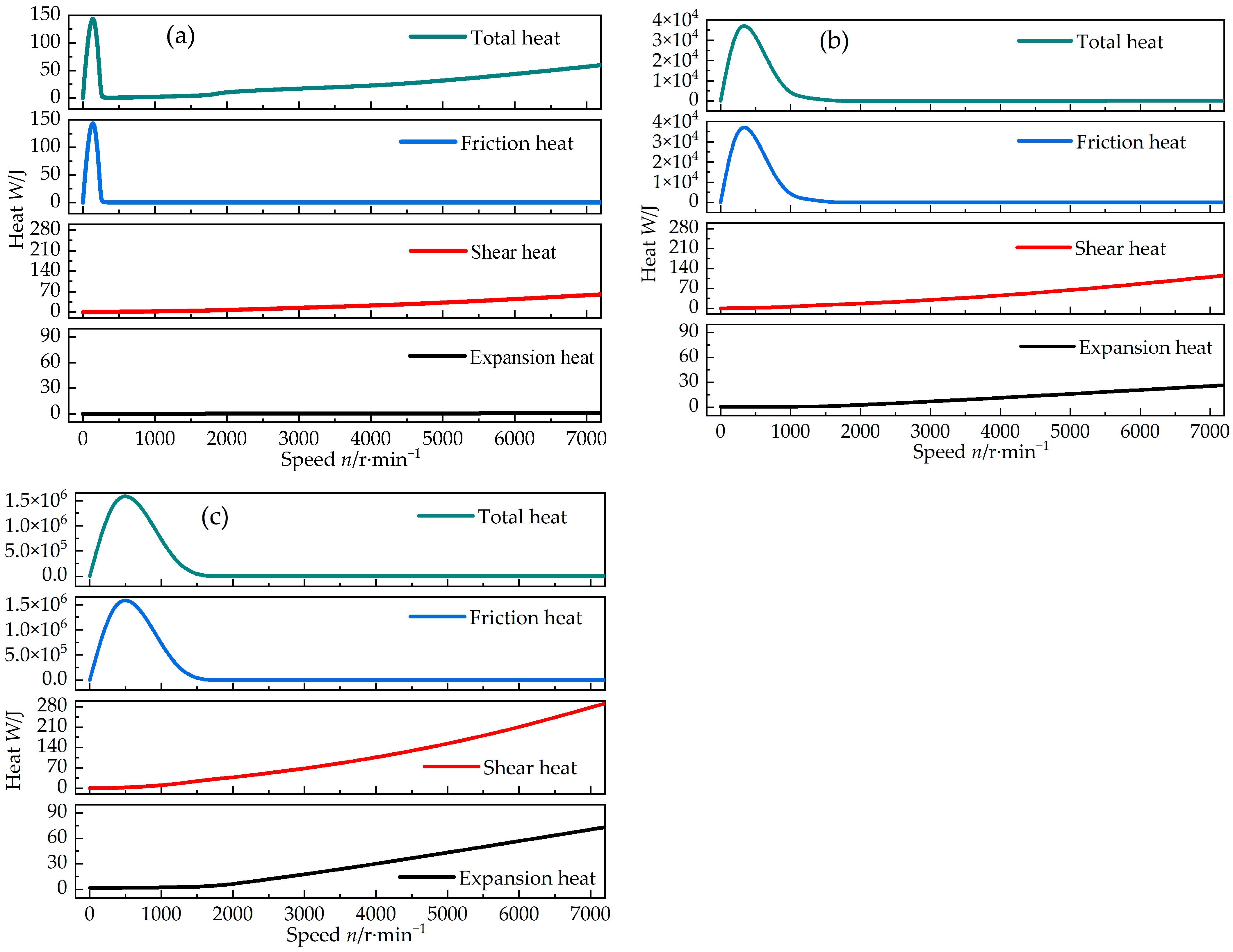
7.3. Influence of Working Pressure on Startup Thermal Effect
The changes in the heat characteristics on the seal face during the startup process are shown in Figure 10. During the whole startup process, the seal face heat initially increased sharply, then declined rapidly, and finally increased slowly. The heat in the early stage rapidly increased because the seal face was not disengaged in the early startup process, and friction occurred between the asperities on the seal face, resulting in considerable friction heat. However, the dynamic pressure effect of the seal face was enhanced, and the film thickness gradually increased with the increase in the rotating speed. Moreover, the seal face was disengaged, and the friction heat no longer existed. The increase in heat during the later startup process entirely resulted from the interaction between shear heat and expansion heat of the gas film. The friction heat generated by the seal face asperities in the early startup process was particularly obvious with the increase in the working pressure. The friction heat of the asperities reached 1.6 × 10⁶ J when the working pressure reached 10 MPa. With the increased working pressure, the friction heat of the seal face asperities lasts long. This scenario had a negative impact on the stable operation of DGS and even led to the hot cracking of the seal ring, leading to seal failure. The shear heat and expansion heat of the gas film were much smaller than the friction heat of asperities. However, no linear relations were found. The shear heat and expansion heat of the gas film presented an increasing trend because the rotating speed was accelerated in the startup process. However, the shear heat of the gas film was an exothermic process, whereas the expansion heat was an endothermic process, reaching an offset effect. Overall, the seal face heat during the startup process was always under a net growth state and increased with the acceleration of the rotating speed.
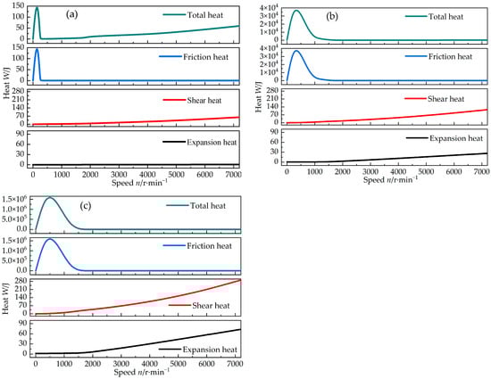
Figure 10.
Thermal characteristics under different working pressures: (a) operating pressure Po = 0.303 MPa, (b) operating pressure Po = 4.5852 MPa, and (c) operating pressure Po = 10 MPa.
8. Conclusions
The stable operation of DGS is affected by the complicated heat generation characteristics in the startup process. In this study, the statistically modified contact model and the average Reynolds equation were combined by considering the adiabatic index of the DGS system to explore the heat generation characteristics. The change laws and influencing factors, such as the friction heat of asperities and the shear heat and expansion heat of the gas film and total heat, were also analyzed. Finally, the following conclusions were drawn:
- The friction heat of DGS is much greater than the expansion heat and shear heat of gas during the startup process. However, the time course of friction heat is short and mainly concentrated in the early startup process. It disappears rapidly with the increase in the rotating speed. However, the shear heat and expansion heat of the gas film on the seal face last long.
- The heat generated by the shear heat of the gas film is greater than the heat absorbed by the expansion heat in the later startup process. The heat of the whole seal face continues to increase with the increase in the rotating speed. In this case, the heat mainly comes from the shear heat of the gas film. The slip flow effect of gas film leads to an increase in heat during the startup process.
- Despite constant acceleration, exponential acceleration, or Harrison acceleration modes, the heat changes are uneven during the startup process. In particular, the heat changes rapidly in the early stage and slowly in the later stage. The Harrison acceleration mode is the most conducive to sealing stability.
- The startup process involves various transient characteristics (including mechanical characteristics and heat generation characteristics of the seal face, thermal deformation characteristics of the seal ring, and heat transfer characteristics of the seal ring and sealing cavity). The follow–up research will focus on coupling various factors to study comprehensively the non–steady performance of DGS during the startup process.
- The research results are limited to the parameters of operating conditions and the combination of a carbon graphite material stationary ring and a silicon carbide rotary ring. If the geometric and working parameters of the model are changed, this conclusion still needs further exploration.
Author Contributions
Conceptualization, H.X. and X.S.; methodology, Q.D.; software, Q.D. and W.M; validation, Q.D., X.S., and H.X.; formal analysis, Q.D.; investigation, H.X. and X.S.; data curation, Q.D.; and X.S.; writing—original draft preparation, Q.D.; writing—review and editing, Q.D. and X.S.; visualization, W.M.; supervision, W.M.; project administration, H.X; funding acquisition, H.X. All authors have read and agreed to the published version of the manuscript.
Funding
This research was funded by Special Youth Fundamental Research of Yunnan Province (Grant No. 202101AU070019) and the Talent Training Project of Kunming University of Technology (Grant No. KKZ3202005059).
Data Availability Statement
The datasets used or analyzed during the current study are available from the corresponding author upon reasonable request.
Conflicts of Interest
The authors declare no conflict of interest.
References
- Su, H.; Rahmani, R.; Rahnejat, H. Thermohydrodynamics of bidirectional groove dry gas seals with slip flow. Int. J. Therm. Sci. 2016, 110, 270–284. [Google Scholar] [CrossRef]
- Xu, J.; Peng, X.; Bai, X.; Li, J.; Wang, Y. Effects of surface micro-scale and thermal viscosity on sealing performance of spiral–grooved dry gas seal. CIESC J. 2013, 64, 3291–3300. [Google Scholar]
- Salant, R.F.; Cao, B. Unsteady analysis of a mechanical seal using Duhamel’s method. J. Tribol. 2005, 127, 623–631. [Google Scholar] [CrossRef]
- Brunetière, N.; Thomas, S.; Tournerie, B. The parameters influencing high-pressure mechanical gas face seal behavior in static operation. Tribol. Trans. 2009, 52, 643–654. [Google Scholar] [CrossRef]
- Fairuz, Z.M.; Jahn, I.; Rahman, R.A. The effect of convection area on the deformation of dry gas seal operating with supercritical CO2. Tribol. Int. 2019, 137, 349–365. [Google Scholar] [CrossRef]
- Ma, C.; Bai, S.; Peng, X. Thermoelastohydrodynamic characteristics of T-grooves gas face seals. Int. J. Heat Mass Transf. 2016, 102, 277–286. [Google Scholar] [CrossRef]
- Liu, Y.; Liu, W.; Li, Y.; Liu, X.; Wang, Y. Mechanism of a wavy-tilt-dam mechanical seal under different working conditions. Tribol. Int. 2015, 90, 43–54. [Google Scholar] [CrossRef]
- Meng, X.; Peng, X.; Wang, L. Axisymmetric dynamic model and seal behavior analysis of mechanical seals during startup and shutdown operation. CIESC J. 2011, 62, 1620–1625. [Google Scholar]
- Xu, L. Transient Dynamic Characteristics of Upstream Pumping Mechanical Seal. Master’s Thesis, China University of Petroleum (East China), Qingdao, China, 2018. [Google Scholar]
- Xu, L.; Hao, M.; Yuan, X.; Wang, Y.; Jin, Y.; Li, Y. Dynamic analysis for vibration and impact of liquid film sealing. J. Vib. Shock 2020, 39, 58–65. [Google Scholar]
- Xu, L.; Wand, Y.; Zhang, F.; Hao, M.; Yuan, X. Lubrication characteristics of spiral mechanical seals during transient start-up. China Mech. Eng. 2020, 31, 1891–1900. [Google Scholar]
- Greenwood, J.A.; Tripp, J.H. The contact of two nominally flat rough surfaces. Proc. Inst. Mech. Eng. 1970, 185, 625–634. [Google Scholar] [CrossRef]
- Dong, M.; Gong, J.; Lyu, J.; Dong, G. Tribology design of sealing materials using plastic index. Surf. Technol. 2017, 45, 180–185. [Google Scholar]
- Greenwood, J.A.; Williamson, J.B.P. Contact of nominally flat surfaces. Proc. R. Soc. Lond. Ser. A Math. Phys. Sci. 1966, 295, 300–319. [Google Scholar]
- Johnson, K.L. Contact Mechanics, 1st ed.; Cambridge University Press: Cambridge, UK, 1985; pp. 84–106. [Google Scholar]
- Fan, Y.; Song, P.; Xu, H. Study on startup operation of dry gas seal with steam lubrication. CIESC J. 2020, 71, 3671–3680. [Google Scholar]
- Abbott, E.; Firestone, F. Specifying surface quality: A method based on accurate measurement and comparison. Mech. Eng. 1933, 107, 569–572. [Google Scholar]
- Makino, T.; Morohoshi, S.; Taniguchi, S. Application of average flow model to thin film gas lubrication. J. Tribol. 1993, 115, 185–190. [Google Scholar] [CrossRef]
- Deng, Q.; Song, P.; Xu, H.; Mao, W.; Sun, X. Analysis Analysis on the startup characteristics of CO dry gas seal based on the F-K slip flow model at high pressure. Adv. Mech. Eng. 2023, 15, 1–13. [Google Scholar] [CrossRef]
- Peklenik, J. New Developments in surface characterization and measurements by means of random process analysis. Proc. Inst. Mech. Eng. 1967, 182, 108–126. [Google Scholar] [CrossRef]
- Chen, W.; Song, P.; Xu, H.; Sun, X. Calculation of physical parameters and analysis of temperature fields of CO2 with Impurities dry gas seal at operating points. Adv. Eng. Sci. 2023, 55, 265–278. [Google Scholar]
- Song, X. Analysis and Solution of Friction Heat in Mechanical Seals. Sci. Technol. Enterp. 2013, 4, 271–273. [Google Scholar]
- Chan, W.; Song, P. Research on heat equilibrium film thickness of spiral groove dry gas seal. Lubr. Eng. 2015, 40, 5–8. [Google Scholar]
- Polycarpou, A.A.; Etsion, I. Static sealing performance of gas mechanical seals including surface roughness and rarefaction effects. ASME J. Tribol. 1998, 41, 531–536. [Google Scholar] [CrossRef]
- Zhu, M.; Liu, Y.; Lin, Z.; Peng, X. Engineering Thermodynamics, 2nd ed.; Tsinghua University Press: Beijing, China, 2011; pp. 22–23. [Google Scholar]
- McCool, J.I. Relating profile instrument measurements to the functional performance of rough surfaces. J. Tribol. 1987, 109, 264–270. [Google Scholar] [CrossRef]
- Sun, X.; Song, P.; Mao, W.; Deng, Q.; Xu, H.; Chen, W. Dynamic contact analysis of dry gas seal during start-stop process considering material properties and surface topography of seal rings. CIESC J. 2021, 72, 4279–4291. [Google Scholar]
- Peng, L.; Gao, X.; Chen, K. Catalytic upgrading of renewable furfuryl alcohol to alkyl levulinates using AlCl3 as a facile, efficient, and reusable catalyst. Fuel 2015, 160, 123–131. [Google Scholar] [CrossRef]
- Gabriel, R.P. Fundamentals of spiral groove noncontacting face seals. Lubr. Eng. 1994, 50, 215–224. [Google Scholar]
- Hu, Q.; Sun, J.; Ma, C.B.; Yu, B. Theoretical prediction of mixed frictional heat of mechanical seals based on shoulder-shoulder contact model of asperities. J. Mech. Eng. 2017, 53, 102–108. [Google Scholar] [CrossRef]
- Itzhak, G. A Transient Dynamic Analysis of Mechanical Seals Including Asperity Contact and Face Deformation. Tribol. Trans. 2002, 45, 284–293. [Google Scholar]
- Zhai, X.; Yang, X.; Chen, J. Elastic-plastic contact stiffness model of dry gas seal friction interface. J. Vib. Shock 2023, 42, 165–171. [Google Scholar]
- Chang, W.R.; Etsion, I.; Bogy, D.B. An elastic–plastic model for the contact of rough surfaces. Trans. ASME J. Tribol. 1987, 109, 257–263. [Google Scholar] [CrossRef]
- Kogut, L.; Etsion, I. Elastic-plastic contact analysis of a sphere and a rigid flat. J. Appl. Mech. 2002, 69, 657–662. [Google Scholar] [CrossRef]
- Zhao, Y.; Maietta, D.M.; Chang, L. An asperity microcontact model incorporating the transition from elastic deformation to fully plastic flow. J. Tribol. 2000, 122, 86–93. [Google Scholar] [CrossRef]
- McCool, J.I. Comparison of models for the contact of rough surfaces. Wear 1986, 107, 37–60. [Google Scholar] [CrossRef]
Disclaimer/Publisher’s Note: The statements, opinions and data contained in all publications are solely those of the individual author(s) and contributor(s) and not of MDPI and/or the editor(s). MDPI and/or the editor(s) disclaim responsibility for any injury to people or property resulting from any ideas, methods, instructions or products referred to in the content. |
© 2023 by the authors. Licensee MDPI, Basel, Switzerland. This article is an open access article distributed under the terms and conditions of the Creative Commons Attribution (CC BY) license (https://creativecommons.org/licenses/by/4.0/).