Abstract
To enhance the efficiency of automotive engines, a comprehensive understanding of friction generation within their components is paramount. Moreover, extensive global research efforts have been dedicated to nanoparticles, leading to the emergence of nanolubricants. In this study, an investigation was conducted focused on the piston ring–cylinder tribological interaction using fullerenes as additives. This is a very important issue since the friction forces can be significantly reduced. In order to solve this problem, a 2D CFD approach was implemented, taking into account a roughness model and temperature variations. The obtained results clearly show a friction reduction using fullerenes as additives compared to both synthetic and monograde oils. Furthermore, using fullerene oils, the performance of the compression piston ring system is improved due to friction reduction and the change of the temperature distribution. This study is beyond SOTA, since there is a limited contribution in the field of such nanolubricants in compression piston ring system. It is evident that the friction force is reduced by 42% compared to synthetic oils, showing a perspective on more tribologically efficient internal combustion engines.
1. Introduction
The pursuit of enhanced engine efficiency has driven a reduction in lubricating oil viscosity, aimed at minimizing losses within hydrodynamic lubrication mechanisms. This approach has, in turn, elevated the significance of piston ring and cylinder bore systems in managing mixed and boundary lubrication scenarios. To optimize friction efficiency in these lubrication regimes, one strategy involves the application of friction modifiers [1,2]. The reduction in oil viscosity is achieved through the inclusion of antiwear additives, such as zinc dialkyldithiophosphate (ZDDP).
Synthetic lubricants frequently incorporate nanoparticles as additives, which come in varying dimensions, forms, and volume ratios. In numerous applications in tribology, lubricants enhanced with nanoparticles have demonstrated superior performance in terms of reducing friction and wear. This improvement can be attributed to their exceptional dispersion properties, enhanced lubricating characteristics, and improved thermal conductivity. Consequently, gaining a comprehensive understanding of nanoparticle behavior is imperative for advancing mechanisms of lubrication, which, in turn, can aid in meeting stringent regulations governing vehicle emissions. [1] underscored the increasing significance of the creation of a tribofilm initiated by friction modifiers and antiwear additives at the contact interface. This effect proves especially advantageous in mitigating frictional losses and reducing energy consumption, particularly in the realm of transportation. Notably, these advantages become most apparent in situations where the oil film is limited, as in mixed and boundary lubrication scenarios [2]. To attain reduced friction and wear in various mechanical interactions, a variety of nanoparticle types, typically ranging from 1 to 120 nanometers in size, are introduced into diverse lubricants.
For instance, Lee et al. [3] conducted experiments involving fullerene nanoparticles with a disk-on-disk tester, demonstrating that synthetic lubricants led to a substantial 90% reduction in friction in comparison to the commercial oil. Similarly, Padgurskas et al. [4] explored the impact of iron (Fe), copper (Cu), and cobalt (Co) nanoparticles, along with their compounds, in a synthetic oil. Their research highlighted that Cu nanoparticles outperformed the others, leading to a significant reduction in both friction and wear. In another investigation, Wan et al. [5] delved into the qualities of lubricating oil containing boron nitride nanoparticles. They examined various nanoparticle concentrations in a synthetic oil (SAE 15W40) and determined that the optimal combination of particle size and concentration was 120 nanometers and 0.1 wt%, respectively. This optimal formulation resulted in a substantial 77% reduction in friction compared to the base oil. These findings collectively underscore the promising prospects of nanoparticles in enhancing tribological performance.
Zavos et al. [6] and Morris et al. [7] have exhibited significant progress by including the thermal effect of the ring-lined conjugate surface conditions and pressure in the cylinder deterioration. These papers illustrate that the friction mechanism is significantly impacted by factors such as the surfaces of the ring and cylinder, as well as the flow conditions and minimum thickness of lubricant’s film. Additionally, the flow of lubricant within the ring–liner junction demonstrates a heightened level of complexity. Shahmohamadi et al. [8] conducted computational fluid dynamics (CFD) simulations, considering the impact of cavitation on frictional forces, the lubricant’s film, and the surrounding temperature. They developed a comprehensive thermal mixed lubrication model, demonstrating that cavitation flows significantly influence the resilience of the system at elevated engine speeds. Bewscher et al. [9] additionally noted that the occurrence of oil contact depletion may results from regurgitation and absence of oil. They found out that the effect of the above is an increase in friction and a thinning of the lubricating film. Regarding the slender design of the piston ring, various analytical and experimental studies have been conducted to investigate the tribological performance of the piston ring under various engine operating conditions. Rahmani et al. [10] and Baker et al. [11] introduced a numerical prediction and experimental measurement approach for analyzing the piston ring–liner interaction. Their findings indicated that under hot engine conditions, elastodynamics in thin rings resulted in thinner lubricant films and increased friction values.
Hence, the engine lubricants currently employed in internal combustion engines (ICEs) play a vital role in reducing frictional losses and minimizing wear at contact points. As a result, the predominant research focus has centered on assessing how engine oil viscosity and the effects of aging influence the performance of passenger cars, as mentioned in [10]. Furthermore, various methodologies have been proposed and explored in the existing literature to investigate alterations in lubricating oil viscosity and its degradation over time. For instance, Besser et al. [12] observed that the formulation of the oil significantly influenced key engine oil parameters like oxidation and aging processes. Sikora and Miszczak [13] conducted experimental research, which included an analysis of viscosity and changes in the lubricant employed in two harbor tugs named HEROS, both equipped with Caterpillar CAT3516DITA engines and subjected to similar operating hours. The lubricant in question was produced by Fuchs Oil Corporation, meeting SAE 15W-40 specifications. They conducted viscosity measurements across a temperature range of −10 to 120 °C and emphasized that the aging of mineral oil has a profound influence on the tribological performance of journal bearings. Furthermore, Dam et al. [14] conducted an investigation into how the aging history of lubricant influenced emission levels. In their study, a 12.7 L heavy-duty diesel engine underwent testing on an engine test stand for 40 h while SAE 15W-40 oil was used. Their findings indicated that oil aging had limited effects on gas and mass emissions as well as the metal content in exhaust gases.
In recent years, numerous tribologists, [6,10,11], have developed advanced models to elucidate the fundamental lubrication mechanisms occurring in the piston ring assembly. These models have become increasingly important due to the dynamic nature of engine operation, where rapid changes in loads and engine velocity give rise to varying contact conditions. The primary lubrication stages encountered during the reciprocation of the piston ring assembly, from top dead center to bottom dead center, include the boundary/mixed and hydrodynamic regimes.
Hence, the friction generated within the ring is notably influenced by both Poiseuille shear and the direct contact of surface asperities. In such scenarios, lubricants fortified with nanoparticles play a crucial role in safeguarding the contacting surfaces, effectively reducing wear and enhancing oil stability.
Within the context of this study, a 2D computational fluid dynamics (CFD) model was developed, which is grounded in the Navier–Stokes equation and vapor transport principles and employs a Lagrangian approach for tracking nanoparticle motion. Here are the key configurations that were incorporated:
- Piston ring selection: A piston ring was selected, sourced from a motorbike engine as our subject of study. This ring features an ideal parabolic profile.
- Flow characteristics: The flow within our model is characterized as laminar, and we accounted for variations in lubricant properties based on changes in both temperature and pressure within the contact interface.
- Two-phase flow: A two-phase flow was integrated aspect using the vapor transport approach, specifically applying the Rayleigh–Plesset equation.
- Nanoparticle behavior: To comprehensively address nanoparticle behavior, we employed a Lagrangian method. This method allowed us to solve equations for individual nanoparticles, tracking their movement throughout the lubricant field.
- Asperity load consideration: Under mixed lubrication conditions, we accounted for the load exerted by surface asperities using the stochastic model developed by Greenwood and Tripp [15].
These configurations collectively form the foundation of our 2D CFD model, enabling us to investigate and better understand the complex dynamics of the piston ring assembly and lubrication processes.
The novelty of this paper is the implementation of a full simulation model, including a surface roughness (according to Greenwood and Tripp [15]) model and temperature effects, comparing under these regimes the tribological behavior of a synthetic oil (SAE10W30), a monograde oil (SAE30), and the lubricant using fullerenes as additives. Also, the investigation of the fullerenes particles trajectories and the examination of the hot and cold operational conditions drives this study beyond SOTA. All the above leads to a complete study of the tribological performance of internal combustion engines lubricated with fullerene oil.
This paper’s key highlights revolve around three main aspects. Firstly, it undertakes a comparative evaluation of SAE 10W30, SAE30, and fullerene-based oils, assessing their behavior under uniform thermal conditions. Secondly, the research conducts an extensive comparison of the viscous friction characteristics exhibited by these lubricants, accounting for both thermal parameters and surface roughness. Lastly, the paper offers an in-depth analysis of nanoparticle trajectories within the lubrication system, shedding light on their motion patterns and interactions with the lubricant flow. These findings collectively enhance our understanding of lubricant performance, making significant contributions to the field.
All in all, the novelty of this paper is the implementation of a full simulation model including a surface roughness (according to Greenwood and Tripp) model and temperature effects. Also, the investigation of the fullerenes particles’ trajectories and the examination of the hot and cold operational conditions drives this study beyond SOTA.
The paper is structured as follows: It begins with an ‘Abstract,’ providing a succinct analysis of the research, including the methods employed and the obtained results. The ‘Introduction’ section follows, offering a literature review and outlining the innovative contributions of the research. ‘Theory and Modelling’ is where the theoretical foundations and modeling techniques, particularly the mathematical equations governing the piston ring–cylinder problem, are discussed. Moving on, the ‘Analysis of Nanoparticles’ Motion’ section addresses the governing equations pertaining to nanoparticle kinematics, elucidating their role in enhancing lubricant performance. ‘Results of Thermal Analysis’ presents findings comparing synthetic SAE 10W30 lubricant with fullerene-based lubricant, along with considerations for rough surface asperities and their contrast with smooth surface models under thermal effects. Finally, in the ‘Conclusions’ section, the paper thoroughly discusses the results and calculates percentage differentials, offering a comprehensive summary of the research’s key insights.
2. Materials and Methods
A 2D CFD model was constructed using Ansys FLUENT to address a nonlinear flow problem with coupled governing equations. Our selected approach utilized the pressure-based mixture model, with velocity–pressure coupling being controlled through the Semi-Implicit Method for Pressure-Linked Equations (SIMPLE) algorithm. The utilization of the SIMPLE algorithm was crucial for reducing discretization-induced errors, employing a second-order upwind configuration. To ensure robust and accurate results, grid sensitivity tests were conducted to determine the optimal mesh requirements. The model encompassed a total of 31,031 quadrilateral volumes, providing a comprehensive representation of the simulated system. In terms of time integration, a time step of 10−3 s was employed to stabilize the flow during the simulation. Furthermore, a convergence criterion of 10−5 was adopted to gauge the convergence of the simulation results effectively. To account for viscosity, the power-law model, as presented by Zavos and Nikolakopoulos [16], was implemented. In summary, this well-structured CFD model, based on Ansys FLUENT, employed advanced techniques and rigorous numerical methods to address complex fluid flow phenomena in a nonlinear context, providing reliable and accurate results for the study.
The motion of the ring corresponded to the piston’s sliding velocity along the inner cylinder liner. This velocity is determined using the following calculation (1):
where the following definitions apply:
- ‘r’ is the crank-pin radius;
- ‘ω’ is the engine’s rotational speed;
- ‘φ’ represents the crankshaft angle;
- ‘λCR’ signifies the control ratio.
It is important to note that in this context, we have not accounted for ring twist. The approximation of the thickness of the lubricant’s film between the piston ring and the cylinder liner can be expressed as below:
In this analysis, we define the following parameters:
- ‘h(t)_min’: minimum lubricant film thickness.
- ‘hs(x)’: the parabolic ring profile .
- ‘δ’: localized deflection induced by contact pressure.
It is important to note that ‘δ’ has a limited impact on this analysis. While previous references [6,17] have described the ring profile as having a pronounced axially asymmetric shape, this investigation simplifies it to an idealized parabolic ring shape. Additionally, it has been assumed the cylinder liner retains a flawless circular form. The primary focus of this study is on the utilization of synthetic engine oil with fullerene additives. Consequently, it does not delve into the effects of variations in the contact profile of the ring or the geometry of the cylinder’s bore. For this analysis, it is established that the latter parameter has a minimal impact on the ring-to-liner contact. As suggested in [18], localized ring deformation becomes more critical when higher combustion pressures are anticipated. However, within the scope of this analysis, localized ring deformation is found to have a minor effect on the distribution of the lubricant film. Specifically, this factor becomes more critical when anticipating elevated combustion pressures.
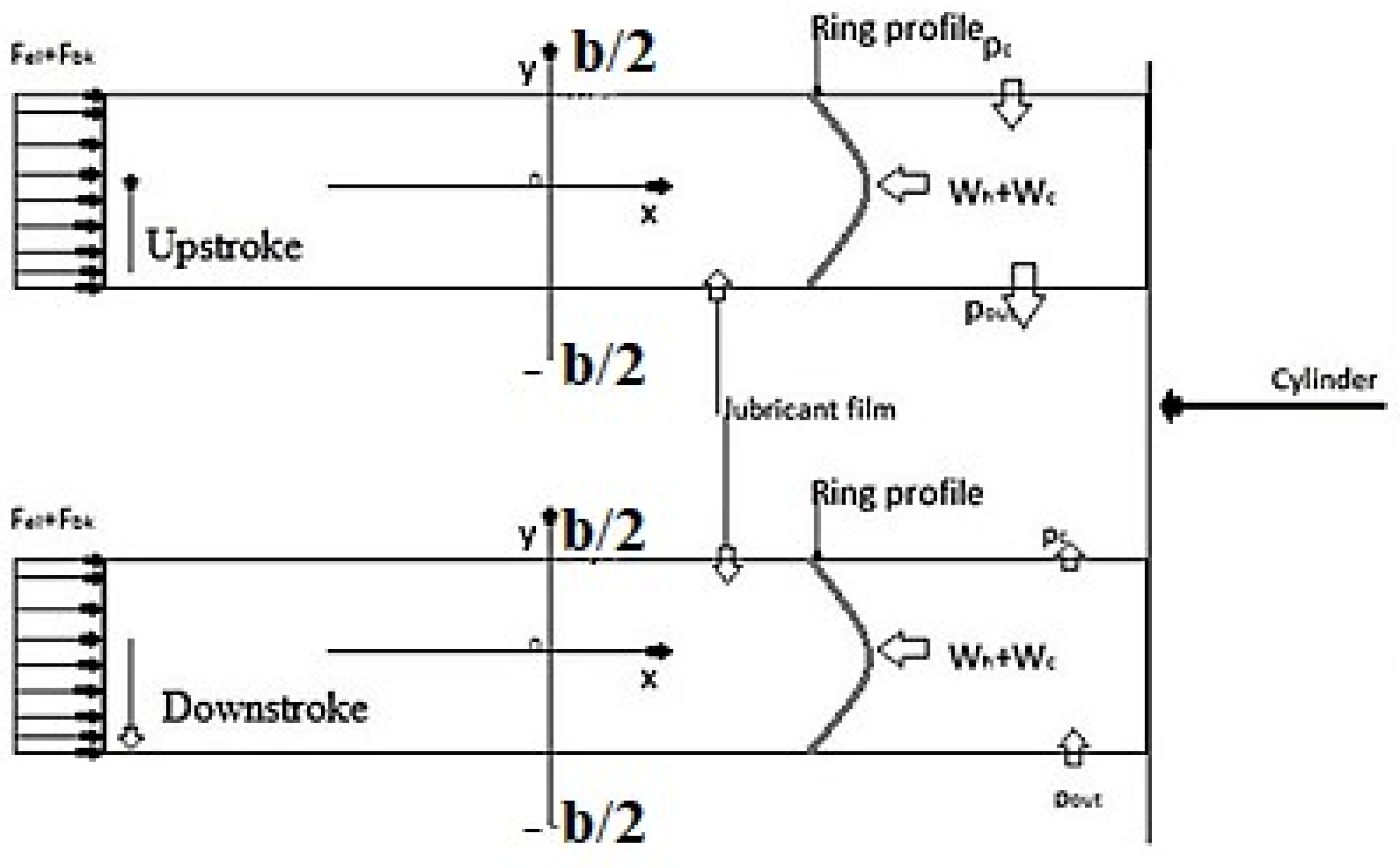
The gas pressure behind the ring is determined by considering the primary forces depicted in Figure 1, which are summarized as follows. The back-gas force is calculated as follows:
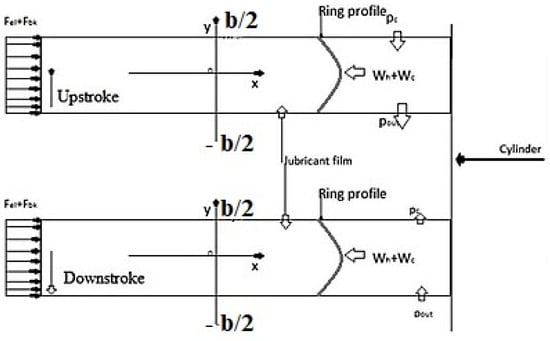
Figure 1.
Boundary flow conditions and forces in piston ring–cylinder liner contact.
Moreover, the ring tension force is defined as follows:
where the elastic pressure is obtained as follows:
where dgap represents the piston-ring end gap and dcyl stands for the cylinder bore diameter. In the present analysis, it is imperative that the ring tension force FT and the back-gas force FG are balanced with the hydrodynamic reaction Wh generated by the lubricant film in the ring–liner interface, as well as the load stemming from surface irregularities, denoted as WC. The balance of the ring must be maintained at every crankshaft angle, as per the following expression:
In the mixed and hydrodynamic lubrication regimes, the interface between the ring and the liner is not completely isolated by the lubricant film. Instead, a portion of the ring makes contact with surface asperities. The local hydrodynamic capacity and the load supported by these surface asperities are described as follows:
Load equilibrium is achieved when the relationship described in Equation (9) is verified as follows:
The phenomenon of mixed lubrication plays a critical role in the conjunction of piston rings, particularly in the context of rapidly fluctuating engine operating conditions. Its importance becomes most apparent as the piston ring approaches the dead centers, where speed reaches its minimum and contact load becomes predominant. To analyse this, we employ the stochastic model developed by Greenwood and Tripp [15], which helps predict the behavior of surface asperities and their influence on contact area. Greenwood and Tripp’s model, originally designed for two nominally flat and rough surfaces, serves as a conventional method for expressing the effects of asperities in the contact between the ring and the liner. However, for a more precise prediction of contact behavior between the ring and cylinder surfaces, statistical contact models have proven to be more valuable [10]. Numerous studies have endeavored to investigate the changes in surface topography during the running-in phase of engines, where the surfaces exhibit non-Gaussian characteristics. Consequently, it becomes evident that a comprehensive contact model is necessary to address both Gaussian and non-Gaussian surface profiles. This unmet need drives us to continually enhance the proposed model, demonstrating our ongoing commitment to improving its accuracy and applicability.
If we assume that the height distribution of asperities follows a Gaussian pattern, the resulting contact pressure can be expressed as follows:
where is the load carried by the asperities and is the corresponding contact area.
The probability distribution of asperity heights F5/2(λ), F2(λ) is analyzed with a fifth-order polynomial curve [16]. The stress on surface irregularities was assessed using the Greenwood–Tripp contact model [15]. In this model, σ represents the root mean square (RMS) of the surface quality of the contact surface. E′ stands for the effective modulus of elasticity of the ring insert system, and A represents the nominal contact area of the ring width. Additionally, ζκσ and κ denote the roughness parameter and roughness slope, respectively. Furthermore, the statistical function F5/2(λ) is expressed as a function of the Stribeck oil film parameter λ, which is defined as the ratio of the local oil film thickness (h(x, y)) to σ [18]. The boundaries between different lubrication states are used to show the changes in contact, and these states are represented with the minimum oil film thickness curve.
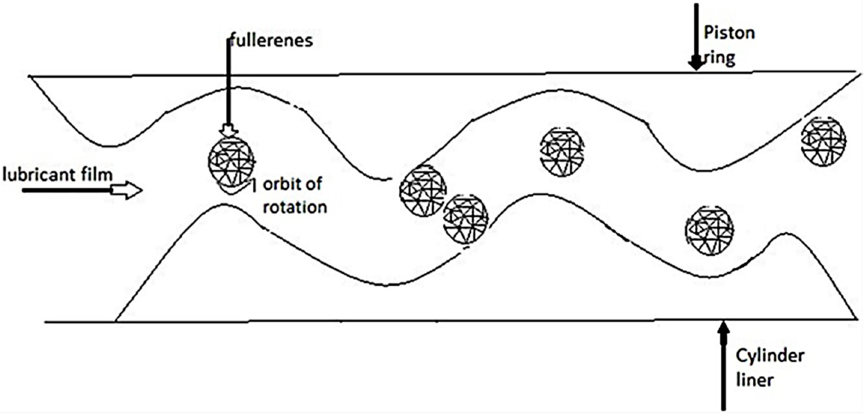
Figure 2, below, shows how the fullerenes really do affect the contact between the two surfaces and how their shape really does help and plays a key role in their role to reduce the friction and, as a result, the wear.
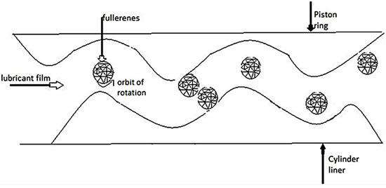
Figure 2.
Lubrication method of fullerenes lubricant in rough areas.
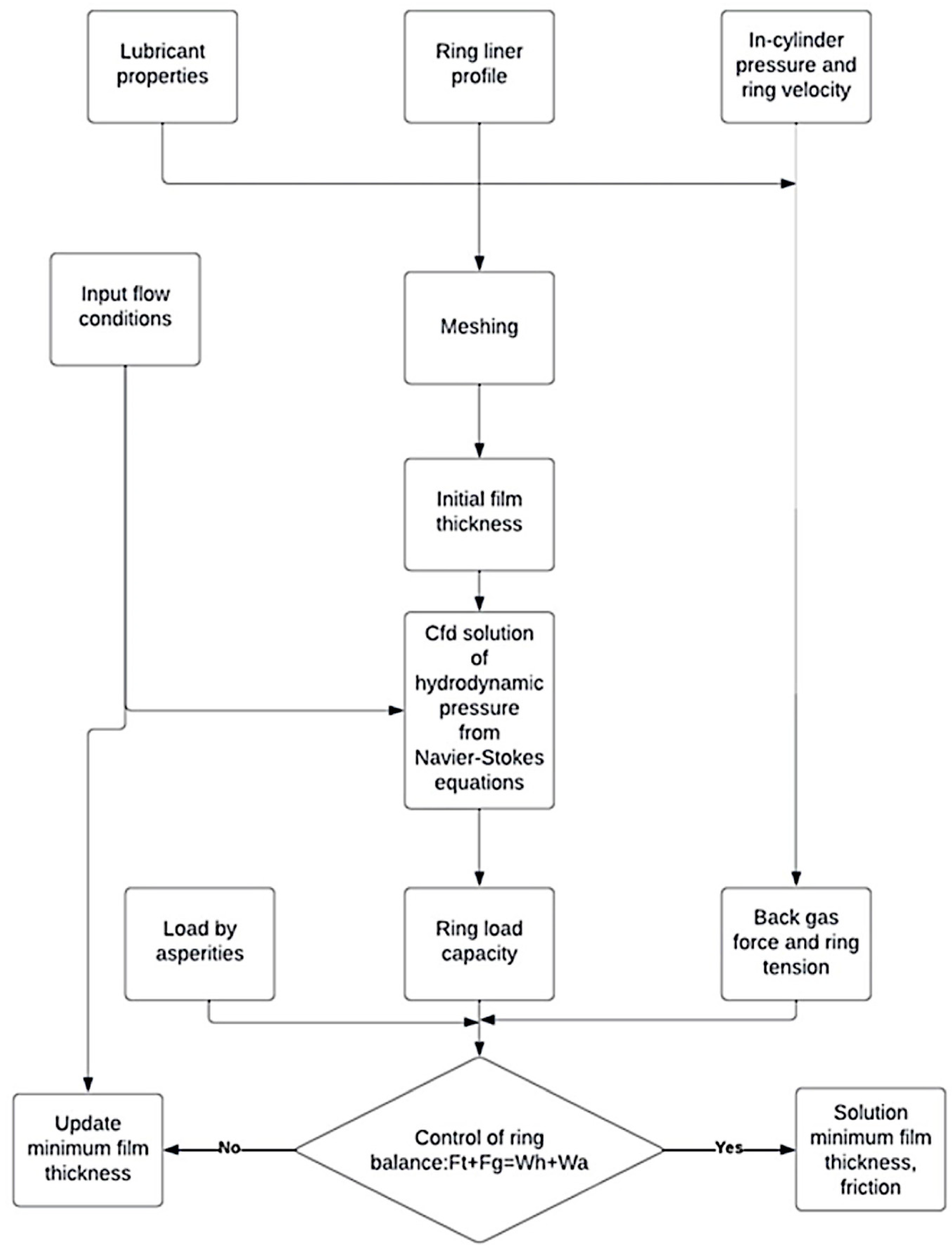
To enhance clarity, Figure 3 illustrates a summarized overview of the methodology for addressing the lubrication issue between the piston ring and cylinder.
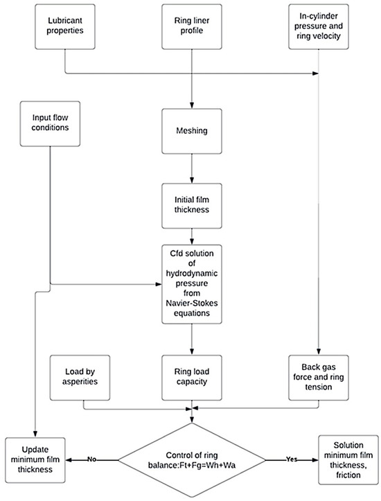
Figure 3.
Computational fluid dynamics (CFD) methodology for analyzing ring lubrication problems.
In the experimental setup [6], measurements of pressure within the engine cylinder were performed at 50% throttle. Notably, the point of highest chamber pressure occurs precisely 20 degrees after top dead center (TDC) during the power stroke. These gas pressure data are vital inputs for computational fluid dynamics (CFD) analysis, enabling the determination of ring friction and minimum thickness of lubricant’s film. Additionally, a comparative analysis of the engine’s performance in cold and hot states, especially concerning oil temperature, is presented. These specific operating conditions were chosen to simulate the low-speed conditions of the New European Driving Cycle (NEDC), encompassing both cold and warm-up tests [19]. It is worth mentioning that detailed specifications for the tested engine were provided by Zavos and Nikolakopοulos [6].
2.1. Analysis of Nanoparticles Motion
To simulate the motion of nanoparticles within the fluid, we focused on small, spherical particles in this case. Specifically, we employ the Basset–Boussinesq–Oseen equation. The governing equation is defined as follows (11):
- This mathematical expression characterizes the path followed by each particle within the lubricant’s motion. It essentially encapsulates Newton’s second law. On the left-hand side, it reflects the particle’s linear momentum change rate, while on the other side, it encompasses the combined influence of multiple forces, encompassing viscous, gravitational, buoyancy, virtual mass, and Basset forces exerted on the nanoparticle. As for the critical terms found on the right-hand side of Equation (12), their definitions are provided below:
- Stokes’ drag, which represents the drag force (F) acting on a sphere with a radius (a) as it moves through a fluid of viscosity (η) at a speed (v), is given by the following equation:
- The Froude–Krylov force is induced by the pressure gradient in the lubricant flow. It is crucial to highlight that the pressure gradient is calculated based on the Navier–Stokes equation, as shown below:
- The fluctuating force resulting from the added mass effect.
- The Basset force, along with other forces affecting the particle, such as the impact of Brownian motion, are not considered in this context because of the small size of the nanoparticles, which measure 70 nm.
- The effective lubricant viscosity is represented as a function of pressure and temperature, as per the Houpert investigation [20]:where the parameters So and Zo were ascertained by Gohar and Rahnejat [21].
Additionally, Rahman et al. [22] demonstrated that regulating the volume concentration of fullerene nanoparticle additives in mineral oil leads to a reduction in both friction and wear. When subjected to testing on a disk-on-disk type apparatus at a 200 N load, the friction coefficient reached 0.02, and the surface roughness decreased from 0.106 μm to 0.048 μm when utilizing fullerene nanoparticles at a concentration of 0.5 vol%. This investigation highlighted the noteworthy influence of the volume fraction of fullerene nanoparticles in governing the friction coefficient and wear magnitude.
The velocity of the lubricants, and of the fullerenes when they are used as additives, is of great interest. First, the velocity of the fullerenes takes values tending to 0 only in the region near the ring. This is because of the shear stress, which pushes the particles near to the piston ring.
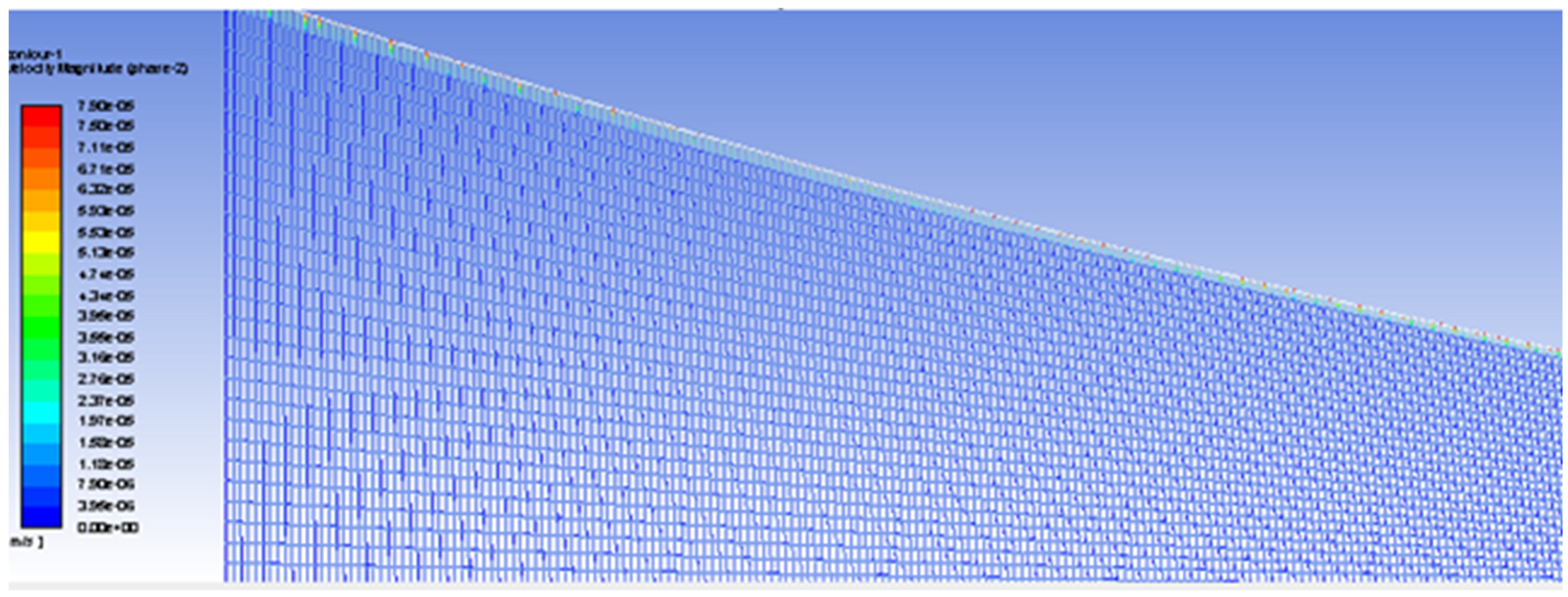
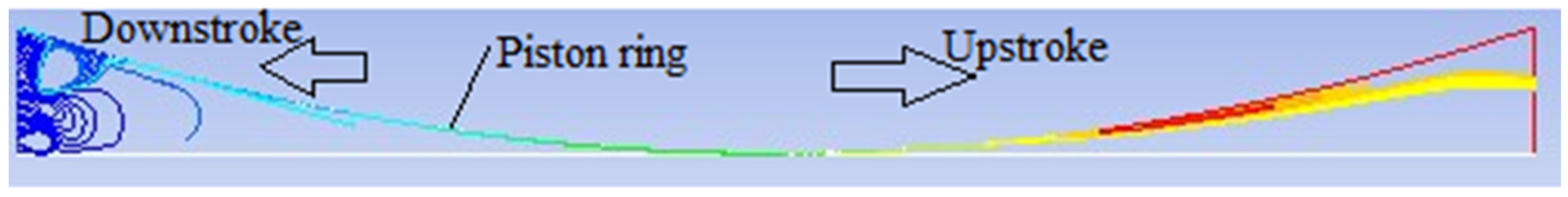
In order to fully understand the tribological properties of the fullerenes lubricant, it is crucial to see how the particles move during the flow. The piston ring moves, and its speed varies for every crank angle. This motion has a great effect on the flow, and by considering the shear stress which has been held, the particles should have trajectories near the piston ring. This is made clear from the velocity of the particles (phase 2) using the CFD model.
In Figure 4, above, the velocity magnitude of the particles is about 0 everywhere except for the area near the piston ring. This can be observed and confirmed from the particle’s trajectories. The CFD model gives the particles tracks, which confirm what has been expected (Figure 5). The particles only move in an area near the piston ring. In the inlet, turbulence can occur because the flow is not perfectly streamlined. Turbulence is characterized by irregular and chaotic fluid motion. When particles are introduced into a turbulent flow, they can become entrained in the swirling eddies and appear to spin or rotate as they move with the fluid.

Figure 4.
Nanoparticles’ velocity (m/s) magnitude at 398 K.

Figure 5.
Nanoparticles’ trajectories.
These two figures (taken for a crank angle of 180) show the way the particles act during the lubricant flow by considering the asperities loads and the temperature. Although the piston ring velocity depends on the crank angle, it does not affect the particles’ movement so much as the differential is only numerical.
2.2. Validation
The current simulation results of the lubrication model were compared with the friction results of Zhou et al. [23] and are presented in Figure 6. The deviation in friction force of the rough surface model is about 13%. The variation may be due to the thermal problem, which was not taken into account for the analysis performed by Zhou et al.
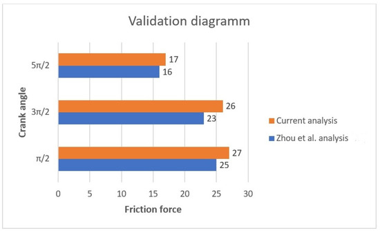
Figure 6.
Validation of friction force at different crank angles between current analysis and Zhou et al. [23].
3. Results
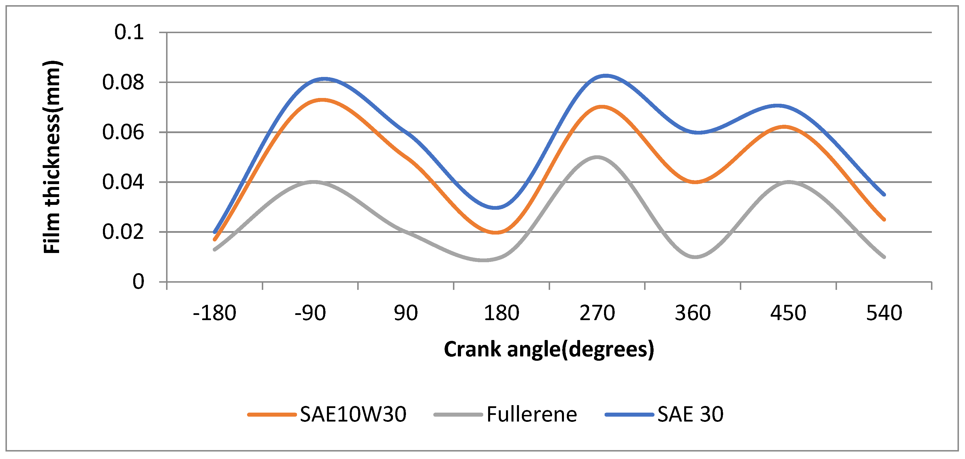
For the CFD model, the specifications of the engine mentioned before and described by Zavos and Nikolakopoulos [6] are used. The minimum film thickness is calculated from the simulations and shown in Figure 7. We observed that the lubricant 10W30 corresponds to a higher minimum film thickness while the fullerenes lubricants correspond to a lower film thicknesses. Respectively, SAE 30 corresponds to the highest values of film thickness among all the lubricants. This is observed in all phases of the combustion. This occurs since the lubricant with fullerenes as additives has a lower viscosity and retains its properties, as does the SAE10W30 lubricant, under all operating conditions.

Figure 7.
Comparison of the minimum film thickness at 398 K for three different oils: (i) SAE30, (ii) SAE10W30, (iii) with fullerenes as additives.
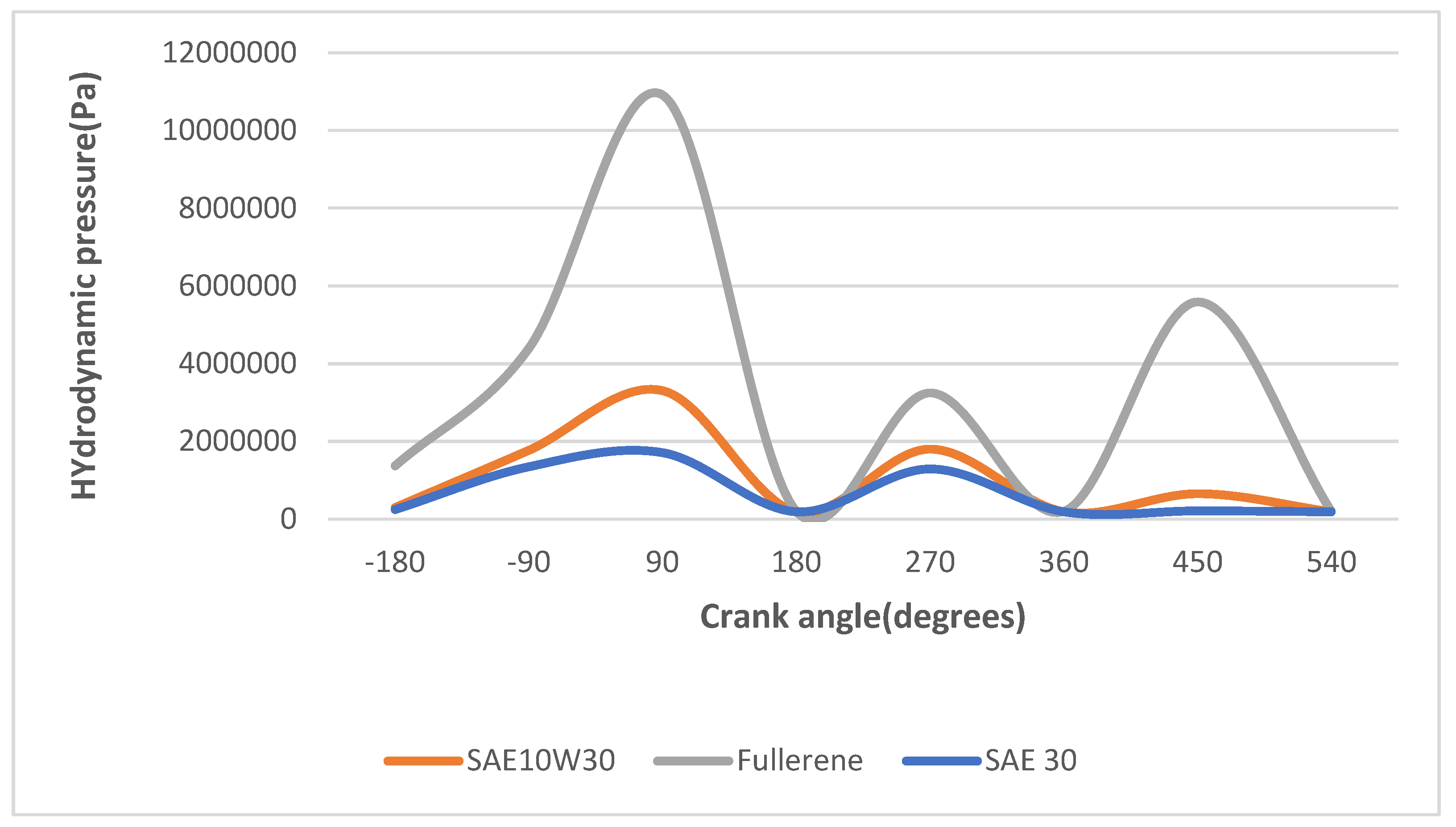
Furthermore, at each crank angle, the maximum hydrodynamic pressure is shown in Figure 8.
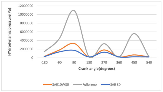
Figure 8.
The maximum hydrodynamic pressure at 398 K for three different oils: (i) SAE30, (ii) SAE10W30, (iii) with fullerenes as additives.
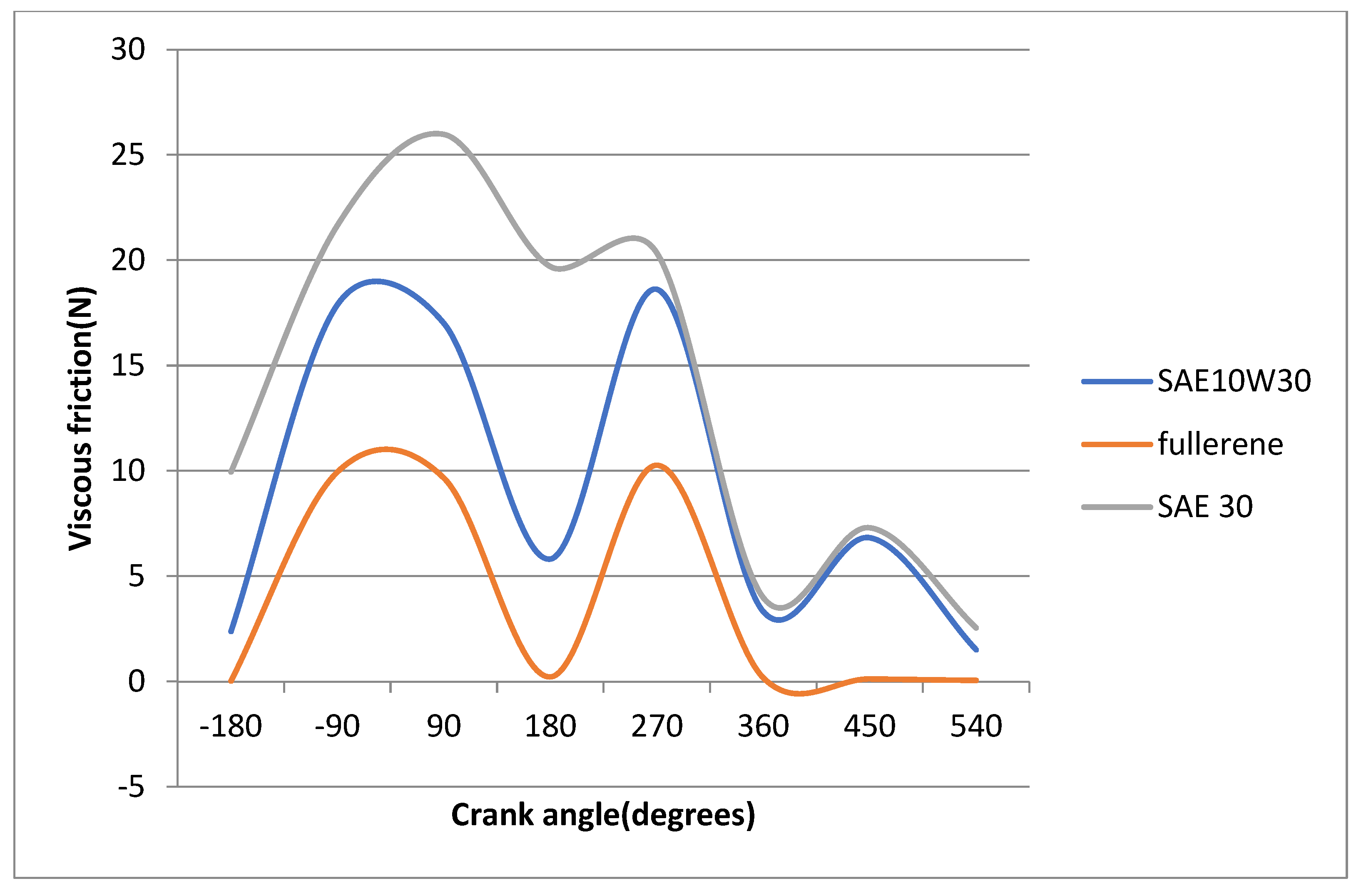
As expected, the pressure is higher if the film thickness is lower, and thus if the lubricant with C60 fullerenes as additives is used, the pressure is much higher. Consequently, the viscous friction, which causes wear and decreases the performance of the engine, has a notable difference between the three lubricants (Figure 9). This is because the viscous fiction depends on viscosity, which is much lower for the fullerenes lubricant. The friction is crucially affected by the shear stress, which is in turn affected by the pressure, as described by Zavos et al. [16].
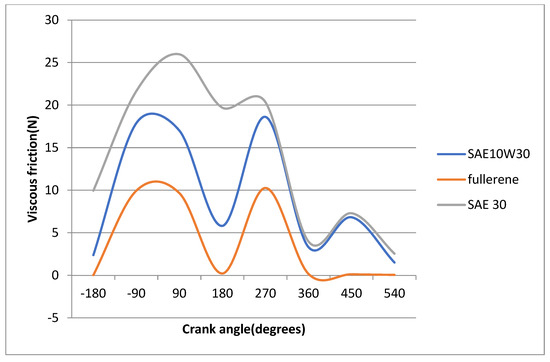
Figure 9.
Viscous friction at 398 K for three different oils: (i) SAE30, (ii) SAE10W30, (iii) with fullerenes as additives.
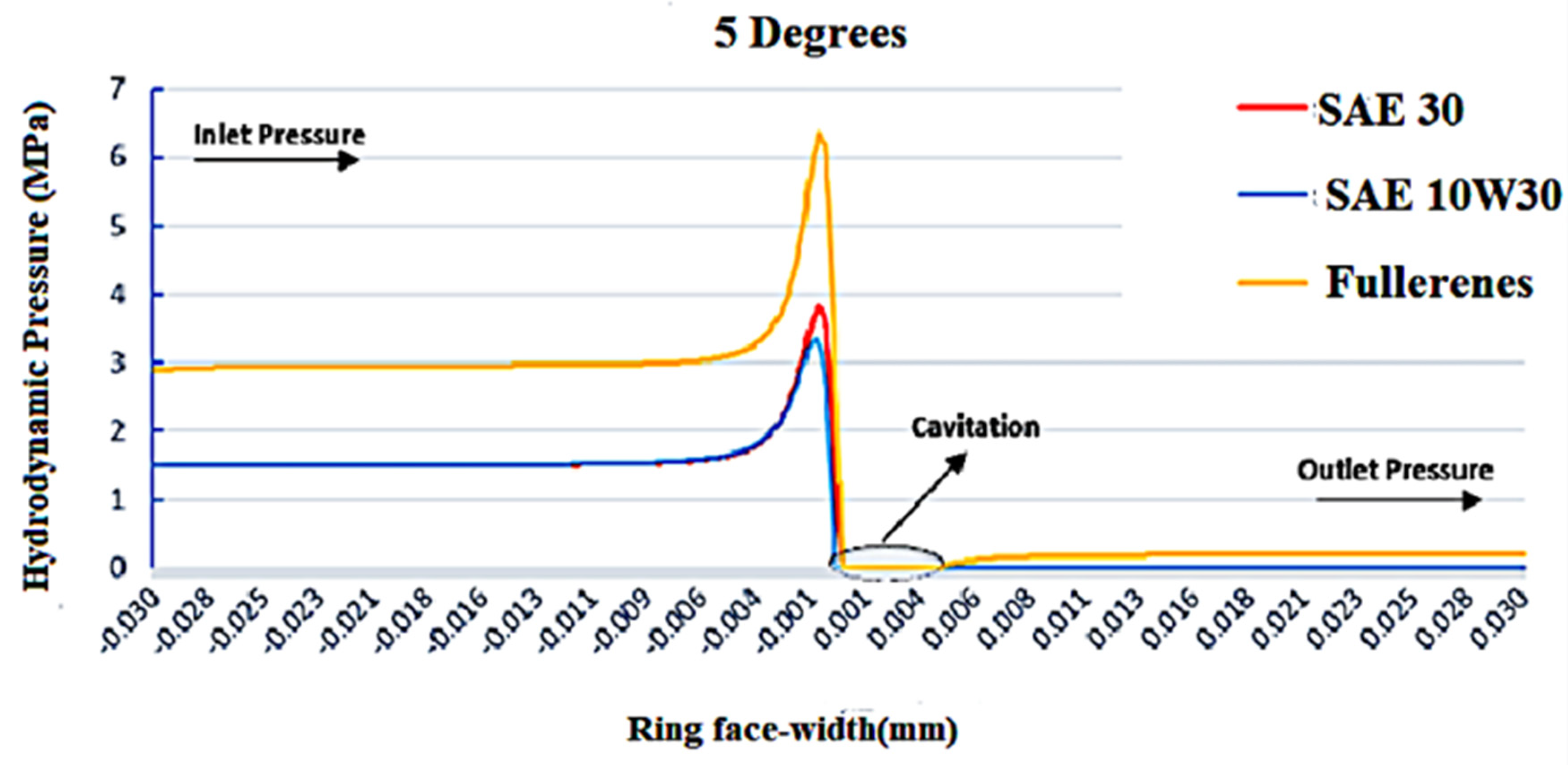
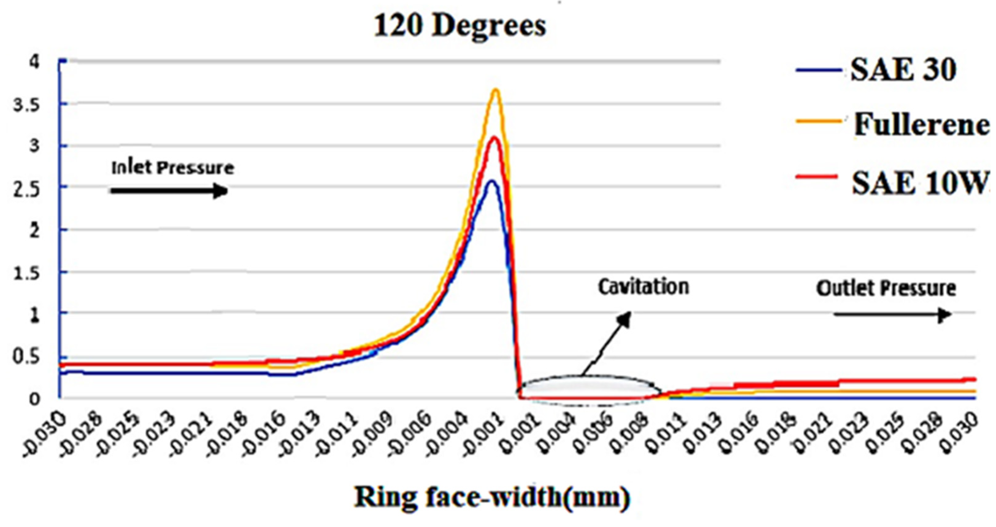
At 5 degrees, as shown in Figure 10, the hydrodynamic pressure is significantly higher when deploying lubricants using fullerenes as additives. When the strokes move on, and the crankshaft changes angle, the distribution of the pressure is expected to change. As seen in Figure 11, apart from the values that the pressure can reach, the way the pressure distributes among the ring face is similar to the previous.
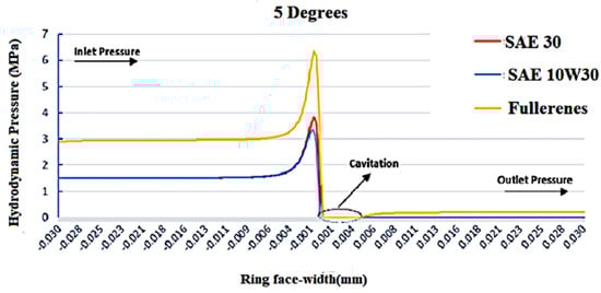
Figure 10.
Pressure distribution along the ring’s face when using the three different lubricants at a temperature of 398 K at a crankshaft angle of 5 degrees.

Figure 11.
Pressure distribution along the ring’s face when using the three different lubricants at a temperature of 398 K at a crankshaft angle of 120 degrees.
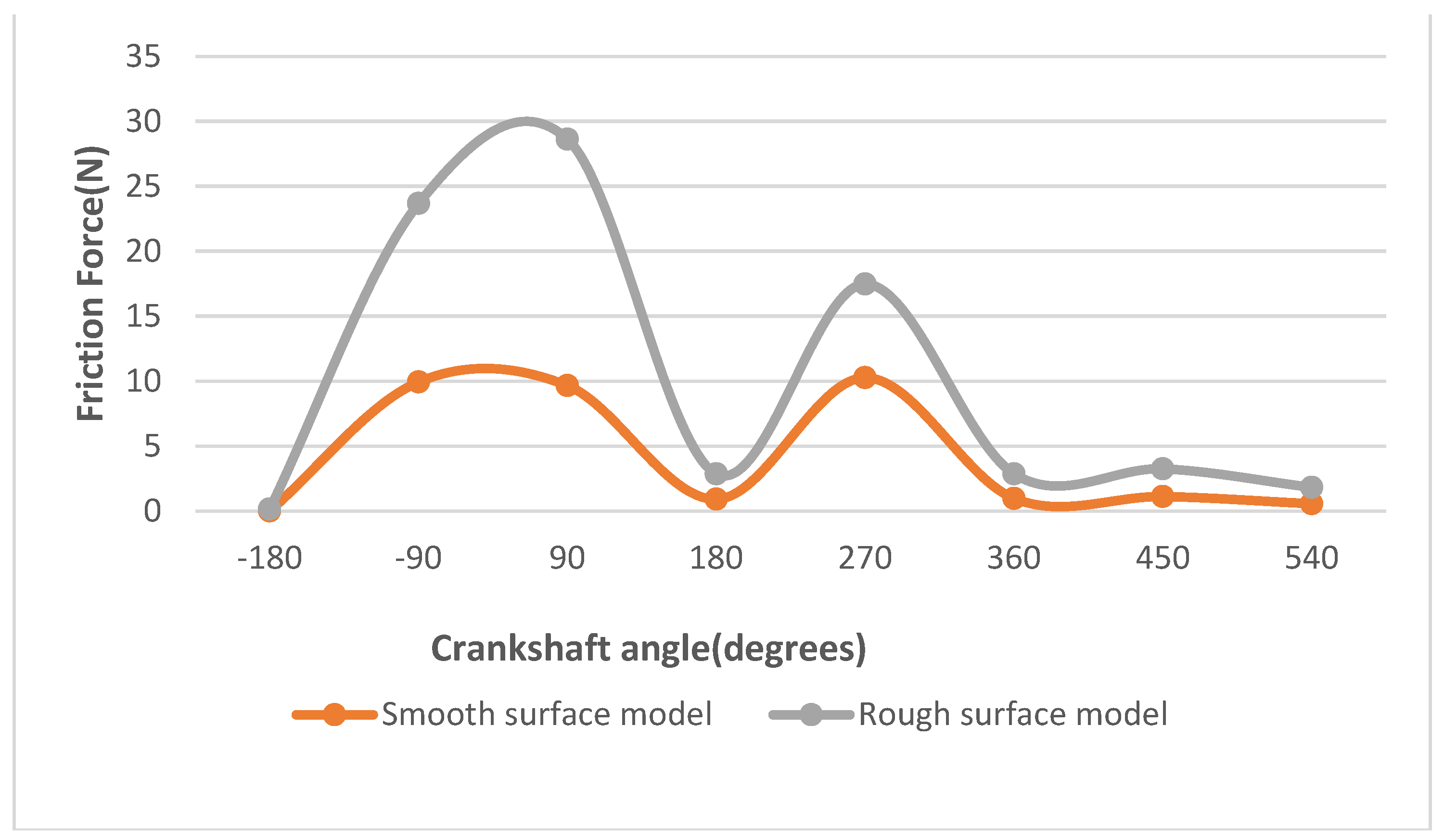
It is crucial and of great interest to see whether, and to what extent, roughness affects the friction and the lubricant itself. As shown below, there is a massive differential between the smooth surface model and the rough one. The lubricant with the C60 additives has been used in this case, and the results are indisputable.
The friction force varies about 50% between the two models (Figure 12). It is clearly observed that the roughness theory is of great importance and must be considered. Nevertheless, the temperature plays a key role in the lubricant’s properties and rheology. As such, we expected to see differences between the cold and hot start of an engine. A cold start is an attempt to start a vehicle’s engine when it is cold, relative to its normal operating temperature, often due to normal cold weather. A hot start, as expected, is the opposite situation.

Figure 12.
Friction force diagram of the rough surface model and smooth surface model at 120 °C (393 K) using the lubricant with fullerenes as additives.
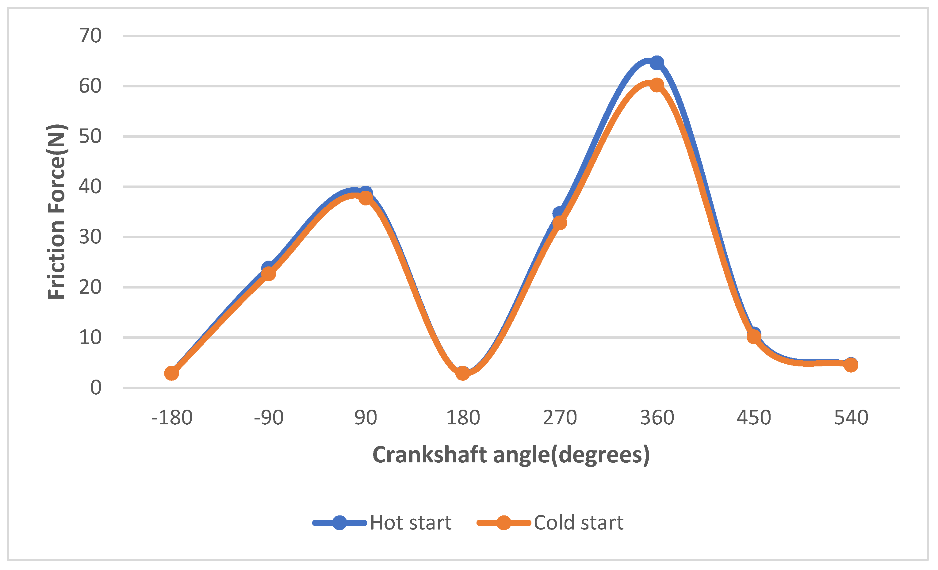
For the cold start, the cylinder temperature is considered to be 20 °C, while for a hot start, the temperature is considered to be 90 °C [16,24]. For both cases, the rough surface model and the lubricant with fullerenes as additives were used. The results are shown in Figure 13.

Figure 13.
Friction forces for hot and cold starts of an engine using the rough surface model for an engine using fullerene lubricant.
Lubricants are mainly used to reduce friction. In the cold working process, lubrication is easier for this lubricant (10W30 with fullerenes as additives); thus, the frictional coefficient is lower in cold working conditions. Zavos et al. [16] observed that under anticipated high-temperature engine conditions, the performance of the elastodynamic thin ring resulted in thinner lubricant films and elevated friction values.
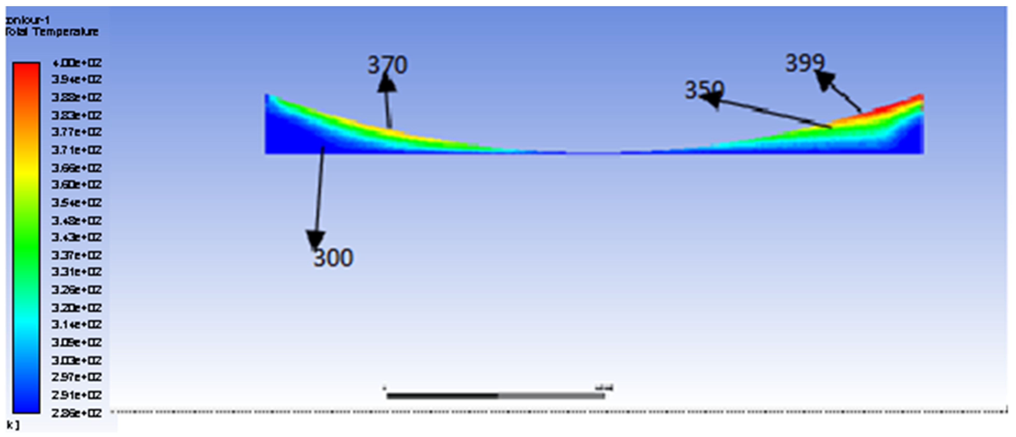
The temperature through the flow changes, and that change is what Figure 14 shows. As expected, the differential is observed near the piston ring, which has heat flux, and so the temperature varies in the area next to it. The temperature of the cylinder is considered to be 398 K.
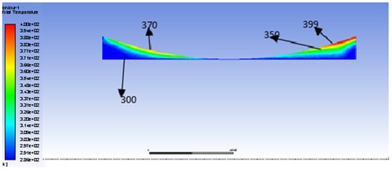
Figure 14.
Temperature distribution through lubricant SAE10W30 expressed in K degrees.
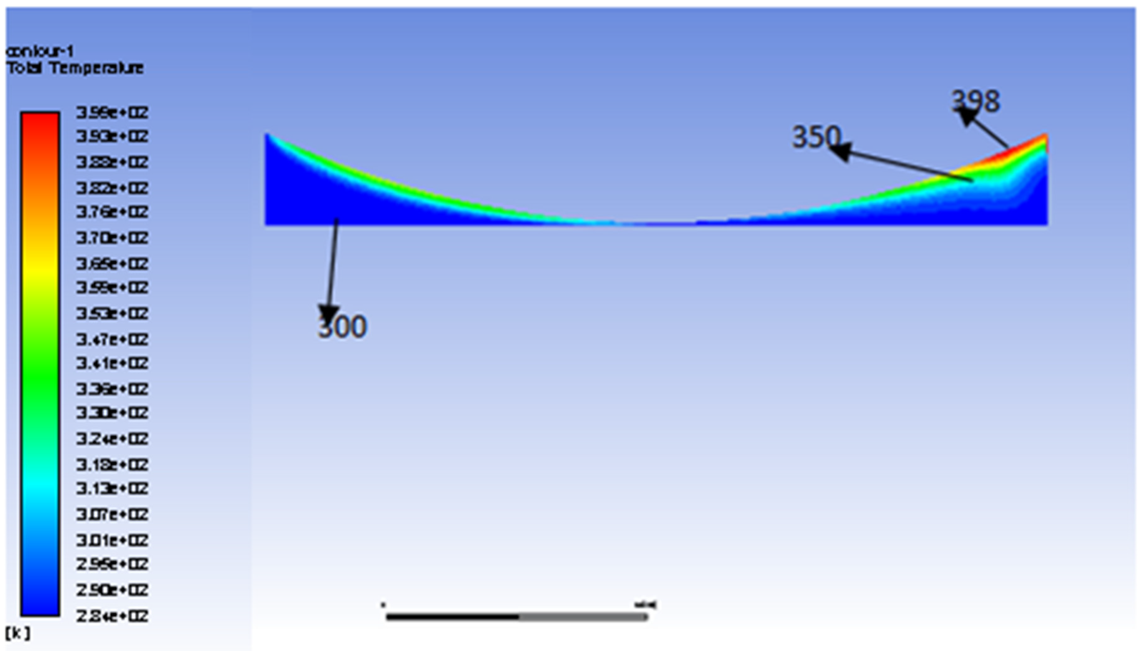
If the lubricant with fullerene additives is used, the temperature distribution is shown in Figure 15. It is observed that the temperature is similar between the lubricants, but the distribution is lower in the case of the fullerene lubricants, which causes the stability of its viscosity and its properties in general. This happens due to fullerenes thermal properties [25].
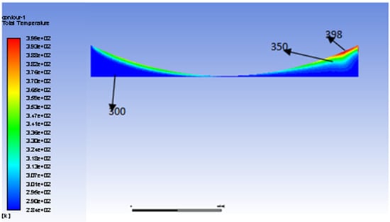
Figure 15.
Temperature distribution for lubricant with fullerenes expressed in K grades.
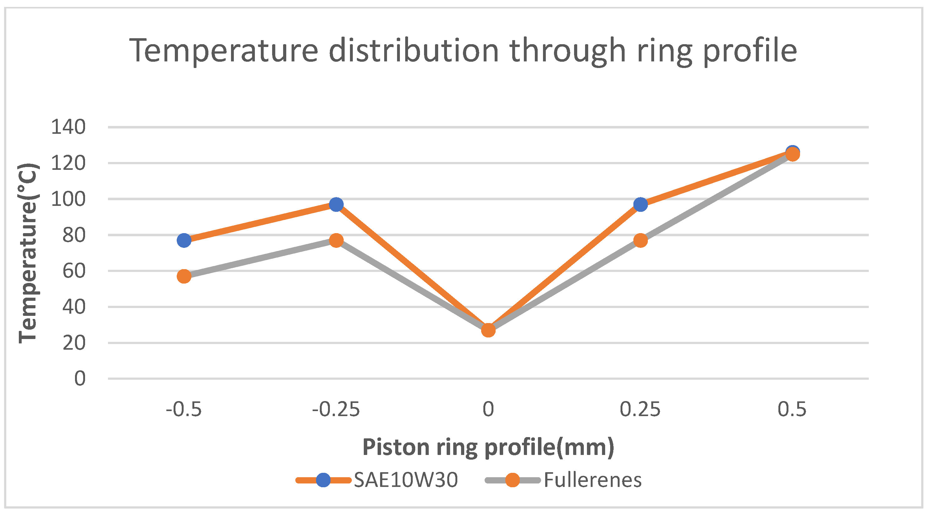
The temperature distribution through piston ring profile is shown in Figure 16, comparing the temperature for various points on the ring profile.
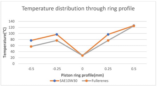
Figure 16.
Temperature distribution on the ring profile of SAE10W30 and fullerene oil.
This assumption has found significant practical applications within the piston ring–liner tribological system, as demonstrated by various researchers who have achieved promising predictions closely aligned with experimental data. Recent studies by Zavos and Nikolakopoulos [18], Gore et al. [26], and Söderfjäll et al. [27] have placed a strong emphasis on studying the piston ring interface, combining numerical predictions with direct measurements that have been well-verified. It is worth noting that the shape and roughness of the ring can indeed influence lubrication mechanisms, particularly in the mixed and hydrodynamic regimes. This effect has been explored in prior works [18], revealing variations in the range of 5–25% depending on the operating conditions. Therefore, the primary contribution of this study lies in its investigation of the impact of lubricants containing nanoparticles, using an advanced CFD model, to further enhance our understanding of this complex system.
We created a simulated piston ring with a parabolic artificial ring profile, constructed as a thin ring coated with hard chrome plating. You can find comprehensive information on the entire piston assembly in Table 1.

Table 1.
Fundamental CFD model parameters for piston ring–liner contact.
4. Discussion
Based on the results observed, it is evident that lubricants containing fullerene additives hold significant importance. The utilization of such lubricants effectively reduces friction forces and consequently minimizes wear. Therefore, it can be readily concluded that these lubricants play a pivotal role in extending the longevity of engine performance, as the friction force is significantly lower compared to synthetic oils, as shown in Figure 9. This novel class of lubricants is garnering considerable interest, not only for their performance but also within the research community.
The phenomenon of friction between solid surfaces is profoundly influenced by the presence of surface asperities, which are often imperceptible to the naked eye but have a profound impact at the microscopic level. When two solid surfaces make contact, these surface irregularities introduce several key factors that contribute to an increase in frictional force, which can be easily observed from Figure 12. Firstly, asperities facilitate mechanical interlocking and adhesion between surfaces, driven by attractive forces such as van der Waals interactions. Secondly, they significantly increase the effective contact area between the surfaces, creating numerous additional points of contact. Additionally, surface roughness resulting from asperities causes peaks to climb over each other during relative motion, amplifying the resistance to sliding. Furthermore, under load, these asperities undergo elastic deformation, elevating the normal force and, consequently, the frictional force. Lastly, surface chemistry at the asperities can enhance chemical bonding, further augmenting friction. Hence, accounting for surface asperities is imperative for a comprehensive understanding of friction and is crucial for optimizing tribological performance in various engineering applications.
5. Conclusions
In this paper, a 2D CFD model was developed to study the effect of lubricants containing fullerenes against synthetic oils in the tribological performance of a compression piston ring system. The temperature and toughness effects have been included. The model was validated against another similar model. From the obtained results, the below main conclusions may be drawn:
- In Figure 7, the highest film thickness concerning fullerenes lubricants can be achieved at 270 degrees of crank angle. The maximum variation of the minimum film thickness compared to the synthetic lubricant SAE10W30 is estimated to be 30%.
- The friction force reaches the minimum at 180 degrees of crank angle. The maximum variation of friction force between fullerenes and the synthetic lubricant SAE10W30 reaches the value of 42%. This is clearly shown in Figure 9.
- In Figure 12, regarding the fullerene oils, the friction force varies by almost 50% between the smooth and rough surface model.
- Regarding the temperature distribution along the ring width, the fullerene oils show lower temperatures than the synthetic oil, as per Figure 16. This is due to the thermal properties of the fullerene C60 additives, which assist the heat transfer.
An ongoing project would be to include the elastic and the cavitation effects, as well as an experimental characterization of fullerene C60 oils, and a tribological characterization using a block-on-ring tester and a real motorbike single-cylinder engine.
Author Contributions
Conceptualization, writing—review and editing, P.N.; writing original draft preparation, methodology CFD model and UDF code, E.T. All authors carried out interpretations for the results. All authors have read and agreed to the published version of the manuscript.
Funding
This research received no external funding.
Data Availability Statement
Data are contained within the article.
Conflicts of Interest
The authors declare no conflict of interest.
Nomenclature
| A | nominal contact area |
| Ac | asperity contact area |
| b | ring face-width |
| dgap | ring end gap |
| E’ | equivalent (reduced) modulus of elasticity |
| Ering | Young’s modulus of elasticity of the ring |
| El | Young’s modulus of elasticity of the liner |
| F | applied ring load |
| FG | combustion gas force |
| FT | ring tension force |
| F5/2, F2 | statistical functions |
| H | lubricant film thickness |
| Hmin | minimum film thickness with time |
| Hs | ring axial profile |
| Iring | second moment of ring area |
| ph | hydrodynamic pressure |
| pel | ring elastic pressure due to fitment |
| pbk | ring back-gas pressure acting behind the inner ring rim |
| pc | contact pressure |
| pout | outlet pressure at the ring conjunction |
| patm | ambient pressure |
| rcr | crank-pin radius |
| ro | nominal bore radius |
| t | time |
| w | ring radial width |
| Wc | load share of asperities |
| Wh | load carried by the lubricant film |
| X | parameter for load balance criterion |
| Greek Symbols | |
| A | modified pressure–viscosity coefficient |
| δp | local contact deformation |
| ζ | surface density of asperity peak |
| κ | average asperity tip radius |
| λ | Stribeck oil film parameter |
| λCR | control ratio |
| µ | lubricant dynamic viscosity |
| µo | ambient dynamic viscosity |
| ρ | lubricant density |
| ρo | lubricant density at atmospheric pressure and ambient temperature |
| σ | root mean square roughness value of examined tribopair |
| ς | coefficient parameter of boundary shear strength |
| τ | viscous shear stress |
| τo | Eyring shear stress of the lubricant film |
| υring | ring sliding velocity |
| φ | crank angle |
| χ | step for minimum film thickness loop |
| ω | rotational crankshaft speed |
| Abbreviations | |
| BDC | bottom dead center |
| CFD | computational fluid dynamics |
| NEDC | New European Driving Cycle |
| RS | root square |
| TDC | top dead center |
References
- Spikes, H. Friction Modifier Additives. Tribol. Lett. 2015, 60, 5. [Google Scholar] [CrossRef]
- Rudnick, L.S. Lubricant Additives—Chemistry and Applications, 2nd ed.; CRC Press: Boca Raton, FL, USA, 2009. [Google Scholar]
- Lee, K.; Hwang, Y.; Cheong, S.; Kwon, L.; Kim, S.; Lee, J. Performance evaluation of nano-lubricants of fullerene nanoparticles in refrigeration mineral oil. Curr. Appl. Phys. 2009, 9, e128–e131. [Google Scholar] [CrossRef]
- Padgurskas, J.; Rukuiza, R.; Prosyčevas, I.; Kreivaitis, R. Tribological propertiesof lubricant additives of Fe, Cu and Co nanoparticles. Tribol. Int. 2013, 60, 224–232. [Google Scholar] [CrossRef]
- Wan, Q.; Jin, Y.; Sun, P.; Ding, Y. Tribological Behaviour of a Lubricant Oil Containing Boron Nitride Nanoparticles. Procedia Eng. 2015, 102, 1038–1045. [Google Scholar] [CrossRef]
- Zavos, A.; Nikolakopoulos, P.G. Tribology of new thin compression ring of fired engine under controlled conditions—A combined experimental and numerical study. Tribol. Int. 2018, 128, 214–230. [Google Scholar] [CrossRef]
- Morris, N.; Mohammadpour, M.; Rahmani, R.; Johns-Rahnejat, P.M.; Rahnejat, H.; Dowson, D. Effect of cylinder deactivation on tribological performance of piston compression ring and connecting rod bearing. Tribol. Int. 2018, 120, 243–254. [Google Scholar] [CrossRef]
- Shahmohamadi, H.; Rahmani, R.; Rahnejat, H.; Garner, C.P.; King, P.D. Thermo-mixed hydrodynamics of piston compression ring conjunction. Tribol. Lett. 2013, 51, 323–340. [Google Scholar] [CrossRef]
- Bewsher, S.R.; Mohammadpour, M.; Rahnejat, H.; Offner, G.; Knaus, O. An investigation into the oil transport and starvation of piston ring pack. Proc. Inst. Mech. Eng. Part J 2018, 233, 112–124. [Google Scholar] [CrossRef]
- Rahmani, R.; Rahnejat, H.; Fitzsimons, B.; Dowson, D. The effect of cylinder liner operating temperature on frictional loss and engine emissions in piston ring conjunction. Appl. Energy 2017, 191, 568–581. [Google Scholar] [CrossRef]
- Baker, C.; Theodossiades, S.; Rahmani, R.; Rahnejat, H.; Fitzsimons, B. On the transient three-dimensional tribodynamics of internal combustion engine top compression ring. J. Eng. Gas Turbines Power 2017, 139, 062801. [Google Scholar] [CrossRef]
- Besser, C.; Schneidhofer, C.; Dörr, N.; Novotny-Farkas, F.; Allmaier, G. Investigation of long-term engine oil performance using lab-based artificial ageing illustrated by the impact of ethanol as fuel component. Tribol. Int. 2012, 46, 174–182. [Google Scholar] [CrossRef]
- Sikora, G.; Miszczak, A. The Influence of Oil Ageing on the Change of Viscosity and Lubricity of Engine Oil. Solid State Phenom. 2013, 199, 182–187. [Google Scholar] [CrossRef]
- Dam, M.; Nuszkowski, J.; Thompson, G.J. Effects of Oil Aging on Laboratory Measurement of Emissions from a Legacy Heavy-Duty Diesel Engine; SAE Technical Paper No. 2011-01-1163; SAE Technical: Warrendale, PA, USA, 2011. [Google Scholar]
- Greenwood, J.A.; Tripp, J.H. The contact of two nominally flat rough surfaces. Proc. Inst. Mech. Eng. 1970, 185, 625–633. [Google Scholar] [CrossRef]
- Nikolakopoulos, P.G.; Mavroudis, S.; Zavos, A. Lubrication performance of engine commercial oils with different performance levels: The effect of engine synthetic oil aging on piston ring tribology under real engine conditions. Lubricants 2018, 6, 90. [Google Scholar] [CrossRef]
- Ma, W.; Biboulet, N.; Lubrecht, A.A. Performance evolution of a worn piston ring. Tribol. Int. 2018, 126, 317–323. [Google Scholar] [CrossRef]
- Zavos, A.; Nikolakopoulos, P. Thermo-mixed lubrication analysis of coated compression rings with worn cylinder profiles. Ind. Lubr. Tribol. 2017, 69, 15–29. [Google Scholar] [CrossRef]
- Zhu, C.; Fan, L.-S. Chapter 18—Multiphase Flow: Gas/Solid. In The Handbook of Fluid Dynamics; Johnson, R.W., Ed.; Springer: Berlin/Heidelberg, Germany, 1998; ISBN 9783540646129. [Google Scholar]
- Houpert, L. New results of traction force calculations in elastohydrodynamic contacts. J. Tribol. 1985, 107, 241–245. [Google Scholar] [CrossRef]
- Gohar, R.; Rahnejat, H. Fundamentals of Tribology; Imperial College Press: London, UK, 2008. [Google Scholar]
- Rahman, M.M.; Islam, M.; Roy, R.; Younis, H.; Al Nahyan, M.; Younes, H. Carbon Nanomaterial-Based Lubricants: Review of Recent Developments. Lubricants 2022, 10, 281. [Google Scholar] [CrossRef]
- Zhou, Q.-B.; Zhu, T.-Z.; Wang, R.-S. A full lubrication model for rough surface piston rings. Tribol. Int. 1988, 21, 211–214. [Google Scholar]
- Zavos, A.; Nikolakopoulos, P.G. A tribological study of piston rings lubricated by power law oils. Proc. Inst. Mech. Eng. Part J J. Eng. Tribol. 2016, 230, 506–524. [Google Scholar] [CrossRef]
- Reding, B.; Khayet, M. Thermal conductivity and thermal diffusivity of fullerene-based nanofluids. Sci. Rep. 2022, 12, 9603. [Google Scholar] [CrossRef] [PubMed]
- Gore, M.; Rahmani, R.; Rahnejat, H.; King, P. Assessment of friction from compression ring conjunction of a high-performance internal combustion engine: A combined numerical and experimental study. Proc. Inst. Mech. Eng. Part C J. Mech. Eng. Sci. 2016, 230, 2073–2085. [Google Scholar] [CrossRef]
- Söderfjäll, M.; Almqvist, A.; Larsson, R. Component test for simulation of piston ring–cylinder liner friction at realistic speeds. Tribol. Int. 2016, 104, 57–63. [Google Scholar] [CrossRef]

Disclaimer/Publisher’s Note: The statements, opinions and data contained in all publications are solely those of the individual author(s) and contributor(s) and not of MDPI and/or the editor(s). MDPI and/or the editor(s) disclaim responsibility for any injury to people or property resulting from any ideas, methods, instructions or products referred to in the content. |
© 2023 by the authors. Licensee MDPI, Basel, Switzerland. This article is an open access article distributed under the terms and conditions of the Creative Commons Attribution (CC BY) license (https://creativecommons.org/licenses/by/4.0/).