Article

Measurement for Lubricant Distribution in an Angular Contact Ball Bearing and Its Influence Investigation

1
School of Mechanical Engineering and Automation, Dalian Polytechnic University, Dalian 116034, China
2
College of Locomotive and Rolling Stock Engineering, Dalian Jiaotong University, Dalian 116028, China
3
China North Vehicle Research Institute, Beijing 100072, China
*
Author to whom correspondence should be addressed.
Lubricants 2023, 11(2), 63; https://doi.org/10.3390/lubricants11020063
Submission received: 12 December 2022 / Revised: 18 January 2023 / Accepted: 31 January 2023 / Published: 3 February 2023
(This article belongs to the Special Issue Friction and Lubrication of Sliding Bearings, Volume II)

Abstract

:
Oil lubrication is widely adopted in rolling bearings, the characteristics of which affect the oil film formation and friction state, and also the heat generation and dissipation characteristics. However, it is difficult to measure the internal lubrication of rolling bearings in practice, which is of great importance for lubrication and structure design. In this work, one measurement system for lubricant distribution was built and installed on a test rig to obtain original pictures of the lubricant in bearings. Grayscale images were obtained by picture processing to characterize the lubricant distribution, and the image pixels were evaluated for the characterization of lubricant volume. Finally, the measurement of the lubricant distribution in the angular ball bearing was carried out under different lubrication and cage groove conditions, and their influences were investigated. The results show that the lubricant distribution is affected by the oil jet nozzle angle, operating speed, and cage structure. The lubricant capacity among balls and the cage pocket in bearings gradually increased with the increase in the nozzle angle and the depth of the cage grooves, but decreased with the increasing operating speed. The experimental results are helpful to provide a basis for the structure and lubrication design of ball bearings.

1. Introduction

The rolling bearing is one of the key parts of rotating machinery equipment, which may directly affect the performance of the whole machine. Rolling bearings most commonly adopt oil jet lubrication, and the flow characteristics of the lubrication will affect the oil film formation and friction state of the rolling contact interface, and also the heat generation and dissipation characteristics directly related to thermal and flow properties for lubrication in bearings, so the lubrication characteristics are key for the rolling bearings [1,2]. Once the lubrication condition in a rolling bearing is poor, the friction and wear of the bearing’s internal contact area will be intensified, which can easily produce overheating damage, and then cause premature bearing failure [3,4].
A bearing’s lubricant distribution directly affects its lubrication characteristics and is one of the vital factors to be considered in the lubrication design [5] and structural design of rolling bearings [6]. In particular, the cage structure directly affects its motion [7] and also the lubrication characteristics [8]. Therefore, it is of great significance to carry out the lubricant distribution measurement of angular contact ball bearings and study the influence of lubrication and cage structure on bearings’ internal lubricant distribution [9].
Oh [10] used flow field simulation techniques of computational fluid dynamics to analyze the three-dimensional air flow behavior in a ball bearing. Yan [11,12] set up a highly precise numerical model with different nozzle distributions and used the VOF method to track the oil–air interface. Liu [13] used a fluid–structure coupled simulation model based on the CFD method of air–oil two-phase flow (AOTPF) in the bearing to discuss the lubricating characteristics of an oil jet-lubricated ball bearing in the gearbox. Peterson [14,15] used ANSYS FLUENT computational fluid dynamics (CFD) software to develop a full-scale model of a single-phase oil flow in a deep-groove ball bearing (DGBB), and measured the frictional torque of oil-lubricated rolling element bearings compared to fluid drag losses with CFD simulations. Wu [16,17] and Hu [18] proposed two-phase flow inside the ball bearing considering heat transfer and oil jet cooling for high-speed ball bearings, investigated by the average oil volume fraction. Ma [19] developed an algorithm for calculating roller pocket oil film pressure and film thickness and studied the effects of inner ring rotation speed, cage angular acceleration, and so on. Wu [20] investigated the air–oil two-phase flow inside an oil jet-lubricated ball bearing by the CFD method, validated by measuring the temperature of the outer ring. Aidarinis [21] devised an experimental flow field inside the bearing’s external chamber using a laser Doppler anemometry system and carried out simulations under real operating conditions both for the air flow and for the lubricant oil flow and for a range of shaft rotating speeds, then computed the behaviors by fluid dynamics (CFD) modeling. Chen [22] established a transient air–oil two-phase flow model in a ball bearing based on computational fluid dynamics (CFD) to investigate the behaviors of oil transfer and air–oil flow under different capillary conditions with speed, surface tension, and viscosity and found that the oil distribution and air–oil flow behaviors in a ball bearing are strongly related to the speed and the ratio of oil viscosity.
Nitric oxide laser-induced fluorescence imaging methods [23] and PIV (Micro-Particle Image Velocimetry) [24,25] are used to measure the grease velocity vector field. Maccioni [26,27] designed a dedicated test rig to perform Particle Image Velocimetry (PIV) measurements on the lubricant inside a tapered roller bearing using a sapphire outer ring. Arya [28] studied the oil flow inside an angular contact ball bearing using Bubble Image Velocimetry (BIV). The oil flow inside the cage and bearing was analyzed using a high-speed camera, and the observed oil flow streamlines demonstrated the influence of operating conditions and cage designs on fluid flow. Wang [29,30] proposed a novel experimental method that combines synchronized dual-camera imaging with laser-induced fluorescence (LIF) using extra illumination to observe the oil flow in a ball bearing, and then observed the distribution of the lubricant film with an outer ring replaced by a glass ring.
The above effects of bearing structure characteristics on bearing lubrication flow field were mostly calculated based on simulation models. In terms of experiments, the influence of operating conditions and structure on bearing lubrication is mainly analyzed through testing bearing temperature and flow rate, among others, while the influence of cage groove on a bearing’s internal lubricant distribution using a transparent cage is rarely studied. In view of this, taking angular contact ball bearings as the research object, a measurement method of lubricant distribution in a bearing was proposed, and the influences of different lubrication conditions and cage grooves on lubricant distribution in bearings were analyzed by experiments.

2. Measurement for Lubricant Distribution in an Angular Contact Ball Bearing

2.1. Test Rig

The test rig was specifically built to investigate the lubrication distribution characteristics in an angular contact ball bearing, as shown in Figure 1. The test rig mainly consists of the drive system, an oil lubrication system, a horizontal two-support rotor system, the tested bearing, and a specified measurement system for lubricant distribution, among others.
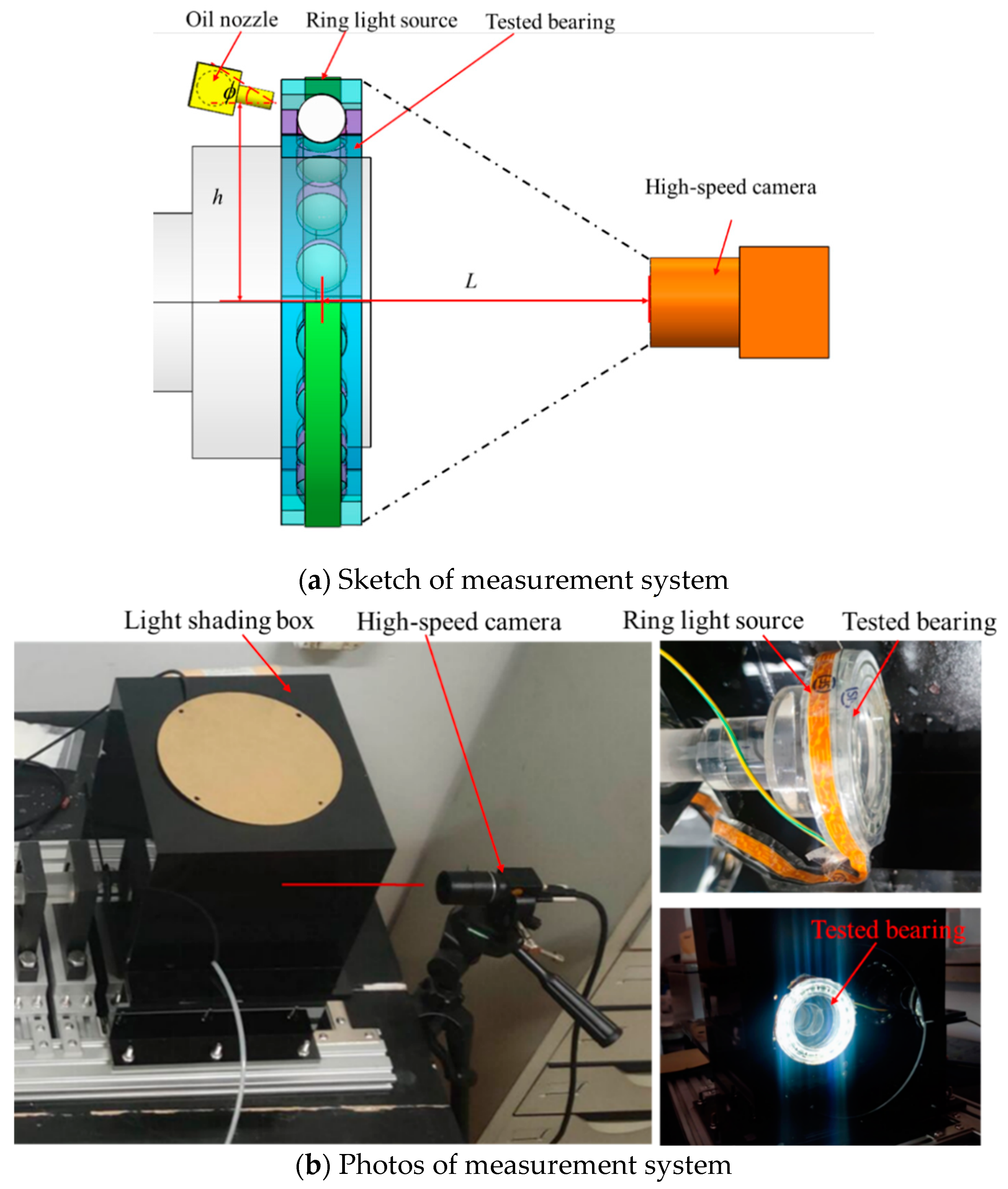
The measurement system for lubricant distribution consisted of a high-speed camera, a ring light source, and a light shading box, as shown in Figure 2. The high-speed camera was arranged in a coaxial position with the tested bearing. A ring light source on the outer ring was adopted to illuminate the whole bearing, and a light shading box was designed with black acrylic material to reduce the impact of the external ambient light.

2.2. Tested Bearing

The tested bearing was specially designed with a transparent material in order to observe the lubricant, the structural parameters of which are same as the 7013C bearing, as shown in Table 1. Transparent glass and resin materials were used for the balls and the other parts (including inner and outer ring, cage), as shown in Figure 3.
Meanwhile, in order to increase the permeability of the tested bearing and avoid light refraction, the rotor was customized with transparent acrylic material, as shown in Figure 4.

2.3. Measurement for Lubricant Distribution

The tested bearing was lubricated by intermittent oil injection with the oil supply of 5 L/min and the time interval of 10 s. The oil jet nozzle was set on the guiding surface area for side-spraying with a diameter of 2 mm, length of 3 mm, and nozzle angle of 20°. Black ink was selected as the tracer material in lubrication.
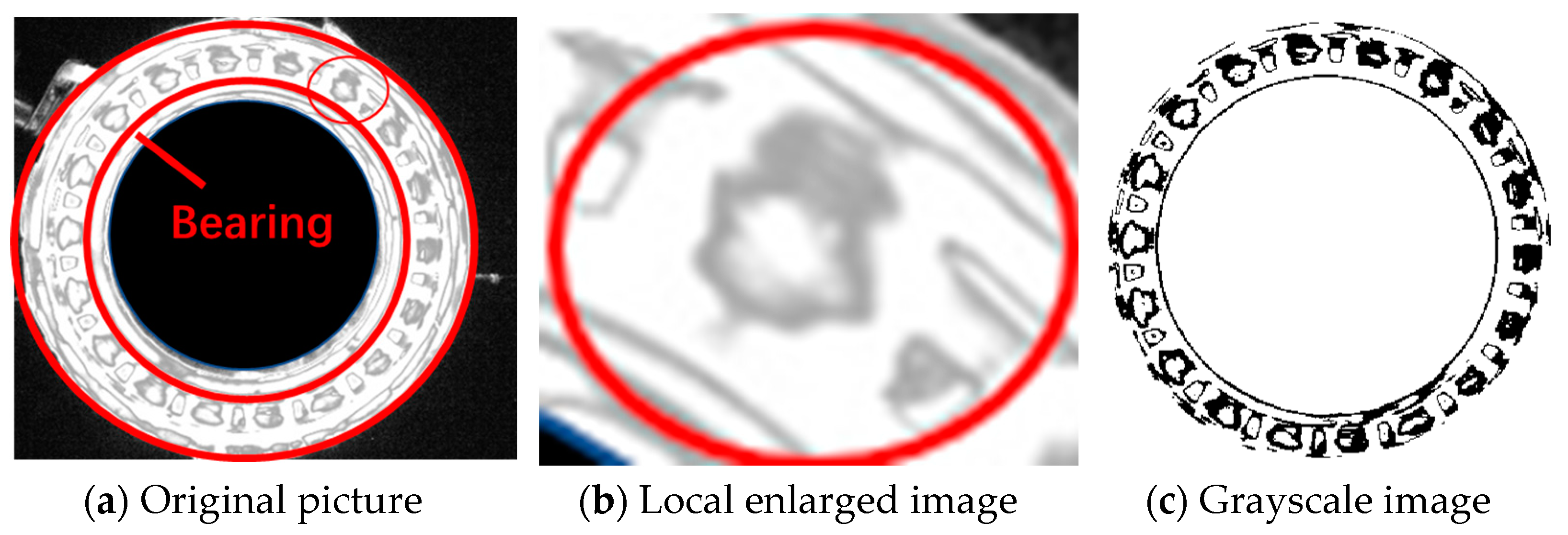
A high-speed camera with a resolution of 640 × 370, frame rate of 1000, and exposure time of 0.5 ms was adopted. Given the operation speed of 1000 r/min, repetitive tests for lubrication were carried out. Pictures of the tested bearing were taken; the original picture when t = 60.0002 s is shown in Figure 5a, and its local enlarged image and grayscale image are shown in Figure 5b,c. During operation, the lubricant with black ink tracer material in the internal clearance of the bearing produced shadows, which could be captured in the pictures through the transparent bearing. So, the shaded part in the image denotes the lubricant and clearly represents its distribution in the tested bearing.
The pixel points were extracted from the obtained grayscale image with the OTSU method [31], which is a common and efficient image segmentation algorithm. The pixels of the given picture are represented in L gray levels. The number of pixels at level i is denoted by ni, and the total number of pixels by N = n1 + … + nL. The gray-level histogram is regarded as a probability distribution:
P i = i = 1 L n i / N
The pixels are dichotomized into two classes, i.e., targets (lubricant oil) and backgrounds, by a threshold at level t. The between-class variance σ 2 , which is used for the criterion measurement to obtain the optimization segmentation threshold, can be expressed by
σ 2 = q 1 [ 1 q 1 ] [ μ 1 μ 2 ] 2
where q1 and u1 denote the probability and mean value of the target class with gray levels [1,…,t], respectively, and u2 denotes the mean value of the background class with gray levels [t + 1,…,L], given by
q 1 = i = 1 t P i
μ 1 = i = 1 t i P i / q 1
μ 2 = i = t + 1 L i P i / ( 1 q 1 )
The optimal threshold of gray level t* for extracting targets from their background can be sought by maximizing the between-class variance σ 2 in Formula (2). After that, it is easy to obtain the number of pixels for the target class (lubricant in bearing) as follows:
P = i = 1 t n i
The calculated pixel numbers can be used to quantitatively characterize the lubricant volume in the bearing. The more pixels there are, the more lubricant there is in the bearing.
To verify its repeatability, repeated tests in the same working conditions as described above were carried out three times, and the corresponding statistics were made. The pixel numbers for the lubricant in the bearing at the three different times are 9485, 8953, and 9970, of which the maximum difference is less than 1100. So, the measurements have adequate repeatability and meet the test requirements.

3. Influence of Lubrication Conditions on Lubricant Distribution

In order to analyze the influence of oil jet nozzle angles on lubrication characteristics, five operating conditions listed in Table 2 were adopted, in which the angle between the nozzle and the axial plane of the bearing was adjusted to 20°, 30°, 40°, 50°, and 60°, respectively, as shown in Figure 2. With the operation speed of 400 r/min and the height of the injection point of 44.7 mm, measurements of lubrication were carried out.

3.1. Influence of Oil Jet Nozzle Angle on Lubricant Distribution

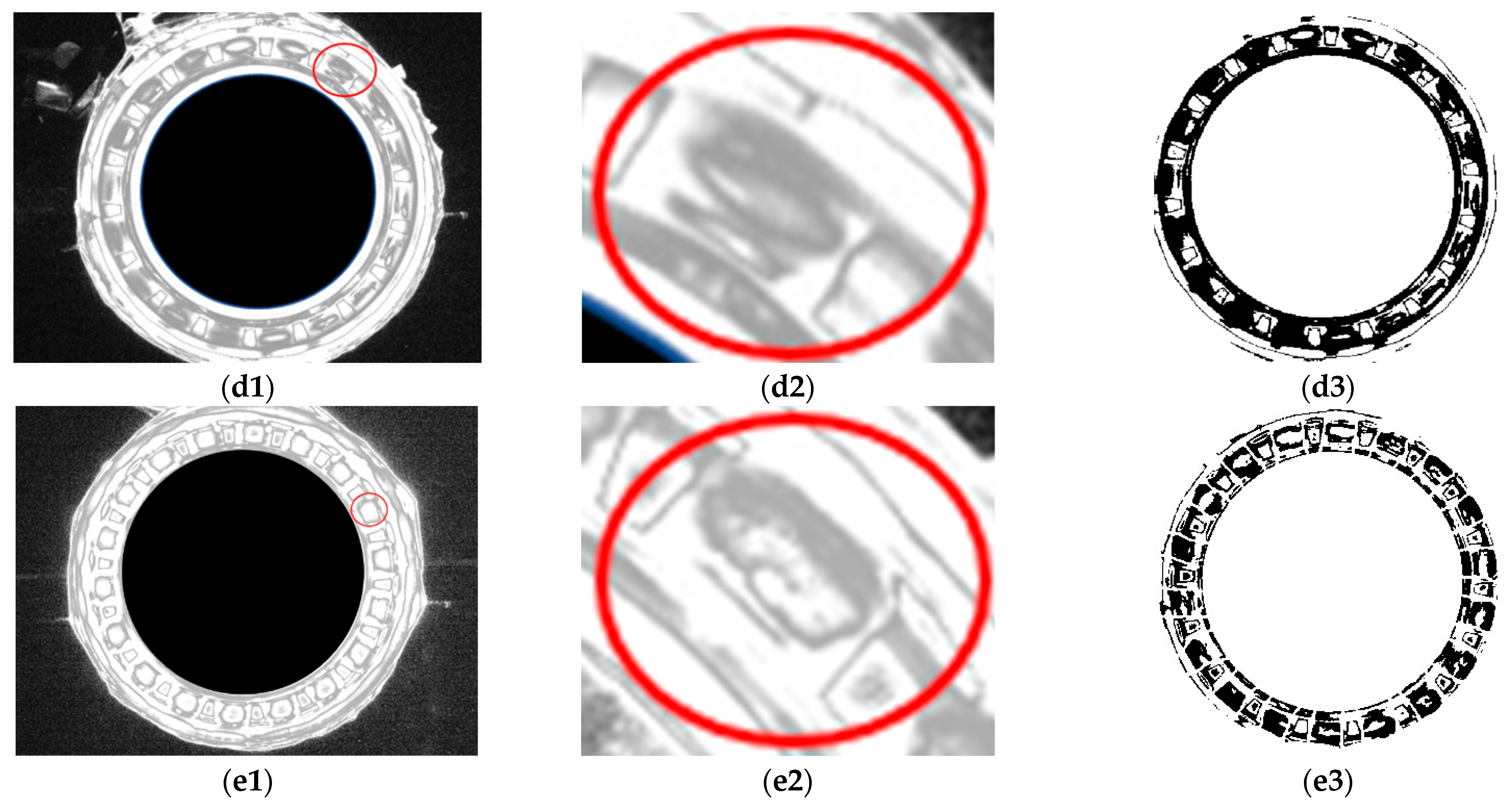
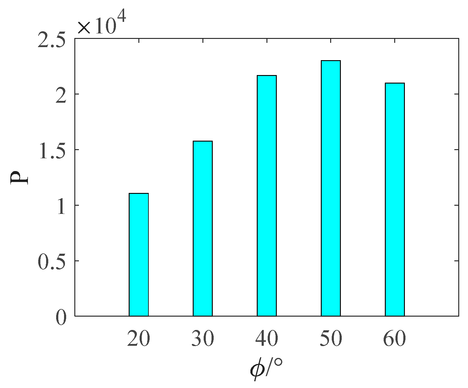
The original pictures, local enlarged images, and grayscale images of the lubricant under the five different operating conditions listed in Table 2 are shown in Figure 6. The pixel numbers of oil in the grayscale images under the five conditions were calculated and are illustrated in Figure 7, and can be helpful to quantitatively analyze the influence of nozzle angle on the lubricant distribution.
It can be clearly seen from Figure 6 and Figure 7 that when the nozzle angle is 20°, the amount of lubricant in the bearing is the least, and the distribution is unbalanced. The increasing trend of oil volume is obvious with the increment in nozzle angle. The larger nozzle angle is beneficial for oil injection and useful to provide a more uniform oil distribution. Nevertheless, too large a nozzle angle is unfavorable for oil entering the internal clearance of the bearing. The pixel numbers of the lubricant when the nozzle angle is 60° are lower compared with those when the nozzle angle is 50° for the tested bearing. The optimal nozzle angle is available for bearing lubrication, and should be given sufficient consideration in identifying suitable lubricants.

3.2. Influence of Operating Speed on Lubricant Distribution

In order to analyze the influence of operating speeds on lubrication characteristics, four operating conditions listed in Table 3 were adopted, in which the operating speed was adjusted to 300, 600, 900, and 1200 r/min. With a nozzle angle of 20° and height of the injection point of 44.7 mm, the tests were carried out.
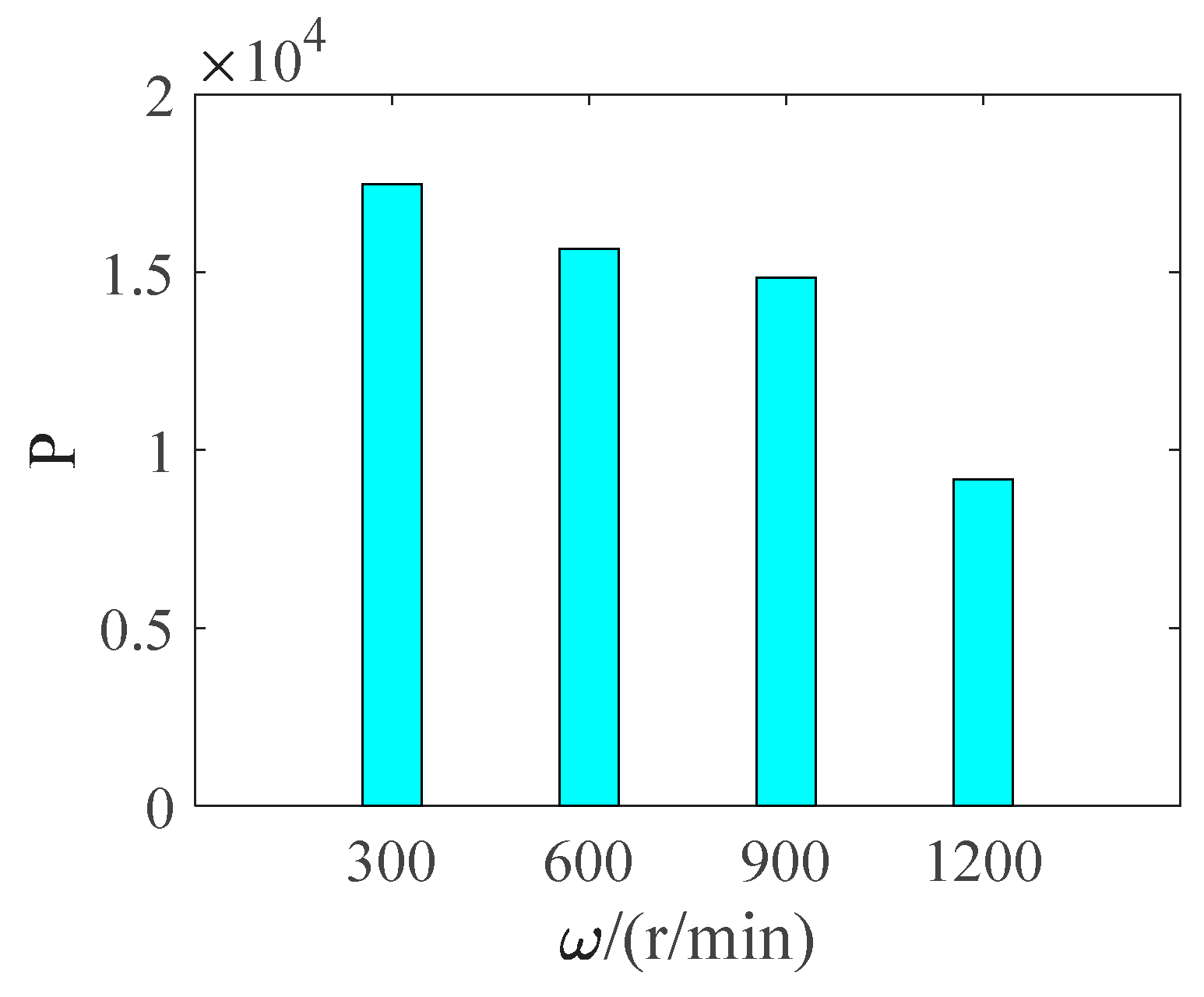
The original pictures, local enlarged images, and grayscale images of the lubricant in the bearing at four different speeds are illustrated in Figure 8. The pixel numbers of the lubricant under the corresponding conditions were calculated and are illustrated in Figure 9.
It can be clearly seen from Figure 8 and Figure 9 that with the increment in operating speed, the oil volume in the bearing obviously decreases. With the operating speeds ranging from 300 r/min to 1200 r/min, the pixel numbers of the lubricant decrease evidently. Because a higher speed can result in higher centrifugal force for the roller and cage, and even the lubrication oil, the lubrication oil will easily be rebounded and thrown out of the bearing chamber, which will induce the starved lubrication state at a high speed.

4. Influence of Cage Structure on Lubricant Distribution

The lubrication groove structure in the cage surface is commonly designed to improve the lubrication performance of bearings, as shown in Figure 10.
In order to analyze the influence of cage groove structure on lubrication characteristics, three cases listed in Table 4 were adopted, in which the radius of groove R was adjusted to 0, 4.5, and 4.5 mm, with corresponding groove depths of 0, 0.66, and 1.25 mm, respectively, as shown in Figure 11. With a nozzle angle of 20°, height of injection point of 37.2 mm, and operating speed of 1000 r/min, the tests were carried out.
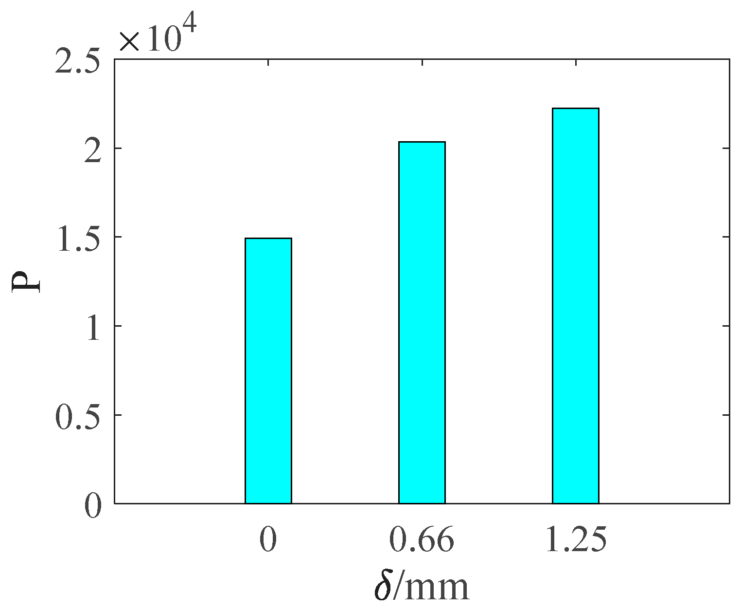
The original pictures, local enlarged images, and grayscale images of the lubricant under the three different cases listed in Table 4 are illustrated in Figure 12. The pixel numbers of lubrication oil under the corresponding conditions were calculated and are illustrated in Figure 13.
It can be clearly seen from Figure 12 and Figure 13 that the lubrication oil volume for the bearing with the cage groove structure increased significantly compared to that of the bearing without the groove structure. With the depth of cage grooves ranging from 0 mm to 1.25 mm, the pixel numbers of lubrication oil increase obviously, indicating that the oil volume in the bearing cavity keeps increasing with the depth of the cage grooves.
The cage grooves on a cage guiding surface coinciding with an oil jet nozzle angle will allow more lubricant to enter the lubricating oil grooves on the guiding surface of the cage. Further, the lubricant in grooves will transfer to other internal clearance positions along with bearing rotation. Larger cage grooves can be useful to save more lubrication oil. Then, there are more opportunities for lubrication oil to enter the bearing’s internal area. Therefore, the structural design of the cage groove has important significance for improving bearing lubrication.

5. Conclusions

In this paper, a measurement system for lubricant distribution was specifically established to obtain original pictures and grayscale images of the lubricant by picture processing to characterize the lubricant distribution and lubricant volume in bearings. Measurements of the lubricant distribution in angular ball bearings were carried out under different lubrication and cage groove conditions, and their influences were investigated. The conclusions were drawn as follows:
(1)
The observation of lubricant distribution based on a specially designed test rig was proposed, and pixel numbers of the lubricant can be calculated to quantitatively characterize the oil volume in a bearing.
(2)
The lubricant distribution is affected by the oil jet nozzle angle, operating speed, and cage structure. The lubricant distributed among balls and the cage pocket in bearings gradually increased with the increase in the nozzle angle, but decreased with the rising operating speed. The optimal nozzle angle available for lubrication needs to be given sufficient consideration.
(3)
The structure of cage grooves can significantly affect the lubricant distribution inside the bearing. The increase in the depth of cage grooves caused an increase in lubrication capacity in the bearing. With the increased depth of cage grooves, the oil volume in the bearing cavity keeps increasing, which is more favorable for the lubricant distribution in bearings. Therefore, the structural design of cage grooves has important significance for improving bearing lubrication.

Author Contributions

Methodology and original manuscript B.W.; experimental data Y.L.; ideas, investigation, funding acquisition, M.W.; experimental recommend, Y.Y. All authors have read and agreed to the published version of the manuscript.

Funding

This work was supported by the National Natural Science Foundation of China (grant no. 51905069), the Innovation Ability Improvement Project for Small and Medium-sized Scientific and Technological Enterprise of Shandong Province (grant no. 2021TSGC1328), and the Basic Scientific Research Project the of Education Department of Liaoning Province (grant no. LJKZ0536 and grant no. LJKMZ20220864).

Institutional Review Board Statement

Not applicable for studies not involving humans or animals.

Informed Consent Statement

Informed consent was obtained from all subjects involved in the study.

Data Availability Statement

Not Applicable.

Conflicts of Interest

The authors declare no conflict of interest.

References

  1. Gao, W.; Nelias, D.; Li, K.; Liu, Z.; Lyu, Y. A multiphase computational study of oil distribution inside roller bearings with under-race lubrication. Tribol. Int. 2019, 140, 105862. [Google Scholar] [CrossRef]
  2. Jiang, L.; Lyu, Y.; Gao, W.; Zhu, P.; Liu, Z. Numerical investigation of the oil–air distribution inside ball bearings with under-race lubrication. Proc. Inst. Mech. Eng. Part J J. Eng. Tribol. 2022, 236, 499–513. [Google Scholar] [CrossRef]
  3. Yunlong, W.; Wenzhong, W.; Yulong, L.; Ziqiang, Z. Lubrication and thermal failure mechanism analysis in high-speed angular contact ball bearing. J. Tribol. 2018, 140, 031503. [Google Scholar] [CrossRef]
  4. Russell, T.; Sadeghi, F. The Effects of Lubricant Starvation on Ball Bearing Cage Pocket Friction. Tribol. Int. 2022, 173, 107630. [Google Scholar] [CrossRef]
  5. Zhirkin, Y.V.; Puzik, E.; Sultanov, N. Design of heavy-duty bearings with oil–air lubrication. Russ. Eng. Res. 2016, 36, 1001–1003. [Google Scholar] [CrossRef]
  6. Ge, L.; Wang, C.; Yan, K.; Zhu, Y.; Hong, J. Design of groove structures for bearing lubrication enhancement based on the flow mechanism analysis. Tribol. Int. 2021, 158, 106950. [Google Scholar] [CrossRef]
  7. Wen, B.; Wang, M.; Zhang, X.; Zhai, J.; Sun, W. Experimental Investigation of Clearance Influences on Cage Motion and Wear in Ball Bearings. Appl. Sci. 2021, 11, 11848. [Google Scholar] [CrossRef]
  8. Damiens, B.; Lubrecht, A.; Cann, P. Influence of cage clearance on bearing lubrication©. Tribol. Trans. 2004, 47, 2–6. [Google Scholar] [CrossRef]
  9. Liu, J.; Ni, H.; Zhou, R.; Li, X.; Xing, Q.; Pan, G. A simulation analysis of ball bearing lubrication characteristics considering the cage clearance. J. Tribol. 2023, 145, 044301. [Google Scholar] [CrossRef]
  10. Oh, I.-S.; Kim, D.; Hong, S.-W.; Kim, K. Three-dimensional air flow patterns within a rotating ball bearing. Adv. Sci. Lett. 2013, 19, 2180–2183. [Google Scholar] [CrossRef]
  11. Yan, K.; Wang, Y.; Zhu, Y.; Hong, J.; Zhai, Q. Investigation on heat dissipation characteristic of ball bearing cage and inside cavity at ultra high rotation speed. Tribol. Int. 2016, 93, 470–481. [Google Scholar] [CrossRef]
  12. Yan, B.; Dong, L.; Yan, K.; Chen, F.; Zhu, Y.; Wang, D. Effects of oil-air lubrication methods on the internal fluid flow and heat dissipation of high-speed ball bearings. Mech. Syst. Signal Process. 2021, 151, 107409. [Google Scholar] [CrossRef]
  13. Liu, J.; Ni, H.; Xu, Z.; Pan, G. A simulation analysis for lubricating characteristics of an oil-jet lubricated ball bearing. Simul. Model. Pract. Theory 2021, 113, 102371. [Google Scholar] [CrossRef]
  14. Peterson, W.; Russell, T.; Sadeghi, F.; Berhan, M.T. Experimental and analytical investigation of fluid drag losses in rolling element bearings. Tribol. Int. 2021, 161, 107106. [Google Scholar] [CrossRef]
  15. Peterson, W.; Russell, T.; Sadeghi, F.; Berhan, M.T.; Stacke, L.-E.; Ståhl, J. A CFD investigation of lubricant flow in deep groove ball bearings. Tribol. Int. 2021, 154, 106735. [Google Scholar] [CrossRef]
  16. Wu, W.; Hu, C.; Hu, J.; Yuan, S. Jet cooling for rolling bearings: Flow visualization and temperature distribution. Appl. Therm. Eng. 2016, 105, 217–224. [Google Scholar] [CrossRef]
  17. Wu, W.; Hu, J.; Yuan, S.; Hu, C. Numerical and experimental investigation of the stratified air-oil flow inside ball bearings. Int. J. Heat Mass Transf. 2016, 103, 619–626. [Google Scholar] [CrossRef]
  18. Hu, J.; Wu, W.; Wu, M.; Yuan, S. Numerical investigation of the air–oil two-phase flow inside an oil-jet lubricated ball bearing. Int. J. Heat Mass Transf. 2014, 68, 85–93. [Google Scholar] [CrossRef]
  19. Ma, F.; Jiang, F.; Qi, A. Simulation of hydrodynamic lubrication between cage pockets and rollers in cylindrical roller bearings. Proc. Inst. Mech. Eng. Part C J. Mech. Eng. Sci. 2015, 229, 2551–2560. [Google Scholar] [CrossRef]
  20. Wu, C.-H.; Kung, Y.-T. A parametric study on oil/air lubrication of a high-speed spindle. Precis. Eng. 2005, 29, 162–167. [Google Scholar] [CrossRef]
  21. Aidarinis, J.; Missirlis, D.; Yakinthos, K.; Goulas, A. CFD modeling and LDA measurements for the air-flow in an aero engine front bearing chamber. J. Eng. Gas Turbines Power 2011, 133, 082504. [Google Scholar] [CrossRef]
  22. Chen, H.; Liang, H.; Wang, W.; Zhang, S. Investigation on the oil transfer behaviors and the air-oil interfacial flow patterns in a ball bearing under different capillary conditions. Friction 2023, 11, 228–245. [Google Scholar] [CrossRef]
  23. Sánchez-González, R.; North, S.W. Nitric oxide laser-induced fluorescence imaging methods and their application to study high-speed flows. In Frontiers and Advances in Molecular Spectroscopy; Elsevier: Amsterdam, The Netherlands, 2018; pp. 599–630. [Google Scholar]
  24. Meinhart, C.D.; Wereley, S.T.; Santiago, J.G. PIV measurements of a microchannel flow. Exp. Fluids 1999, 27, 414–419. [Google Scholar] [CrossRef]
  25. Mastrone, M.N.; Hartono, E.A.; Chernoray, V.; Concli, F. Oil distribution and churning losses of gearboxes: Experimental and numerical analysis. Tribol. Int. 2020, 151, 106496. [Google Scholar] [CrossRef]
  26. Maccioni, L.; Chernoray, V.G.; Bohnert, C.; Concli, F. Particle Image Velocimetry measurements inside a tapered roller bearing with an outer ring made of sapphire: Design and operation of an innovative test rig. Tribol. Int. 2022, 165, 107313. [Google Scholar] [CrossRef]
  27. Maccioni, L.; Chernoray, V.G.; Mastrone, M.N.; Bohnert, C.; Concli, F. Study of the impact of aeration on the lubricant behavior in a tapered roller bearing: Innovative numerical modelling and validation via particle image velocimetry. Tribol. Int. 2022, 165, 107301. [Google Scholar] [CrossRef]
  28. Arya, U.; Peterson, W.; Sadeghi, F.; Meinel, A.; Grillenberger, H. Investigation of oil flow in a ball bearing using Bubble Image Velocimetry and CFD modeling. Tribol. Int. 2023, 177, 107968. [Google Scholar] [CrossRef]
  29. Chen, H.; Wang, W.; Liang, H.; Ge, X. Observation of the oil flow in a ball bearing with a novel experiment method and simulation. Tribol. Int. 2022, 174, 107731. [Google Scholar] [CrossRef]
  30. Liang, H.; Zhang, Y.; Wang, W. Influence of the cage on the migration and distribution of lubricating oil inside a ball bearing. Friction 2022, 10, 1035–1045. [Google Scholar] [CrossRef]
  31. Otsu, N. A threshold selection method from gray-level histograms. IEEE Trans. Syst. Man Cybern. 1979, 9, 62–66. [Google Scholar] [CrossRef] [Green Version]
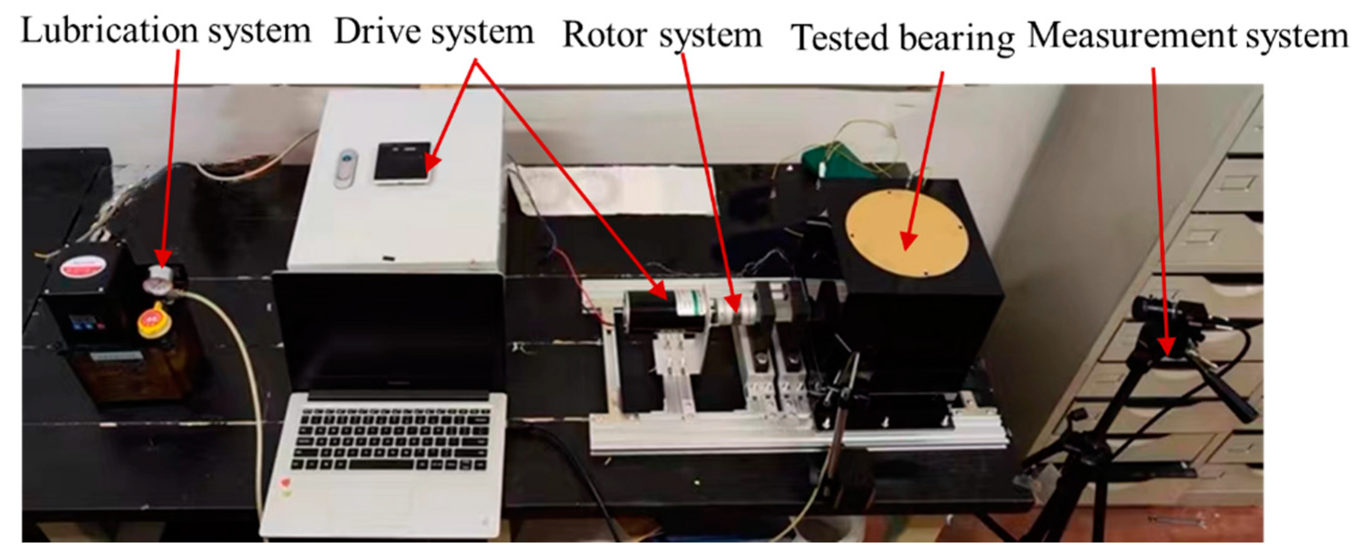
Figure 1. Test rig.
Figure 1. Test rig.
Lubricants 11 00063 g001
Figure 2. Sketch and photos of measurement system.
Lubricants 11 00063 g002
Figure 3. Tested transparent bearing.
Lubricants 11 00063 g003
Figure 4. Transparent rotor.
Lubricants 11 00063 g004
Figure 5. The result of photographing the oil sprayed at a nozzle angle of 20 degrees.
Lubricants 11 00063 g005
Figure 6. Original pictures (a1,b1,c1,d1,e1), local enlarged images (a2,b2,c2,d2,e2), and grayscale images (a3,b3,c3,d3,e3) of the lubricant with five different nozzle angles: (a1a3) 20°, (b1b3) 30°, (c1c3) 40°, (d1d3) 50°, (e1e3) 60°.
Lubricants 11 00063 g006aLubricants 11 00063 g006b
Figure 7. Pixel numbers of lubricant in the grayscale images with five different nozzle angles.
Lubricants 11 00063 g007
Figure 8. Original pictures (a1,b1,c1,d1), local enlarged images (a2,b2,c2,d2), and grayscale images (a3,b3,c3,d3) of the lubricant at four different speeds: (a1a3) 300 r/min, (b1b3) 600 r/min, (c1c3) 900 r/min, (d1d3) 1200 r/min.
Lubricants 11 00063 g008aLubricants 11 00063 g008b
Figure 9. Pixel numbers of lubricant in the grayscale images at four different speeds.
Lubricants 11 00063 g009
Figure 10. Schematic diagram of the cage with lubrication groove structure.
Lubricants 11 00063 g010
Figure 11. Photos of cage with different groove structures.
Lubricants 11 00063 g011
Figure 12. Original pictures (a1,b1,c1), local enlarged images (a2,b2,c2), and grayscale images (a3,b3,c3) of the lubricant with three different groove structures: (a1a3) case 1, (b1b3) case 2, (c1c3) case 3.
Lubricants 11 00063 g012aLubricants 11 00063 g012b
Figure 13. Pixel numbers of lubricant in the grayscale images with three different groove structures.
Lubricants 11 00063 g013
Table 1. Structural parameters of the tested bearing.
ItemSymbolUnitValue
Diameter of inner ringdmm65
Diameter of outer ringDmm100
Groove curvature coefficient of inner ring f i 0.515
Groove curvature coefficient of outer ring f 0 0.525
Diameter of ballDwmm11
Number of ballsZNo.18
Contact angleα°15
Width of ringBmm18
Table 2. Operating conditions with different nozzle angles.
CasesOil Jet Nozzle Angles (°)Height of the Injection Point (mm)Operation Speed (r/min)Test Results
Case 12044.7400Figure 6(a1–a3)
Case 23044.7400Figure 6(b1–b3)
Case 34044.7400Figure 6(c1–c3)
Case 45044.7400Figure 6(d1–d3)
Case 56044.7400Figure 6(e1–e3)
Table 3. Operating conditions at different operation speeds.
CasesOil Jet Nozzle Angles (°)Height of the Injection Point (mm)Operating Speed (r/min)Test Results
Case 12044.7300Figure 8(a1–a3)
Case 22044.7600Figure 8(b1–b3)
Case 32044.7900Figure 8(c1–c3)
Case 42044.71200Figure 8(d1–d3)
Table 4. Operating conditions with three different groove structures.
CasesRadius and Depth of Groove (mm)Oil Jet Nozzle Angles (°)Height of the Injection Point (mm)Operating Speed (r/min)Test Results
Case 10, 0037.21000Figure 12(a1–a3)
Case 24.5, 0.66037.21000Figure 12(b1–b3)
Case 34.5, 1.25037.21000Figure 12(c1–c3)
Disclaimer/Publisher’s Note: The statements, opinions and data contained in all publications are solely those of the individual author(s) and contributor(s) and not of MDPI and/or the editor(s). MDPI and/or the editor(s) disclaim responsibility for any injury to people or property resulting from any ideas, methods, instructions or products referred to in the content.