Article

Oil–Air Two-Phase Flow Distribution Characteristics inside Cylindrical Roller Bearing with Under-Race Lubrication

School of Power and Energy, Northwestern Polytechnical University, Xi’an 710072, China
*
Author to whom correspondence should be addressed.
Lubricants 2024, 12(4), 133; https://doi.org/10.3390/lubricants12040133
Submission received: 3 February 2024 / Revised: 28 March 2024 / Accepted: 1 April 2024 / Published: 16 April 2024
(This article belongs to the Special Issue Tribological Study in Rolling Bearing)

Abstract

:
A deep understanding of oil behavior inside roller bearings is important for the precise design of bearing configurations and oil systems in aircraft engines. The numerical method is employed to track oil distribution inside cylindrical roller bearings with under-race lubrication along the circumference and radial direction, respectively. The results demonstrate that oil distribution along the circumference is periodic with the number of under-race nozzles, and higher rotating speed and lower flow rate would reduce the fluctuation amplitude. It is difficult for oil to flow through the gap between the cage pocket and rollers, and higher oil viscosity would worsen it further. In some extreme cases, the oil volume fraction near the outer race may be lower than 0.7%, causing the risk of lubricating and cooling failure. Thus, more attention should be paid to the outer race of the roller bearing with under-race lubrication, especially during the starting stage of the engine and in cold weather.

1. Introduction

High-speed cylindrical roller bearing plays an important role in aircraft engines, such as supporting the engine’s main-shaft rotors in the turbine region [1], as the bearing can withstand a bit of axial displacement or deformation. Considering its high rotating speed and high-temperature environment, a good lubrication state is a key factor for the bearing to maintain stable and long-term operation. Under-race lubrication is now increasingly employed for main-shaft roller bearings in modern gas turbine engines [2,3]. Different from traditional jet lubrication with one or several fixed nozzles outside the bearing, in under-race lubrication bearing, the oil is thrown into the bearing cavity by centrifugal force caused by a high-speed rotating shaft, through radial hollows in the inner ring [4]. The oil injection direction, position, and velocity are all changed totally. Benefiting from several hollows through the inner ring, the oil enters the bearing cavity radially and reaches the roller-ring contact zone directly. Accordingly, under-race lubrication can greatly improve lubrication and cooling effects and meet the stringent requirements of rolling bearing with DN > 3.0 × 10⁶ (Bearing diameter (mm) × Rotating speed (rpm)). Furthermore, it can also enhance inner-ring cooling, reduce cage skidding, and improve the bearing life [5]. However, oil flow velocity is a combination of radial injection speed and circumferential inner-ring rotating speed. This makes it much easier for the oil to escape from the bearing cavity, and the cooling effect for the outer ring may decrease. Understanding the oil behavior inside the bearing cavity with under-race lubrication is very important for future improvements of the lubrication system and bearing structure design [6,7,8].
Primarily, NASA carried out some experimental studies on ball bearings with jet lubrication [9], and Parker derived an equation for the oil volume fraction in the bearing cavity XCAV based on these experimental results, which is a function of lubricant flow rate, shaft speed, and bearing pitch diameter [10]. After that, Gabriel et al. [11] modified the original Parker formula, considering the oil supply method. The absolute cage speed is replaced with the relative speed between the inner ring and the cage if the lubricant is provided through the inner ring. But the oil volume fraction from the Parker formula is not reliable enough because it is deduced from thermal experiments rather than direct oil–air measurements, which is quite difficult in the complicated rotating roller bearing [10]. This basic problem means that Gabriel’s formula is not reliable enough.
Observing oil flow characteristics or oil distribution inside a high-speed rotating roller bearing is nearly impossible, in view of the complicated internal geometry of the bearing and the operating environment. The computational fluid dynamics (CFD) method is now an alternative method to obtain oil–air two-phase flow inside rolling bearings [12,13]. For the bearing with jet lubrication, Hu and Wu et al. [14] investigated the oil–air two-phase flow inside an angular contact ball bearing with oil jet lubrication by the VOF multiphase model. Yan et al. [15] used the CLSVOF method to track the oil–air interface inside the bearing cavity with oil–air lubrication. Zhang et al. [16] investigated the influence of jet velocity of oil-jet-lubricated ball bearings on the oil flow characteristics. Wu Wei et al. [17,18] investigated the flow characteristics inside a ball bearing with multiple nozzles for oil supply. The research showed that the number of nozzles should not exceed four; considering its impact on oil volume fraction and the complexity of the oil supply mechanism, Liu et al. [19] used the VOF method and MRF model to numerically calculate the flow characteristics of lubricated oil in the simplified model of high-speed angular contact ball bearings. The results show that choosing an appropriate injection angle can increase the oil volume fraction.
While for rolling bearings with under-race lubrication, extensive research has also been conducted on oil and air two-phase flow in bearings. Flouros [20] investigated the two-phase flow in the bearing with under-race lubrication. Visualization results from high-speed cameras showed that the lubricated oil left the bearing through the gap between the cage pocket and the outer ring. Akinola et al. [21] studied the behavior of the oil and air within the space bounded by the cage and inner race with the VOF method. Oil droplets exiting the bearing are also simulated transiently, and it is found that the exiting rate is directly proportional to the shaft speed and decreases with the oil inlet flow rate. Gao et al. [22] investigated oil distribution inside a roller bearing with under-race lubrication and discussed the effects of rotational speeds, oil inlet velocity, and viscosity by a numerical method. But in his numerical model, the under-race lubrication configuration is simplified to one hollow. Bao et al. [2] used numerical simulation methods to investigate the effects of bearing speed, oil inlet speed, and diameter of the oil feed hole on the distribution and volume fraction of oil inside the bearing. In addition, the coordinates and rotation axis of the spin of the rollers were calculated, and the influence of the spin of the rollers on the oil distribution and volume fraction was discussed. Bao et al. [23] employed a similar numerical method to track the oil–air two-phase flow inside the ball bearing with under-race lubrication and evaluated the influence of various factors on the oil volume fraction. Jiang et al. [24], considering the structure of the oil supply channel in the inner ring, investigated the effects of operating parameters and nozzle configuration on the distribution behavior of lubricant oil in the bearing. The results of the numerical simulation indicate that the surface of the bearing components was not completely covered with lubricating oil, and the extent of oil spreading on the outer race, cage, ball, and inner race decreased successively. By adjusting the oil nozzle structure, the volume fraction of lubricated oil inside the bearing can be optimized. Gong et al. [25] investigated the internal pressure field distribution, streamline distribution, and other flow properties for the different radial working clearances in the ball bearing with under-race lubrication. The distribution of the lubricated oil in the key areas, such as the cage pocket surface and the inner and outer ring surfaces, was discussed.
In summary, up to now, research on oil–air two-phase flow and distribution inside the bearing cavity has mostly focused on ball bearings with jet lubrication, while several scholars have investigated ball bearings with under-race lubrication. On the contrary, investigation on cylindrical roller bearings with under-race lubrication is almost not regarded, and oil–air two-phase flow mechanism inside the bearing cavity is not yet clear. This is key for the precise design of the bearing and for improving the performance of the lubrication system. Therefore, based on the above literature and analysis, in this article, a CFD modeling method is presented for capturing oil–air two-phase flow and distribution inside cylindrical roller bearing with under-race lubrication, to increase the understanding of oil behavior and distribution after entering the bearing.

2. Cylindrical Roller Bearing with Under-Race Lubrication

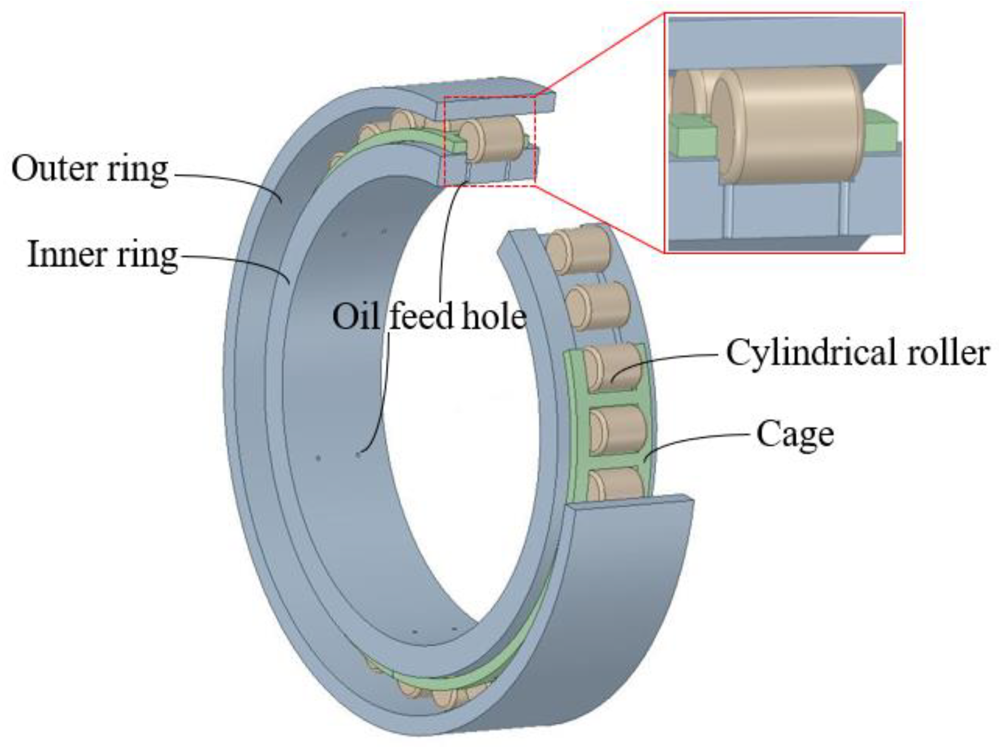
2.1. Geometric Configuration

A schematic diagram of a cylindrical roller bearing with under-race lubrication is shown in Figure 1. The lubricant oil is first injected into oil scoop elements and then the captured oil is transferred to the inner race through several axial oil passages. Six pairs of radial holes are distributed uniformly in the inner race with 60 degrees apart from each other. In the roller bearing, each hollow is located near the guiding shoulder on the inner ring and points to the roller element’s end. Through these hollows, lubricant oil is supplied into the bearing cavity with centrifugal force formed by the high-speed rotating shaft. After lubricating and cooling the bearing, oil droplets escape out of the bearing from two annular gaps between two rings and the cage. The geometrical parameters of the bearing are listed in Table 1. In this article, the diameter of the roller is reduced to 96.6% of its original size, with a diameter of 11.6 mm, contributing to the clearance of 0.2 mm between the roller and the inner or outer race. This gap is empirical but it is sufficient for the improvement of mesh quality and the decrease of grid number. The gap between the roller and the cage is 0.42 mm, which is the same as the actual situation.

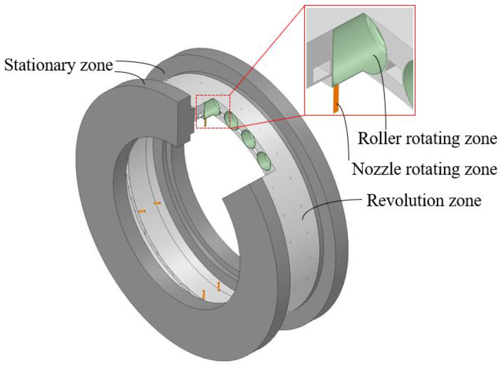
2.2. Calculation Domain

The computational fluid domain is presented in Figure 2, and solid structures of the bearing are all excluded. The fluid domain model contains four parts: the nozzle rotating zone, the roller rotating zone, the cage revolution zone, and the stationary zone. The nozzle rotating zone is the combination of 12 hollows in the inner ring, and it is the inlet for the lubricant oil entering the bearing. It rotates with the same rotating speed as the inner race. The roller rotating zone contains 28 cylindrical spaces, and each one deducts its enclosed corresponding roller element. The cylindrical space is concentric and coaxial with the enclosed element and is a little bigger in radius and length. The roller rotating zone is to imitate the roller’s rotating by its own axis, which determines oil flow and distribution significantly. The rotating speed of the rollers is given under ideal conditions without slipping:
n r = D m n i 2 D d [ 1 ( D d D m ) 2 ]
where n i is the rotating speed of the inner ring, rpm; Dd is the cylinder roller diameter, mm; Dm is the pitch diameter of the bearing.
Because only a little oil is located in the contact zone between the roller element and the raceway, the effect of lubricant oil film on oil–air distribution inside the bearing cavity is ignored. Furthermore, for the convenience of meshing, the clearance between the roller element and the raceway is magnified five times in the numerical model. The cage revolution zone is the circular space between the inner raceway and the outer raceway, deducting the cage and the roller rotating zone. Its rotating speed is equal to the cage’s rotating speed and is given as follows:
n m = n i 2 ( 1 D d D m )
The stationary zone is located on both sides of the bearing cavity to form appropriate outlet conditions. Considering that some escaping oil droplets may flow back into the bearing cavity, two annular chambers on the front and rear sides of the bearing are added, with two outlets away from the bearing [26]. In the bearing model, lubricant oil is supplied from 12 rotating holes in the inner race (the nozzle rotating zone), and then, the flow bypasses the roller rotating zone and the cage revolution zone. At last, the oil emerges from the bearing through outlets in the stationary zone.

3. Mathematical Modeling

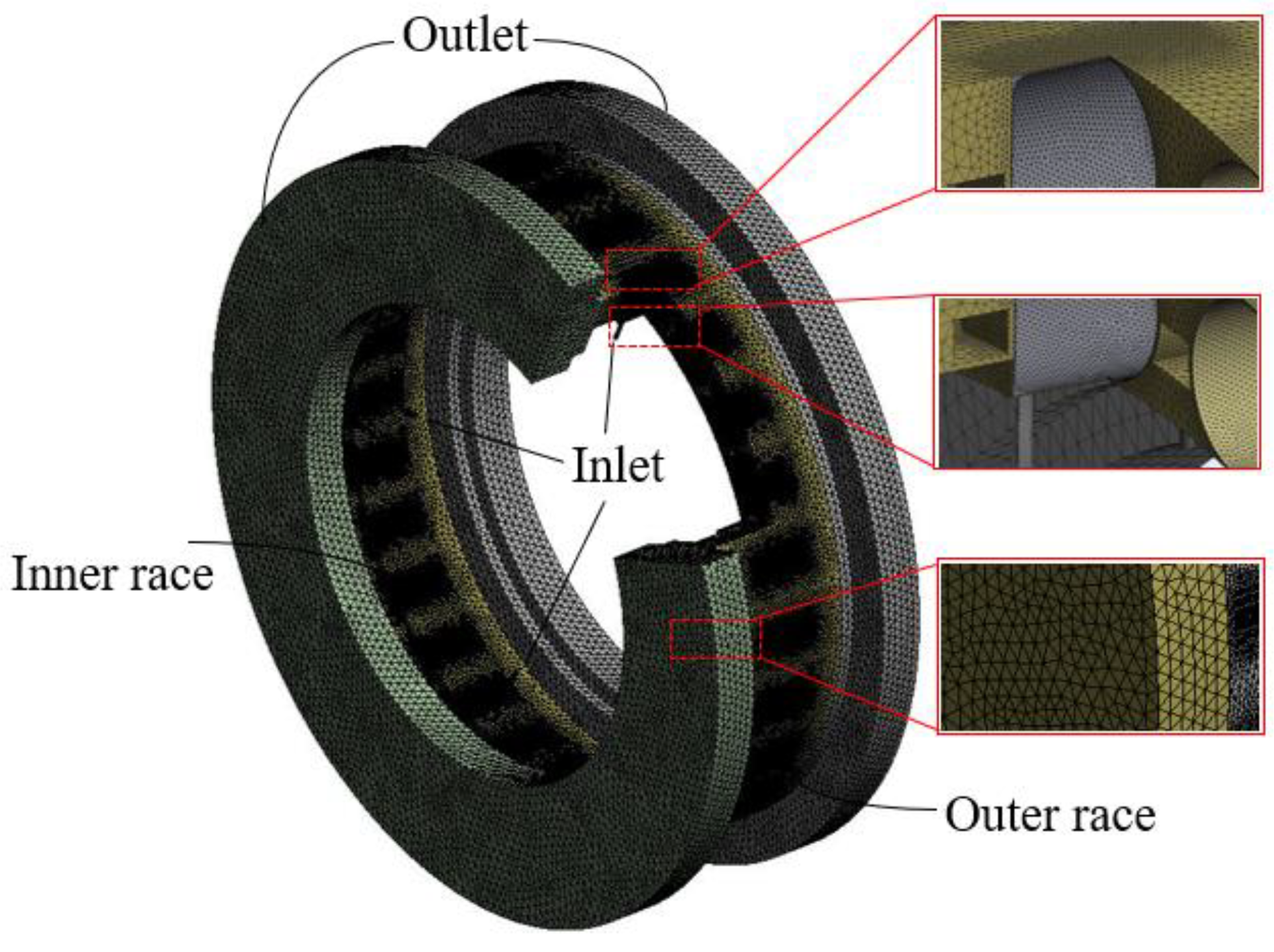
3.1. Meshing and Boundary Conditions

The flow domain is discretized with unstructured tetrahedral mesh in consideration of its complicated structure, except the inlet holes with structured hexahedral mesh, as shown in Figure 3. The grid element is refined in the roller rotating zone and contact regions between the roller and the raceway, to ensure high mesh quality. By changing global and local parameters, three sets of meshes are obtained. The average volume fraction of oil in the bearing is selected as the judgment basis for the inspection calculation, as shown in Table 2. After mesh independence verification, a mesh scheme with 3,779,748 elements and 953,836 nodes is finally adopted for the flow field. Considering the relative rotation between the inner ring, the cage, roller elements, and the surrounding space, interferences are formed between two adjacent zones. The sliding mesh is used at the edge of the inlet zone, the roller rotating zone, and the cage revolution zone.
In the numerical model, 12 holes in the inner race are set as mass flow inlet, and its value is determined by different operations. Both sides of the stationary zone are set as pressure outlets, and it is equal to the standard atmospheric pressure. The inner-ring raceway rotates with the revolution zone at the cage rotating speed. The standard wall function is applied for the near-wall boundary. All rotating and stationary walls are set as no-slip boundary conditions.
In all cases, the air phase is set as an incompressible ideal atmosphere. Thus, the density of the air phase is set to 1.225 kg/m3, and the dynamic viscosity is set to 1.7894 × 10⁻⁵ kg/(m·s). The MIL-L-23699-type lubricant oil is used in the simulation as the second phase, that is, the density of the oil phase is set to 938.6 kg/m3 and the dynamic viscosity is set to 4.61 × 10⁻³ kg/(m·s). Oil properties including oil viscosity and density are changed in the calculation to evaluate their effect.

3.2. Two-Phase Flow Model

To track oil–air two-phase flow and distribution inside cylindrical roller bearings with under-race lubrication, the coupled level set volume of fluid (CLSVOF) method as proposed and implemented in ANSYS Fluent is used in this article. The method allows for the interface between two or more immiscible fluids to be tracked by solving a set of momentum equations. A volume fraction a is used to define the a-phase volume fraction. That is, where the volume fraction is 1, the domain is completely filled with oil and if a = 0, it is completely air-filled. The free surface is in the region 0 < a < 1. The level set approach uses a smooth signed function, α, such that a zero level-set iso-surface represents the free surface, and a positive or negative level-set describes either phase of the mixture. The CLSVOF technology effectively takes advantage of the mass conservation of the VOF method and the sharp interface capturing of the CLS method [27].

3.3. Numerical Setup

Cylindrical roller bearing with under-race lubrication has a relatively high-velocity difference between different elements at high-speed rotating conditions, which leads to complex turbulent flow. The renormalization group (RNG) k-ε model is based on the instantaneous Navier–Stokes (N-S) equation using a mathematical “renormalization group” method, including the effect of swirl flow on turbulence [28]. The RNG k-ε model can improve the precision under rotational flow in consideration of the effects of high strain rate, large curvature overflow, and other factors, which is chosen for turbulence flow simulation in this article. For the initialization, the calculation domain is filled with the gas phase, and the oil volume fraction is set to 0. Air is set as an incompressible primary phase. The SIMPLE (Semi-Implicit Method for Pressure-Linked Equations) method is adopted for the coupling of pressure and velocity. The second-order upwind difference is adopted for the momentum terms, and the first-order upwind difference is adopted for turbulent kinetic energy and turbulent dissipation rate terms. The pressure is adopted for the PRESTO! (Pressure staggering option) format.
The mass flow difference between inlets and outlets is used to judge the calculation convergence, together with the monitored average oil volume fraction inside the bearing cavity. When the mass flow rate difference between inlets and outlets decreases to 1% of the inlet mass flow rate, and the average oil volume fraction in the bearing remains stable, the calculation could be considered to reach convergence. The convergence criterion for the residual of each velocity component, turbulent kinetic energy, and the VOF function is set to be 1.0 × 10⁻⁴, while the convergence criterion for the residual of the turbulent kinetic energy dissipation rate is set to 1.0 × 10⁻³. In view of the bearing rotating speed, the time step size is set to 5.0 × 10⁻⁵ s. The number of time steps is more than 2000, and the simulated physical time is longer than 0.1 s.

4. Results and Discussion

It is important to keep an appropriate volume fraction of lubricant oil in the bearing cavity, which has a great impact on bearing lubrication, load-independent power loss, and bearing cooling. It is also related to the engine’s oil system performance and bearing life. In general, a higher level of oil volume fraction inside the bearing cavity has an adverse effect on windage drag and churning resistance, whereas it is beneficial for heat diffusion. As a result, a balance between different factors should be considered in the bearing and oil system design, based on the predicted oil flow characteristics. From oil jet lubrication to under-race lubrication, oil inlet position, oil inlet velocity, and oil inject direction are all changed. Thus, oil distribution inside the cylindrical roller bearing is simulated and analyzed precisely.

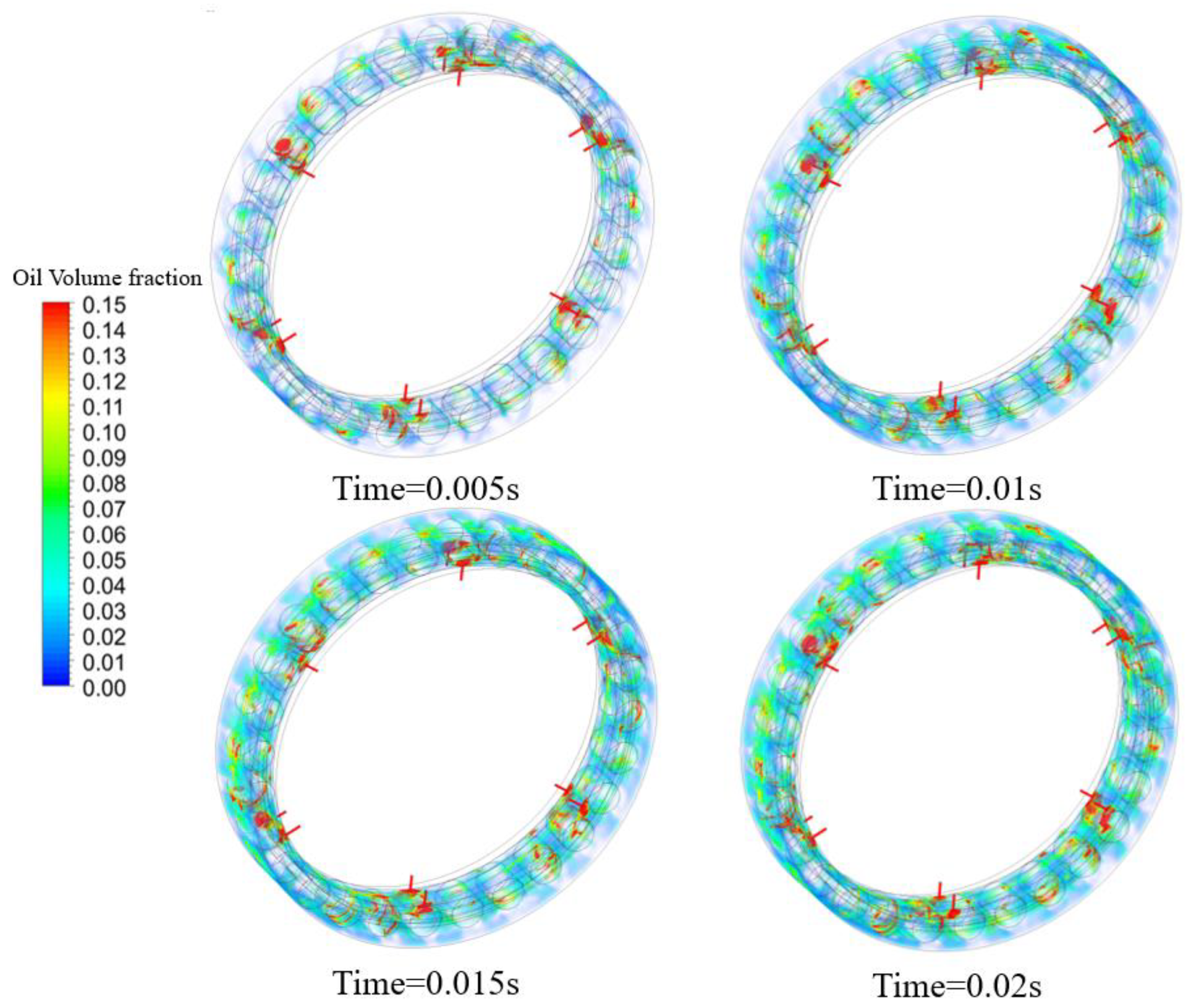
4.1. Nonuniform Oil Distribution in Bearing Cavity

In Figure 4, the oil accumulation process inside the bearing cavity is shown. The inner-ring rotating speed is 5000 rpm and the oil flow rate is 6.0 L/min. The oil dynamic viscosity is 4.61 × 10⁻³ kg/(m·s) and density is 938.6 kg/m3. It could be found that, with the oil supply and bearing rotation, the oil phase in the bearing cavity increases gradually and occupies the whole circumference very quickly. After 0.015 s, the inner ring rotates 1.25 circles and the oil distribution and the oil volume fraction change slightly. After 0.02 s, the oil distribution and the oil volume fraction maintain stability. In the following case, the simulation time is selected after 0.02 s to ensure the stability of the calculation results. Oil distribution inside the bearing cavity is not uniform so the region near the nozzle is much higher than other positions, which is illustrated clearly in Figure 5. Figure 5 and the following oil distribution figures are all from the cross-sectional slice of one group of inner-race nozzles, normal to the bearing shaft. Furthermore, it could be found that the oil phase is concentrated in the outer raceway and the gap between the cage and the inner race.
The streamline of the oil phase inside the bearing cavity is displayed in Figure 6. The lubricating oil enters between two adjacent rolling elements from the nozzle with greater velocity than the roller’s revolution speed. This leads oil moving forward to the front one and accumulating in the roller-ring contact zone. Oil flowing route is monitored during the simulation as illustrated in Figure 7, and the result illustrates that in the radial direction from the inner ring to the outer ring, 95.6% of the oil mass flow rate (m1) is from the gap between the cage pocket and roller and only 4.4% (m2) is from both sides of the cage. While for the route of oil leaving the bearing cavity, most of the oil (about 97.9%, m3) leaves the bearing from the gap between the cage and outer ring. It means that the gap is a key element to change the oil volume fraction inside the bearing.
In order to analyze the circumferential distribution of oil in the bearing, the bearing cavity is divided into 28 equal parts counterclockwise. The average volume fraction of oil in each part is collected. As shown in Figure 8, there are six peaks in the oil volume fraction distribution curve, along the circumference direction. This number is equal to under-race nozzle groups. The volume fraction of oil between two adjacent nozzles decreases obviously. As a result of the high inner-race rotating speed, the oil flows into the bearing cavity quickly and exits from the bearing very easily. Furthermore, the oil fraction in the upstream region of the nozzle changes steeply, which means that this position has not been affected by this nozzle. The oil fraction in the downstream region changes relatively slightly. To analyze the radial oil distribution in the bearing, the bearing cavity between the inner and outer raceways is cut into six parts in the radial direction. Every part is cut 2 mm along the radial direction, and the inner-ring raceway is designated as 0. The average volume fraction of oil in each part is collected as well. Figure 9 demonstrates the oil volume fraction in the radial direction. Most oil is resisted by the cage and stays in the gap between the cage and the inner raceway. Furthermore, some oil flows through the gap between rolling elements and the cage pocket and reaches the outer raceway as a result of centrifugal force and initial injecting kinetic energy, leading to the second oil-concentrated region.
Oil distribution along the circumference direction is different in different radial positions. The bearing cavity is divided into 5 parts radially, and each part is divided into 28 equal parts circumferentially. The average volume fraction of oil of each part is collected, as shown in Figure 10. In the gap between the cage and inner race, oil distribution variability is much more obvious caused by the inner-race nozzles. Lubricant oil first stays near the nozzle after injection into the bearing. In the region around the outer raceway, the oil is dispersed to become uniform by the rotating roller, rotating cage, and the relative rotation between the cage and inner race.

4.2. Working Condition Parameters Effects on Oil Distribution

The photographs of the flow pattern inside the bearing cavity at different inner-race rotating speeds are shown in Figure 11. The inner-ring rotating speed is 5000 rpm, 8000 rpm, 11,000 rpm, and 14,000 rpm, and the oil flow rate is 6.0 L/min. The oil dynamic viscosity is 4.61 × 10⁻³ kg/(m·s) and density is 938.6 kg/m3. It can be seen that the oil phase is almost located in the area of the outer race at 5000 rpm, and the oil-concentrated area near the nozzle is clear. With the inner-race rotating speed increasing, oil distribution becomes more uniform but declines. The average volume fraction of oil in the bearing under different working conditions is collected using the method described in Section 4.1. Figure 12 and Figure 13 confirm this trend in both the circumference direction and radial direction. With higher inner-race rotating speed, oil-received centrifugal force becomes bigger and its velocity becomes faster. It is much easier for oil to exit the bearing. In addition, the interaction between lubricant oil and bearing components is stronger, and this effect strengthens oil spreading in the bearing circle space. In the radial direction, the oil volume fraction around the inner raceway and outer raceway decreases with higher bearing rotating speed. But the position of the lowest points seems not changed and the lowest value is similar.
Oil volume flow rate is the other working condition parameter that determines oil–air two-phase flow inside the bearing cavity. As shown in Figure 14, the oil flow rate is from 2 L/min to 6 L/min. The inner-ring rotating speed is 5000 rpm, the oil dynamic viscosity is 4.61 × 10⁻³ kg/(m·s), and the density is 938.6 kg/m3. The flow pattern of oil distribution in the bearing is similar. Figure 15 and Figure 16 present oil distribution in two directions. It could be found that the difference between the nozzle field and the intermediate field becomes more significant with increasing oil flow rate, and more oil is kept in the gap between the cage and the inner raceway. That is, it is inefficient to enhance outer-race cooling by increasing the oil flow rate in under-race lubrication. Some innovative oil-supplying methods should be proposed to improve outer-race running conditions.

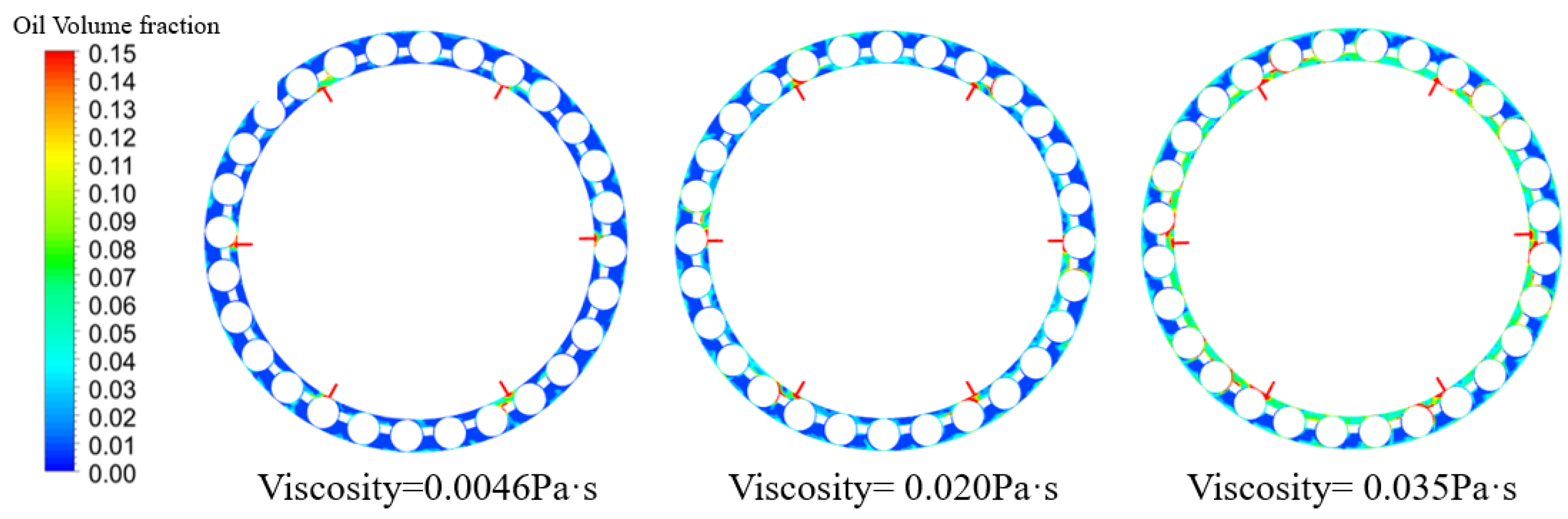
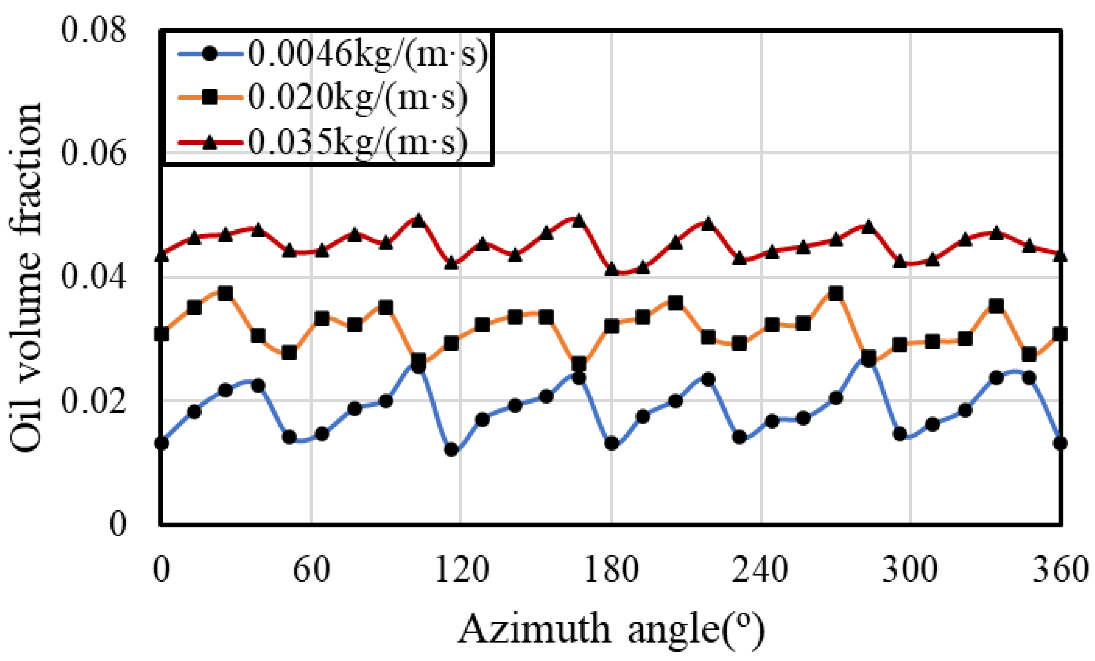
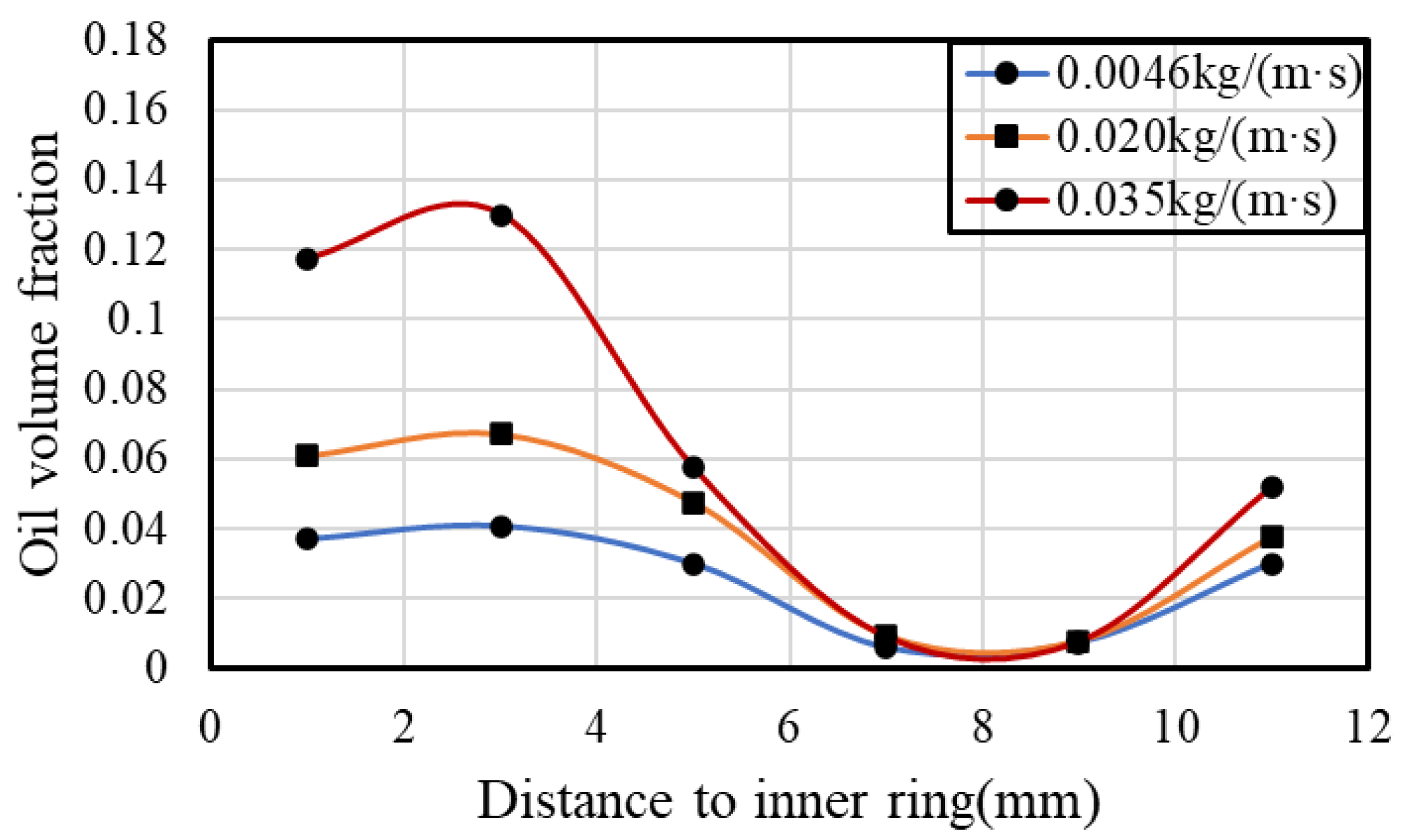
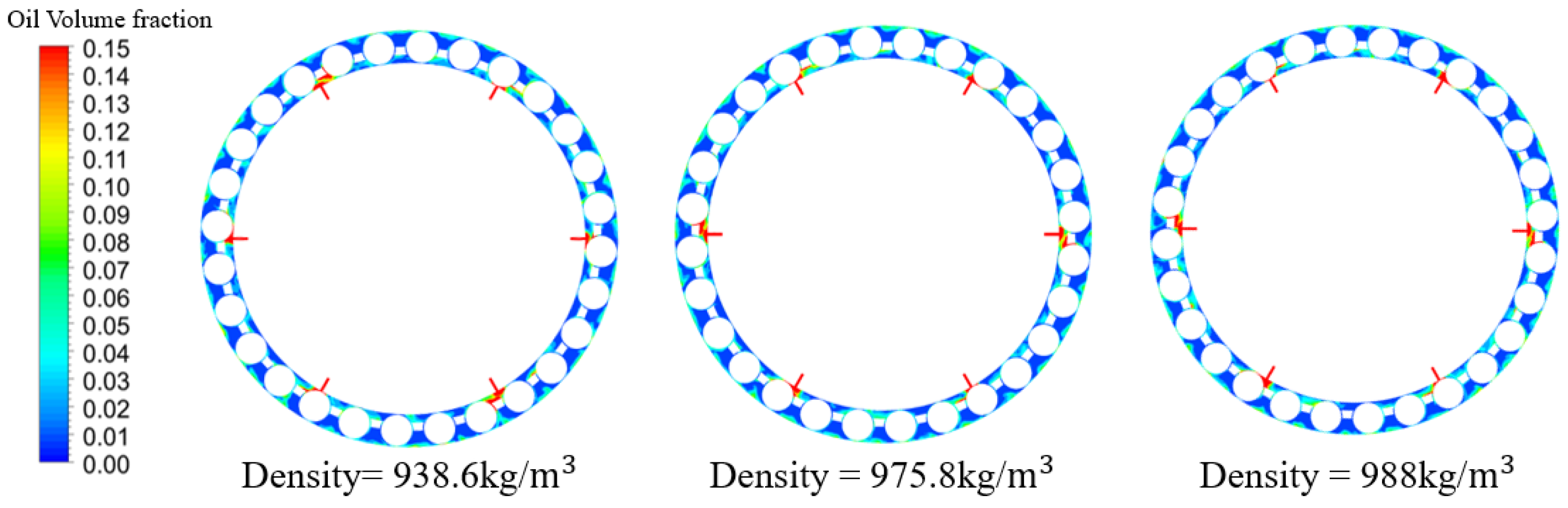
4.3. Oil Properties Effects on Oil Distribution

Fluid viscosity is one of the most important properties for lubricant oil to determine its lubrication performance, and it varies obviously with the oil type, temperature, and pressure [29]. As shown in Figure 17, the inner-ring rotating speed is 5000 rpm and the oil flow rate is 6 L/min. The oil dynamic viscosity is from 4.61 × 10⁻³ kg/(m·s) to 3.5 × 10⁻² kg/(m·s) and density is 938.6 kg/m3. It is illustrated in Figure 17 that the oil volume fraction inside the bearing cavity increases obviously with higher oil viscosity, especially the gap between the cage and inner race. Oil distribution along the circumference direction becomes more uniform, and the average oil volume fraction is also higher (as shown in Figure 18). But most oil is restricted in the region between the cage and inner race based on the result shown in Figure 19. It means that it is hard for the oil with higher viscosity to flow through the gap between the cage and the roller. Thus, during the engine’s starting stage or in a cold environment, more attention must be paid to the lubrication and cooling of the outer race.
During lubrication and cooling of the bearing, the oil would be heated, and its temperature may change visibly. Not only oil viscosity, but oil density will change. However, oil density changes slightly between different oil types or different temperatures. Figure 20, Figure 21 and Figure 22 show that the oil volume fraction inside the bearing cavity with different oil densities is almost the same. So that the effect of oil density on its distribution in the bearing could be generally ignored.

5. Conclusions

Investigation of oil–air two-phase flow characteristics inside rolling element bearing is of importance for its reliable lubrication and highly efficient cooling. In this article, a numerical model of one cylindrical roller bearing with under-race lubrication is built, and the computational fluid dynamics method is employed to simulate oil–air two-phase volume fraction distribution inside the bearing cavity, considering that direct experimental observation is quite difficult. Oil distribution along the circumference between the inner and outer race is studied with different operating conditions and lubricant properties.
(1)
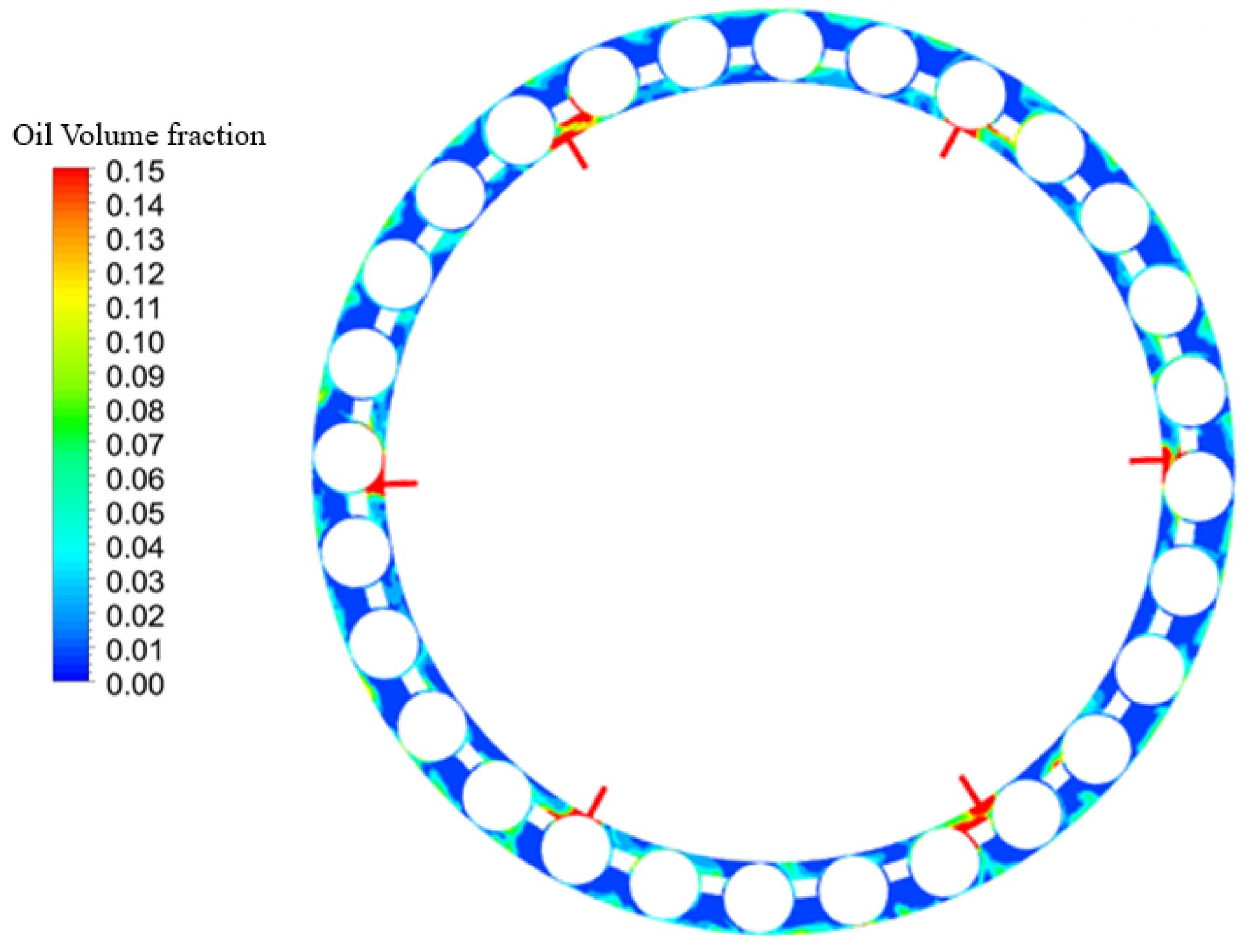
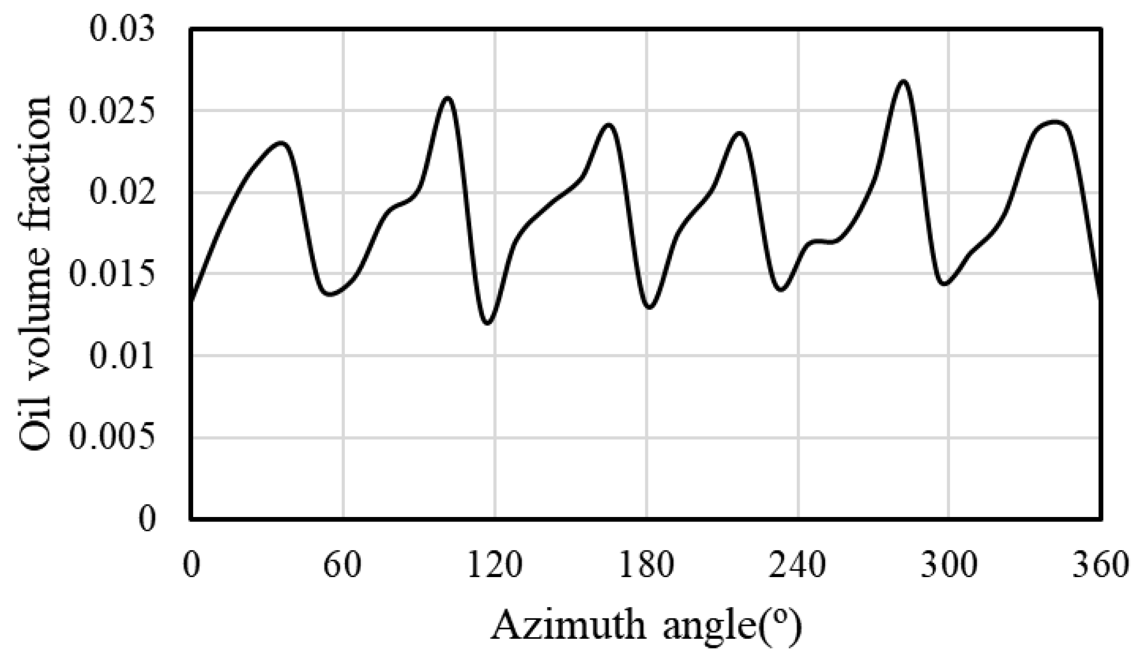
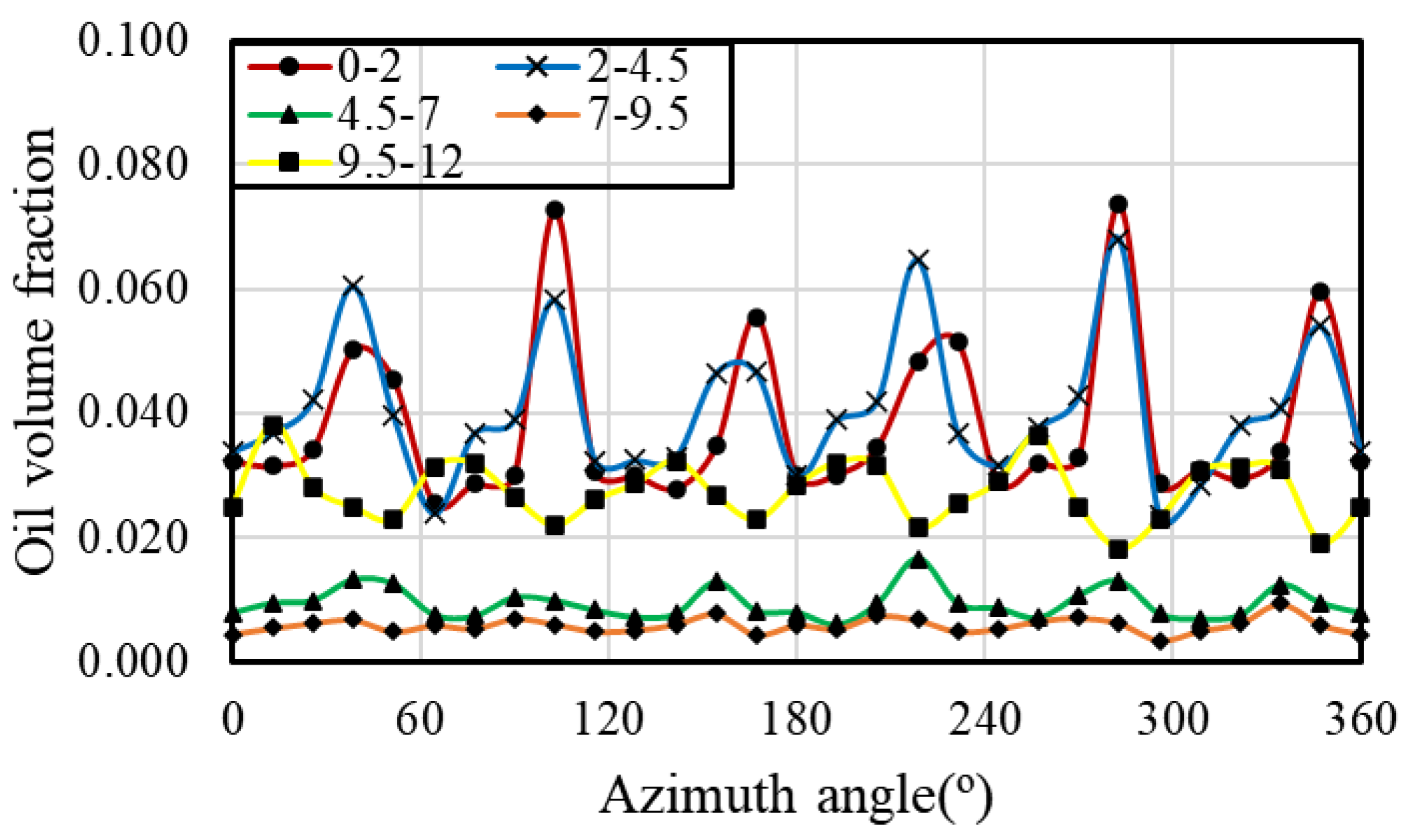
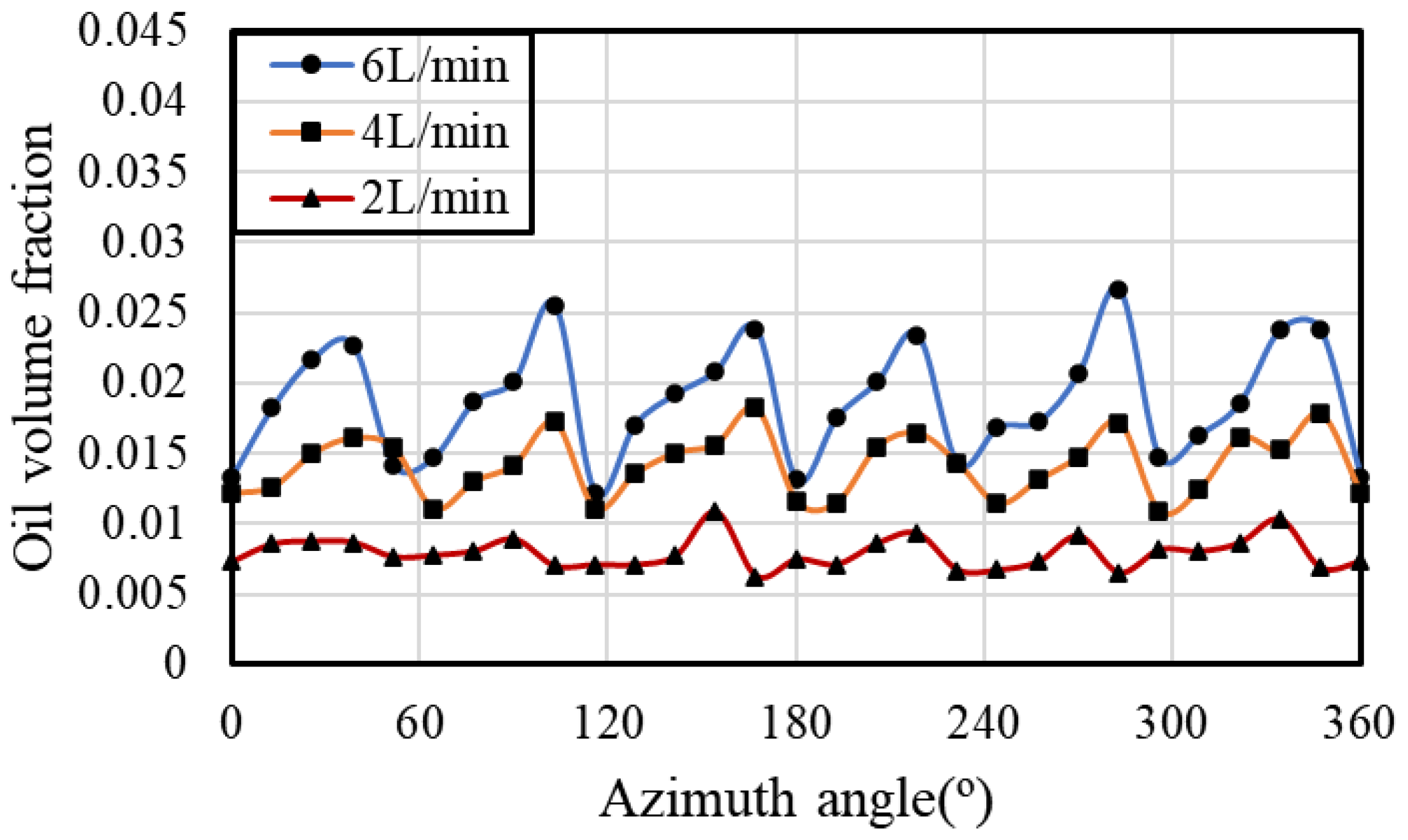
Oil volume fraction distribution inside the bearing is not uniform but periodic, and the cycle number along the circumference of the bearing cavity is equal to the under-race nozzle number. The peak of each cycle is reached near the nozzle, and its value is related to operating conditions and oil properties.
(2)
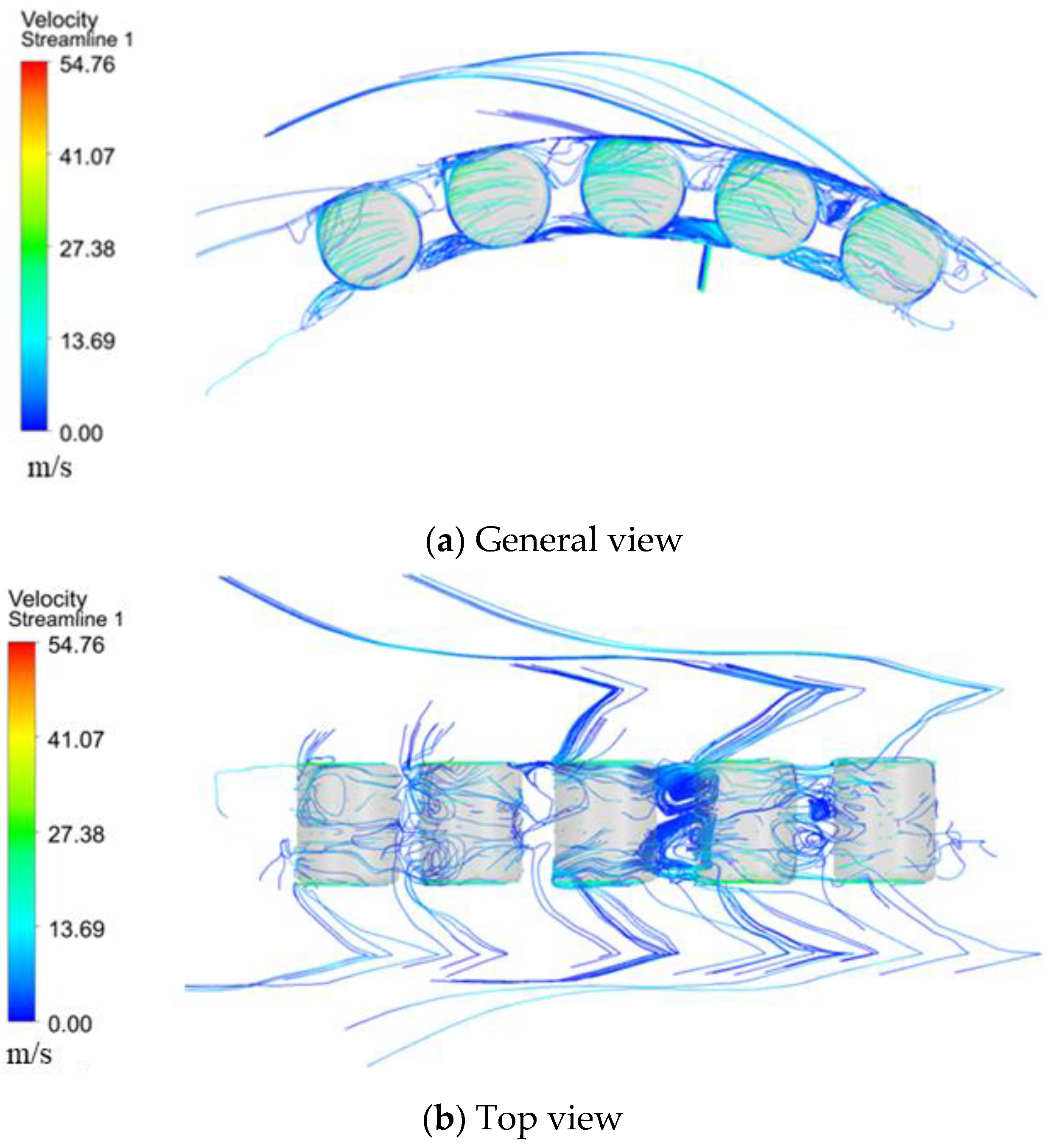
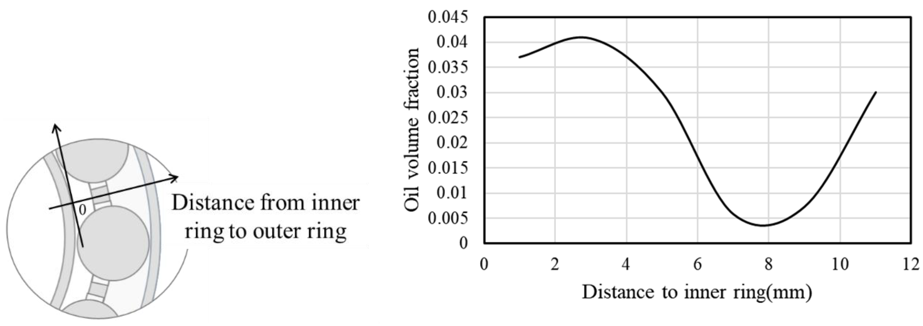
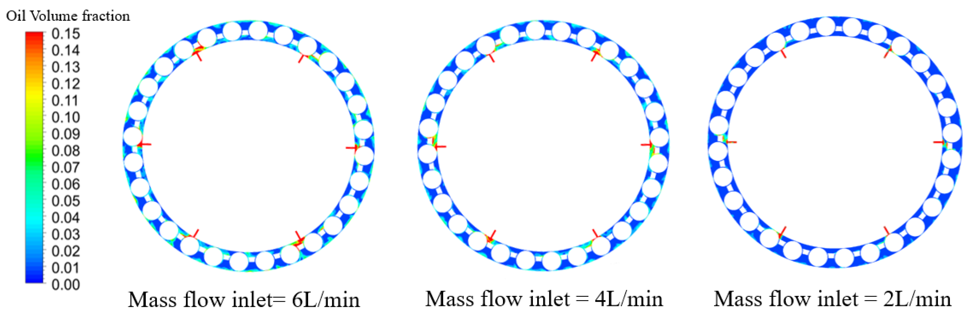
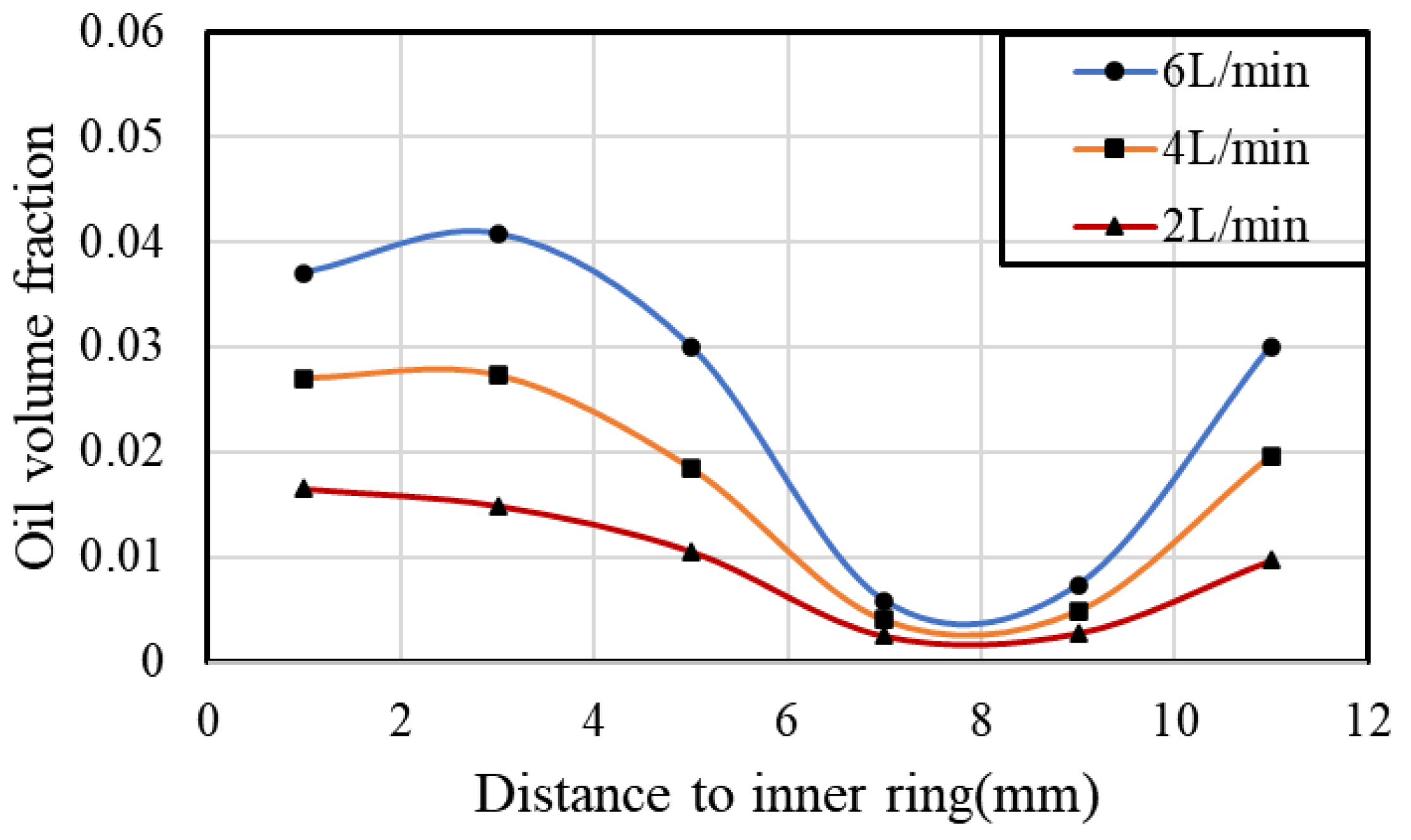
The oil phase tends to stay in the gap between the cage and the inner raceway for the bearing with the inner-race guidance cage, and only a small portion reaches the outer race. This phenomenon may result in poor lubricating or cooling conditions for the outer race, and some enhanced cooling measures should be employed.
(3)
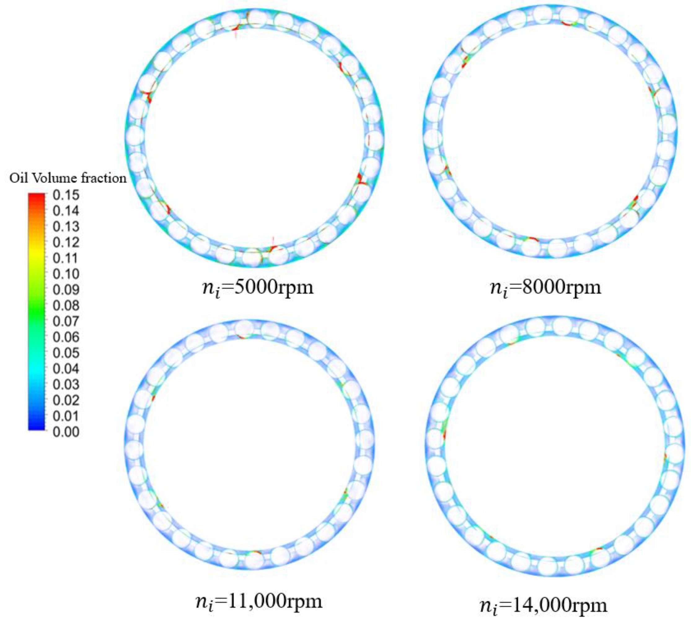
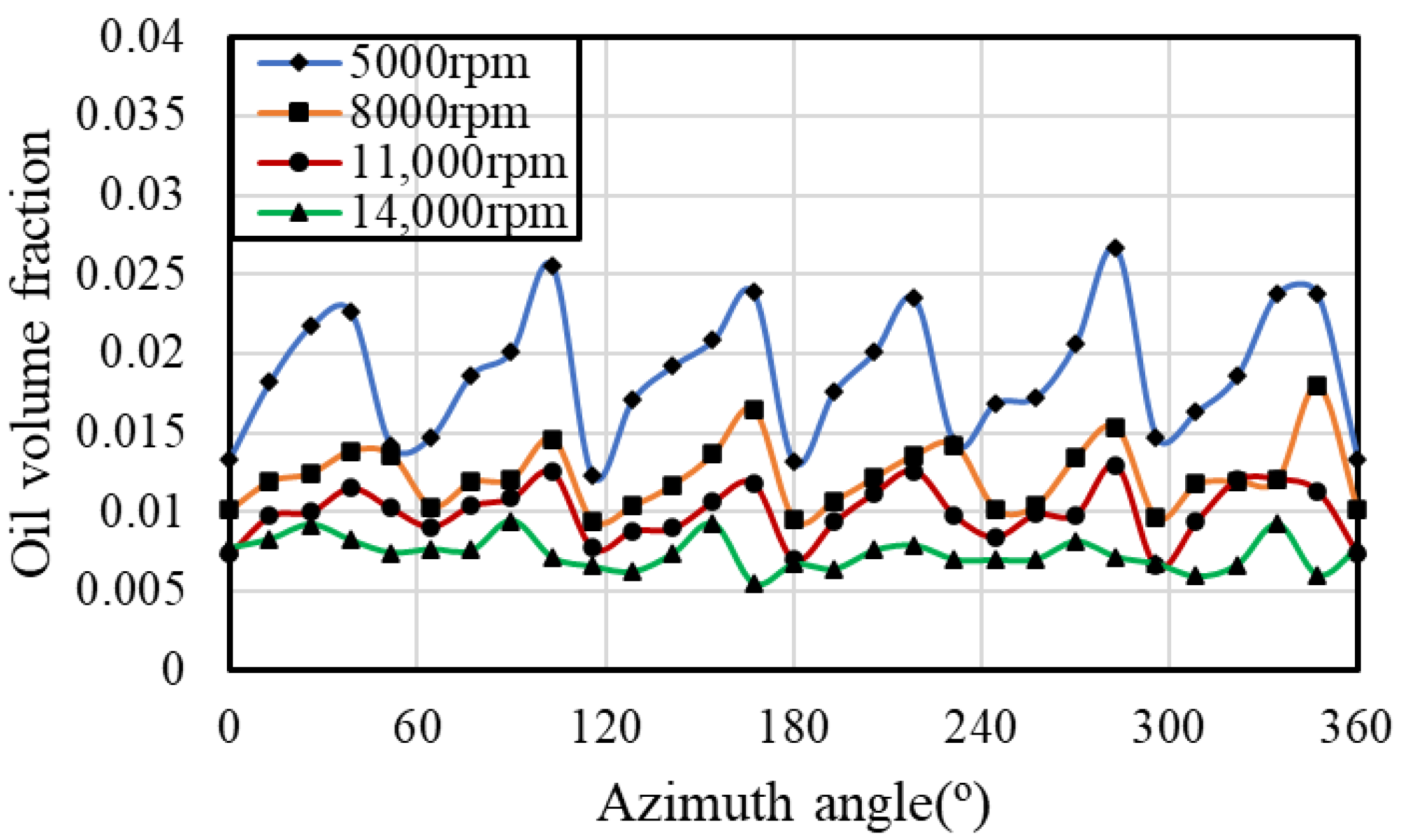
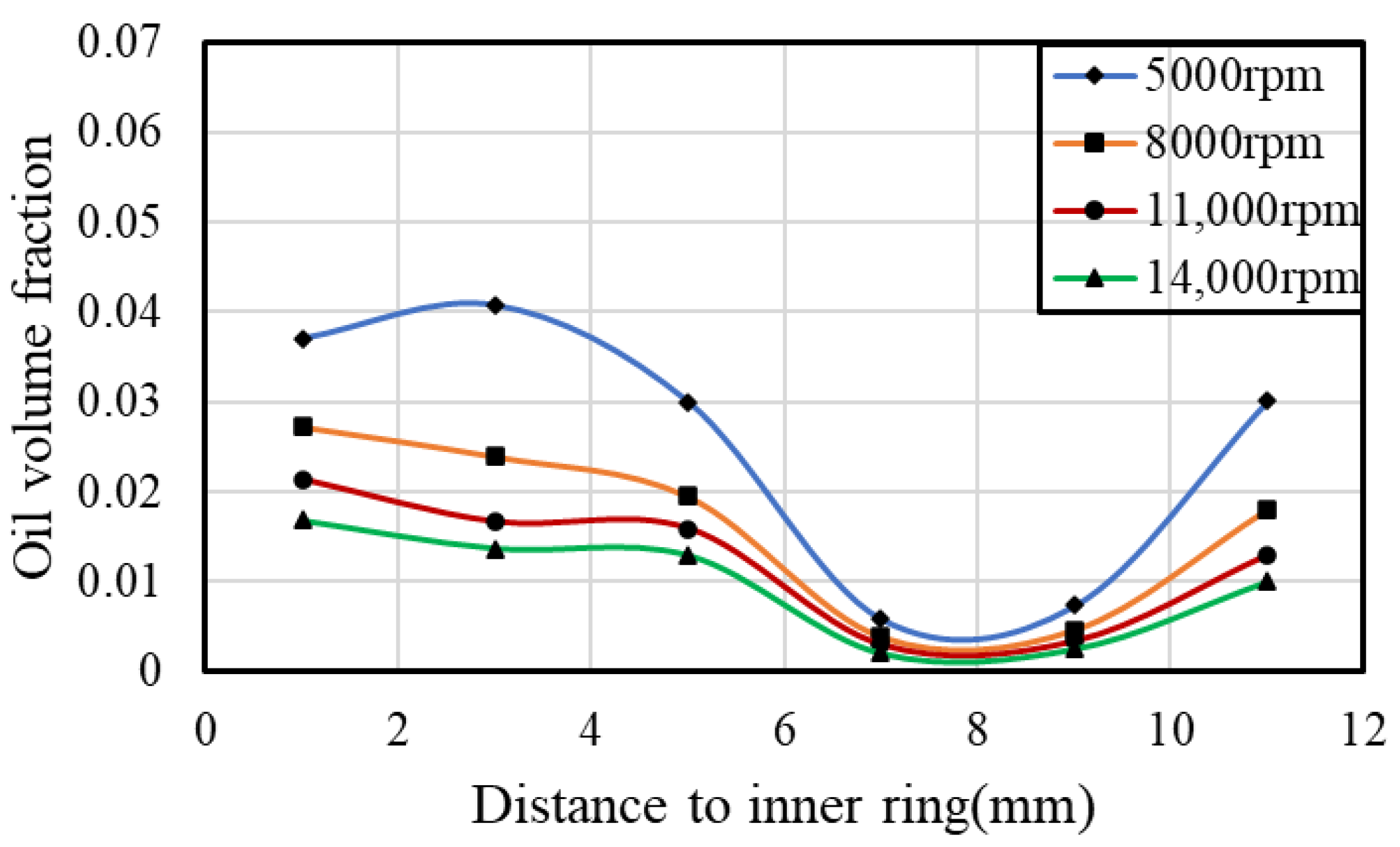
Higher rotating speed would decrease the oil volume fraction in the bearing because the oil is easier to exit the bearing. With stronger interaction between the oil and bearing components and higher relative rotating speed between the nozzles and rollers, oil distribution along the circumference direction is more uniform. On the contrary, adding oil flow rate would aggravate distribution differences both along the circumference direction and radial direction.
(4)
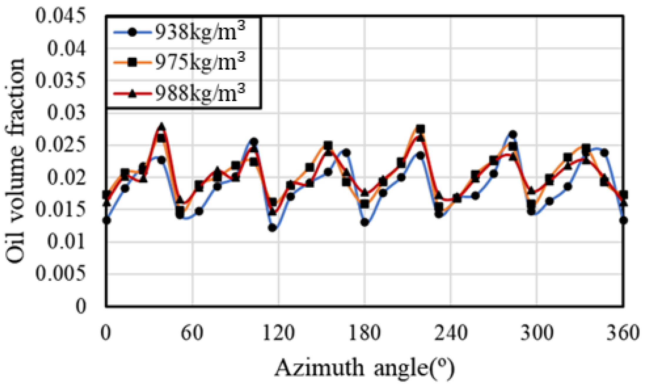
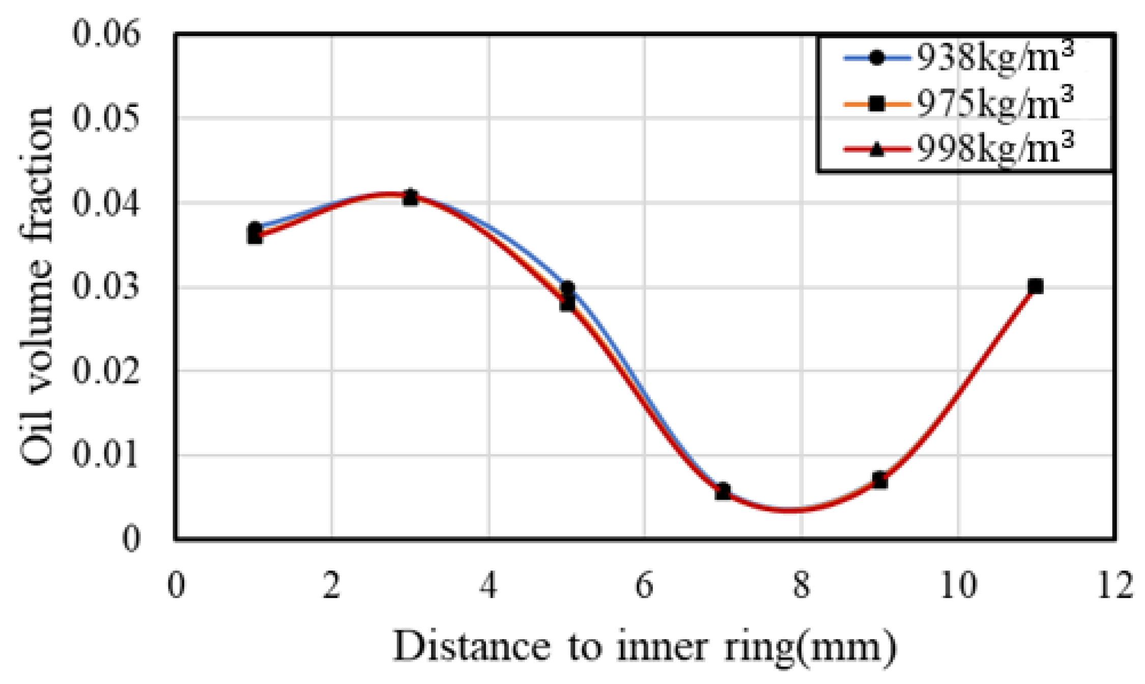
Higher oil viscosity leads to more uniform oil distribution along the circumference but reduces oil reaching the outer race. It increases oil flow resistance and makes it hard to flow through the gap between the cage pocket and the roller. In comparison, the effect of oil density is not obvious within a certain range of temperatures.

Author Contributions

Conceptualization, W.G. and Z.L.; methodology, W.G. and Y.L. (Yaguo Lyu); validation, C.L. and Y.L. (Yuanhao Li); formal analysis, C.L.; investigation, W.G. and C.L.; resources, Y.L. (Yuanhao Li); data curation, C.L. and Y.L. (Yuanhao Li); writing—original draft preparation, W.G.; writing—review and editing, W.G. and C.L.; visualization, C.L.; supervision, Y.L. (Yaguo Lyu); project administration, Z.L.; funding acquisition, W.G. All authors have read and agreed to the published version of the manuscript.

Funding

This research was funded by the National Science and Technology Major Project of China (Grant number: J2019-III-0023-0067), Science Center for Gas Turbine Project (Grant number: P2022-B-III-003-001), and the Natural Science Foundation of China (Grant number: 52005409).

Data Availability Statement

Data is contained within the article.

Conflicts of Interest

The authors declare no conflicts of interest. The funders had no role in the design of the study; in the collection, analyses, or interpretation of data; in the writing of the manuscript; or in the decision to publish the results.

References

  1. Adeniyi, A.A.; Morvan, H.; Simmons, K. A computational fluid dynamics simulation of oil–air flow between the cage and inner race of an aero-engine bearing. J. Eng. Gas Turbines Power 2017, 139, 012506. [Google Scholar] [CrossRef]
  2. Bao, H.; Hou, X.; Lu, F. Analysis of oil-air two-phase flow characteristics inside a ball bearing with under-race lubrication. Processes 2020, 8, 1223. [Google Scholar] [CrossRef]
  3. Gloeckner, P.; Rodwoy, C. The evolution of reliability and efficiency of aerospace bearing systems. Engineering 2017, 9, 962–991. [Google Scholar] [CrossRef]
  4. Adeniyi, A.A.; Morvan, H.; Simmons, K. A multiphase computational study of oil-air flow within the bearing sector of aeroengines. In Proceedings of the ASME Turbo Expo 2015: Turbine Technical Conference and Exposition, Montreal, QC, Canada, 15–19 June 2015. [Google Scholar]
  5. Simmons, K.; Harrison, L.; Korsukova, E.; Cageao, P. CFD study exploring jet configurations and jet pulsing for an aeroengine scoop-based oil delivery system. In Proceedings of the ASME Turbo Expo 2018: Turbomachinery Technical Conference and Exposition, Oslo, Norway, 11–15 June 2018. [Google Scholar]
  6. Wu, W.; Hu, C.; Hu, J.; Yuan, S.; Zhang, R. Jet cooling characteristics for ball bearings using the VOF multiphase model. Int. J. Therm. Sci. 2017, 116, 150–158. [Google Scholar] [CrossRef]
  7. Flouros, M.; Salpingidou, C.; Yakinthos, K.; Hirschmann, M.; Cottier, F. Ejector application for scavenging of an aero engine bearing chamber. J. Eng. Gas Turbines Power 2017, 139, 101202. [Google Scholar] [CrossRef]
  8. Willenborg, K.; Busam, S.; Wittig, S. Experimental studies of the boundary conditions leading to oil fire in the bearing chamber and in the secondary air system of aeroengines. In Proceedings of the ASME Turbo Expo: Power for Land, Sea, & Air, Amsterdam, The Netherlands, 3–6 June 2002. [Google Scholar]
  9. Coe, H.H.; Huller, F.T. Comparison of Predicted and Experimental Performance of Large-Bore Roller Bearing Operating to 3.0 Million DN; NASA: Washington, DC, USA, 1980.
  10. Parker, R.J. Comparison of Predicted and Experimental Thermal Performance of Angular-Contact Ball Bearings; NASA: Washington, DC, USA, 1984.
  11. Cavallaro, G.; Nelias, D.; Bon, F. Analysis of High-Speed Intershaft Cylindrical Roller Bearing with Flexible Rings. Tribol. Trans. 2005, 48, 154–164. [Google Scholar] [CrossRef]
  12. Arienti, M.; Sussman, M. An embedded level set method for sharp-interface multiphase simulations of Diesel injectors. Int. J. Multiph. Flow 2014, 59, 1–14. [Google Scholar] [CrossRef]
  13. Yan, K.; Wang, Y.; Zhu, Y.; Hong, J. Investigation on the effect of sealing condition on the internal flow pattern of high-speed ball bearing. Tribol. Int. 2017, 150, 85–93. [Google Scholar] [CrossRef]
  14. Hu, J.; Wu, W.; Wu, M.; Yuan, S. Numerical investigation of the air–oil two-phase flow inside an oil-jet lubricated ball bearing. Int. J. Heat Mass Transf. 2014, 68, 85–93. [Google Scholar] [CrossRef]
  15. Yan, K.; Wang, Y.; Zhu, Y.; Hong, J.; Zhai, Q. Investigation on heat dissipation characteristic of ball bearing cage and inside cavity at ultra-high rotation speed. Tribol. Int. 2016, 93, 470–481. [Google Scholar] [CrossRef]
  16. Zhang, R.; Wei, C.; Wu, W.; Yuan, S. CFD investigation on the influence of jet velocity of oil-jet lubricated ball bearing on the characteristics of lubrication flow field. In Proceedings of the 2015 International Conference on Fluid Power and Mechatronics (FPM), Harbin, China, 5–7 August 2015; pp. 1324–1328. [Google Scholar]
  17. Wu, W.; Hu, C.; Hu, J. Jet cooling for rolling bearings: Flow visualization and temperature distribution. Appl. Therm. Eng. Des. Process. Equip. Econ. 2016, 105, 217–224. [Google Scholar] [CrossRef]
  18. Wu, W.; Hu, J.; Yuan, S.; Hu, C. Numerical and experimental investigation of the stratified air-oil flow inside ball bearings. Int. J. Heat Mass Transf. 2016, 103, 619–626. [Google Scholar] [CrossRef]
  19. Liu, H.; Li, Y.; Liu, G. Numerical investigation of oil spray lubrication for transonic bearings. J. Braz. Soc. Mech. Sci. Eng. 2018, 40, 401. [Google Scholar] [CrossRef]
  20. Flouros, M. Reduction of Power Losses in Bearing Chambers Using Porous Screens Surrounding a Ball Bearing. J. Eng. Gas Turbines Power 2005, 128, 178–182. [Google Scholar] [CrossRef]
  21. Adeniyi, A.A.; Morvan, H.; Simmons, K. Oil-Air Flow Between the Cage and Inner Race of an Aeroengine Bearing. In Proceedings of the ASME Turbo Expo 2016: Turbomachinery Technical Conference and Exposition, Seoul, Republic of Korea, 13–17 June 2016. [Google Scholar]
  22. Gao, W.; Nelias, D.; Li, K.; Lyu, Y. A multiphase computational study of oil distribution inside roller bearings with under-race lubrication. Tribol. Int. 2019, 40, 105862. [Google Scholar] [CrossRef]
  23. Bao, H.; Hou, X.; Tang, X.; Lu, F. Analysis of temperature field and convection heat transfer of oil-air two-phase flow for ball bearing with under-race lubrication. Ind. Lubr. Tribol. 2021, 73, 817–821. [Google Scholar] [CrossRef]
  24. Jiang, L.; Lyu, Y.; Gao, W.; Zhu, P.; Liu, Z. Numerical investigation of the oil–air distribution inside ball bearings with under-race lubrication. Proc. Inst. Mech. Eng. Part J J. Eng. Tribol. 2022, 236, 499–513. [Google Scholar] [CrossRef]
  25. Gong, P.; Liu, Z.; Yu, Q.; Chen, F. Research on internal two-phase flow in the local micro-clearance design of a high-speed ball bearing with under-race lubrication. Lubr. Sci. 2024, 36, 216–230. [Google Scholar] [CrossRef]
  26. Bristot, A.; Morvan, H.P.; Simmons, K.A. Evaluation of a volume of fluid CFD methodology for the oil film thickness estimation in an aero-engine bearing chamber. In Proceedings of the ASME Turbo Expo 2016: Turbomachinery Technical Conference and Exposition, Seoul, Republic of Korea, 13–17 June 2016. [Google Scholar]
  27. Yokoi, K. A practical numerical framework for free surface flows based on CLSVOF method, multi-moment methods and density-scaled CSF model: Numerical simulations of droplet splashing. J. Comput. Phys. 2013, 232, 252–271. [Google Scholar] [CrossRef]
  28. Ashgriz, N.; Mostaghimi, J. An introduction to computational fluid dynamics. In Fluid Flow Handbook 1; University of Toronto: Toronto, ON, Canada, 2002; pp. 1–49. [Google Scholar]
  29. Campos, A.; Sottomayor, A.; Seabra, J. Non-newtonian thermal analysis of an EHD contact lubricated with MIL-L-23699 oil. Tribol. Int. 2006, 39, 1732–1744. [Google Scholar] [CrossRef]
Figure 1. Configuration of the roller bearing with under-race lubrication.
Lubricants 12 00133 g001
Figure 2. Computational domain of the bearing with under-race lubrication.
Lubricants 12 00133 g002
Figure 3. Computational mesh structure and boundary condition.
Lubricants 12 00133 g003
Figure 4. Oil-phase accumulation process inside the bearing cavity at different times.
Lubricants 12 00133 g004
Figure 5. Oil–air two-phase flow pattern inside the bearing cavity.
Lubricants 12 00133 g005
Figure 6. Streamline of oil phase around rollers inside the bearing cavity.
Lubricants 12 00133 g006
Figure 7. Radial and axial sections for monitoring oil mass flow within the calculation domain.
Lubricants 12 00133 g007
Figure 8. Oil volume fraction distribution along the circumference direction.
Lubricants 12 00133 g008
Figure 9. Oil volume fraction distribution along the radial direction.
Lubricants 12 00133 g009
Figure 10. Oil volume fraction distribution along the circumference in different radial positions.
Lubricants 12 00133 g010
Figure 11. Oil–air two-phase distribution with different rotating speeds.
Lubricants 12 00133 g011
Figure 12. Oil volume fraction distribution along the circumference with different rotating speeds.
Lubricants 12 00133 g012
Figure 13. Oil volume fraction distribution along the radial direction with different rotating speeds.
Lubricants 12 00133 g013
Figure 14. Oil–air two-phase distribution with different flow rates.
Lubricants 12 00133 g014
Figure 15. Oil volume fraction distribution along the circumference with different flow rates.
Lubricants 12 00133 g015
Figure 16. Oil volume fraction distribution along the radial direction with different flow rates.
Lubricants 12 00133 g016
Figure 17. Oil–air two-phase distribution with different oil viscosities.
Lubricants 12 00133 g017
Figure 18. Oil volume fraction distribution along the circumference with different oil viscosities.
Lubricants 12 00133 g018
Figure 19. Oil volume fraction distribution along the radial direction with different oil viscosities.
Lubricants 12 00133 g019
Figure 20. Oil–air two-phase distribution with different oil densities.
Lubricants 12 00133 g020
Figure 21. Oil volume fraction distribution along the circumference with different oil densities.
Lubricants 12 00133 g021
Figure 22. Oil volume fraction distribution along the radial direction with different oil densities.
Lubricants 12 00133 g022
Table 1. Roller bearing specifications.
Pitch diameter (mm)142
Outer race width (mm)36
Inner race width (mm)30
Number of rollers28
Roller diameter (mm)12
Roller length (mm)14
Oil nozzle diameter (mm)1
Cage guidanceInner ring
Table 2. Mesh independence verification.
Mesh Element NumbersAverage Oil Volume Fraction
2.50 millionUnstable
3.78 million0.0156
6.21 million0.0159
Disclaimer/Publisher’s Note: The statements, opinions and data contained in all publications are solely those of the individual author(s) and contributor(s) and not of MDPI and/or the editor(s). MDPI and/or the editor(s) disclaim responsibility for any injury to people or property resulting from any ideas, methods, instructions or products referred to in the content.

