An Experimental Study on the Distribution of Grease in Cylindrical Roller Bearings


Abstract
:1. Introduction
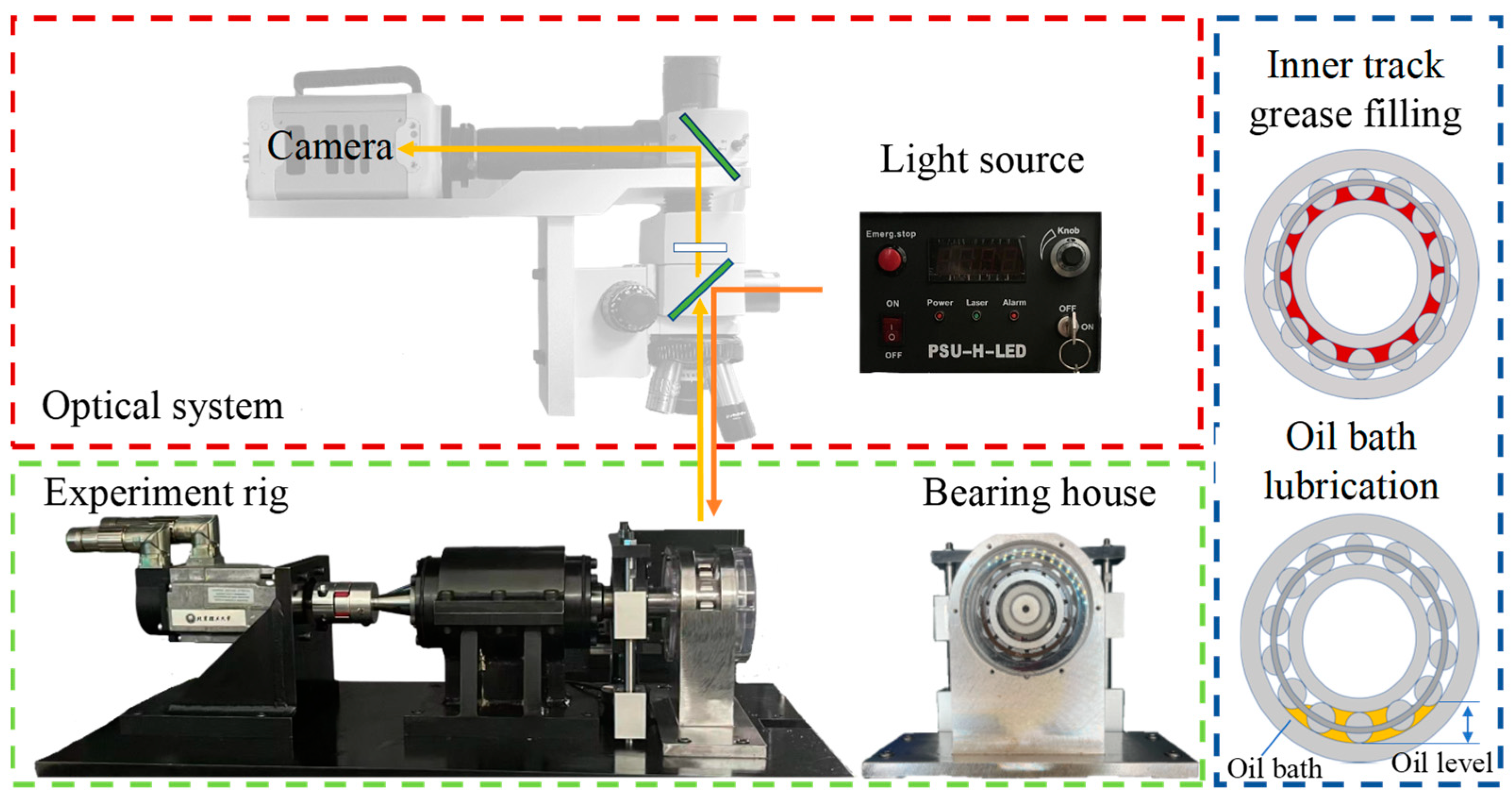
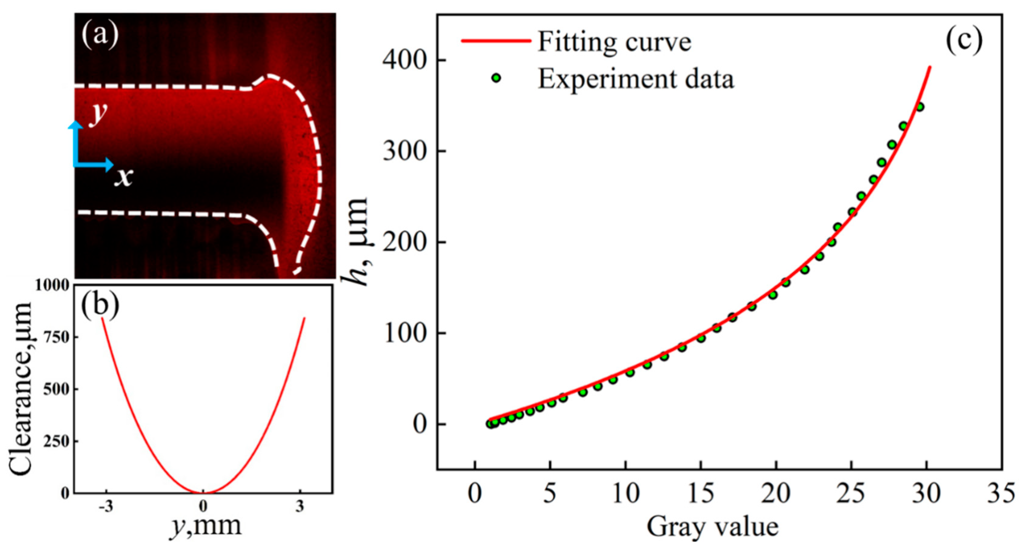
2. Experimental
3. Experimental Results
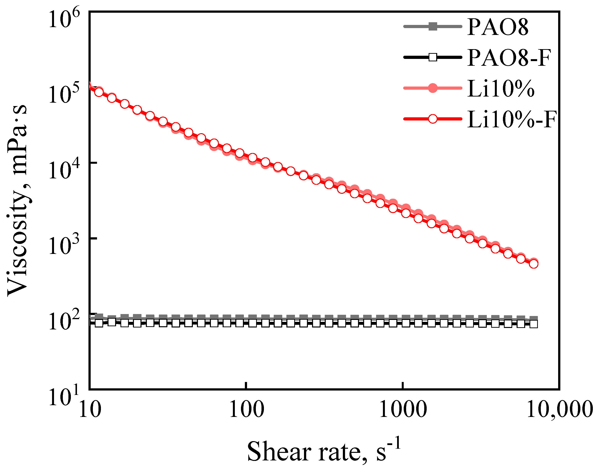
3.1. The Preparation of the Lubricating Medium
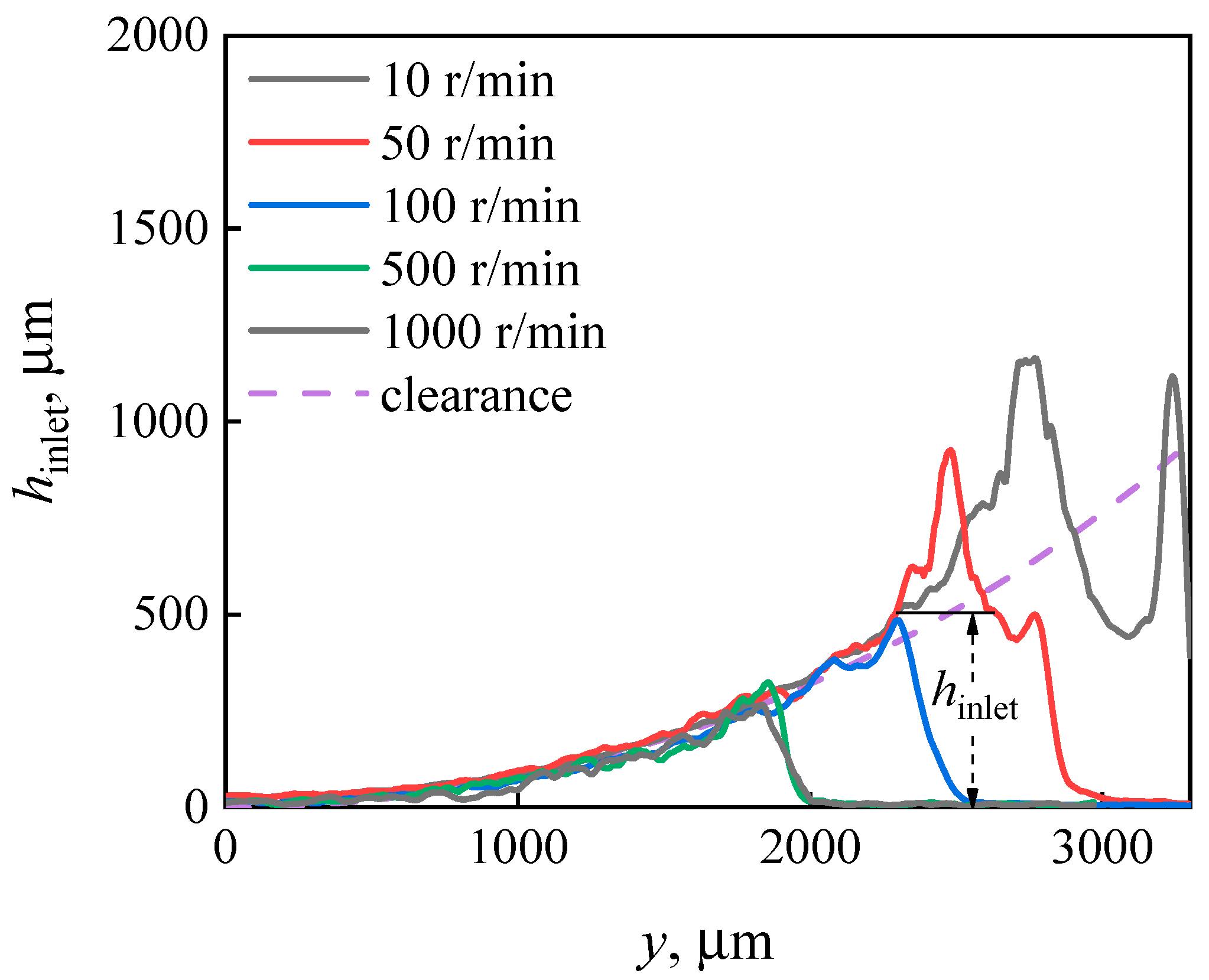
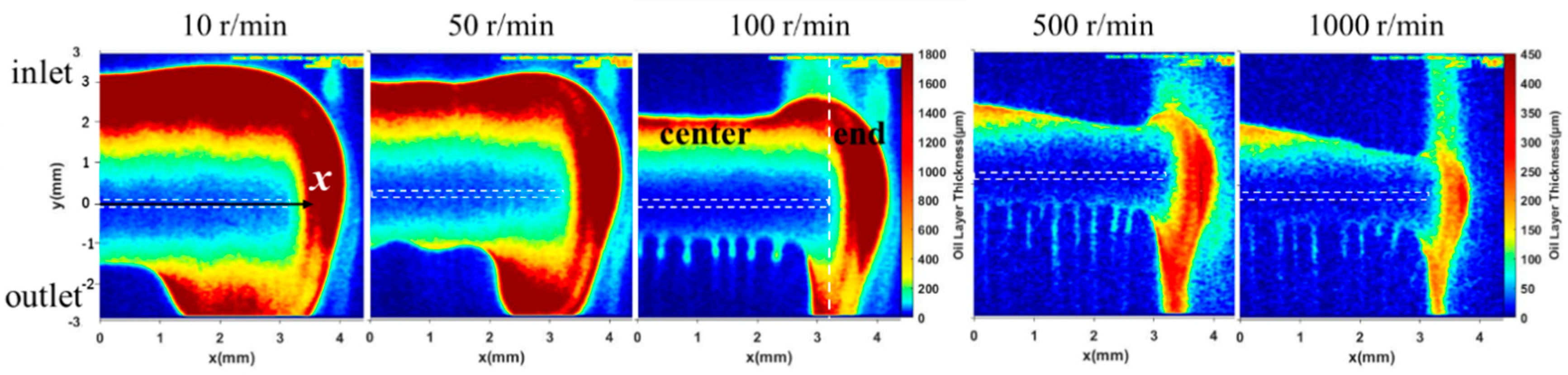
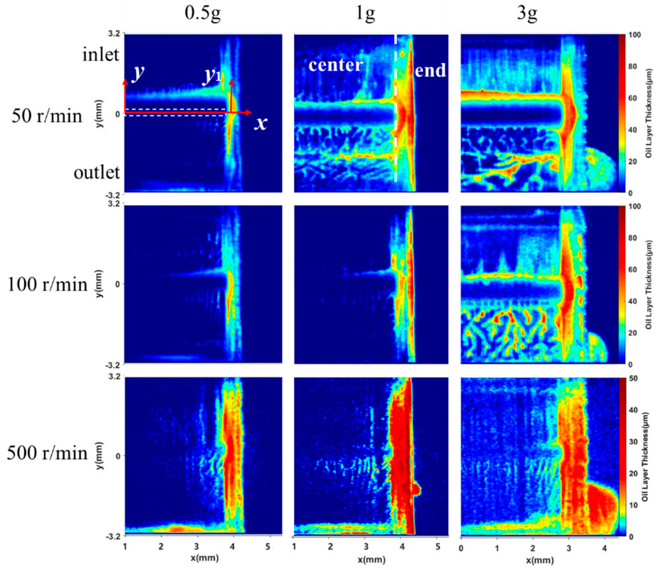
3.2. The Distribution of the Lubricating Oil
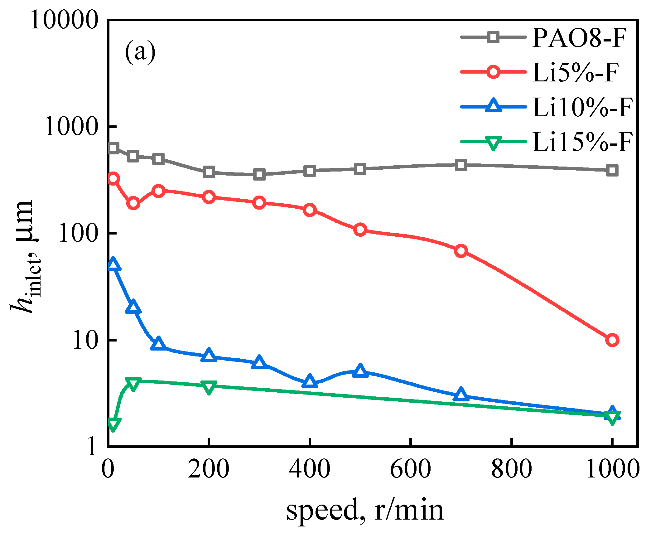
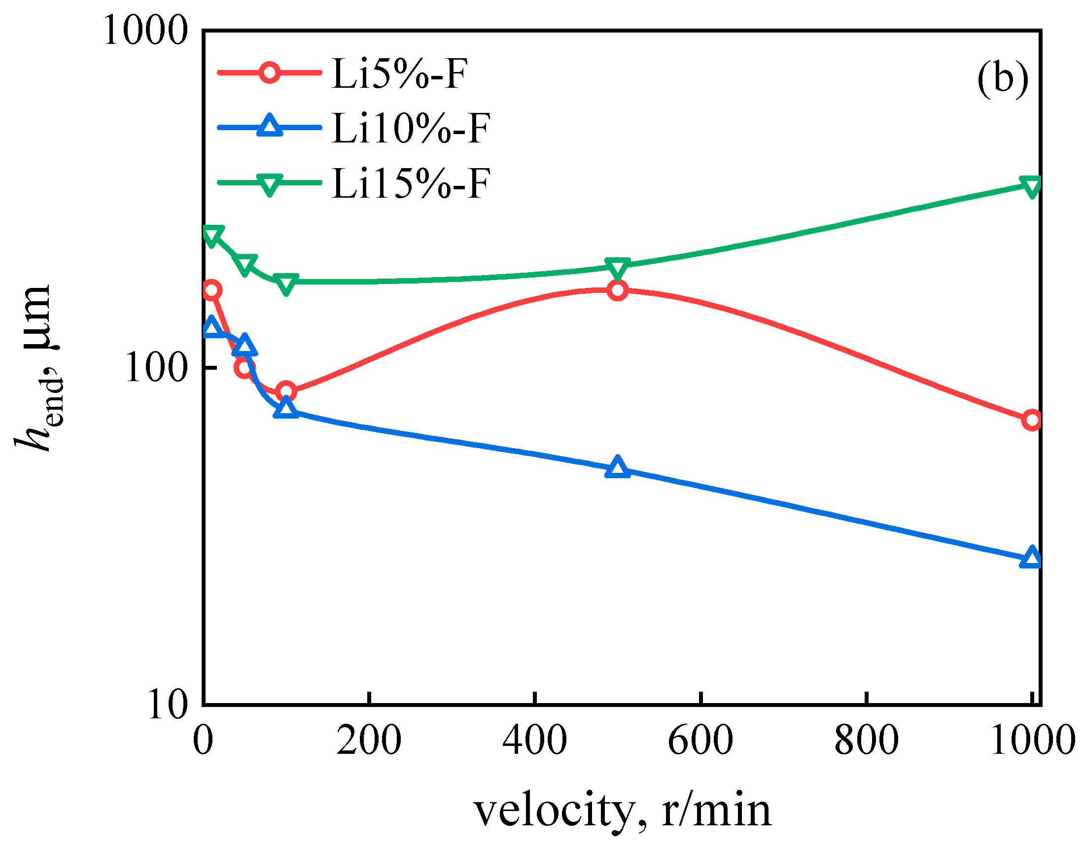
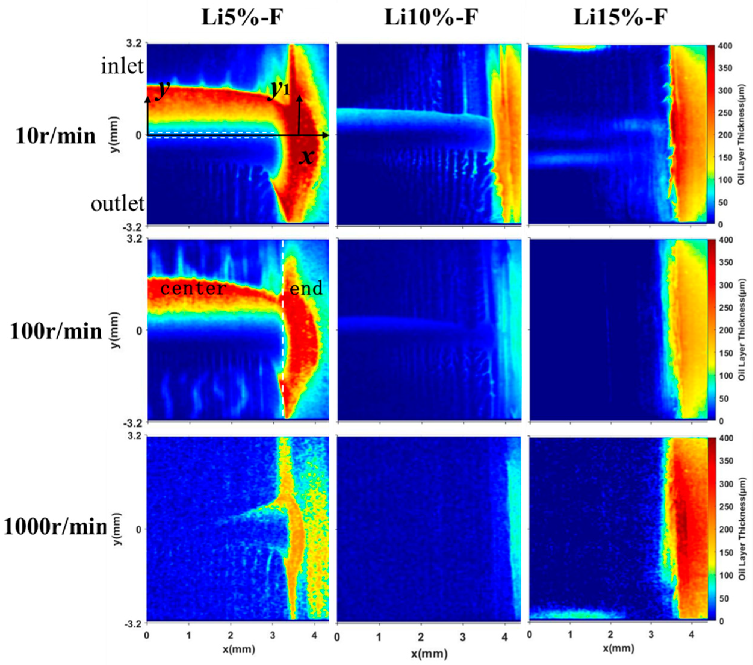
3.3. The Distribution of the Grease
4. Discussion
5. Conclusions
- The reservoir around the line contact area in a cylindrical roller bearing mainly has a rectangular shape. Rotating speed is the most important factor influencing the layer thickness of the reservoir. Higher speeds lead to smaller reservoirs.
- There are two lubricant supply modes for the line contact area in a cylindrical roller bearing: circumferential and axial. In general, circumferential supply is the main form; when the supply is very small or when there are higher speeds, it can be observed that the axial supply cannot be ignored.
- For axial supply, a small grease reservoir can be formed at the end area, and grease fingers are formed in the outlet area developing inward. In addition, different contact areas can be supplemented by the tail flow exchange while migrating to the center.
Author Contributions
Funding
Data Availability Statement
Acknowledgments
Conflicts of Interest
References
- Wilson, R.A. The relative thickness of grease and oil films in rolling bearings. Proc. Inst. Mech. Eng. 1979, 193, 185–192. [Google Scholar] [CrossRef]
- Åström, H.; Isaksson, O.; Höglund, E. Video recordings of an EHD point contact lubricated with grease. Tribol. Int. 1991, 24, 179–184. [Google Scholar] [CrossRef]
- Morales-Espejel, G.E.; Lugt, P.M.; Pasaribu, H.; Cen, H. Film thickness in grease lubricated slow rotating rolling bearings. Tribol. Int. 2014, 74, 7–19. [Google Scholar] [CrossRef]
- Kimura, Y.; Endo, T.; Dong, D. EHL with grease at low speeds. In Advanced Tribology: Proceedings of CIST2008 & ITS-IFToMM2008; Springer: Berlin/Heidelberg, Germany, 2010; pp. 15–19. [Google Scholar]
- Dong, D.; Komoriya, T.; Endo, T.; Kimura, Y. Formation of EHL film with grease in ball bearings at low speeds. J. Jpn. Soc. Tribol. 2012, 57, 568–574. [Google Scholar]
- Cann, P. Starved grease lubrication of rolling contacts. Tribol. Trans. 1999, 42, 867–873. [Google Scholar] [CrossRef]
- Poon, S.-Y. An experimental study of grease in elastohydrodynamic lubrication. J. Tribol. 1972, 94, 27–34. [Google Scholar] [CrossRef]
- Coy, J.J.; Zaretsky, E.V. Some limitations in applying classical EHD film thickness formulas to a high-speed bearing. J. Tribol. 1981, 103, 295–301. [Google Scholar] [CrossRef]
- Chennaoui, M.; Fowell, M.; Liang, H.; Kadiric, A. A Novel Set-up for In-situ Measurement and Mapping of Lubricant Film Thickness in a Model Rolling Bearing Using Interferometry and Ratiometric Fluorescence Imaging. Tribol. Lett. 2022, 70, 85. [Google Scholar] [CrossRef]
- Gonçalves, D.E.; Campos, A.V.; Seabra, J.H. An experimental study on starved grease lubricated contacts. Lubricants 2018, 6, 82. [Google Scholar] [CrossRef]
- Liang, H.; Zhang, Y.; Wang, W. Influence of the cage on the migration and distribution of lubricating oil inside a ball bearing. Friction 2022, 10, 1035–1045. [Google Scholar] [CrossRef]
- Aamer, S.; Sadeghi, F.; Russell, T.; Peterson, W.; Meinel, A.; Grillenberger, H. Lubrication, flow visualization, and multiphase CFD modeling of ball bearing cage. Tribol. Trans. 2022, 65, 1088–1098. [Google Scholar] [CrossRef]
- Aamer, S.; Sadeghi, F.; Meinel, A. Cylindrical roller bearing cage pocket lubrication. Tribol. Int. 2023, 188, 108851. [Google Scholar] [CrossRef]
- Sakai, K.; Tokumo, Y.; Ayame, Y.; Shitara, Y.; Tanaka, H.; Sugimura, J. Effect of Formulation of Li Greases on Their Flow and Ball Bearing Torque. Tribol. Online 2016, 11, 168–173. [Google Scholar] [CrossRef]
- Tichy, J.; Menut, M.; Oumahi, C.; Muller, S.; Bou-Saïd, B. Grease flow based on a two-component mixture model. Tribol. Int. 2021, 153, 106638. [Google Scholar] [CrossRef]
- Fischer, D.; von Goeldel, S.; Jacobs, G.; Stratmann, A. Numerical investigation of effects on replenishment in rolling point contacts using CFD simulations. Tribol. Int. 2021, 157, 106858. [Google Scholar] [CrossRef]
- Chen, H.; Liang, H.; Wang, W.; Zhang, S. Investigation on the oil transfer behaviors and the air-oil interfacial flow patterns in a ball bearing under different capillary conditions. Friction 2023, 11, 228–245. [Google Scholar] [CrossRef]
- Pemberton, J.; Cameron, A. An Optical Study of the Lubrication of a 65 mm Cylindrical Roller Bearing. Ind. Lubr. Tribol. 1979, 33, 84–94. [Google Scholar] [CrossRef]
- Chen, J.; Tanaka, H.; Sugimura, J. Experimental Study of Starvation and Flow Behavior in Grease-Lubricated EHD Contact. Tribol. Online 2015, 10, 48–55. [Google Scholar] [CrossRef]
- Huang, L.; Guo, D.; Wen, S. Film thickness decay and replenishment in point contact lubricated with different greases: A study into oil bleeding and the evolution of lubricant reservoir. Tribol. Int. 2016, 93, 620–627. [Google Scholar] [CrossRef]
- Huang, L.; Guo, D.; Wen, S.; Wan, G.T.Y. Effects of Slide/Roll Ratio on the Behaviours of Grease Reservoir and Film Thickness of Point Contact. Tribol. Lett. 2014, 54, 263–271. [Google Scholar] [CrossRef]
- Jian, N.; Li, X.; Yang, P.; Guo, F. Observation of lubrication state and lubricant replenishment under sliding-rolling motions with single-charging amount. Tribology 2021, 41, 9–16. [Google Scholar]
- Han, B.; Wang, W.; Zhao, Z. Oil Replenishment Mechanism of Lubricated Contact at Low Speed. Tribology 2016, 36, 341–347. [Google Scholar]
- Cen, H.; Lugt, M.P. Film thickness in a grease lubricated ball bearing. Tribol. Int. 2019, 134, 26–35. [Google Scholar] [CrossRef]
- Cen, H.; Lugt, P.M. Replenishment of the EHL contacts in a grease lubricated ball bearing. Tribol. Int. 2020, 146, 106064. [Google Scholar] [CrossRef]
- Dwyer-Joyce, R.; Reddyhoff, T.; Drinkwater, B. Operating limits for acoustic measurement of rolling bearing oil film thickness. Tribol. Trans. 2004, 47, 366–375. [Google Scholar] [CrossRef]
- Dou, P.; Jia, Y.; Wu, T.; Peng, Z.; Yu, M.; Reddyhoff, T. High-accuracy incident signal reconstruction for in-situ ultrasonic measurement of oil film thickness. Mech. Syst. Signal Process. 2021, 156, 107669. [Google Scholar] [CrossRef]
- Li, M.; Liu, H.; Xu, C.; Jing, M.; Dong, G. Ultrasonic measurement of cylindrical roller–bearing lubricant film distribution with two juxtaposed transducers. Tribol. Trans. 2017, 60, 79–86. [Google Scholar] [CrossRef]
- Noda, T.; Shibasaki, K.; Miyata, S.; Taniguchi, M. X-ray CT imaging of grease behavior in ball bearing and numerical validation of multi-phase flows simulation. Tribol. Online 2020, 15, 36–44. [Google Scholar] [CrossRef]
- Lugt, P.M.; Velickov, S.; Tripp, J.H. On the chaotic behavior of grease lubrication in rolling bearings. Tribol. Trans. 2009, 52, 581–590. [Google Scholar] [CrossRef]
- Sato, N.; Sakaguchi, T. Improvement of grease leakage prevention for ball bearings due to geometrical change of ribbon cages. Tech. Rev. 2010, 78, 91–97. [Google Scholar]
- Fowell, M.; Myant, C.; Spikes, H.; Kadiric, A. A study of lubricant film thickness in compliant contacts of elastomeric seal materials using a laser induced fluorescence technique. Tribol. Int. 2014, 80, 76–89. [Google Scholar] [CrossRef]
- Franken, M.; Chennaoui, M.; Wang, J. Mapping of grease migration in high-speed bearings using a technique based on fluorescence spectroscopy. Tribol. Trans. 2017, 60, 789–793. [Google Scholar] [CrossRef]
- Chen, H.; Wang, W.; Ge, X.; Liang, H. Pixel-dependent laser-induced fluorescence method for determining thin liquid film thickness distribution. Phys. Fluids 2024, 36, 012111. [Google Scholar] [CrossRef]
- Hidrovo, C.H.; Hart, D.P. Emission reabsorption laser induced fluorescence (ERLIF) film thickness measurement. Meas. Sci. Technol. 2001, 12, 467. [Google Scholar] [CrossRef]


| Roller of the Bearing | Glass Ring | |
|---|---|---|
| Elastic Young’s modulus (GPa) | 210 | 75 |
| Poisson ratio | 0.293 | 0.215 |
| Radius (mm) | 5.5 | 35.75 |
| Grease supply (g) | 1~3 | |
| Temperature t0 (°C) | 24 ± 1 | |
Disclaimer/Publisher’s Note: The statements, opinions and data contained in all publications are solely those of the individual author(s) and contributor(s) and not of MDPI and/or the editor(s). MDPI and/or the editor(s) disclaim responsibility for any injury to people or property resulting from any ideas, methods, instructions or products referred to in the content. |
© 2024 by the authors. Licensee MDPI, Basel, Switzerland. This article is an open access article distributed under the terms and conditions of the Creative Commons Attribution (CC BY) license (https://creativecommons.org/licenses/by/4.0/).
Share and Cite
Liang, H.; Lu, Y.; Wang, W.; Sun, Y.; Zhao, J.; Guo, Y. An Experimental Study on the Distribution of Grease in Cylindrical Roller Bearings. Lubricants 2024, 12, 145. https://doi.org/10.3390/lubricants12050145
Liang H, Lu Y, Wang W, Sun Y, Zhao J, Guo Y. An Experimental Study on the Distribution of Grease in Cylindrical Roller Bearings. Lubricants. 2024; 12(5):145. https://doi.org/10.3390/lubricants12050145
Chicago/Turabian StyleLiang, He, Yan Lu, Wenzhong Wang, Yi Sun, Jingjing Zhao, and Yulong Guo. 2024. "An Experimental Study on the Distribution of Grease in Cylindrical Roller Bearings" Lubricants 12, no. 5: 145. https://doi.org/10.3390/lubricants12050145