Article

Numerical Optimization Analysis of Floating Ring Seal Performance Based on Surface Texture

1
Aeronautical Engineering Institute, Civil Aviation University of China, Tianjin 300300, China
2
State Key Laboratory of Mechanical Transmission, Chongqing University, Chongqing 400044, China
3
Sino-European Institute of Aviation Engineering, Civil Aviation University of China, Tianjin 300300, China
4
AECC Hunan Aviation Powerplant Research Institute, Zhuzhou 412002, China
5
Science and Technology on Helicopter Tranmission Laboratory, Zhuzhou 412002, China
*
Author to whom correspondence should be addressed.
Lubricants 2024, 12(7), 241; https://doi.org/10.3390/lubricants12070241
Submission received: 27 May 2024 / Revised: 21 June 2024 / Accepted: 1 July 2024 / Published: 3 July 2024
(This article belongs to the Special Issue Mechanical Tribology and Surface Technology)

Abstract

:
Much research and practical experience have shown that the utilization of textures has an enhancing effect on the performance of dynamic seals and the dynamic pressure lubrication of gas bearings. In order to optimize the performance of floating ring seals, this study systematically analyzes the effects of different texture shapes and their parameters. The Reynolds equation of the gas is solved by the successive over-relaxation (SOR) iteration method. The pressure and thickness distributions of the seal gas film are solved to derive the floating force, end leakage, friction, and the ratio of buoyancy to leakage within the seal. The effects of various texture shapes, including square, 2:1 rectangle, triangle, hexagon, and circle, as well as their parameters, such as texture depth, angle, and area share, on the sealing performance are discussed. Results show that the texture can increase the air film buoyancy and reduce friction, but it also increases the leakage by a small amount. Square textures and rectangular textures are relatively effective. The deeper the depth of the texture within a certain range, the better the overall performance of the floating ring seal. As the texture area percentage increases, leakage tends to increase and friction tends to decrease. A fractal roughness model is developed, the effect of surface roughness on sealing performance is briefly discussed, and finally the effect of surface texture with roughness is analyzed. Some texture parameters that can significantly optimize the sealing performance are obtained. Rectangular textures with certain parameters enhance the buoyancy of the air film by 81.2%, which is the most significant enhancement effect. This rectangular texture reduces friction by 25.8% but increases leakage by 79.5%. The triangular textures increase buoyancy by 28.02% and leakage increases by only 10.08% when the rotation speed is 15,000 r/min. The results show that texture with appropriate roughness significantly optimizes the performance of the floating ring seal.

1. Introduction

A floating ring seal is a non-contact fluid seal installed on a rotor, which separates two chambers with a high-pressure drop by a high-pressure fluid film formed by high-speed rotation of the rotor and eccentric operation of the floating ring [1,2]. Its excellent reliability and high sealing efficiency are of great significance for the safe operation of rotating machinery. Floating ring seals are typically installed within steel or titanium supporting rings to minimize the sealing clearance and avoid rubbing with the rotor. However, the non-contact seals that are installed on the rotor are constrained by the balance between achieving optimal sealing clearance and minimizing the risk of rotor rubbing.
With the operating environment of rotating machinery becoming increasingly complex, the stability and service life of the sealing system are subject to higher demands. In response, researchers have undertaken extensive studies on the mechanisms of floating ring seals and the diverse factors that influence their sealing performance. Lee et al. [3] proposed a numerical method for calculating the static and dynamic characteristics of floating ring seals. By using the finite difference method, they solved the bulk-flow model under eccentric conditions and researched the influences of rotating speed and pressure drop on the performance of the floating ring seal. Bae et al. [4] used numerical analysis to evaluate the friction on the front end of the floating ring of a turbopump oxidation pump, and researched the effects of rotor vibration on the radial force acting on the floating ring and the flow characteristics around the floating ring seal. Furthermore, they researched the effects of rotational speeds and clearance dimensions on the leakage of the floating ring seal, and utilized the findings to optimize the performance. The experimental results are in good agreement with the numerical analysis. Shi et al. [5] established a calculation method for the working clearance of gas floating ring seals. By selecting appropriate insert ring materials, the sealing clearance of the floating ring can be kept stable. By using the “micro-variable clearance” design method to calculate the ideal floating ring material, better results can be achieved. Anbarsooz et al. [6] conducted computational fluid dynamics simulations on the floating ring seal of a carbon dioxide centrifugal compressor. They studied the effect of the annular clearance on the sealing performance and found that the leakage rate significantly increased with increase in the clearance. The leakage function remained almost unchanged with increase in the inlet total pressure and temperature. The results also showed that the minimum flow velocity required to block the leakage significantly increased with increase in the clearance. Their works provide guidance for improving the performance of the floating ring seal.
Surface texture technology is an emerging and effective means of achieving lubrication and friction reduction. By changing the micro-surface morphology of the shaft sleeve in fluid sealing systems, significant achievements have been realized in improving the fluid dynamic pressure effect of the lubricating surface and avoiding surface adhesion. It has now become a research hotspot in the field of advanced sealing technology [7,8,9]. Zhang et al. [10] have established an analysis model of oil film force for floating ring seals considering the influence of the axial pressure gradient. They studied the influence of groove geometry size on dynamic response and analyzed the stability of the floating ring. The analysis model is based on the Reynolds equation for oil lubrication and the assumption of short bearings [11], with consideration of the Lomakin effect of the fluid. Adjemout et al. [12] studied the influence of surface textures on the mechanical sealing performance using numerical analysis. They investigated the local and global effects of various texture shapes, directions, area ratios, and depth ratios on the fluid mechanics performance of mechanical seals, providing valuable guidance for enhancing the performance of floating ring seals through textures. Pei et al. [13] used a deterministic lumped-parameter thermal model to estimate the performance of floating ring bearings (FRBs), and systematically studied the effects of nine types of textures on the performance of the bearing. The results showed that textures can significantly increase side leakage. Shi et al. [14] compared the effects of micro-grooves and micro-dimples on the performance of the mechanical gas seal. Both micro-grooves and micro-dimples can generate a positive effect on the fluid dynamic performance of the seal under different conditions. In engineering practice, micro-grooves with a depth of 3 µ m may be the best choice for enhancing the performance of the mechanical gas seal. Wang et al. [15] studied the directional effect of rectangular textures on the performance of floating ring seals. By selecting the texture direction angle judiciously, the performance of the floating ring gas film seal can be effectively optimized. He et al. [16] studied the effects of six different shapes of textures as well as their area ratio, depth ratio, and angle on the dynamic lubrication performance of rigid bearing rotors. Their study of textures is very detailed and has significance for the study of texture sealing systems. In addition, they also considered the influence of surface roughness on bearing performance. They modeled a Gaussian rough surface for the bearing surface, and the results showed that the distribution of pressure peaks in gas bearings with rough surfaces was more dispersed, with significantly higher pressures at the bearing ends. Zhang et al. [17] proposed a new fractal roughness model to predict the wear performance of the end face of floating ring seals. The model’s predictions of wear rate are consistent with experimental results. The above research has found that factors such as rotational speed, pressure, and floating ring size can affect the performance of floating ring seals. However, in operating conditions, when a floating ring seal is in stable operation, most of the working conditions are fixed and cannot be adjusted to optimize the performance of the floating ring seal. Reducing the sealing clearance or increasing the eccentricity can improve the sealing performance to a certain extent, but it also increases the contact and wear, making the system tend to be unstable and shortening the life of the sealing system. What is more, the above literature and numerous studies [18,19,20] have shown that suitable surface textures have a positive effect on improving the performance of sealing and rotor dynamic systems.
In this paper, a Reynolds equation model for the floating ring seal is constructed. A floating-leakage ratio is used to judge the performance of the floating ring seal, and the effects of various shapes of textures, texture area ratio, texture depth, and angles on the performance of the floating ring seal are analyzed. Finally, optimal texture parameters for optimizing the performance of the floating ring seal are obtained. In addition, a fractal surface roughness model is developed, and the optimization of the floating ring seal by texture under surface roughness is discussed.

2. Theory Model

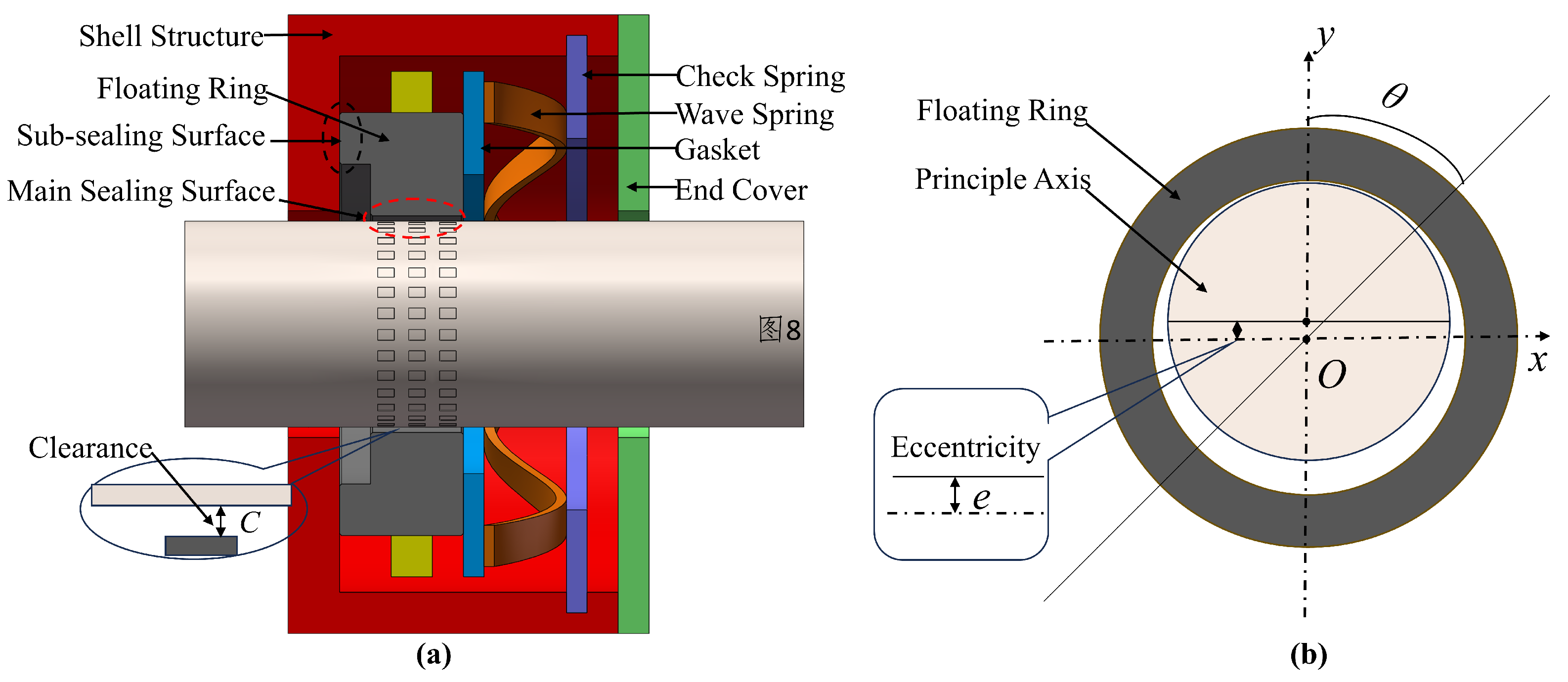
2.1. Working Principle

A floating ring seal, as illustrated in Figure 1a, primarily consists of a check ring, a gasket, a wave spring, a floating ring, and a shell. Initially, the floating ring is in touch with the outer wall of the shaft, with the maximum eccentricity between the ring and the shaft. As the seal operates, the dynamic pressure due to the wedge effect at high rotational speeds causes the floating ring to float upwards, creating a rigid fluid film between the ring and the shaft, which serves as the main sealing surface. Additionally, the high-pressure gas and the wave spring generate a force making the floating ring’s end face against the shell, forming a sub-sealing surface.
Adding texture holes on the outer surface of the shaft is an effective way to enhance the dynamic pressure effect of the floating ring seal. When the sealing equipment is working normally, the gas on the high-pressure side is brought into the texture hole by the pump suction effect. The medium gas is continuously compressed at the edge of the micro-hole, and a significant dynamic pressure effect is generated in the surrounding area, forming a thin and stiff air film between the dynamic ring and the static ring, thereby improving the performance of the floating ring seals.
This paper simplifies the floating ring seal as a rigid radial gas bearing, and uses the following Reynolds Equation (1) to solve the performance of the floating ring seal:
1 R 2 θ p h 3 p θ + z p h 3 p z = 6 µ U R θ ( p h )
The sealing cross-section of the floating ring forming an eccentricity with the rotor is shown in Figure 1b. The film thickness of the floating ring seal with surface texture can be expressed as:
h = c + e cos θ + h 1 + h 2
where c is the average gas film clearance, e is the eccentricity, and θ is the coordinate of the angle centered at the origin from the positive direction of the y axis. h 1 represents the height of surface roughness. h 2 is the film thickness caused by textures.

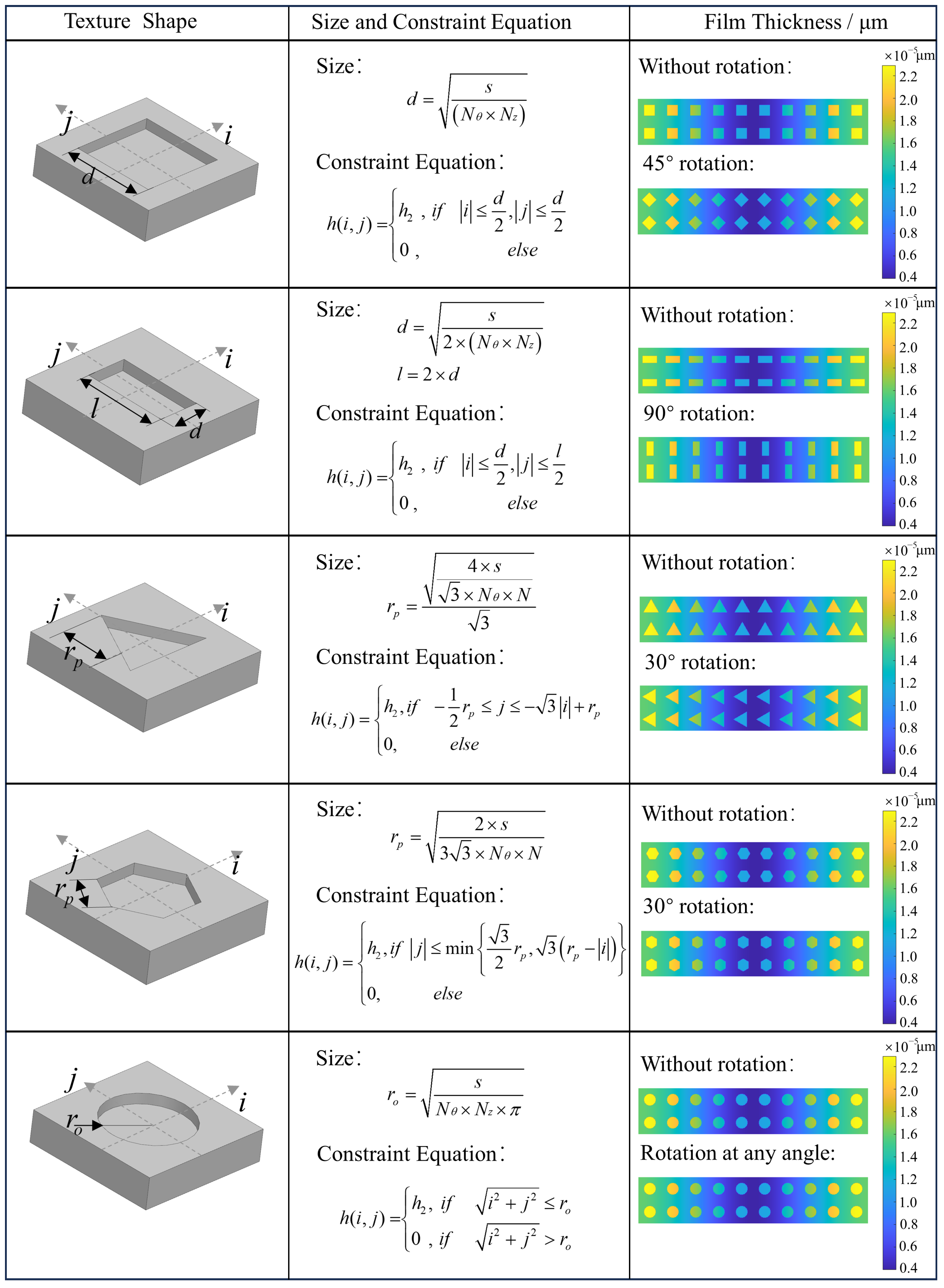
2.2. Surface Texture Model

In this paper, the effects of many different types of textures on the performance of floating ring gas seals are discussed. The shapes of texture shapes include rectangle, triangle, ortho-hexagon, and circle. Rectangular textures involve rectangular types with different ratios of length to width. Circular textures involve different ratios of long axis to short axis. For these different shapes of textures, the effects of texture depth, texture angle, and texture area ratio on the performance of the floating ring seal were analyzed.
The fundamental design scheme for different types of textures is shown below.
① Set the number of texture distribution in the circumferential and longitudinal directions;
② Set the ratio of textured area on the surface of the rotor axis;
③ Set a defined shape of the texture, e.g., define its aspect ratio for a rectangle;
④ Set the remaining parameters, including texture depth and angle.
With the steps ① ②, the area of a single texture can be calculated. For textures with a defined shape by steps ③, the defined edge length or radius can be calculated. The region in which each of the textures are distributed on the surface is determined by step ①. A new coordinate system is established in each region and the constraint equations for the shape of the texture are constructed from the known parameters. The direction angle of the texture is set in the new coordinate system. Under this design scheme, the shape and size of the texture can be easily modified. When the area ratio of the surface texture increases, the corresponding edge length or radius of a single texture will be larger, and the gap between the surface textures will be smaller. At the end of this subsection, the coordinates, shape constraint functions, and shape illustrations of the texture are shown in Figure 2.

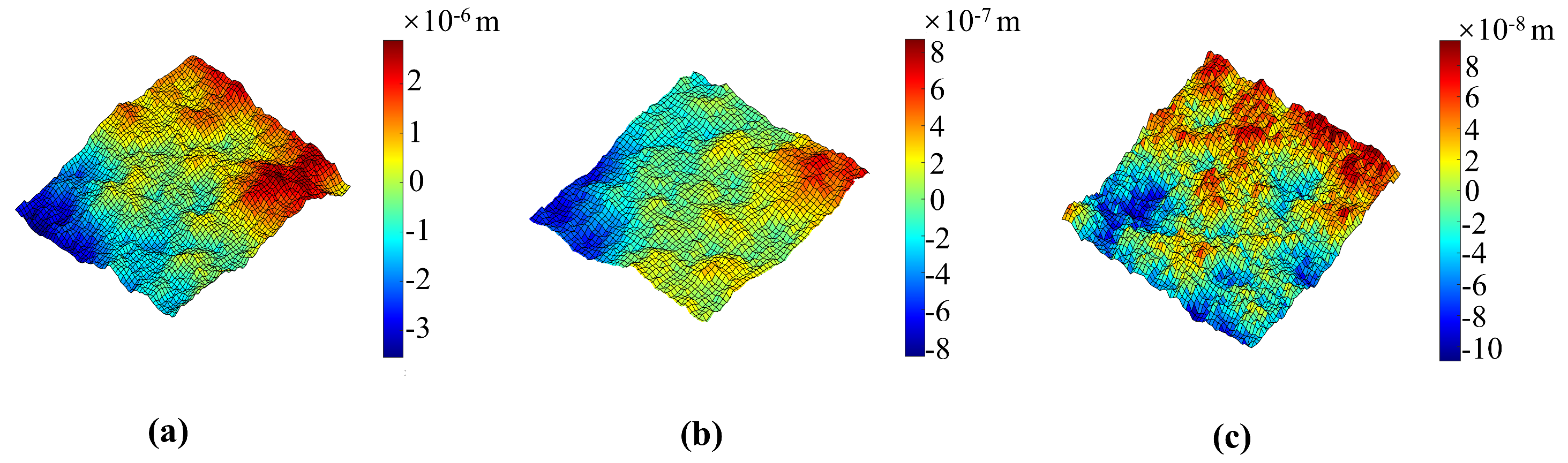
2.3. Surface Roughness Model

During the machining process of the floating ring seals, the sealing surface and journal surface will produce small spacing and tiny peaks and valleys, forming a surface roughness. Different machining methods will produce rough surfaces with different characterization properties. A closer look at a rough surface reveals that it is also statistically similar, while having scale-free properties under scale transformations. Fractal theory can capture the different sizes and attendant properties of solid surfaces and can be used to model the micro-scale structure of rough surfaces.
The main idea of adding the surface roughness is as follows: We refer to the equations of the fractal roughness model and use the computer to randomly generate the height matrix of the fractal roughness surface, and then superimpose the height value of the fractal roughness surface to the thickness of the sealing film, and finally, put the thickness of the sealing film into the iteration of the main program to obtain the sealing performance parameters.
It is feasible to use the theory of fractals to study rough surfaces. Its 3D functional model [21] is expressed as follows:
Z x , y = n = 1 C n γ ( 3 D s ) n sin [ γ n ( x cos B n + y sin B n ) + A n ]
where C n is a random value from a normal distribution with a mean of 0 and a variance of 1; A n and B n are mutually independent and uniformly distributed random numbers in the interval [0, 2 π ]; D s is the theoretical fractal dimension ( 2 < D s < 3 ) ; the characteristic parameter γ is a constant greater than 1, which usually takes the value of 1.5; n is the number of natural sequences.
A typical function commonly used to generate random fractal surfaces is given by the following equation [22,23,24,25]:
z ( x , y ) = C m = 1 M n = 0 n max γ ( D 3 ) n × cos ϕ m n cos 2 π γ n x 2 + y 2 1 / 2 L × cos ( tan 1 ( y / x ) π m M ) + ϕ m n
C = L G L ( D 2 ) ln γ M 1 / 2
where C is the height coefficient of the surface, D is the fractal dimension, and a larger fractal dimension D represents a denser rough surface profile. ϕ m n is a series of random phases between 0 and π , γ controls the frequency density in the surface contour, M is the number of spatial undulations, L is the size of the simulated image, and G is the feature scale parameter.
In the actual simulation, n m a x cannot be taken to infinity, and its value is taken as Equation (6):
n m a x = log L max / L min log γ
where L max is the sampling length, L min is determined by the instrument resolution, and · means rounding down the nearest integer.
Fractal roughness surface characteristics depend mainly on the parameters G and D. The fractal roughness G is a frequency-independent height scale parameter that determines the specific dimensions of the rough surface—the rougher the surface the higher the value of G [26]. The fractal dimension D determines the proportion of high-frequency components and low-frequency components in the surface profile. Thus, a smaller value of D indicates that low-frequency components are more dominant in the surface profile. When the fractal dimension D is a fixed value, the higher the value of fractal roughness G, the smoother the topology [27]. Taking the fractal roughness G = 5.5 × 10 11 , the fractal rough surfaces for different values of fractal dimension are shown in Figure 3. It can be seen that the fractal dimension affects the roughness of the fractal surface. The smaller the fractal dimension D, the more complex the variation in the surface contour and the rougher the surface will be [28]. From the comparison in Figure 3, we can see that the height of the surface roughness gradually increases as the fractal dimension decreases. From Table 1, we can see that both the arithmetic mean deviation and the maximum height of the profile increase as the fractal dimension decreases.
In fact, different values of G and different values of fractal dimension D can be taken one-by-one to analyze the results. However, the focus of this research is on the optimization of the texture on the floating ring seal, and the study of roughness is an extension and exploration based on this. It has to be admitted that the rough surface generated is probably not the real topography of the surface of the floating ring seal material. When G = 5.5 × 10 11 and the fractal dimension is taken as 2.5–2.7, the magnitude of the generated surface roughness is just at the micrometer level. These values are used and it is found that the generated surface topography is able to optimize the performance of the floating ring seal, and such a surface topography is selected and combined with the surface texture for further analysis of the floating ring seal.

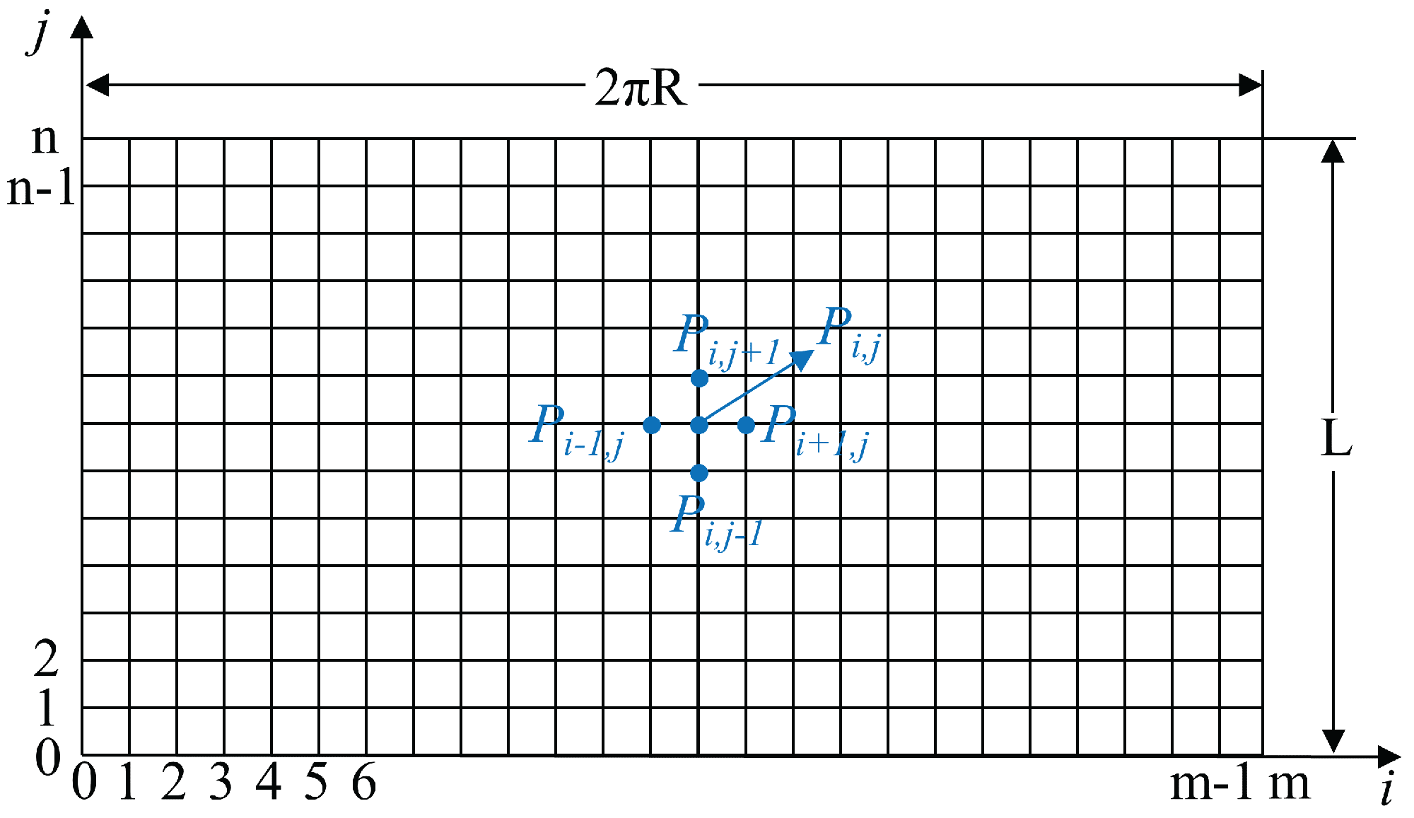
2.4. Differential Grids and Iteration

The numerical method used in this paper is the finite difference method, whose basic idea is to divide the solution field into orthogonal grids and use central difference formulas to substitute into the differential equations. The differential equations obtained are then solved by a computer using a successive over-relaxation (SOR) iteration method [29]. This approach is particularly useful for solving partial differential equations in two or three dimensions, and it has been widely applied in many scientific and engineering fields, such as heat transfer, fluid dynamics, and electromagnetic analysis. The approach for solving the problem is as follows: firstly, the Reynolds equation is simplified to a dimensionless form. Secondly, the dimensionless Reynolds equation is discretized and differentiated to obtain the difference equation. Finally, the SOR method is used to solve the difference equation.
The dimensionless Reynolds equation is presented as follows:
R 2 L 2 3 H H z ¯ p ¯ z ¯ + R 2 L 2 2 p ¯ z ¯ 2 + 3 H H θ p ¯ θ + 2 p ¯ θ 2 = 2 Λ p a p H 3 H 2 p ¯ θ + p ¯ H θ
where the symbols ( θ , z ) are coordinates in the circumferential and axial directions, Λ = 6 µ ω p a R c 2 are the seal coefficients, and the dimensionless quantities are expressed with z ¯ = z L , p ¯ = p 2 p a 2 , H = h c .
The grid of the 2D flow field in the floating ring seal is shown in Figure 4. Δ z is the step size in the differential grid axis direction, where Δ z = L / ( n 1 ) . Δ θ is the step size in the differential grid circumferential direction, where Δ θ = 2 π / ( m 1 ) . i and j represent the circumferential and axial grid positions of the floating ring seal, respectively.
By using the following central difference scheme, the discrete difference of the continuous 2D Reynolds equation is differentiated and solved iteratively by computer. The difference schemes are shown as follows:
2 p ¯ z ¯ 2 = p ¯ i , j + 1 2 p ¯ i , j + p ¯ i , j 1 Δ z ¯ 2 , 2 p ¯ θ 2 = p ¯ i + 1 , j 2 p ¯ i , j + p ¯ i 1 , j Δ θ 2 , p ¯ z ¯ = p ¯ i , j + 1 p ¯ i , j 1 2 Δ z ¯ ,
p ¯ θ = p ¯ i + 1 , j p ¯ i 1 , j 2 Δ θ , H z ¯ = H i , j + 1 H i , j 1 2 Δ z ¯ , H θ = H i + 1 , j H i 1 , j 2 Δ θ .
By substituting the central difference scheme into the dimensionless Reynolds Equation (7), the differential Reynolds equation is obtained. The simplified difference equation for solving the dimensionless pressure of the floating ring seal is obtained as follows:
A i , j p ¯ i 1 , j + B i , j p ¯ i + 1 , j + C i , j p ¯ i , j + D i , j p ¯ i 1 , j + E i , j p ¯ i , j + 1 = F i , j
For the dimensionless pressure p ¯ , the value of its n + 1 times iteration can be calculated from the value of the n times iteration. The equation is presented as follows:
p ¯ i , j n + 1 = A i , j p ¯ i 1 , j n + 1 + B i , j p ¯ i + 1 , j n + D i , j p ¯ i , j 1 n + 1 + E i , j p ¯ i , j + 1 n F i , j C i , j
The iteration stops when the dimensionless pressure p ¯ satisfies the following convergence condition:
i = 1 m j = 1 n Δ p ¯ i , j p ¯ i , j 2 10 6
The boundary conditions are presented as follows:
p ( z = 0 , θ ) = p high p ( z = L , θ ) = p low p ( z , θ = 0 ) = p ( z , θ = 2 π )
where p low is the pressure of the low-pressure end of the floating ring seal, and p high is the pressure of the high-pressure end of the floating ring seal. The total procedure for solving the sealing performance is shown in Figure 5.

2.5. Performance Evaluation
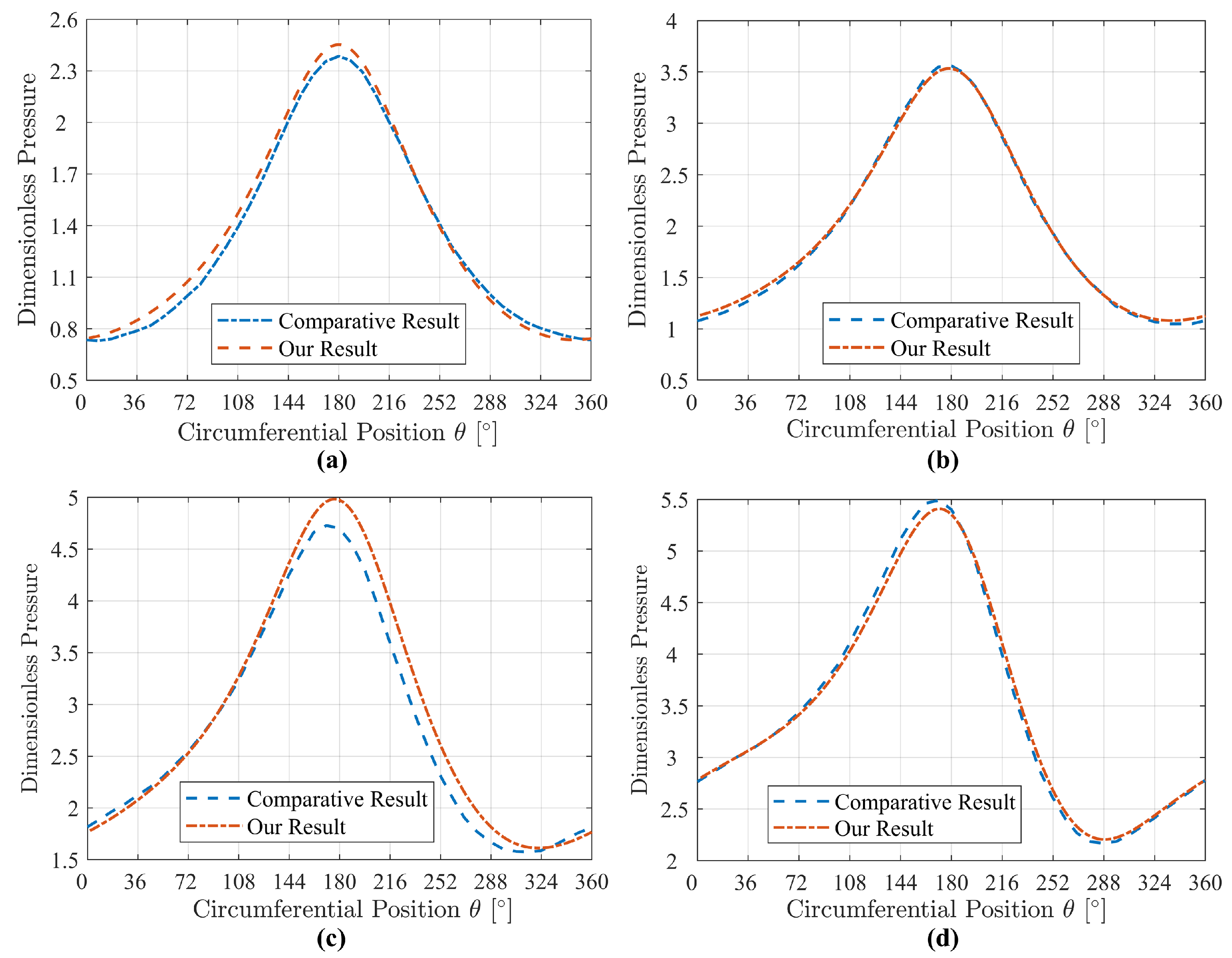
There is no contact between the floating ring and the rotating shaft in normal operation, resulting in low frictional wear. If the buoyancy force is insufficient, the floating ring will struggle to rise completely, resulting in contact with the rotor shaft, which can cause severe wear and significantly impact the performance and service life of the floating ring seal. Gas leakage is an important indicator of the performance of a floating ring gas seal. The smaller the gas leakage the better, which means a better seal and more efficient operation of the equipment. In practice, no leakage at all is unattainable, and there will always be a certain amount of gas leakage. If the leakage is too large, it will not only reduce the operating efficiency of the equipment, but may also cause pollution to the environment.
Through the coupled solution of the Reynolds equation and the film thickness equation, the pressure distribution of the gas film in the floating ring seal is obtained, and the seal gas film performance parameters are calculated.
The gas film dimensionless buoyancy force w ¯ for a floating ring seal is calculated as:
w ¯ = w ¯ x 2 + w ¯ y 2
where w ¯ x and w ¯ y are, respectively, the dimensionless buoyancy force in the x- and y-directions with the formula:
w ¯ x = 0 1 0 2 π p ¯ θ , z ¯ 1 sin θ d θ d z ¯ w ¯ y = 0 1 0 2 π p ¯ θ , z ¯ 1 cos θ d θ d z ¯
The air film buoyancy force is w = p a R L w ¯ . The gas leakage Q of a floating ring seal is calculated by the formula:
Q = 0 2 π R ρ h 3 12 µ p z z = L d θ
The ratio of the air film buoyancy to the leakage of the floating ring seal is introduced to better measure the performance of the floating ring seal, and the formula for the buoyancy leakage ratio is k = Q w .
In addition, this study considers calculating the friction to provide a comprehensive measure of the improved performance of the floating ring seal. The components of friction in the horizontal and vertical directions are shown in Equation (15):
T x = 0 1 0 2 π ( Λ 6 1 h h 2 p θ ) sin θ d θ d z T y = 0 1 0 2 π ( Λ 6 1 h h 2 p θ ) cos θ d θ d z

3. Validation

This paper compares and validates the results of Ma et al. [30] on floating ring cylinder surface air film seals. Their results were subsequently verified in the paper of Chen [31] and the paper of Xu [28]. The parameters of the floating ring cylinder surface air film are shown in Table 2.
A comparison between the results of this paper and Ma et al. [30] is shown in Figure 6. The curves in the figure show the dimensionless pressure of the cross-section in the seal at pressures of 0.11, 0.20, 0.32, and 0.45 MPa at the high-pressure end, respectively. From Figure 6, it can be seen that the trend of the dimensionless pressure in the mid-section obtained in this study is basically consistent with the literature for different conditions. The differences in the values are also very small, with the maximum difference not exceeding 5 % . The above results and analyses show that the solution methodology of this study for floating ring seals is well supported and the results are relatively accurate.

4. Result and Discussion
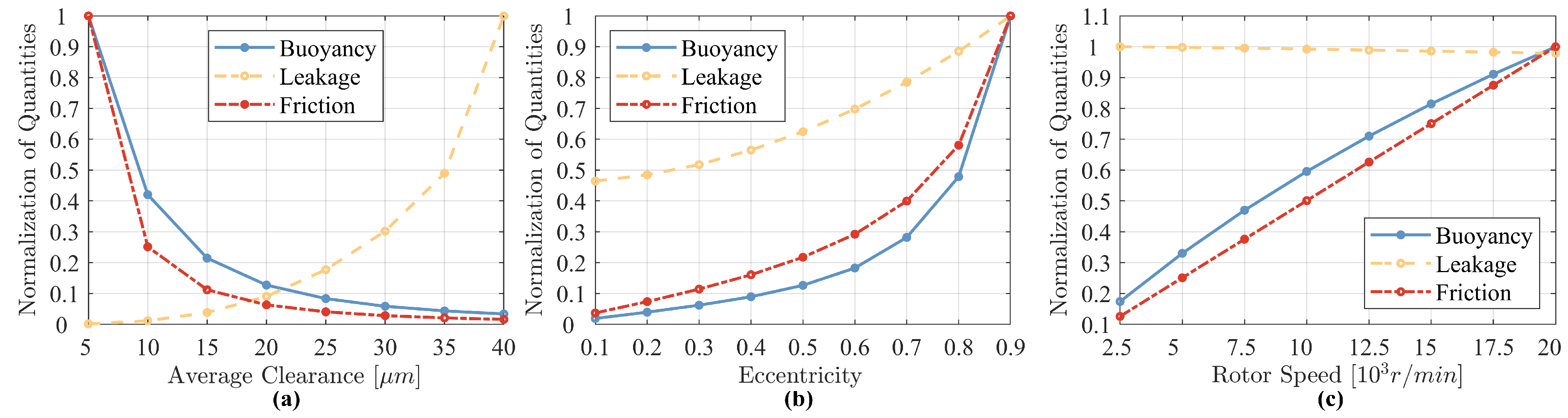
4.1. Seal Mechanism

Figure 7 shows the effect of parameters like rotor speed, average clearance, and eccentricity on the seal’s performance in terms of buoyancy, leakage, and friction. The vertical axis is the magnitude of the value of the floating ring seal performance parameters after the reduction to a dimensionless form and normalization. From Figure 7a, it can be seen that as the average gas film clearance of the floating ring seal increases, the gas film buoyancy and friction decrease and the gas leakage increases rapidly. When the clearance is large, the tendency of the gas film buoyancy force and friction force to decrease is relatively small. When the gas film clearance increases, the hydrodynamic effect becomes weaker leading to a reduction in the pressure of the gas in the sealing gap [32], which results in a corresponding reduction in the gas film buoyancy and friction. Due to the increase in the gas film clearance, the leakage channel of the gas in the sealing gap becomes looser [6], which leads to a rapid increase in the gas leakage.
From Figure 7b, it can be seen that as the eccentricity of the floating ring increases, the gas film buoyancy and friction increase dramatically and the gas leakage increases consequently. The increase in the eccentricity results in a stronger converging wedge between the rotor and the floating ring. At the same time, the minimum air film thickness decreases, and the dynamic fluid pressure in the wedge region increases dramatically, resulting in a sharp increase in the air film buoyancy and friction. The increase in eccentricity results in an uneven distribution of the sealing gap, which leads to larger leakage channels in the low-pressure region and a corresponding increase in leakage.
Figure 7c illustrates the variation in seal performance parameters with rotor speed, where both the gas film buoyancy and friction increase accordingly with increasing speed, while the gas leakage decreases slightly. It is easy to understand that as the rotational speed increases, the hydrodynamic effect increases [32], resulting in an increase in the pressure of the air film inside the seal ring, which correspondingly results in an increase in the air film buoyancy [4]. At the same time, due to the viscous effect, the friction between the air film and the surface increases accordingly. As can be seen from the variation in leakage, the leakage is mainly related to the dimension of the leakage channel. The pressure gradient at the end face does not change much, making it stable for the leakage.

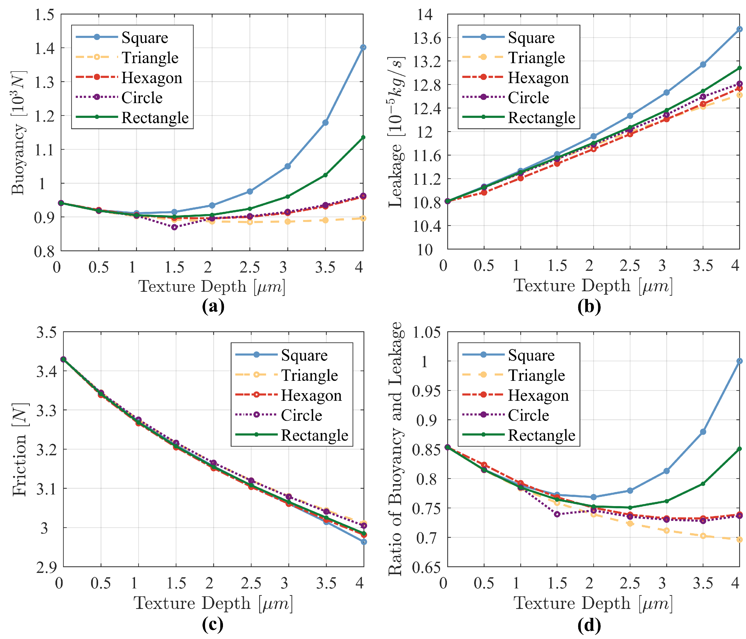
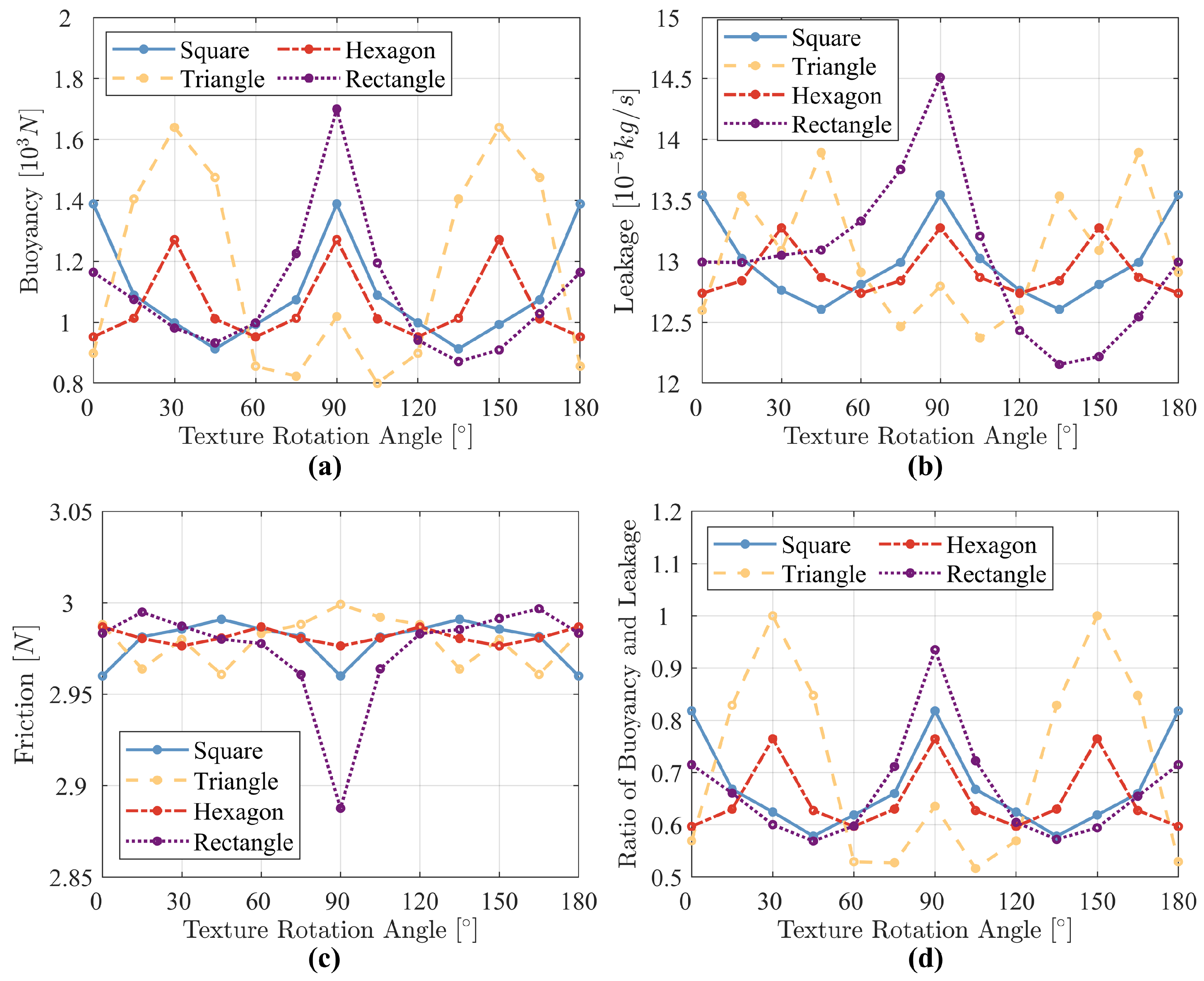
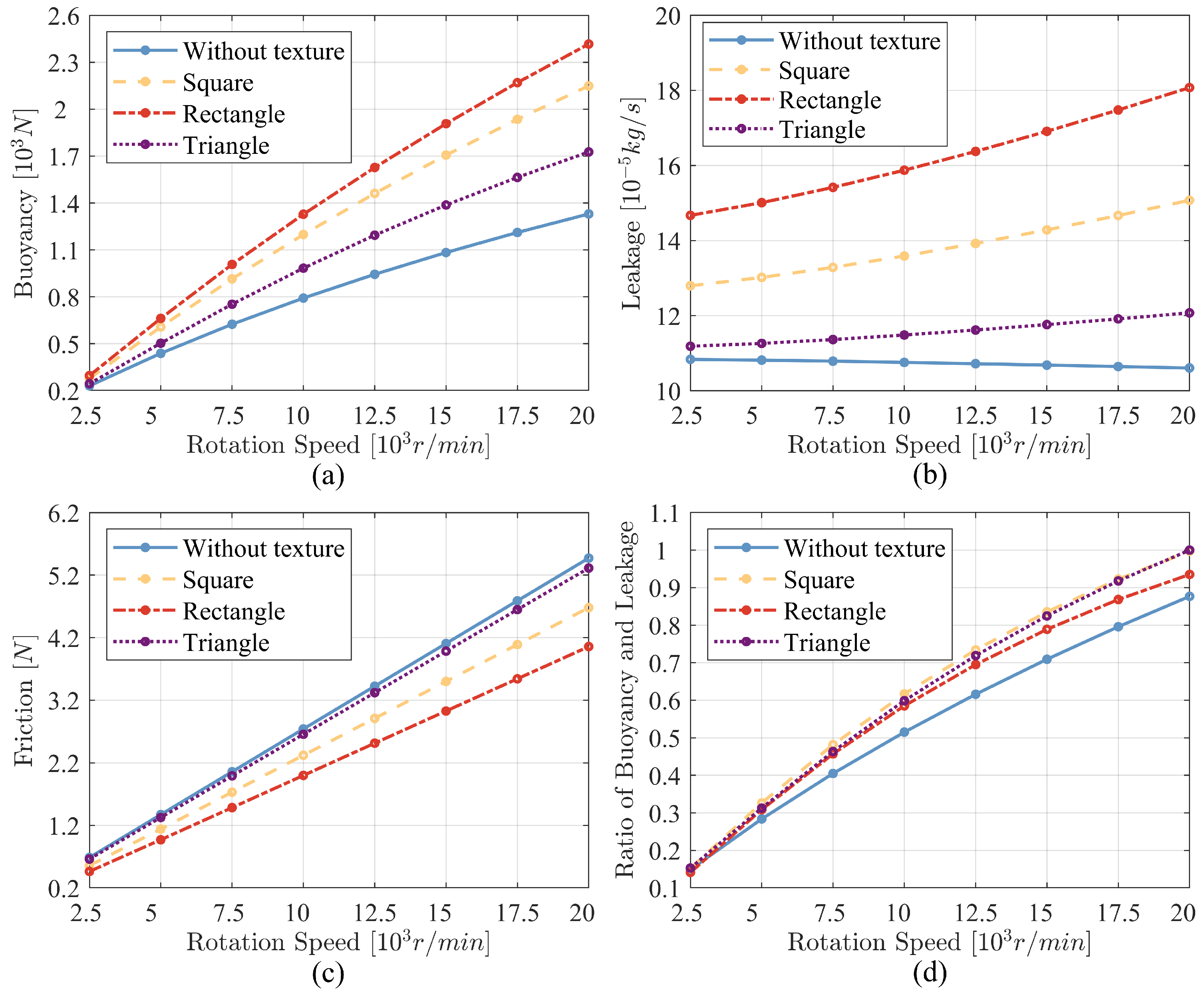
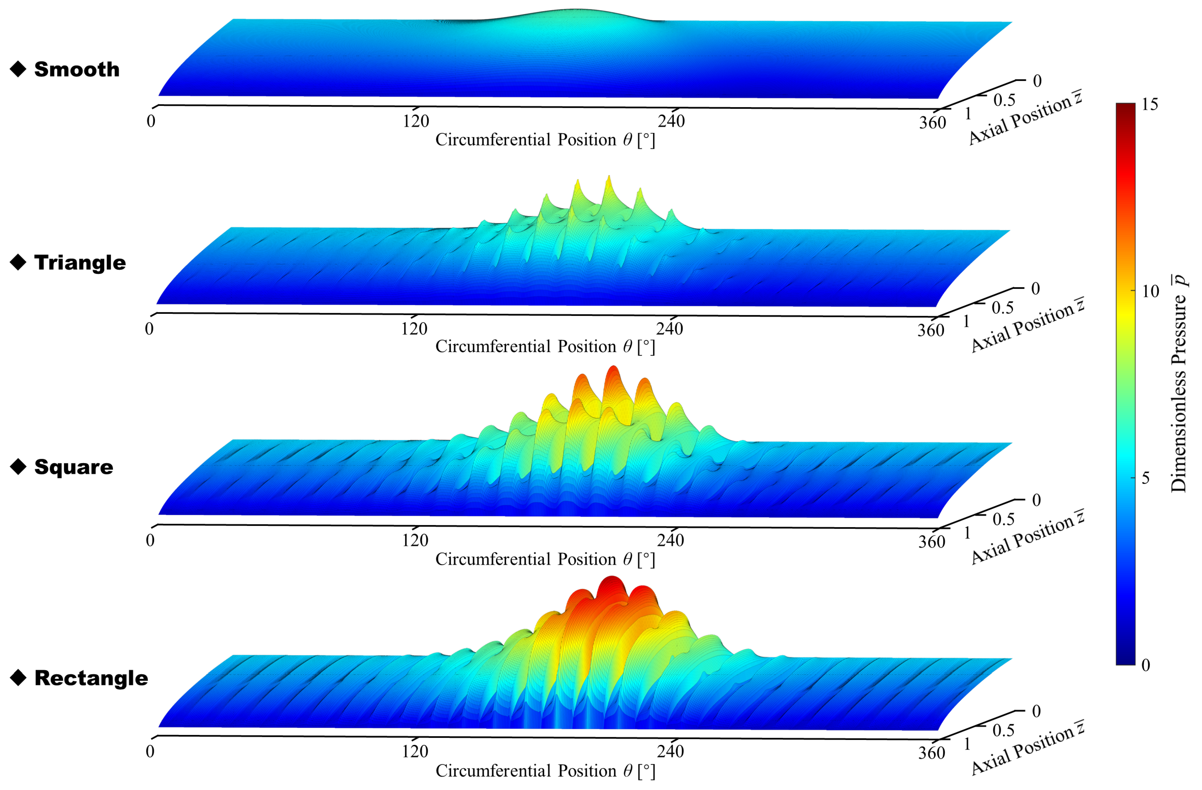
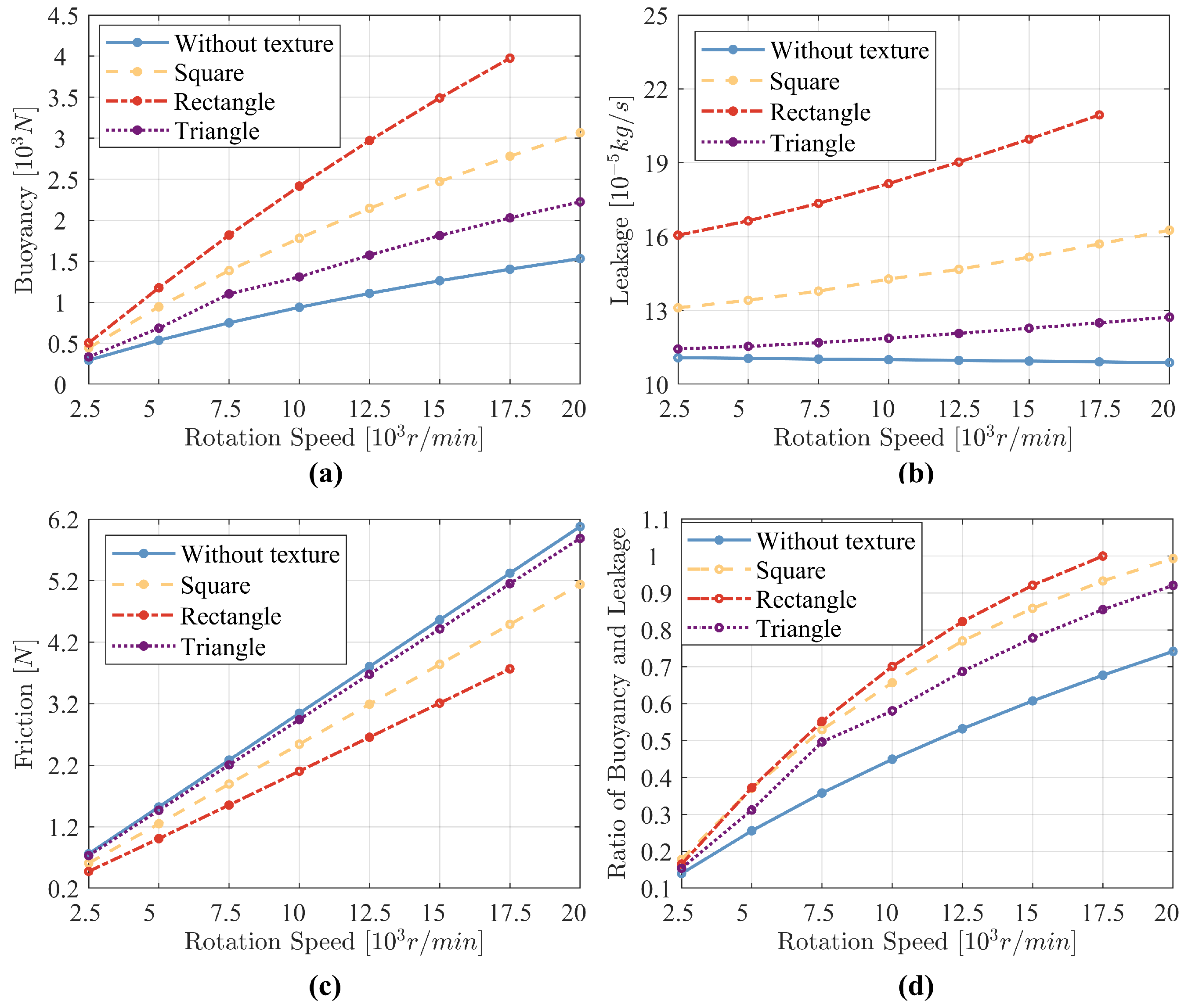
4.2. Effect of Texture

In this subsection, we calculate the effect of five different shapes of textures as well as their depth, rotation angle, and area ratio on the performance of the floating ring seal. The parameters of the textures are shown in Table 2 and Table 3.
Figure 8 shows the effect of five texture shapes and their depths on the performance of the floating ring seal, where the horizontal coordinate is the variation in the depth of the surface texture and the vertical coordinate is the variation in the performance parameters of the floating ring seal, which include the gas film buoyancy force, gas leakage, friction force, and float-leakage ratio.
From Figure 8a, it can be seen that the air film buoyancy force decreases and then increases as the depth of the texture increases. The increasing trend is more drastic for squares and rectangles, the trend is almost the same for circles and square hexagons, and triangles bring the weakest effect. At a texture depth of 4 µ m, compared to the non-textured surface, all other shapes of textures, except for the triangular textures, can enhance the gas film buoyancy, and the square texture improved the buoyancy by up to 91.5%. As can be seen in Figure 8b, the five shapes of textures lead to an increase in the gas leakage of the floating ring seal as the depth of the surface texture increases, with the square bringing the best increase and the rectangle the second best. The square texture increases the leakage by up to 34.66%. Figure 8c demonstrates the trend of the gas viscous friction, with the friction decreasing accordingly as the depth of the texture increases. Figure 8d shows the variation in the ratio of buoyancy and leakage. From Figure 8d, it can be seen that the trend is similar to that of the buoyancy, since the change in leakage is linear overall. Compared to the floating ring seal without texture, the square texture with a depth of 4 µ m generates a significant improvement in the float-leakage ratio.
A comprehensive comparison of the four graphs shows that when the depth of the texture is more than 2 µ m, the difference in the effect of the texture shape on the performance of the floating ring seals gradually increases. Especially, the gas film buoyancy and gas leakage of the square texture increase substantially. The increase in those two quantities is smaller for the rectangular texture. The change in the ratio of the buoyancy and leakage then illustrates that the enhancement of buoyancy is greater for square and rectangular textures compared with the leakage.
The texture can form tiny concave–convex structures [33] on the surface of the material, which leads to strong dynamic pressure effects [34] and reduces the actual contact area [35]. As the depth of the texture increases, the average thickness of the air film increases, which causes the sealing gap fluid channel to widen, enhancing the circulation of the lubricating air film and increasing leakage.
Figure 9 illustrates the effect of the rotation angle of the texture on the sealing performance of the floating ring seal, where the horizontal coordinate is the angle of rotation of the texture from 0° to 180°, since the shapes of the textures are all centrosymmetric. The discussion in this figure does not involve circular textures as circles have rotational invariance.
As can be seen from Figure 9a, for the square texture, the increase in the buoyancy force generated by the texture is greatest when no rotation occurs or when the angle of rotation is an integer multiple of 90°. Meanwhile, it can be seen from Figure 9b that the leakage in this case is also the largest for the square textures. However, we can find that the change in leakage is relatively small compared to the buoyancy force. For the square texture, the maximum change in the floating force is 52.01% while the maximum change in the leakage is 7.46%. This is also illustrated in Figure 9d, where the buoyancy dominates the trend of the buoyancy-leakage ratio. From Figure 9c, it can be found that the effect of the rotation angle of the texture on the friction is weak. Except for the case where the rectangular texture is rotated by 90°, the changes in friction caused by rotation angle are all within 1.35%. The reason for this special case for rectangles is probably because it is relatively less symmetrical. On the whole, the texture rotation angle has a relatively large effect on the gas film buoyancy force of the floating ring seal. The overall performance of the floating ring seal is optimized when the square texture is not rotated, the triangular texture is rotated by 30°, or the rectangular texture is rotated by 90°.
The effects of different texture area percentages on the performance of the floating ring seal are shown in Figure 10, which involves the textures in area percentages from 0 to 50%. From Figure 10b,c, it can be found that with increase in the percentage of texture area, the leakage of the floating ring seal is increased accordingly, and the friction is reduced accordingly. The reason for this phenomenon is similar to the situation of Figure 8, where the increase in the area of the texture increases the lubrication film [35] on the seal surface, and also increases the leakage channel of the fluid [34], thus reducing the friction and increasing the leakage. For the proposed shapes of textures, the effect of the area ratio of the texture on the buoyancy force is not consistent. From Figure 10a, it can be seen that both square and rectangular textures generate more buoyancy as the area ratio of the texture increases. The circular texture also provides the effect of buoyancy enhancement in general, but the trend of the change is tortuous. Changes in the area ratio of the triangular and hexagonal textures have a weak effect on the buoyancy force, which gradually decreases when the area ratio is larger. In addition, when the area ratio of the texture reaches 40%, the buoyancy force generated by the rectangular texture falls in a faulty manner. By calculation, the gap between the circumferential textures in this case is only 12.41% of the length of a single texture. The texture distribution with depth is too dense, making the effect equivalent to increasing the sealing clearance.
Overall, the effect of square and rectangular textures on the buoyancy of the floating ring seal is more significant, with an increase in either the depth or area ratio of the texture resulting in an increase in its buoyancy. Other shapes have a weaker effect on the buoyancy without angular rotation. For all shapes of textures, an increase in the depth or area ratio of the textures leads to a decrease in friction and an increase in leakage. The degree of friction reduction is close for different shapes of textures. Comparatively speaking, the effect of variation in the percentage of texture area on the floating ring seal is more significant than that generated by variation in the depth of the texture. Different shapes of textures have their optimal rotation angles: 0° for square textures, 90° for rectangular textures, and 30° for triangular textures. In general, the square texture with a rotation angle of 0° and an area ratio of 0.25, the rectangular texture with a rotation angle of 90° and an area ratio of 0.4, and the triangular texture with a rotation angle of 30° and an area ratio of 0.05 give the best results. In the next subsection, the folded three types of textures are further analyzed and discussed.
The results of the effect of no texture and three types of textures, as shown in Table 4, on the performance of the floating ring seal at different rotational speeds are shown in Figure 11. It can be seen from Figure 11a that all three types of textures can contribute to increasing the buoyancy force of the floating ring seal, and the increase is greater at higher rotational speeds. The specific rectangular textures generate the largest increase in buoyancy force, which reaches 81.2% at a rotation speed of 20,000 r/min. However, it can be noticed from Figure 11b that this particular rectangular texture increases the amount of leakage while enhancing the buoyancy. The textures increase the leakage with increasing speed compared to the no texture. But the specific triangular texture keeps the increase in leakage within a small range. This specific triangular texture increases the buoyancy by 28.02% when the rotation speed is 15,000 r/min and the leakage increases by only 10.08%. Figure 11c illustrates the variation in friction with rotational speed for four cases. It is obvious that the friction increases as the rotational speed increases and all three types of textures reduce the friction to a certain extent as compared to no texture. Taking into account the variation in buoyancy and leakage, it can be noticed from Figure 11d that all three specific textures have a good effect. Among them, the specific square texture and the specific triangular texture are slightly better than the rectangular texture.
Figure 12 shows the dimensionless pressure distribution for the case of a smooth surface and three types of surfaces with the aforementioned textures. From the figure, it can be found that all three textures enhance the peak air film pressure compared to the smooth surface. Among them, the peak air film pressure with rectangular texture is the largest. This is in accordance with the results of Figure 11. In addition, it can be noticed that the pressure in the texture region is lower than that in the non-texture region, but the texture makes the gas film pressure overall higher than that in the case of a smooth surface. And because of the increased pressure peaks, it leads to an increase in the gas pressure gradient making the gas leakage increase.
Overall, the specific rectangular texture can be prioritized when buoyancy enhancement is most important. The specific triangular texture can be preferred when buoyancy enhancement is of high importance while at the same time strictly preventing an increase in leakage. In addition, this rectangular texture is the most effective in terms of reducing friction. The textures can be selected according to the requirements of the operation.

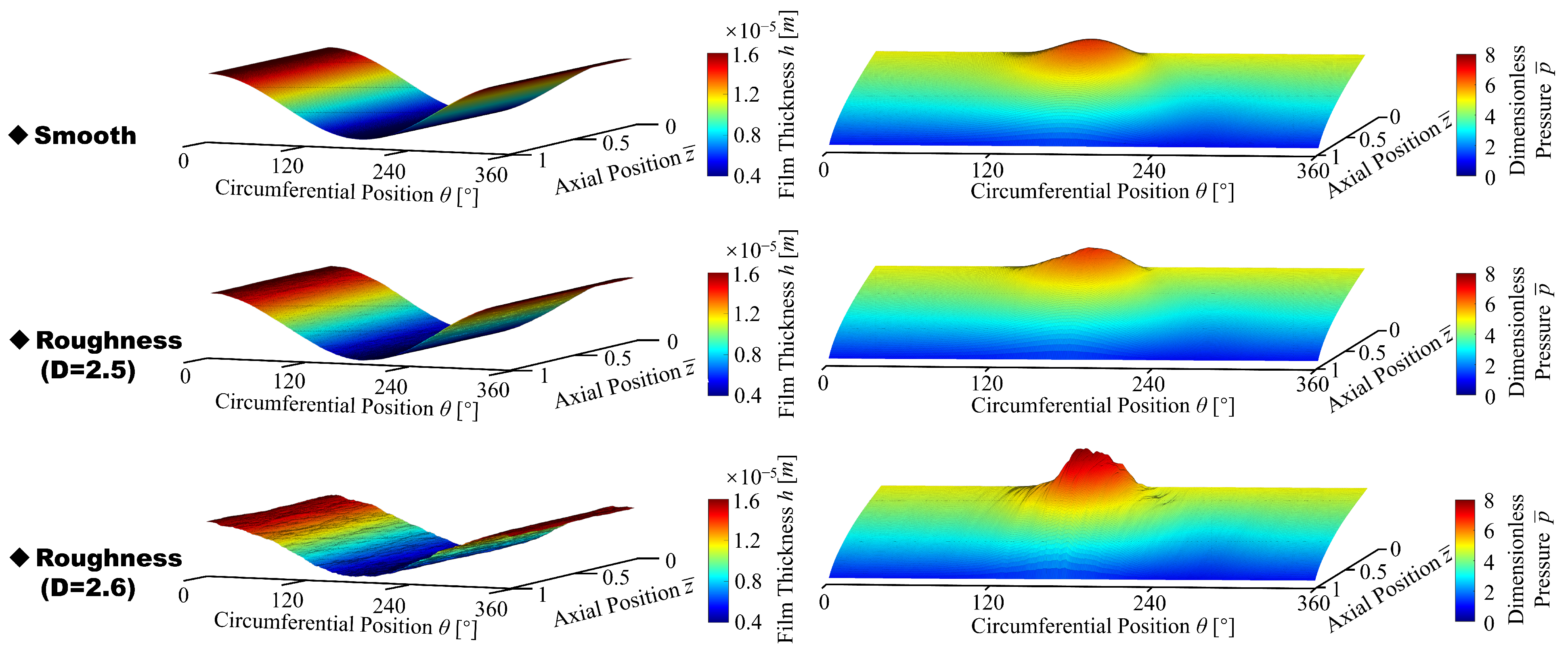
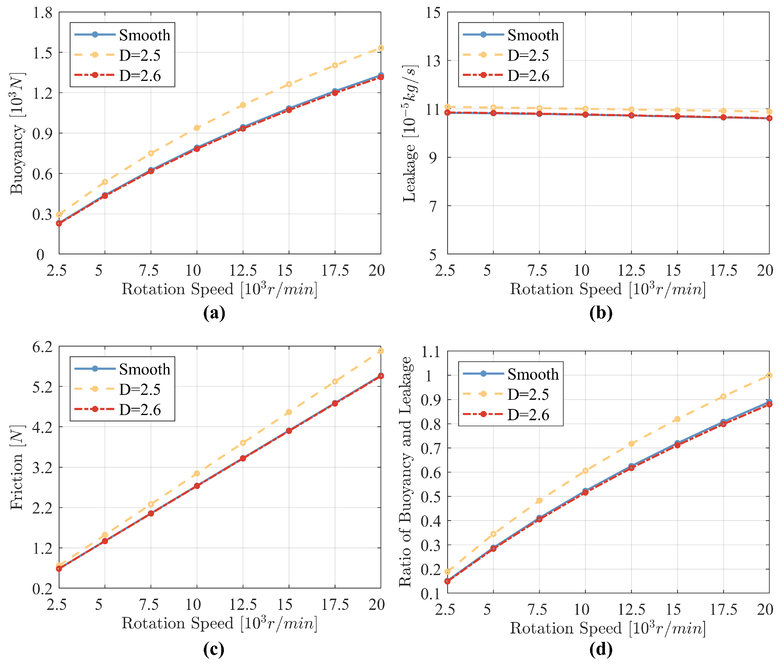
4.3. Effect of Texture with Roughness

Figure 13 shows the thickness and dimensionless pressure of the floating ring seal air film for a smooth surface and fractal rough surfaces with fractal dimensions D = 2.5 and D = 2.6 , respectively. It can be seen that the surface roughness is presented in the air film thickness, which is more pronounced when the fractal dimension D = 2.5 . This is because the arithmetic mean deviation is greater for fractal dimension D = 2.5 relative to fractal dimension D = 2.6 . At the same time, we can see a significant increase in the pressure peak. The pressure comes from the dynamic pressure effect generated by the eccentricity of the floating ring, and the air film thickness is smaller at the position of the eccentricity of the floating ring, so the effect of roughness becomes more significant. The air film pressure of the floating ring seal with surface roughness is enhanced. When the fractal dimension D = 2.6 , the fractal roughness surface has less effect, because the order of magnitude of its height is negligible compared to the air film thickness.
It can also be seen from Figure 14 that when the fractal dimension of the fractal rough surface D = 2.6 , the parameters such as air film buoyancy, leakage, and friction of the floating ring seal are close to those when the surface is smooth. When the fractal dimension D = 2.5 , the buoyancy of the floating ring seal is somewhat enhanced at different speeds, while the gas leakage is slightly increased. This is consistent with the air film pressure being boosted in Figure 13. The air film buoyancy force increases as the rotational speed increases. The buoyancy-leakage ratio is enhanced overall, and the greater the rotational speed the greater the enhancement. It can be seen that a certain surface roughness has an improving effect on the performance of the floating ring seal. This is consistent with the conclusions of [36]. It can be found that the surface roughness has a similar effect as the surface texture. However, as can be seen from Figure 14c, the surface roughness increases the friction of the floating ring seal, in contrast to the surface texture.
Therefore, the effect of certain textures with surface roughness on the performance of the floating ring seal is discussed and the results are shown in Figure 15. The texture parameters are shown in Table 4 and the fractal dimension D = 2.5 . Comparison of Figure 11 and Figure 14 shows that the textures with a certain roughness boost more buoyancy and only slightly increase leakage. Compared to a smooth surface, when the rotation speed is 15,000 r/min, the triangular textures increase buoyancy by 28.02% and increase leakage by only 10.08%. As a comparison, the triangular textures with roughness increase buoyancy by 67.39% and leakage increases by 14.92%. The rectangular surface textures improve buoyancy by 183.29% at 17,500 rpm when the surface of the floating ring seal is rough. Figure 11c illustrates the variation in friction with rotational speed for four cases. From comparison of the buoyancy-leakage ratio, the textures with a certain roughness generate a better enhancement effect on the floating ring seal. In addition, the surface roughness does not change the mechanism of the effect of textures, but affects the degree of the effect of the textures. The design of textures combined with surface roughness can be one of the means to enhance the performance of a floating ring seal. However, the process and cost of mechanically creating surface roughness need to be considered.

5. Conclusions

In summary, this work employed the finite difference method to iteratively solve the Reynolds equation for the sealing fluid, and then analyzed the effects of surface texture and surface roughness on the performance of floating ring seals. The effects of different surface textures and their parameters on the performance of floating ring seals are systematically presented and discussed. The key conclusions are summarized as follows:
① Increasing the clearance can reduce friction, but it will compromise buoyancy and increase leakage. Conversely, increasing the eccentricity can enhance buoyancy, but it will significantly increase friction and leakage. Moreover, the increase in rotational speed significantly boosts buoyancy and friction, with a negligible impact on leakage.
② For an arbitrarily shaped texture in this paper, the depth of the texture has a significant influence on the performance of the floating ring seal. The greater the depth of the texture, the greater the leakage and the lower the friction. The change in buoyancy caused by the depth is related to the shape. The greater the depth of the texture within a certain range, the better the overall performance of the floating ring seal.
③ The best angles for making the textures most effective are 30° for triangles and hexagons, 90° for rectangles, and 0° for squares.
④ An increase in the texture area leads to increased leakage and reduced friction. The square and rectangular textures exhibit a stronger effect, and as the texture area increases, the buoyancy force also increases significantly.
⑤ The textures mentioned in Table 4 can significantly enhance the performance of the floating ring seals. The specific rectangular texture shows the largest increase in buoyancy force, which reaches 81.2% at a rotation speed of 20,000 r/min. This specific triangular texture increases buoyancy by 28.02% when the rotation speed is 15,000 r/min and leakage increases by only 10.08%.
⑥ Appropriate surface roughness can serve to enhance the performance of the floating ring seal; the effect of texture is substantially enhanced when the floating ring seal surface is rough. The triangular textures mentioned in Table 4 with roughness increase buoyancy by 67.39% and leakage increases only by 14.92%.
Both optimized surface texture and surface roughness can contribute to enhancing the overall performance of floating ring seals, particularly in terms of buoyancy. The combination of surface texture and surface roughness is a promising direction that yields positive results. However, the rough surface simulated by the computer model is generated by randomization, and the feasibility of the process still requires further verification and experimental confirmation.

Author Contributions

Conceptualization, Z.H., Y.G. and J.S.; Methodology, Z.H., Y.G., L.J., Y.Z. and H.W.; Validation, Y.G.; Data curation, Y.G.; Writing – original draft, Y.G.; Writing – review & editing, Z.H., Y.G., J.S., Ning Li, L.J., Y.Z. and H.W.; Visualization, Y.G.; Supervision, Z.H., J.S. and N.L.; Funding acquisition, Z.H. All authors have read and agreed to the published version of the manuscript.

Funding

This research was funded by the Fundamental Research Funds for the Central Universities grant number 3122019178, the Tianjin Municipal Science and Technology Bureau Science and Technology Plan Project grant number 23JCYBJC00110 and the Civil Aircraft Special Scientific Research Project initiated by the Ministry of Industry and Information Technology.

Data Availability Statement

The original contributions presented in the study are included in the article, further inquiries can be directed to the corresponding author.

Acknowledgments

The authors would like to thank the anonymous referees for their careful reading and valuable comments to this paper.

Conflicts of Interest

Author Jiaxin Si and author Ning Li are employed by the company AECC Hunan Aviation Powerplant Research Institute. The remaining authors declare that the research was conducted in the absence of any commercial or financial relationships that could be construed as a potential conflict of interest.

Nomenclature

Atextured area
A n random numbers in the interval [0, 2 π ]
bposition of the shaft surface
B n random numbers in the interval [0, 2 π ]
cradial clearance, m
Cheight coefficient of the surface
C n a normally distributed random variable with a mean of 0 and variance of 1
dlengths of square textures; the width of the rectangular texture, m
Dfractal dimension
D s theoretical fractal dimension
eeccentricity, m
Gfeature scale parameter
hgas film thickness, m
h 1 distribution of depth of texture
h 2 distribution of depth of surface roughness
h d depth of texture, m
Hdimensionless film thickness
kratio of buoyancy and leakage, N· kg/s
llength of the rectangular texture, m
Lsize of the simulated image, m
L m a x sampling length, m
L m i n a number which is determined by the instrument resolution
mfrequency coefficient
Mnumber of spatial undulations
nfrequency coefficient
n m a x maximum frequency coefficient
pgas film pressure, Pa
p ¯ dimensionless film pressure
p a air pressure, Pa
p l o w pressure in the low-pressure side, Pa
p h i g h pressure in the high-pressure side, Pa
Qleakage, kg/s
Rradius of the rotating shaft, m
r p radius of the outer circle of a triangular or hexagonal texture, m
r o radius of the outer circle of a triangular or hexagonal texture, m
T x dimensionless friction component in the x-direction
T y dimensionless friction component in the y-direction
Ulinear velocity of rotating shaft, m/s
wbuoyancy of gas film, N
w ¯ dimensionless buoyancy of gas film, N
w ¯ x dimensionless buoyancy component in the x-direction
w ¯ y dimensionless buoyancy component in the y-direction
γ characteristic parameter
Λ seal coefficient
μ aerodynamic viscosity, Pa · m
ϕ m n a series of random phases between 0 and π
ρ gas density, kg/m3

References

  1. Xia, P.; Chen, H.; Liu, Z.; Ma, W.; Yang, B. Analysis of whirling motion for the dynamic system of floating ring seal and rotor. Proc. Inst. Mech. Eng. Part J J. Eng. Tribol. 2019, 233, 1221–1235. [Google Scholar] [CrossRef]
  2. Duan, W.; Chu, F.; Kim, C.H.; Lee, Y.B. A bulk-flow analysis of static and dynamic characteristics of floating ring seals. Tribol. Int. 2007, 40, 470–478. [Google Scholar] [CrossRef]
  3. Lee, Y.B.; Kim, C.H.; Duan, W.; Chu, F. Analysis of Leakage Flow and Dynamic Characteristics in Floating Ring Seals for High Pressure Turbopump. In Proceedings of the Turbo Expo: Power for Land, Sea, and Air, Barcelona, Spain, 8–11 May 2006; Volume 42401, pp. 1341–1349. [Google Scholar]
  4. Bae, J.H.; Kwak, H.D.; Heo, S.J.; Choi, C.H.; Choi, J.S. Numerical and experimental study of nose for Lox floating ring seal in turbopump. Aerospace 2022, 9, 667. [Google Scholar] [CrossRef]
  5. Shi, R.J.; Li, S.X.; Zhen, R.; Ma, L.j.; Zhang, J.B. Design method and research of high temperature gas floating ring seal with slightly variable gap. IOP Conf. Ser. Mater. Sci. Eng. 2021, 1081, 012005. [Google Scholar] [CrossRef]
  6. Anbarsooz, M.; Amiri, M.; Erfanian, A.; Benini, E. Effects of the ring clearance on the aerodynamic performance of a CO2 centrifugal compressors annular seal: A numerical study. Tribol. Int. 2022, 170, 107501. [Google Scholar] [CrossRef]
  7. Li, G.; Zhang, Q.; Huang, E.; Lei, Z.; Wu, H.; Xu, G. Leakage performance of floating ring seal in cold/hot state for aero-engine. Chin. J. Aeronaut. 2019, 32, 2085–2094. [Google Scholar] [CrossRef]
  8. Nagai, K.; Kaneko, S.; Taura, H.; Watanabe, Y. Numerical and experimental analyses of dynamic characteristics for liquid annular seals with helical grooves in seal stator. J. Tribol. 2018, 140, 052201. [Google Scholar] [CrossRef]
  9. Lu, X.; Andrés, L.S. Leakage and Rotordynamic Force Coefficients of a Three-Wave (Air in Oil) Wet Annular Seal: Measurements and Predictions. J. Eng. Gas Turbines Power 2019, 141, 032503. [Google Scholar] [CrossRef]
  10. Zhang, G.H.; Wang, G.L.; Liu, Z.S.; Ma, R.X. Stability Characteristics of Steam Turbine Rotor Seal System with Analytical Floating Ring Seal Force Model. In Proceedings of the Turbo Expo: Power for Land, Sea, and Air. American Society of Mechanical Engineers, San Antonio, TX, USA, 3–7 June 2013; Volume 55270, p. V07BT30A004. [Google Scholar]
  11. Kirk, R.; Miller, W. The influence of high pressure oil seals on turbo-rotor stability. ASLE Trans. 1979, 22, 14–24. [Google Scholar] [CrossRef]
  12. Adjemout, M.; Brunetiere, N.; Bouyer, J. Numerical analysis of the texture effect on the hydrodynamic performance of a mechanical seal. Surf. Topogr. Metrol. Prop. 2015, 4, 014002. [Google Scholar] [CrossRef]
  13. Pei, S.; Xu, H.; Yun, M.; Shi, F.; Hong, J. Effects of surface texture on the lubrication performance of the floating ring bearing. Tribol. Int. 2016, 102, 143–153. [Google Scholar] [CrossRef]
  14. Shi, L.; Zhang, Y.; Chen, S.; Zhu, W. Comparative research on gas seal performance textured with microgrooves and microdimples. J. Braz. Soc. Mech. Sci. Eng. 2019, 41, 280. [Google Scholar] [CrossRef]
  15. Wang, S.; Ding, X.; Li, N.; Ding, J.; Zhang, L. Orientation effect on sealing characteristics of rectangular micro-textured floating ring gas film seal. J. Beijing Univ. Aeronaut. Astronaut. 2023, 1–18. Available online: https://kns.cnki.net/kcms2/detail/11.2625.V.20230710.1709.004.html (accessed on 30 June 2024).
  16. He, Z.; Song, Q.; Liu, Q.; Xin, J.; Yang, C.; Liu, M.; Li, B.; Yan, F. Analysis of the effect of texturing parameters on the static characteristics of radial rigid bore aerodynamic journal bearings. Surf. Topogr. Metrol. Prop. 2022, 10, 035025. [Google Scholar] [CrossRef]
  17. Zhang, Z.; Ding, X.; Xu, J.; Jiang, H.; Li, N.; Si, J. A study on building and testing fractal model for predicting end face wear of Aeroengine’s floating ring seal. Wear 2023, 532, 205079. [Google Scholar] [CrossRef]
  18. Pattnayak, M.R.; Ganai, P.; Pandey, R.; Dutt, J.; Fillon, M. An overview and assessment on aerodynamic journal bearings with important findings and scope for explorations. Tribol. Int. 2022, 174, 107778. [Google Scholar] [CrossRef]
  19. Zhang, G.; Xu, K.; Han, J.; Huang, Y.; Gong, W.; Guo, Y.; Huang, Z.; Luo, X.; Liang, B. Performance of textured foil journal bearing considering the influence of relative texture depth. Proc. Inst. Mech. Eng. Part J J. Eng. Tribol. 2022, 236, 2105–2117. [Google Scholar] [CrossRef]
  20. Tewelde, F.B.; Allen, Q.; Zhou, T. Multiscale Texture Features to Enhance Lubricant Film Thickness for Prosthetic Hip Implant Bearing Surfaces. Lubricants 2024, 12, 187. [Google Scholar] [CrossRef]
  21. Yan, W.; Komvopoulos, K. Contact analysis of elastic-plastic fractal surfaces. J. Appl. Phys. 1998, 84, 3617–3624. [Google Scholar] [CrossRef]
  22. Ausloos, M.; Berman, D. A multivariate Weierstrass–Mandelbrot function. Proc. R. Soc. London. A Math. Phys. Sci. 1985, 400, 331–350. [Google Scholar]
  23. Zhang, X.; Xu, Y.; Jackson, R.L. An analysis of generated fractal and measured rough surfaces in regards to their multi-scale structure and fractal dimension. Tribol. Int. 2017, 105, 94–101. [Google Scholar] [CrossRef]
  24. Xiao, H.; Sun, Y.; Chen, Z. Fractal modeling of normal contact stiffness for rough surface contact considering the elastic–plastic deformation. J. Braz. Soc. Mech. Sci. Eng. 2019, 41, 11. [Google Scholar] [CrossRef]
  25. Flores Alarcón, J.L.; Figueroa, C.G.; Jacobo, V.H.; Velázquez Villegas, F.; Schouwenaars, R. Statistical Study of the Bias and Precision for Six Estimation Methods for the Fractal Dimension of Randomly Rough Surfaces. Fractal Fract. 2024, 8, 152. [Google Scholar] [CrossRef]
  26. Liu, Y. Digital Modeling for Functional Surface Structure Based on Fractal Representation. Master’s Thesis, South China University of Technology, Guangdong, China, 2011. [Google Scholar]
  27. Jiang, S.; Zheng, Y. An analytical model of thermal contact resistance based on the Weierstrass—Mandelbrot fractal function. Proc. Inst. Mech. Eng. Part C J. Mech. Eng. Sci. 2010, 224, 959–967. [Google Scholar] [CrossRef]
  28. Xu, J. Analysis and Experimental Research on Dynamic Pressure Lubrication Characteristics of Compliant Foil Gas Film Seal. Ph.D. Thesis, Lanzhou University of Technology, Lanzhou, China, 2022. [Google Scholar]
  29. Youssef, I.K.; Taha, A. On the modified successive overrelaxation method. Appl. Math. Comput. 2013, 219, 4601–4613. [Google Scholar] [CrossRef]
  30. Ma, G.; Ping, X.; Shen, X.; Hu, G. Analysis of quasi-dynamic characteristics of compliant floating ring gas cylinder seal. J. Aerosp. Power 2010, 25, 1190–1196. [Google Scholar]
  31. Chen, T. The Groove Parameters Optimization and Numerical Simulation on Cylindrical Gas Seal. Master’s Thesis, Kunming University of Science and Technology, Kunming, China, 2015. [Google Scholar]
  32. Shipeng, W.; Xuexing, D.; Junhua, D.; Jingmo, W. Numerical Analysis on Improving the Rectangular Texture Floating Ring Gas-film Seal Characteristics with Different Bottom Shapes. J. Appl. Fluid Mech. 2023, 16, 1371–1385. [Google Scholar]
  33. Ye, S.; Tang, H.; Ren, Y.; Xiang, J. Study on the load-carrying capacity of surface textured slipper bearing of axial piston pump. Appl. Math. Model. 2020, 77, 554–584. [Google Scholar] [CrossRef]
  34. Ding, X.; Wu, J.; Wang, Y.; Cui, B.; An, S.; Su, B.; Wang, Y. Influence of surface texture on sealing performance of PTFE materials. Macromol 2022, 2, 225–235. [Google Scholar] [CrossRef]
  35. Luz, F.K.C.; Profito, F.J.; dos Santos, M.B.; Silva, S.A.; Costa, H.L. Deterministic Simulation of Surface Textures for the Piston Ring/Cylinder Liner System in a Free Piston Linear Engine. Lubricants 2024, 12, 12. [Google Scholar] [CrossRef]
  36. Yuan, Z.; Chen, J. Influences of Floating-ring Seal Parameters on Clearance Leakage. IOP Conf. Ser. Mater. Sci. Eng. 2020, 790, 012077. [Google Scholar] [CrossRef]
Figure 1. Schematic diagram of floating ring seal structure: (a) Three-dimensional structure of floating ring seal; (b) Diagram of eccentricity.
Lubricants 12 00241 g001
Figure 2. Schematic of the surface texture in different shapes.
Lubricants 12 00241 g002
Figure 3. Fractal rough surfaces with different fractal dimensions D: (a) D = 2.4 ; (b) D = 2.5 ; (c) D = 2.6 .
Lubricants 12 00241 g003
Figure 4. Schematic of the grid in the 2D flow field.
Lubricants 12 00241 g004
Figure 5. Flowchart of the numerical method.
Lubricants 12 00241 g005
Figure 6. Dimensionless pressure of mid-section with different high pressure: (a) 0.11 MPa in the high-pressure side; (b) 0.20 MPa in the high-pressure side; (c) 0.32 MPa in the high-pressure side; (d) 0.45 MPa in the high-pressure side. The comparative results refer to the results of Ma et al. [30].
Lubricants 12 00241 g006
Figure 7. Normalized seal buoyancy, leakage, and friction: (a) at different clearances; (b) at different eccentricities; (c) at different speeds.
Lubricants 12 00241 g007
Figure 8. Effect of texture depth variation on seal performance: (a) effect on buoyancy; (b) effect on leakage; (c) effect on friction; (d) effect on ratio of buoyancy and leakage.
Lubricants 12 00241 g008
Figure 9. Effect of texture angle variation on seal performance: (a) effect on buoyancy; (b) effect on leakage; (c) effect on friction; (d) effect on ratio of buoyancy and leakage.
Lubricants 12 00241 g009
Figure 10. Effect of texture area ratio variation on seal performance: (a) effect on buoyancy; (b) effect on leakage; (c) effect on friction; (d) effect on ratio of buoyancy and leakage.
Lubricants 12 00241 g010
Figure 11. Effect of surface textures on sealing performance at different rotation speeds: (a) effect on buoyancy; (b) effect on leakage; (c) effect on friction; (d) effect on ratio of buoyancy and leakage.
Lubricants 12 00241 g011
Figure 12. Dimensionless pressure in floating ring gas seals with different textures.
Lubricants 12 00241 g012
Figure 13. Air film thickness and dimensionless pressure formed on the smooth surface and rough surfaces with different fractal dimensions.
Lubricants 12 00241 g013
Figure 14. Effect of surface roughness on sealing performance at different rotation speeds: (a) effect on buoyancy; (b) effect on leakage; (c) effect on friction; (d) effect on ratio of buoyancy and leakage.
Lubricants 12 00241 g014
Figure 15. Effect of surface textures with roughness on sealing performance at different rotation speeds: (a) effect on buoyancy; (b) effect on leakage; (c) effect on friction; (d) effect on ratio of buoyancy and leakage.
Lubricants 12 00241 g015
Table 1. Roughness parameters for different fractal dimensions.
Fractal Dimension D = 2.4 D = 2.5 D = 2.6
Arithmetic Mean Deviation/m 1.5137 × 10 6 2.7300 × 10 7 4.9646 × 10 8
Maximum Height of Profile/m 1.0964 × 10 5 2.0488 × 10 6 3.9024 × 10 7
Table 2. Calculation parameters of seal.
ParameterValueParameterValue
Eccentricity0.5Viscosity [ 10 5 Pa· s]1.932
Clearance [ 10 6 m]10Density [kg/m3]1.1614
Width of seal [ 10 3 m]40Pressure of low side [MPa]0.11
Diameter of rotor [ 10 3 m]160Pressure of high side [MPa]{0.11 0.20
Speed of rotor [r/min]25,000 0.32 0.45}
Table 3. Calculation parameters of seal and textures.
Parameters of SealValueParameters of TexturesValue
Eccentricity0.5Texture depth [ 10 6 m]4
Clearance [ 10 6 m]10Texture area ratio0.2
Width of seal [ 10 3 m]40Texture distribution25 × 2
Diameter of rotor [ 10 3 m]160Texture angle0
Speed of rotor [r/min]12,500
Pressure of low side [MPa]0.101325
Pressure of high side [MPa]0.5
Viscosity [ 10 5 Pa· s]1.932
Density [kg/m3]1.1614
Table 4. Three types of textures that work better.
Texture ShapeTexture DepthRotation AngleArea Ratio
Square4 µ m25%
Rectangle4 µ m90°40%
Triangle4 µ m30°5%
Disclaimer/Publisher’s Note: The statements, opinions and data contained in all publications are solely those of the individual author(s) and contributor(s) and not of MDPI and/or the editor(s). MDPI and/or the editor(s) disclaim responsibility for any injury to people or property resulting from any ideas, methods, instructions or products referred to in the content.

