Article

Analysis of Lubrication Characteristics and Friction Test of Texture Topography of Angular Contact Ball Bearing Based on Computational Fluid Dynamics

1
School of Vehicle and Transportation Engineering, Taiyuan University of Science and Technology, Taiyuan 030024, China
2
Engineering Research Center Heavy Machinery Ministry of Education, Taiyuan University of Science and Technology, Taiyuan 030024, China
3
School of Mechanical Engineering, Taiyuan University of Science and Technology, Taiyuan 030024, China
*
Author to whom correspondence should be addressed.
Lubricants 2025, 13(2), 41; https://doi.org/10.3390/lubricants13020041
Submission received: 11 December 2024 / Revised: 14 January 2025 / Accepted: 17 January 2025 / Published: 21 January 2025
(This article belongs to the Special Issue Tribology of Textured Surfaces)

Abstract

:
A textured surface topography can be used to improve the lubrication performance of bearings. These improvements are closely related to the design of the textured topography. Therefore, studying the effect of the textured topography of rolling bearings on lubrication performance is significant. This study used computational fluid dynamics (CFD) technology to simulate and analyze the lubrication of an angular contact ball bearing under different working conditions. We studied the influence of a textured topography with different area occupancy rates on the oil-phase volume fraction, as well as the lubrication effect of the textured surface on the bearing’s inner ring and chamber at different rotational speeds and oil inlet speeds. We conducted friction characteristic experiments on point–contact friction pairs using a friction and wear tester. The effects of different loads and rotational speeds on the friction characteristics and surface wear of textured and smooth surfaces were analyzed. The results indicate that the oil-phase volume fraction is always higher than that of the conventional bearing in the inner ring and chamber of a textured bearing. The textured bearing exhibited better lubrication and friction performance. Different textured topographies have different positive effects on lubrication performance, and the influence of the working conditions should be fully considered to achieve these improvements.

1. Introduction

Bearings are widely used in mechanical systems. Their performance directly affects the reliability and life of mechanical equipment [1,2]. With the increasing demand for mechanical systems that can achieve high speeds of over 1000 r/min and bear heavy loads of over 10 kN, the lubrication performance of rolling bearings has attracted extensive attention [3]. Good lubrication can improve the performance and reliability of rolling bearings during operation [4,5] and increase their service life [6]. In order to explore the lubrication mechanism of rolling bearings, researchers have conducted modeling and analyses of the factors that may affect the lubrication of rolling bearings. Considering the complex situations in which bearings actually operate, some researchers have introduced models that are closer to the actual working conditions of rolling bearings to analyze the effects of different parameters on the formation of lubricating films, changes in thickness, and the distribution of pressure [7,8,9,10]. In addition to simulation modeling and analysis, experimental research is also an important means of exploring the lubrication mechanism of rolling bearings. By using equipment to observe and verify the lubrication characteristics of bearings, experimental research can complement simulation models and perfect the system used to determine the characteristic lubrication mechanisms of rolling bearings [11,12,13].
The advent of bionics prompted researchers to direct their attention toward the impact of surface texture on the lubrication, friction, and wear of mechanical components. In the realm of surface texture research, the fractal complexity of the texture is intricately associated with lubricity. It mirrors the complexity of the surface’s micro-geometric shape [14,15]. Studies have found that this micro-geometric shape exerts an influence on the flow and distribution of the lubricating oil within the frictional contact zone [16,17]. The field of research pertaining to surface texture technology is extensive, encompassing numerous disciplines. This technology has improved the lubrication performance and load capacity of mechanical components and has reduced friction and wear. Therefore, it has extended the service life of equipment and reduced the energy consumed and emitted during energy use [18,19]. With regard to bearings, it is more common to fabricate surface textures for sliding bearings [20]. This can accommodate debris, store lubricating oil for secondary replenishment, generate additional hydrodynamic pressure, and increase the thickness of the oil film, thus further improving the lubrication performance of bearings [21,22,23,24]. In recent years, the implementation of surface texture technology in the context of rolling bearings has significantly increased. Vidyasagar et al. [25] used a nanosecond fiber laser machine to produce a microstructure similar to the skin of the black mamba snake on FAG deep-groove ball bearings. The results showed that the friction characteristics of the bearings with a snakeskin texture were better than those of untextured bearings. Bhardwaj et al. [26] analyzed the use of circumferential micro-grooves on thrust ball bearings. The results showed that the micro-groove bearings significantly reduced the friction torque, increase in temperature in the ring, and vibration compared with traditional bearings. Wu et al. [27] assessed the use of three textures, namely, dimple, groove, and gradient groove, on thrust ball bearings. It was found that the gradient groove texture produced a one-way guiding effect during oil droplet diffusion and had the best damping effect. The texture effectively reduced the friction torque during operation, thereby enhancing the lubricating performance of the bearings. Gouda et al. [28] manufactured a circumferential micro-groove on the static outer ring of radial ball bearings for experiments. The experiments showed that the friction torque and vibration were reduced compared with traditional bearings and that the thickness of the film was increased. Han et al. [29] changed the texture parameters to study the oil film load capacity of rolling bearings. The results showed that the size of the texture was positively correlated with the oil film load capacity. However, the texture depth first exhibited a positive correlation with the oil film load capacity and then a negative correlation. Among the textures, the texture with a diameter of 80 μm and a depth of 3~5 μm maximized the oil film load capacity.
The above research mostly focused on the design and optimization of texture and its impact on the surface texture technology of rolling bearings. In these studies, researchers changed the shape and size of bearings to analyze the different textures. Thus, further research on the surface texture in bearing applications should fully consider the effect of lubrication under different working conditions. Therefore, based on the theory of multiphase flow and using fluid dynamics technology, the oil film distribution of untextured rolling bearings under different rotational speeds and oil inlet speeds was analyzed in this study. It was found that the uneven distribution of lubricating oil and a thin oil film can affect the lubrication effect of rolling bearings. Then, textured bearings were introduced to explore the influence of textured bearings with different area occupancy ratios on the oil-phase volume fraction. The alterations in the distribution and volume fraction of the oil phase in various components of the bearing after the introduction of textures were analyzed. Finally, textured surfaces with varying area occupancy ratios were fabricated by utilizing a laser-marking machine. Subsequent to the execution of friction performance tests, the ability of different surface textures to enhance the lubrication performance of angular contact ball bearings was substantiated. The purpose of this study was to explore the lubrication mechanism implicated in the effect of surface textures on rolling bearings under different working conditions, thereby providing a reference for the practical application of surface textures on rolling bearings.

2. Fluid Domain Model of Angular Contact Ball Bearing

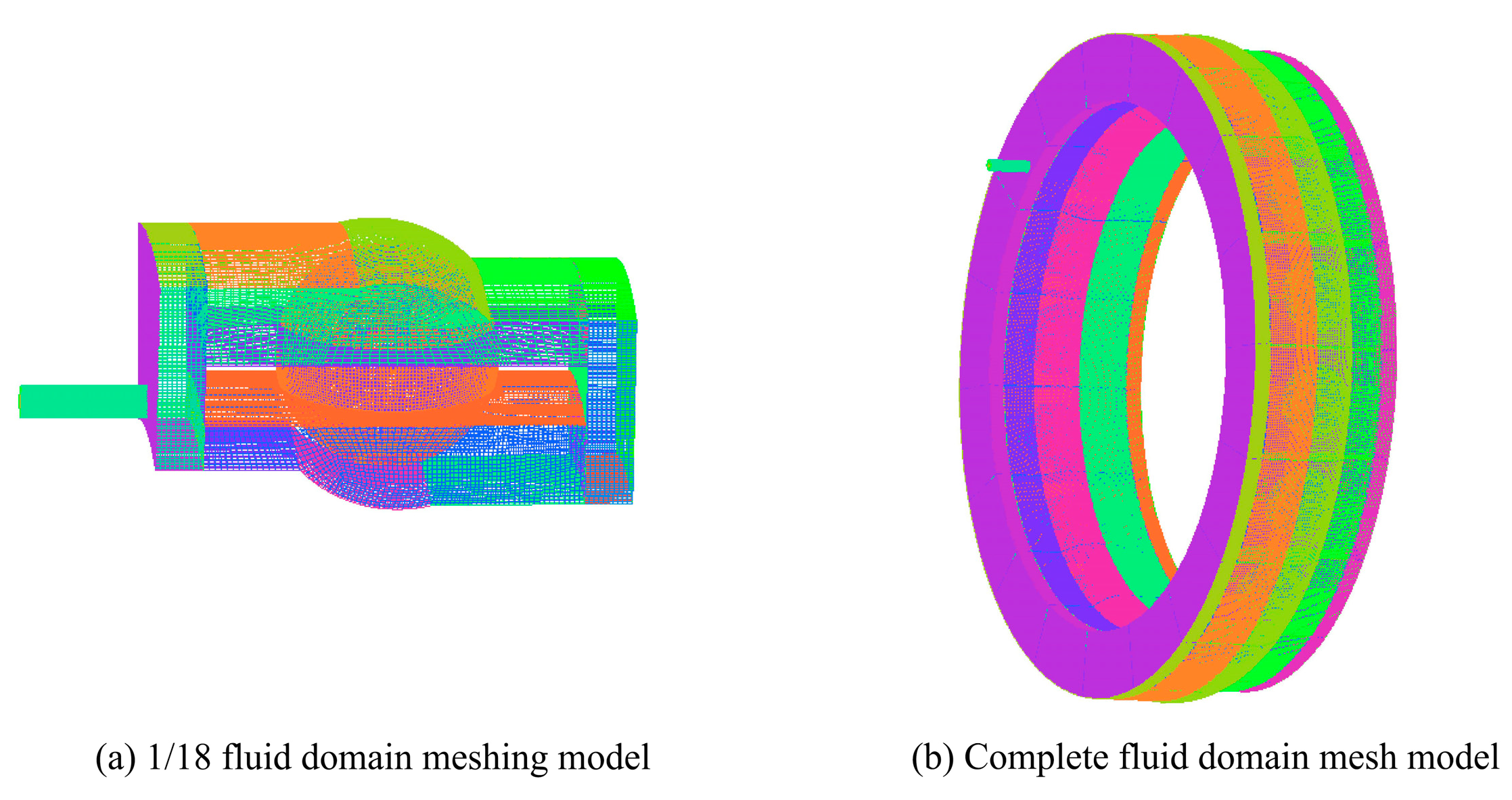
2.1. Geometric Model and Meshing

In this study, a 7008C angular contact ball bearing was selected to establish a bearing fluid domain model and analyze the distribution of fluid in the bearing chamber accurately. The structural parameters are shown in Table 1.
A fluid domain model of a bearing with an oil inlet and pressure inlet was established. The whole model was divided into the nozzle part and the bearing chamber part. The bearing fluid domain structure is shown in Figure 1. The periodic mesh in ICEM CFD was used to divide the fluid domain of 1/18, and then the complete model was obtained by connecting the interface. The meshing model is shown in Figure 2.

2.2. Boundary Conditions and Solution Method Settings

According to the running state of the bearing, the outer ring was set as a non-slip wall. The inner ring and the ball were set as moving walls. For the characteristics of the elastohydrodynamic oil film, the elastohydrodynamic oil film was regarded as a medium that could effectively transfer the force between the rolling element and the inner and outer rings, with the motion of the components in the rolling bearing being simplified to pure rolling. The parameters of each component were determined according to Formulas (1) and (2) [30], as shown in Table 2.
n c = 1 2 [ ( n e + n i ) + ( n e n i ) D b D m cos α ]
n b = 1 2 [ D m D b D b D m cos 2 α ] ( n e n i )
where n c and n b are the revolution and rotation speed of the rolling element; n i and n e are the rotational speed of the inner and outer rings of the bearing; α is the contact angle; D m is the diameter of the bearing pitch circle; and D b is the diameter of the rolling element.
The simulation environment was based on Fluent 2022R1. The multiphase flow was simulated using the VOF (volume-of-fluid) model. Due to the factors that rolling bearings are subjected to during actual operation, such as pressure differences, bubbles are produced inside the fluid. The oil–air two-phase flow of the bearings can better reflect the actual working conditions of the bearings. The VOF model is based on the concept of volume fraction, which divides the fluid domain into regions with different phases and simulates the behavior of multiphase flow by tracking the movement and deformation of the phase interface. During the high-speed operation of the bearing, the two-phase flow of the internal oil and air can be regarded as two incompatible fluid media. Therefore, the simulation of the fluid inside the bearing can be completed by the VOF model. Due to the disturbance caused by the rolling elements, the fluid of each phase is in a turbulent flow state. Considering the rotation and swirling flow, the fluid domain of the bearing chamber adopted the RNG k-ε model. Since the solution of the flow field model was the final stable result, the volume discretization scheme was set as the implicit volume force. The air phase was set as the compressible main phase. The oil phase was set as the incompressible secondary phase. VG68 lubricating oil, comprising mainly polyalkylene glycol (PAG), was chosen. The corresponding fluid parameters are shown in Table 3. The initialized bearing chamber oil was set to zero, and the pressure phase was set using the PRESTO format. The parameters of each fluid domain change with time; thus, the calculation model was solved by PISO, and the time was set as transient.

3. Simulation Results and Analysis

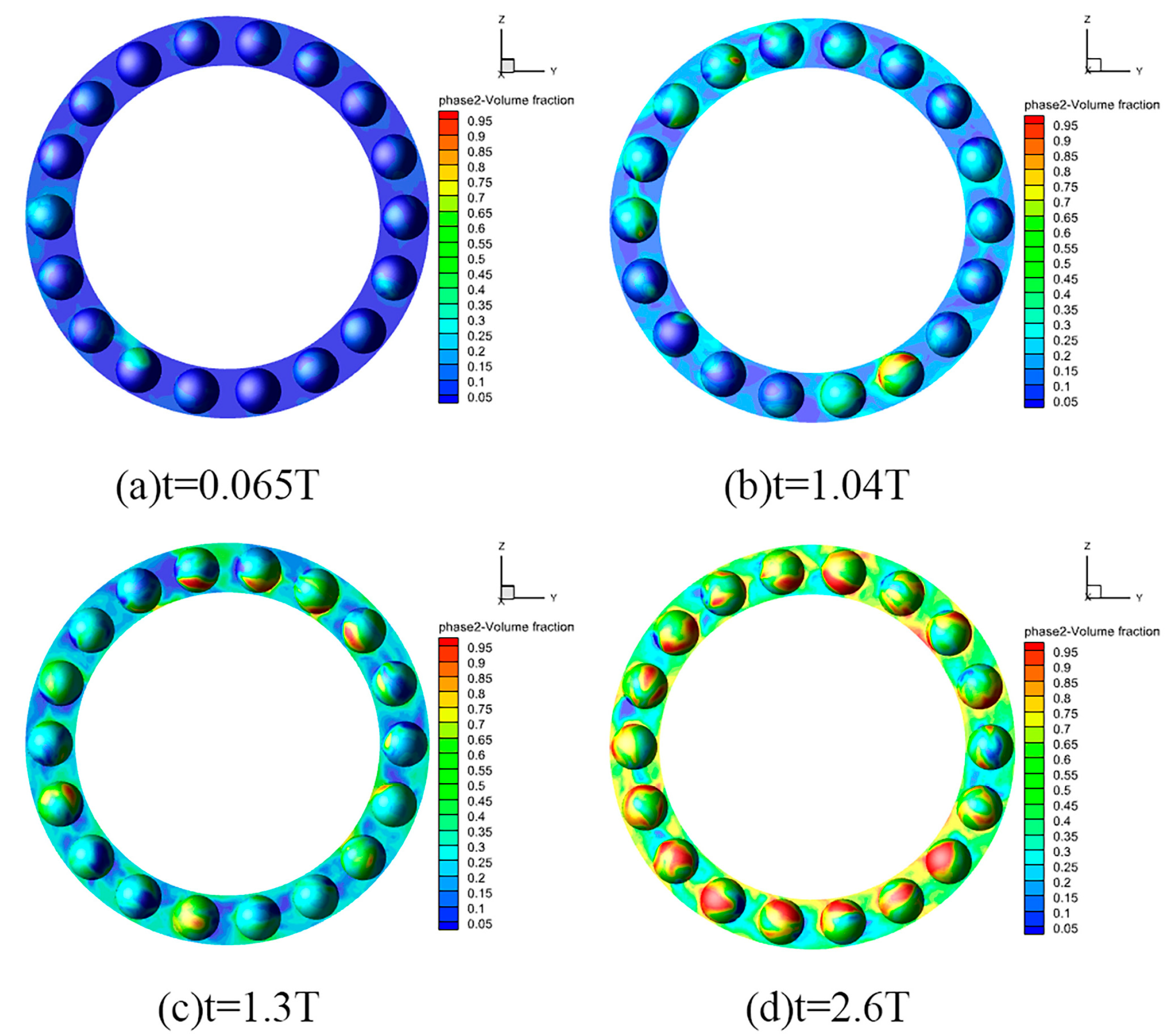
3.1. Oil Diffusion Process

Taking a rotational speed of 800 r/min as an example, Figure 3 shows the oil-phase distribution of the lubricating oil on the surface of the rolling element when bearing rolling commenced. The simulation analysis shows that the calculation time was 2.6 T (T represents the time when the bearing rotated in a circle; T is 0.075 s). The bearing was initially filled with air, and the proportion of the oil phase was zero. At t = 0.065 T, a small amount of oil was attached to the surface of the rolling element, and the distribution of the lubricating oil was not uniform. When t = 1.04 T, the lubricating oil adhered to a thin film on the surface of the rolling element as the bearing continued to run. When t = 1.3 T and t = 2.6 T, the oil diffused with the help of compressed air. The surface of each rolling element had the adhesion of oil. The lubricant was not uniformly distributed in the chamber when the bearing was started. The part near the nozzle could be directly sprayed and covered, enhancing the lubrication. Lubrication away from the nozzle may be insufficient.

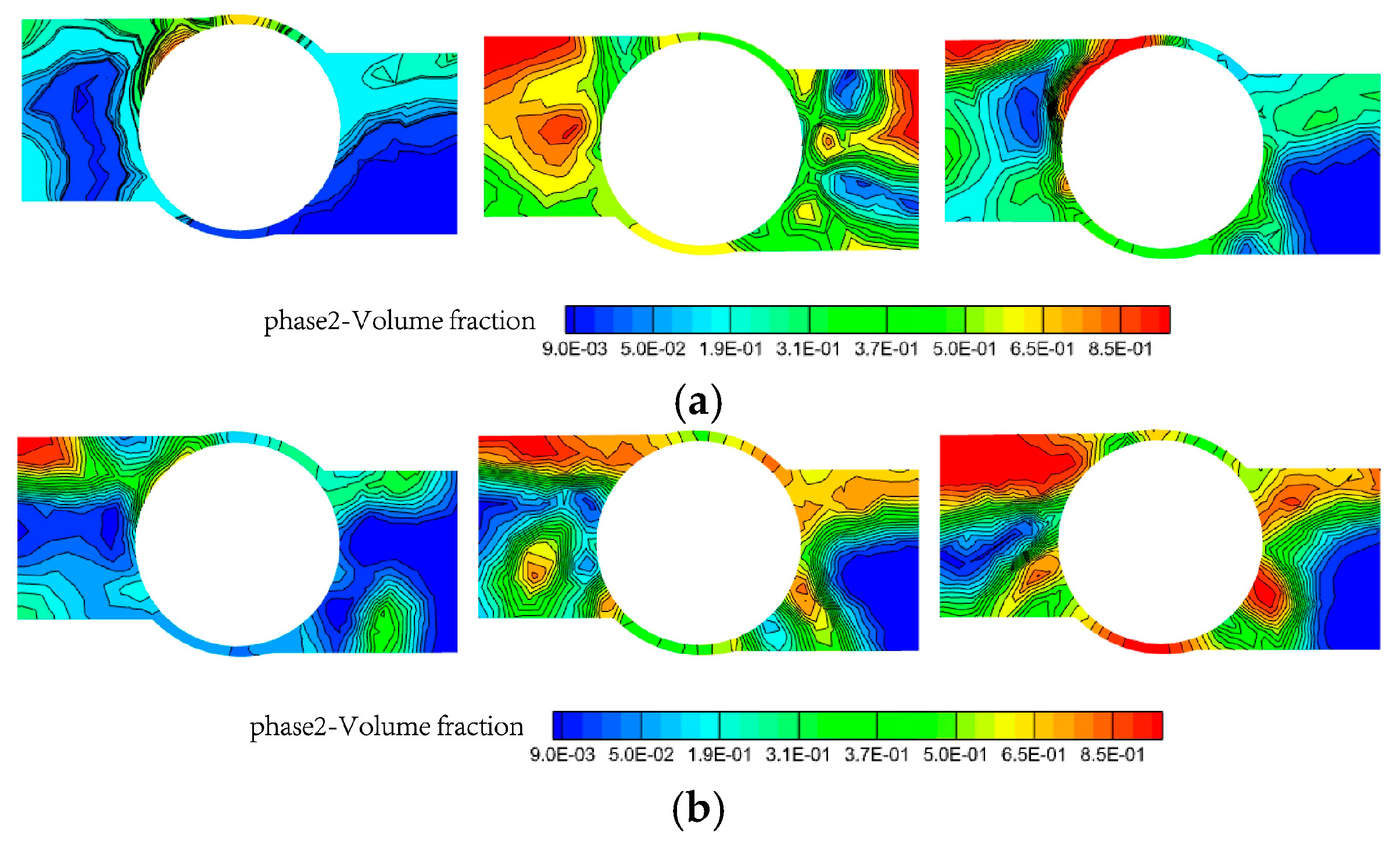
3.2. Phase Interface Diagram Analysis

Diagrams of the oil–air two-phase interface in the bearing chamber at different oil inlet speeds are shown in Figure 4.
This figure demonstrates that an increase in the oil inlet speed resulted in an increase in the oil supply. Meanwhile, a more uniform trend was exhibited by the distribution of the oil film in the bearing chamber, and the film thickness also increased. Due to the fact that the oil supply was insufficient when the oil inlet speed was slow, the oil film was only concentrated in some areas of the bearing, resulting in insufficient lubrication in other areas. Then, more lubricating oil could be distributed evenly throughout the bearing chamber with an increase in the oil inlet speed.

3.3. Effects of Rotational Speed and Oil Inlet Speed on Oil Film State

The various distributions of the oil phase within the bearing chamber at different rotational speeds when the oil inlet speed was maintained at 6 m/s are illustrated in Figure 5a. The rotational speed was 800 r/min, and the oil-phase distribution of the bearing chamber at different oil inlet speeds is shown in Figure 5b. Figure 5a shows that when the rotational speed was low, the oil film near the inner and outer ring channels and the rolling element was thin and nonuniformly distributed, and the lubrication of the inner ring was poor. As the speed increased, the thickness of the oil film gradually increased. The maximum oil film thickness was attained at a rotational speed of 1000 r/min. This is attributed to the fact that as the rotational speed of the inner ring increases, the increase in the velocity of the fluid flow generates sufficient pressure to support the load. When relative motion occurs in the inner ring, the outer ring, and the rolling elements of the rolling bearing, the lubricating oil generates dynamic pressure due to its viscosity and this relative motion. With the enhancement of the hydrodynamic effect, the thickness of the oil film also increases. The airflow vortex near the rolling element is too high when the rotational speed continues to increase. Airflow vortices can lead to a reduction in the local pressure and velocity disorder. This increases the instability of the flow and then interferes with the formation and maintenance of the oil film as the flow of the lubricating oil is impeded. At the same time, the viscosity of the lubricating oil is closely related to temperature. The high temperature caused by the increase in the rotational speed also reduces the viscosity of the lubricating oil. A viscosity that is too low has an influence on the thickness of the oil film and the lubrication performance. As Figure 5b shows, there was an insufficient amount of lubricating oil in the bearing chamber at a low oil inlet speed. The oil film produced during the two-phase flow was thin and incompletely distributed in an oil-starved state. The lubrication was insufficient and, therefore, not conducive to the normal operation of the bearing. With an increase in the oil inlet speed, the oil-phase volume fraction in the bearing chamber increased, the thickness of the lubricating oil film increased, and the distribution became more uniform.

4. Study on Lubrication Characteristics of Textured Rolling Bearing

To improve the uneven distribution of lubricating oil in rolling bearings, increase the thickness of the oil film, and enhance maintenance, surface texture technology was introduced to establish a bearing model with a textured inner ring. This was in order to analyze the lubrication performance of the textured bearings.

4.1. Simplified Model and Meshing

First, the surface texture on the inner ring of the bearing was prepared. The distance between the two pits was 750 μm, the depth of the pit was 30 μm, the diameter of the circular pit was 120 μm, and the angle between the two pits was 10°. To facilitate the analysis and calculation, the influence of the cage and bearing fillets on the lubrication performance was ignored. The 1/18 model of the bearing was meshed and calculated. Due to the bearing model being only 1/18, the mesh division provided by the finite element software was used directly. The solid model and fluid domain model of the textured bearing are shown in Figure 6 and Figure 7, respectively.

4.2. Effect of Surface Texture on Bearing Oil-Phase Distribution

As illustrated in Figure 8, at a rotational speed of 800 r/min, there was a difference in the oil-phase distribution between the conventional bearing and the bearing with texture on the inner raceway. Due to the friction between the air and the surface of the rotating inner and outer rings, the air curtain effect and centrifugal force were produced in the untextured bearing. These factors made it difficult for the lubricating oil to reach the surface of the rolling element directly. Consequently, the outer ring contained a greater quantity of lubricating oil, whilst the inner ring contained a comparatively smaller amount. However, by texturing the inner raceway of rolling bearings, the lubricating oil could be dispersed more evenly throughout all parts of the bearing chamber. Compared with the untextured bearings, the content of lubricating oil near the contact area of the textured inner ring was significantly increased. This may be due to the fact that the presence of textures leads to variations in the fluid pressure and flow velocity. The resulting differences in the fluid pressure and velocity reinforce the hydrodynamic effect. Meanwhile, the arrangement of textures can guide the flow of the lubricating oil, thereby enabling a more uniform distribution of the lubricating oil. This indicates that texturing treatment can optimize the distribution of the lubricating oil and enhance the lubrication effect on the inner ring.

4.3. Effect of Texture Area Occupancy Ratio on Lubrication Performance

Figure 9 shows the oil-phase volume fraction of the bearing chamber under different texture area occupancy ratios. The results show that the oil-phase volume fraction of the bearing chamber on the textured surface was greater than that on the smooth surface. This was caused by the lubricating oil passing through the micro-pits under the drive of the rolling elements and the micro-pits changing the distance inside the bearing. Due to the viscosity of the fluid, under specific geometric shapes, the speed distribution of the fluid changed, resulting in the generation of a pressure difference. The change in distance enhanced the hydrodynamic pressure effect. Therefore, the oil-phase volume fraction increased under the influence of the texture. However, as the area occupancy ratio of the texture increased, the oil-phase volume fraction decreased. Due to a reduction in the spacing between the micro-pits, the fluid flow was restricted, resulting in a decrease in the dynamic pressure effects and oil-phase volume fraction. When designing the surface texture, it is essential to ensure that increasing the texture area occupancy ratio does not excessively reduce the fluid dynamic pressure effect; meanwhile, it is important to consider its impact on the storage capacity of the lubricating oil, thereby maintaining the good lubrication performance of the bearing.

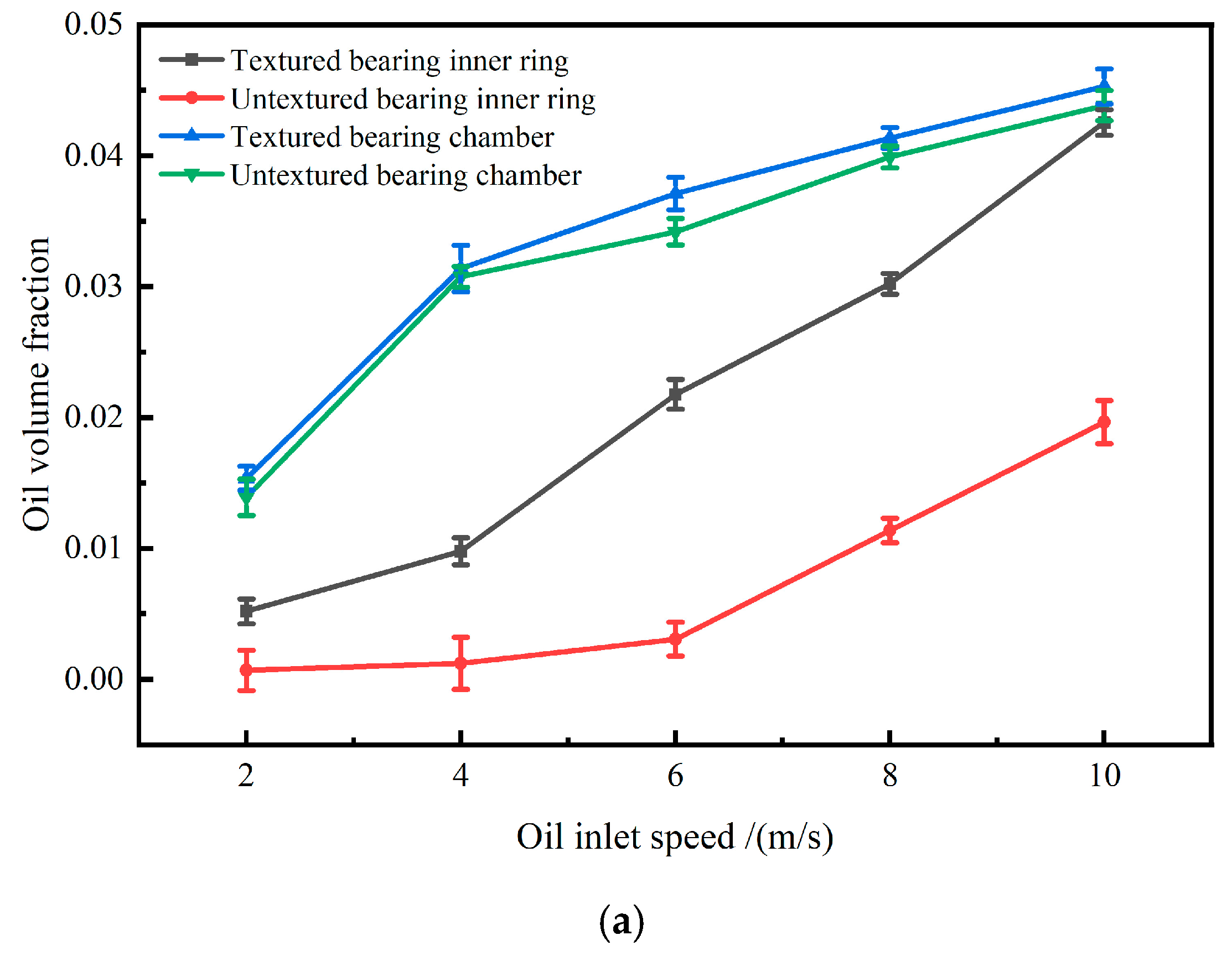
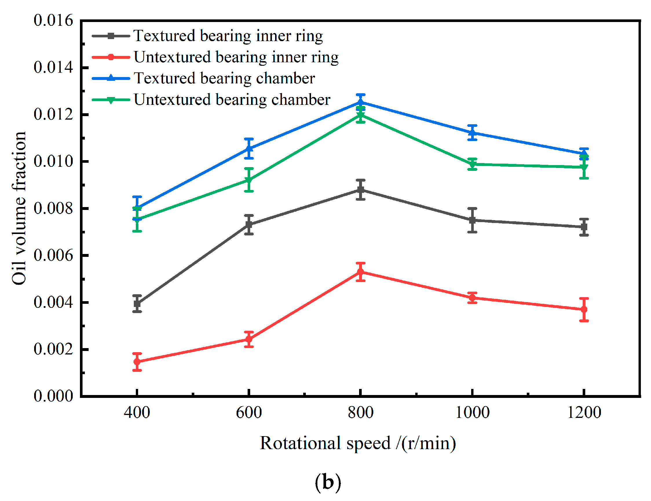
4.4. Effect of Oil Inlet Speed and Rotational Speed on Lubrication Performance

Figure 10a illustrates the influence of different oil inlet speeds on the volume fraction of the bearing oil phase at a fixed rotational speed of 800 r/min. It is shown that an increase in the oil inlet speed increased the oil-phase volume fraction in the inner ring and bearing chamber. The effect of texture on the oil-phase volume fraction in the inner ring was more obvious than that in the bearing chamber. This is because the textured micro-pits arranged in the inner ring can store more lubricating oil and, thus, provide continuous secondary lubrication. This situation was more obvious when the oil inlet speed was higher. Compared with textured bearings, untextured bearings have a poorer oil storage performance in the inner ring; as the supply of oil increases, the difference in the content of the oil increases. Figure 10b shows the effect of the oil-phase volume fraction when the oil inlet speed was fixed at 2 m/s and the rotational speed was changed. The oil content first increased and then decreased. However, the oil content in the textured bearing areas was always higher than that in the untextured bearing areas, whether it was in the inner ring of the bearing or the bearing chamber. This was because as the rotational speed gradually increased, the lubricating oil originally stored in the texture began to flow out from the inside of the texture due to the synergy between the hydrodynamic effect, centrifugal force, and other multiple factors. This caused the oil-phase volume fraction to increase. However, when the rotational speed was too high, due to the decrease in the viscosity of the lubricating oil, the lubricating oil decreased. This led to a reduction in the oil-phase volume fraction. Compared with untextured bearings, textured bearings can provide local support and secondary lubrication to the oil film, ensuring that the lubricating oil is stably distributed during the operation of the bearing and preventing the premature rupture of the oil film. In addition, textured bearings can also effectively guide the flow of the lubricating oil. Therefore, the oil-phase volume fraction of the textured inner ring and bearing chamber is always higher than that of the untextured bearings. This indicates that texture significantly improves the friction characteristics of bearings.

5. Frictional Experiment

From the above research, it is evident that surface textures can optimize the mechanisms and characteristics of lubrication and improve the friction and wear conditions in the contact area. In order to further explore the mechanism of this effect, textures were designed and processed on a simplified raceway contact surface. Moreover, the friction performance of point contact friction pairs was assessed.

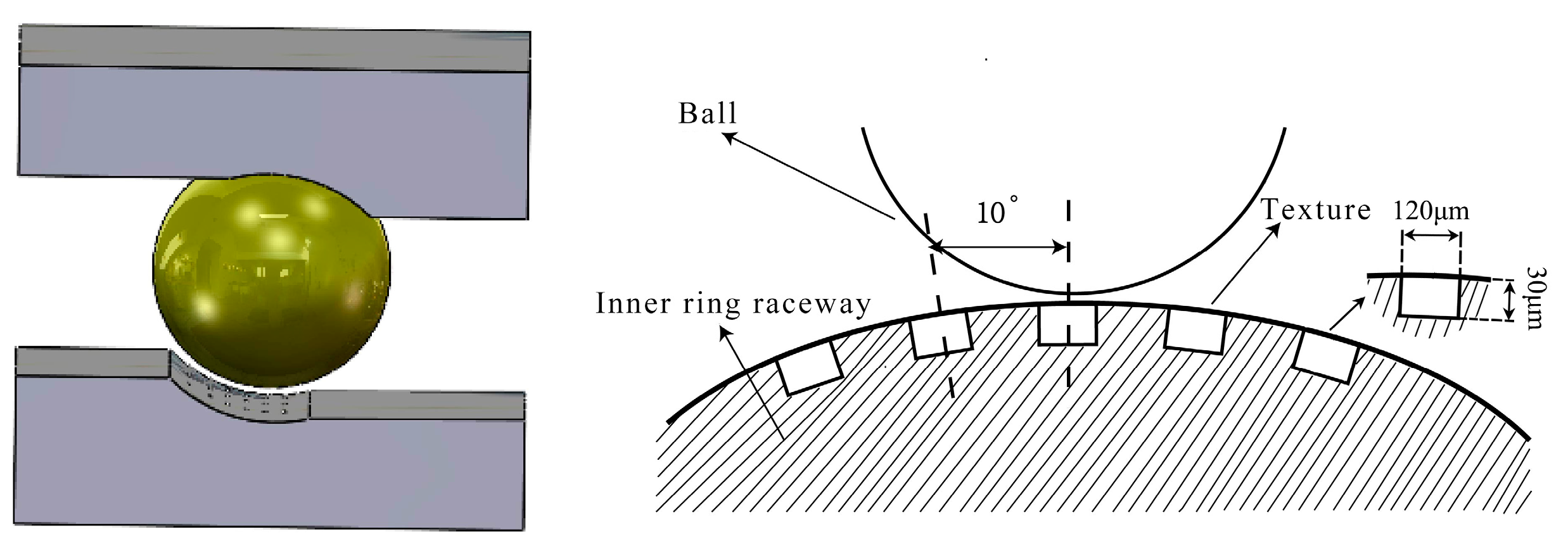
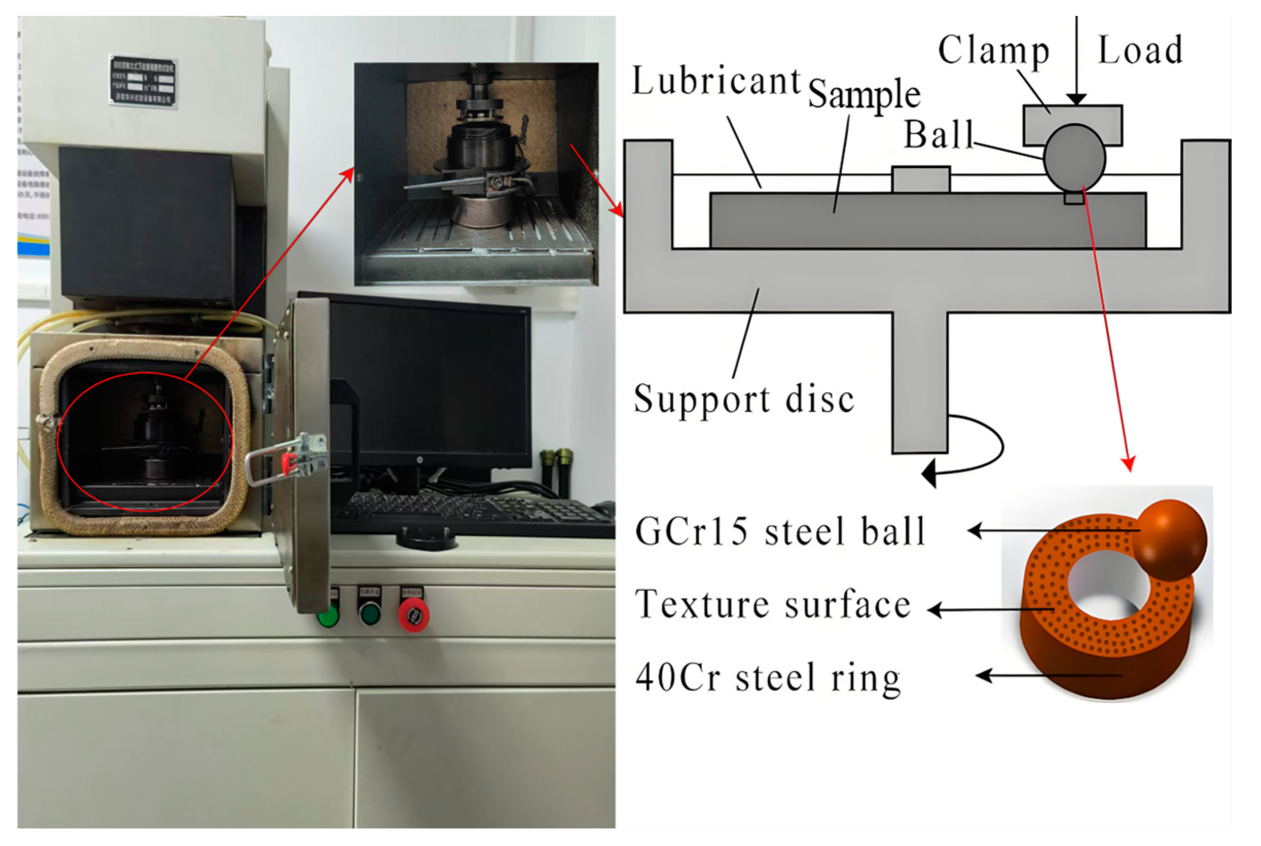
5.1. Design and Processing of Textured Specimens

Ignoring the curvature of the inner ring raceway in rolling bearings, the raceway contact surface was simplified to a rough plane. The 40 Cr steel ring with good mechanical properties and wear resistance was selected as the specimen material. According to the simulation model presented in the previous section, micro-pit textures were designed. The pit diameter was 120 μm, and the area occupancy ratios were 6%, 12%, and 18%, respectively. Table 4 shows the detailed parameters and numbering of the textured specimens.
Textured specimens with different area occupancy ratios were manufactured using a laser-processing machine, as shown in Figure 11. The laser-processing machine consisted of a laser lens, a laser beam, and a working platform and was connected to a computer. The device applied a continuous laser beam with a high power density to the processed material via an optical element. Once the energy on the surface of the material in the irradiation area had been absorbed, it was focused onto a small spot using a higher temperature. Then, textured micro-pits were formed.
While ensuring that the other parameters remained unchanged, four laser-processing parameters, namely, the laser power, scanning speed, pulse frequency, and scanning time, were set to control the spacing and depth-to-diameter ratio of the texture. The optimal laser-marking parameters are shown in Table 5.
Once the texture had been processed, the specimens were polished with metallographic sandpaper to remove the debris left on the surface of the texture after laser marking. Then, the effect of polishing was observed using a metallographic microscope and a two-dimensional profilometer. Finally, the specimens were placed in an acetone solution for ultrasonic cleaning. The textured specimens with different area occupancy ratios were then tested, as shown in Figure 12.

5.2. Experimental Method

The MMW-1000 friction and wear-testing machine was used for the experimental study of point contact friction pairs. A ball-on-disc friction pair composed of upper and lower specimens was employed, as shown in Figure 13. The upper specimen was a rotating GCr15 (d = 12.5 mm) steel ball, and the lower specimen was a fixed 40Cr ring specimen. The outer diameter of the ring specimen was 28.36 mm, the inner diameter was 13.84 mm, the environmental temperature was 22 °C, and the humidity was 36%. The experiment used standard Mobil 10W-40 lubricating oil with a density of 840 kg/m3 and a viscosity of 6.95 × 10⁻³ mm2/s at 40 °C.

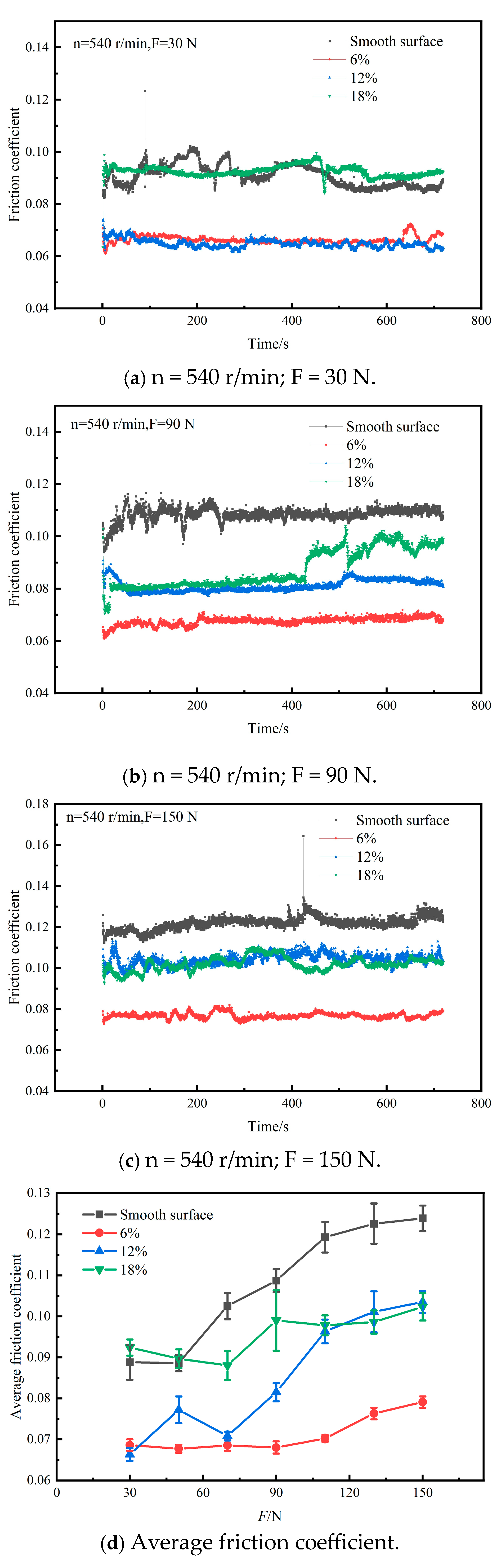
5.3. Effect of Load on Friction Characteristics of Textured Surface

When multiple experiments with different durations were conducted, it was found that the friction coefficients of some specimens changed significantly after 400 s. A shorter experimental duration failed to effectively show the friction and wear properties of the specimens in the stable stage. If the experimental duration was extended and the influence of various factors, such as equipment limitations, on the test results were excluded, the curve was expected to maintain the same trend for a long period of time. Considering the accuracy and efficiency of the experiment, 720 s was chosen as the experimental duration. The friction coefficient curves obtained at a rotational speed of 540 r/min and loads of 30 N, 90 N, and 150 N, respectively, are shown in Figure 14. This figure shows that the friction coefficient of each surface increased with the change in load. However, the friction coefficients of the textured surfaces were generally smaller than those of the smooth surface. As demonstrated in Section 4.2, the simulation analysis results indicate that the presence of texture leads to an increase in the oil-phase volume fraction of textured surfaces. It appears that sufficient lubricating oil can ensure that the lubrication performance of the textured surfaces remains good, thus reducing the friction coefficient. From the figure, it is clear that the average friction coefficient of the smooth surface was not its lowest under a low load. This may be due to the fact that the friction coefficient was greatly affected by the roughness under a low load. The friction coefficient of the textured surface progressively became lower than that of the smooth surface as the load applied increased. This is consistent with the oil storage performance of micro-pits and indicates that the surface texture can significantly improve the performance of friction pairs under high load.

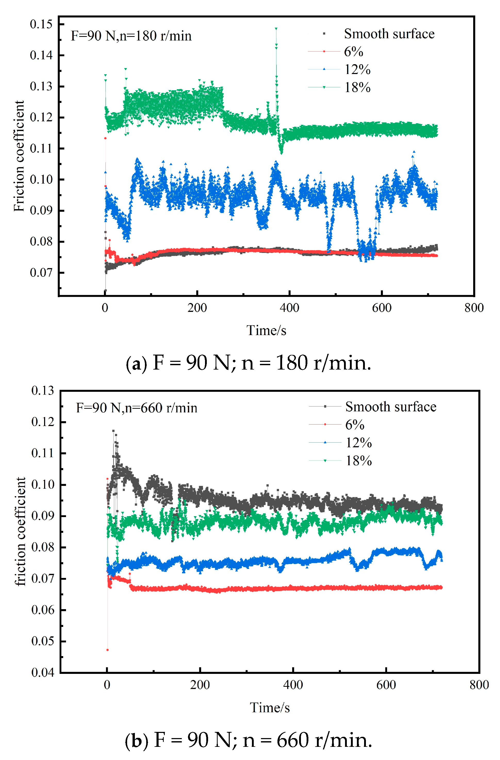
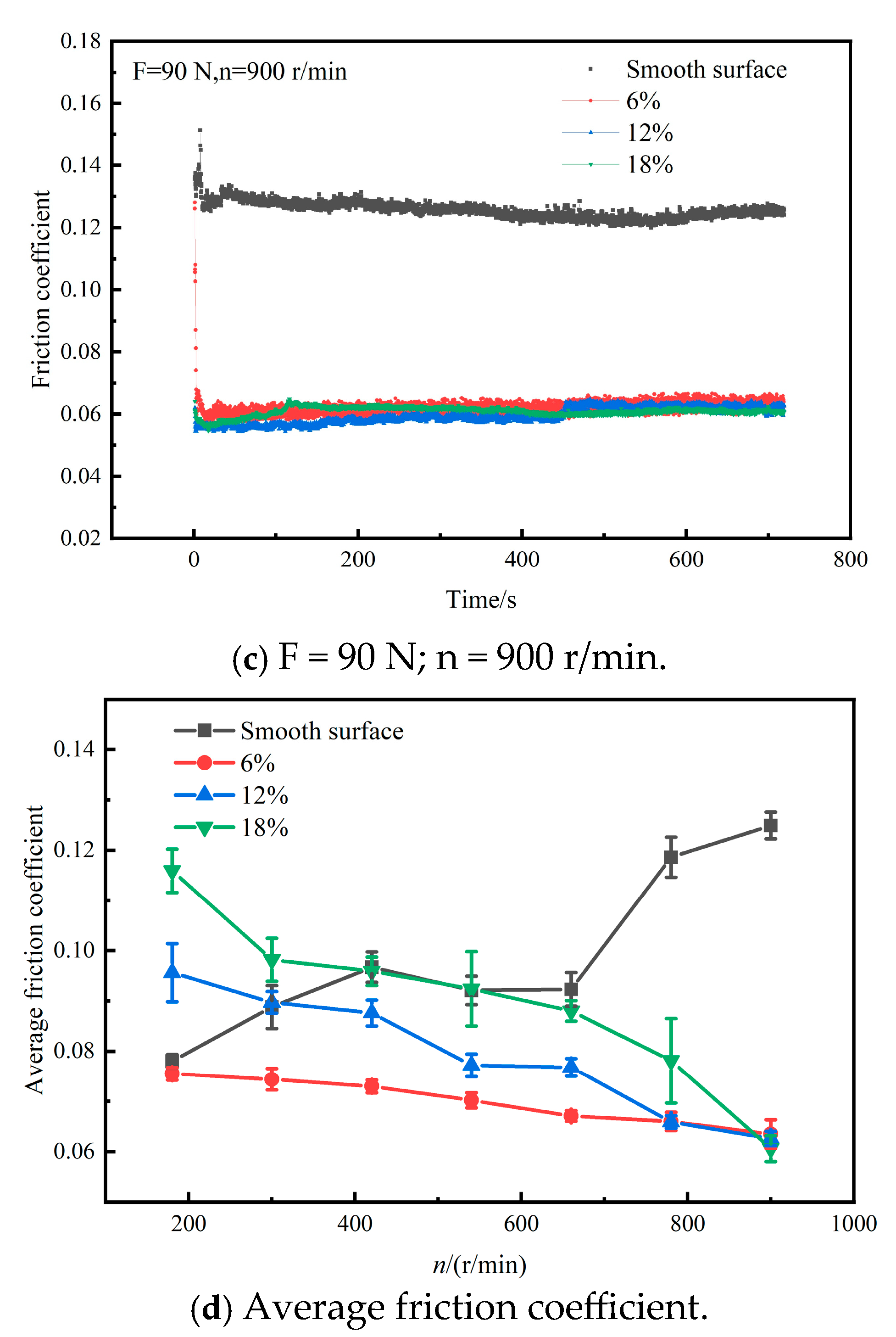
5.4. Effect of Rotational Speed on Friction Characteristics of Textured Surface

The friction coefficient curves at a load of 90 N and rotational speeds of 180 r/min, 660 r/min, and 900 r/min, respectively, are shown in Figure 15. It can be observed that the larger the area occupancy ratio at a low rotational speed, the worse the anti-friction effect on the textured surface. This is because at low rotational speeds, when the friction pair enters the elastohydrodynamic contact zone, the surface roughness with a larger area occupancy ratio increases; meanwhile, the contact area decreases, resulting in a decrease in the oil film′s bearing capacity and the inability to form a stable lubricating film. The friction coefficient of the textured surface was negatively correlated with the rotational speed as the rotational speed increased, while the smooth surface showed the opposite trend. In accordance with the simulation results in Section 4.4, as the rotational speed increased, the surface texture underwent secondary lubrication. This increased the oil-phase volume fraction in the contact area, which enhanced the dynamic pressure effect on the contact surface, making the distribution of the oil phase more uniform. Meanwhile, as the experiment progressed, the lubricant on the contact pair of the smooth surface gradually evaporated, and dry friction may have occurred. By analyzing the test results for the four surfaces, it is clear that the surface texture can effectively improve the lubrication performance of bearings and reduce their friction coefficient at a high rotational speed.

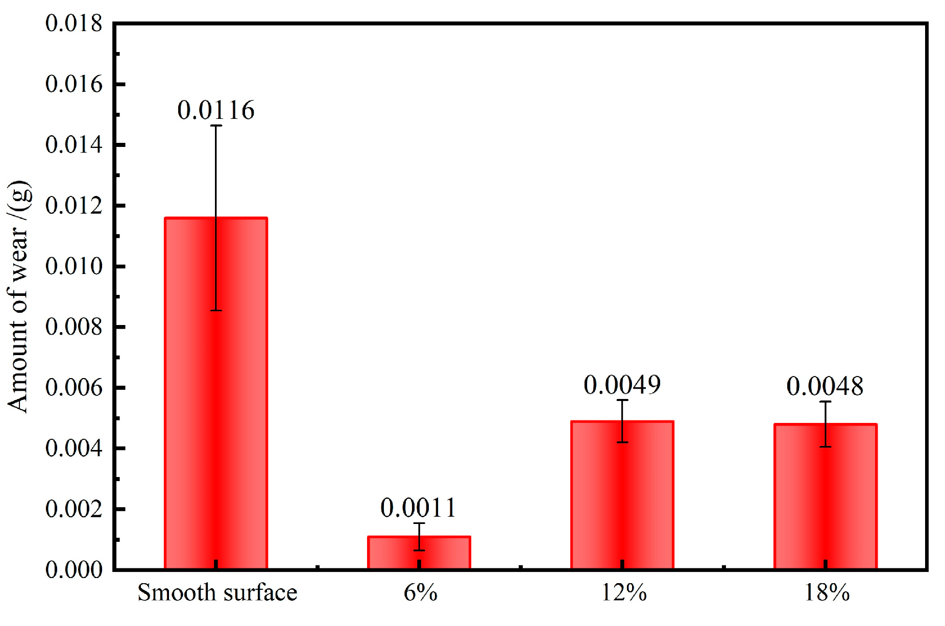
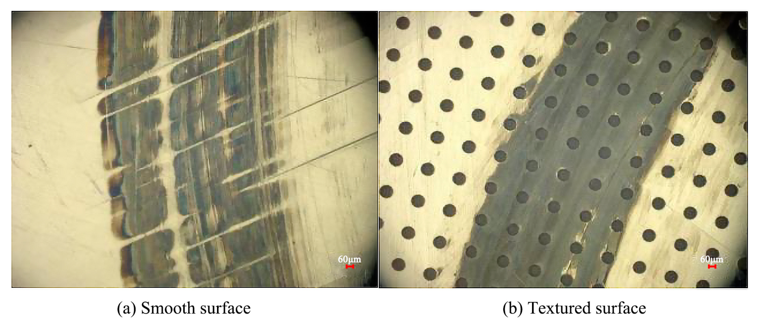
5.5. Analysis of Surface Wear and Wear Traces

Figure 16 shows the wear on each specimen after the completion of the experimental process. It can be seen that the textured surface performed outstandingly in terms of wear. In accordance with the simulation results, the textured surface with a 6% area occupancy ratio had the best lubrication effect. The function of secondary lubrication led to an increase in the oil-phase volume fraction, which improved the lubrication performance and reduced the material wear. The smooth surface quality was reduced by 0.0116 g, the textured surfaces with occupancy ratios of 12% and 18% were reduced by 0.0049 g and 0.0048 g, and the textured surface with an occupancy ratio of 6% was reduced by 0.0011 g.
As shown in Figure 17, a comparison of the wear on the smooth surface and the textured surface is presented. On the smooth surface, there are relatively obvious abrasion marks, and the wear traces are distributed in a rather scattered manner. In contrast, the wear traces on the textured surface are more concentrated. This may be because on the smooth surface, wear debris was generated after long-term friction, and the oil film was damaged, thus forming abrasion marks. However, on the textured surface, the pits contributed to the collection of wear debris and enhanced lubrication. As a result, the wear traces were more concentrated, and there were no obvious abrasion marks.

6. Conclusions

In this study, the changes in the oil–air two-phase flow of an angular contact ball bearing were analyzed. The positive effect of the textured surface topography on the lubrication performance of the bearing under different working conditions was studied. The frictional experiment was carried out on a simplified raceway. It was verified that a textured surface can effectively reduce the friction coefficient and wear under a high load and high rotational speed. The following conclusions are drawn:
  • From the two-phase flow model of the untextured bearing, it can be seen that the oil film of the angular contact ball bearing was nonuniformly distributed during operation and that the lubrication conditions were poor in some areas. Under appropriate rotational speeds and oil inlet speeds, the oil-phase distribution in the bearing chamber became gradually uniform, and the lubrication state of the bearing became relatively good. However, some areas continued to experience poor lubrication.
  • From the CFD model of the textured bearing, it is clear that compared with the untextured bearing, the textured bearing exhibited a relatively good lubricating performance under the same working conditions and could effectively overcome the poor lubrication of the bearings. The influence of texture on the oil-phase volume in the inner ring was greater than that on the bearing chamber. Among the three different texture area occupancy ratios, the oil-phase volume fraction in the bearing chamber was the highest when the texture area occupancy ratio was 6%. However, the oil-phase volume fraction in the bearing chamber of all textured bearings was higher than that in the untextured bearing.
  • As demonstrated by the experimental findings, the textured surface was effective in reducing friction and enhancing wear resistance. Among the surfaces, the textured surface with a 6% area occupancy ratio showed the best anti-friction and anti-wear performance, and the data are in line with the simulation results. Due to the increase in the oil-phase volume fraction on the textured surface, the thickness of the oil film increased. The lubrication effect of the specimens was improved, and the friction coefficient was, consequently, reduced. The test results for three textured surfaces show that a textured surface is more conducive to the improvement of tribological properties under a high load and high rotational speed.

Author Contributions

Conceptualization, Z.L.; methodology, Q.Z. and X.Z.; software, Z.L. and S.Y.; validation, S.Y.; formal analysis, S.Y.; investigation, Q.Z. and X.Z.; resources, H.Z.; writing—original draft preparation, S.Y.; writing—review and editing, Z.L.; visualization, Q.Z. and X.Z.; supervision, Z.L.; project administration, H.Z.; funding acquisition, H.Z. All authors have read and agreed to the published version of the manuscript.

Funding

This research was funded by the National Natural Science Foundation of China, grant number 52475117.

Data Availability Statement

The original contributions presented in this study are included in this article.

Conflicts of Interest

The authors declare no conflicts of interest.

References

  1. Liu, Y.; Chen, Z.; Zhai, W.; Lei, Y. Investigation on skidding behavior of a lubricated rolling bearing with fluid-solid-heat coupling effect. Mech. Syst. Signal Process. 2024, 206, 110922. [Google Scholar] [CrossRef]
  2. Qin, Y.; Li, C.; Wu, X.; Wang, Y.; Chen, H. Multiple-degree-of-freedom dynamic model of rolling bearing with a localized surface defect. Mech. Mach. Theory 2020, 154, 104047. [Google Scholar] [CrossRef]
  3. Meng, F.; Zheng, Y.; Liu, Y.; Gong, J.; Wang, B. Multi-ellipsoid contact elastohydrodynamic lubrication performance for deep groove ball bearing. Tribol. Int. 2020, 150, 106367. [Google Scholar] [CrossRef]
  4. Yan, K.; Zhang, J.; Hong, J.; Wang, Y.; Zhu, Y. Structural optimization of lubrication device for high speed angular contact ball bearing based on internal fluid flow analysis. Int. J. Heat Mass Transfer. 2016, 95, 540–550. [Google Scholar] [CrossRef]
  5. Yao, Q.; Dai, L.; Tang, J.; Wu, H.; Liu, T. High-speed rolling bearing lubrication reliability analysis based on probability box model. Probab. Eng. Mech. 2024, 76, 103612. [Google Scholar] [CrossRef]
  6. Kim, S.; Seo, Y.H.; Park, J. Transformer-based novel framework for remaining useful life prediction of lubricant in operational rolling bearings. Reliab. Eng. Syst. Saf. 2024, 251, 110377. [Google Scholar] [CrossRef]
  7. Wang, Y.; Wang, W.; Li, Y.; Zhao, Z. Lubrication and Thermal Failure Mechanism Analysis in High-Speed Angular Contact Ball Bearing. ASME J. Tribol. 2018, 140, 031503. [Google Scholar]
  8. Liu, J.; Ni, H.; Xu, Z.; Pan, G. A simulation analysis for lubricating characteristics of an oil-jet lubricated ball bearing. Simul. Model. Pract. Theory 2021, 113, 102371. [Google Scholar] [CrossRef]
  9. Liu, C.; Li, W.; Guo, F.; Wong, P.; Li, X. Effect of Oil Dispersion on Lubricating Film Thickness Generation under Oil Droplet Supply Conditions. Lubricants 2023, 11, 512. [Google Scholar] [CrossRef]
  10. Yu, X.; Sun, Y.; Wu, S. A complete deterministic model of point contact mixed lubrication coupling dual-mode effects of surface fractal characteristics. Int. J. Non. Linear Mech. 2024, 161, 104669. [Google Scholar] [CrossRef]
  11. Zhang, X.; Glovnea, R. Grease film thickness measurement in rolling bearing contacts. Proc. Inst. Mech. Eng. Part J J. Eng. Tribol. 2020, 235, 1430–1439. [Google Scholar] [CrossRef]
  12. Wen, B.; Li, Y.; Wang, M.; Yang, Y. Measurement for Lubricant Distribution in an Angular Contact Ball Bearing and Its Influence Investigation. Lubricants 2023, 11, 63. [Google Scholar] [CrossRef]
  13. Liang, H.; Zhang, Y.; Wang, W. Influence of the cage on the migration and distribution of lubricating oil inside a ball bearing. Friction 2022, 10, 1035–1045. [Google Scholar]
  14. Su, B.; Zou, X.; Wang, Z.; Huang, L. Numerical analysis of lubrication properties on a bio-inspired parabolic textured surface. Meccanica 2024, 59, 987–1000. [Google Scholar] [CrossRef]
  15. Peta, K. Multiscale Wettability of Microtextured Irregular Surfaces. Materials 2024, 17, 5716. [Google Scholar] [CrossRef] [PubMed]
  16. Fang, J.; Liu, X.; Wang, T.; Song, Z. Micro Lubrication and Heat Transfer in Wedge-Shaped Channel Slider with Convex Surface Texture Based on Lattice Boltzmann Method. Nanomaterials 2024, 14, 295. [Google Scholar] [CrossRef]
  17. Wang, W.; He, Y.; Li, Y.; Wei, B.; Hu, Y.; Luo, J. Investigation on inner flow field characteristics of groove textures in fully lubricated thrust bearings. Ind. Lubr. Tribol. 2018, 70, 754–763. [Google Scholar]
  18. Adeyemi, K.; Sun, B.; Xue, W.; Liu, W.; Cao, Y. Friction and Wear Characteristics Modification via Laser Surface Textured Grooves. Surf. Eng. 2020, 37, 658–668. [Google Scholar] [CrossRef]
  19. Bonse, J.; Kirner, S.V.; Griepentrog, M.; Spaltmann, D.; Krüger, J. Femtosecond Laser Texturing of Surfaces for Tribological Applications. Materials 2018, 11, 801. [Google Scholar] [CrossRef]
  20. Zhao, X.; Zhang, Y. Analysis of the tribological and dynamic performance of textured bearings under contaminated conditions. Tribol. Int. 2023, 187, 108732. [Google Scholar]
  21. Kango, S.; Sharma, R.K.; Pandey, R.K. Thermal analysis of microtextured journal bearing using non-Newtonian rheology of lubricant and JFO boundary conditions. Tribol. Int. 2014, 69, 19–29. [Google Scholar] [CrossRef]
  22. Zhao, X.; Zhang, Y. Tribological and dynamic performance analysis of rolling bearings with varied surface textures operating under lubricant contamination. Wear 2023, 532–533, 205109. [Google Scholar] [CrossRef]
  23. Sep, J.; Tomczewski, L.; Galda, L.; Dzierwa, A. The study on abrasive wear of grooved journal bearings. Wear 2017, 376–377, 54–62. [Google Scholar] [CrossRef]
  24. Liu, W.; Ni, H.; Wang, P.; Chen, H. Investigation on the tribological performance of micro-dimples textured surface combined with longitudinal or transverse vibration under hydrodynamic lubrication. Int. J. Mech. Sci. 2020, 174, 105474. [Google Scholar] [CrossRef]
  25. Vidyasagar, K.E.C.; Pandey, R.K.; Kalyanasundaram, D. Improvement of Deep Groove Ball Bearing’s Performance Using a Bionic Textured Inner Race. J. Bionic. Eng. 2021, 18, 974–990. [Google Scholar] [CrossRef]
  26. Bhardwaj, V.; Pandey, R.K.; Agarwal, V.K. Experimental exploration for the performance improvement of a thrust ball bearing using circumferential micro-grooved races. Surf. Topogr. Metrol. Prop. 2021, 9, 035017. [Google Scholar] [CrossRef]
  27. Wu, C.; Yang, K.; Ni, J.; Lu, S.; Yao, L.; Li, X. Investigations for vibration and friction torque behaviors of thrust ball bearing with self-driven textured guiding surface. Friction 2023, 11, 894–910. [Google Scholar] [CrossRef]
  28. Gouda, B.; Tandon, N.; Pandey, R.K.; Babu, C.K. Performance improvement of a radial ball bearing using a micro-groove on stationary outer race. Proc. Inst. Mech. Eng. Part C J. Mech. Eng. Sci. 2022, 236, 11521–11536. [Google Scholar] [CrossRef]
  29. Han, K.; Li, J.; Wang, Q.; Chen, W.; Xue, J. Study on oil film pressure distribution and load capacity of textured rolling bearings. Ind. Lubr. Tribol. 2020, 72, 961–967. [Google Scholar] [CrossRef]
  30. Wen, S.; Huang, P.; Tian, Y.; Ma, L. Principles of Tribology, 5th ed.; Tsinghua University Press: Beijing, China, 2018; p. 96. [Google Scholar]
Figure 1. Flow field model of bearing.
Lubricants 13 00041 g001
Figure 2. Fluid domain meshing model.
Lubricants 13 00041 g002
Figure 3. Variation process of oil-phase distribution.
Lubricants 13 00041 g003
Figure 4. Oil–air two-phase interface diagram in 800 r/min bearing chamber (oil inlet speeds: 2 m/s, 4 m/s, and 6 m/s).
Lubricants 13 00041 g004
Figure 5. Oil-phase distribution in bearing chamber at different rotational speeds and oil inlet speeds. (a) Oil-phase distribution at different rotational speeds (800 r/min, 1000 r/min, and 1200 r/min); (b) oil-phase distribution at different oil inlet speeds (2 m/s, 4 m/s, and 6 m/s).
Lubricants 13 00041 g005
Figure 6. Solid model of textured bearing.
Lubricants 13 00041 g006
Figure 7. Fluid domain model of textured bearing.
Lubricants 13 00041 g007
Figure 8. Comparison of oil-phase distribution of fluid domain section.
Lubricants 13 00041 g008
Figure 9. Effect of texture area occupancy ratio on bearing lubrication performance.
Lubricants 13 00041 g009
Figure 10. Effect of bearing oil inlet speed and rotational speed on oil-phase volume fraction. (a) Effect of oil inlet speed on oil-phase volume fraction; (b) effect of rotational speed on oil-phase volume fraction.
Lubricants 13 00041 g010aLubricants 13 00041 g010b
Figure 11. Laser-processing schematic diagram.
Lubricants 13 00041 g011
Figure 12. Textured specimens with different area occupancy ratios.
Lubricants 13 00041 g012
Figure 13. Experimental bench and friction pair.
Lubricants 13 00041 g013
Figure 14. Friction coefficients under different loads.
Lubricants 13 00041 g014
Figure 15. Friction coefficients at different rotational speeds.
Lubricants 13 00041 g015aLubricants 13 00041 g015b
Figure 16. Wear amounts on different surfaces.
Lubricants 13 00041 g016
Figure 17. Comparison of surface wear traces.
Lubricants 13 00041 g017
Table 1. Main structural parameters of angular contact ball bearing.
ParameterValue
Inner diameter40 mm
Outer diameter68 mm
Width15 mm
Ball diameter3.5 mm
Number of balls18
Contact angle15°
Ring materialsGCr15
Ball materialsGCr15
Table 2. Parameters of each component of the bearing.
Inner Ring Speed (r/min)Pitch Diameter (mm)Rolling Element Diameter
(mm)
Contact Angle
(°)
Rolling Element Revolution Speed
(r/min)
Rolling Element Rotation Speed (r/min)
800543.515424−3221
1000543.515518−3774
1200543.515623−4529
Table 3. Oil and air material parameters.
ParametersAirOil
Density ρ (kg/m3)1.225876
Specific heat Cp (J/(kg·K)10131995
Dynamic viscosity η (Pa·s)1.79 × 10−50.0525
Temperature T (K)298.15298.15
Table 4. Specimen parameters and numbering.
Texture ShapeTexture Diameter (d)/μmArea Occupancy Ratio (Sp)/%Numbers (n)Depth (h)/μm
Circular pit120647744
Circular pit1201295494
Circular pit1201814,3234
Table 5. Laser-marking parameters.
EquipmentLaser Power
/W
Pulse Frequency
/kHz
Scanning Speed
/(mm/s)
Scanning Time
Nanosecond laser30202001
Disclaimer/Publisher’s Note: The statements, opinions and data contained in all publications are solely those of the individual author(s) and contributor(s) and not of MDPI and/or the editor(s). MDPI and/or the editor(s) disclaim responsibility for any injury to people or property resulting from any ideas, methods, instructions or products referred to in the content.

