Article

Computational Modeling and Constructal Design Theory Applied to the Geometric Optimization of Thin Steel Plates with Stiffeners Subjected to Uniform Transverse Load

1
Graduate Program in Ocean Engineering, Federal University of Rio Grande–FURG, Rio Grande 96203-900, Brazil
2
Graduate Program in Mechanical Engineering, University of Vale do Rio dos Sinos–UNISINOS, São Leopoldo 93022-750, Brazil
3
Department of Industrial Engineering, University of Bologna–UNIBO, 40165 Bologna, Italy
*
Author to whom correspondence should be addressed.
Metals 2020, 10(2), 220; https://doi.org/10.3390/met10020220
Submission received: 27 December 2019 / Revised: 31 January 2020 / Accepted: 1 February 2020 / Published: 4 February 2020

Abstract

:
Stiffened thin steel plates are structures widely employed in aeronautical, civil, naval, and offshore engineering. Considering a practical application where a transverse uniform load acts on a simply supported stiffened steel plate, an approach associating computational modeling, Constructal Design method, and Exhaustive Search technique was employed aiming to minimize the central deflections of these plates. To do so, a non-stiffened plate was adopted as reference from which all studied stiffened plate’s geometries were originated by the transformation of a certain amount of steel of its thickness into longitudinal and transverse stiffeners. Different values for the stiffeners volume fraction (φ) were analyzed, representing the ratio between the volume of the stiffeners’ material and the total volume of the reference plate. Besides, the number of longitudinal (Nls) and transverse (Nts) stiffeners and the aspect ratio of stiffeners shape (hs/ts, being hs and ts, respectively, the height and thickness of stiffeners) were considered as degrees of freedom. The optimized plates were determined for all studied φ values and showed a deflection reduction of over 90% in comparison with the reference plate. Lastly, the influence of the φ parameter regarding the optimized plates was evaluated defining a configuration with the best structural performance among all analyzed cases.

1. Introduction

According to Timoshenko and Gere [1], thin plates are plane structural components that have one dimension, called thickness, substantially smaller than the other dimensions. Structural elements containing plates are employed in different engineering sectors, such as automotive, aerospace, naval, and civil.
Due to the slenderness of the plates (i.e., these elements are thin, having a low bending stiffness and hence a short resistance against transverse and longitudinal moments) the necessity of incorporating beam structures in order to enhance the bending stiffness has been noted [2]. Different manufacturing processes can be used to obtain stiffened steel plates. Among them, the welding technology plays an important role at the shipbuilding and ship repairing activities [3]. On the other hand, the modern stiffened panels used for the fuselage of aerospace industry have been manufactured by Electromagnetic forming (EMF), as explained in Tan et al. [4,5].
In addition, several researchers have studied the mechanical behavior of stiffened thin steel plates. Rossow and Ibrahimkhail [6], through the internal Constraint Method, analyzed two case studies: a square plate with one central stiffener and a rectangular plate with two orthogonal stiffeners. These problems were also solved computationally in the software NASTRAN® and STRUDL®. Bedair [7] analyzed stiffened plates under transverse loads through the Sequential Quadratic Programming (SQP) method, idealizing the structure as a plate-beam system. Tanaka and Bercin [8] applied the Boundary Element Method (BEM) to analyze the elastic bending of stiffened plates, the examples studied through this methodology were a square plate with a central stiffener and a rectangular plate with two equally spaced parallel stiffeners. Beam-reinforced plates was also the subject of study in the work of Sapountzakis and Katsikadelis [9], where the shear stresses in the bond regions between the plate and stiffeners—which is an important parameter when projecting reinforced prefabricated plates or plates made of composite materials—were estimated. In Salomon [10], several computational models were proposed, based on the Finite Element Method (FEM), for the numerical simulation of stiffened plates with different boundary conditions submitted to bending. The obtained results were compared to each other, indicating that 3D numerical models reproduce the physical problem in a more realistic way; however, 2D numerical models can also be adopted with a good accuracy. The work of Hasan [11] evaluated, through the software NASTRAN®, the maximum stresses and displacements in stiffened plates under static uniform load in order to determine the optimal positioning of rectangular cross-sectional stiffeners. In Silva [12], a numerical study about ribbed slabs was developed with aid of software ANSYS®, by using the beam element BEAM44 to model the ribs and the shell element SHELL63 to model the slab. It was shown that the eccentricity between the slab and the reinforcement ribs leads to a reduction in the deflections. Recently, De Queiroz et al. [13] applied Constructal Design Method (CDM) associated with FEM to investigate the influence of stiffened plate’s geometry in its out-of-plane central displacement, inferring that significant reductions of deflection can be reached only by an adequate rearrangement of the plate’s geometric configuration. In addition, a geometric optimization by means the Exhaustive Search (ES) technique was also performed.
Regarding the geometric optimization techniques normally adopted for stiffened plates, beyond the ES technique used in Reference [13] one can also highlight: the Genetic Algorithm (GA) adopted in Kallasy and Marcelin [14], Cunha et al. [15], and Putra et al. [16]; as well as the Response Surface Methodology (RSM) employed in Lee et al. [17] and Anyfantis [18].
References [3,4,5,6,7,8,9,10,11,12,13,14,15,16,17,18] give an overview about some manufacturing processes for stiffened plates, mechanical behavior of stiffened plates submitted to bending, and geometric optimization techniques applied in stiffened plate problems. Table 1 summarizes this information, showing its relationship with the present work.
There exists a wide variety of theories about plates, which depend on the geometry, loads and boundary conditions. However, in these theories, the differential governing equations are extremely complicated to solve, being possible to solve analytically only for simple geometries, loads and boundary conditions [19]. Thus, numerical simulation is an important tool when analyzing structural elements composed of stiffened plates.
Therefore, since it is possible to quickly and accurately perform simulations of numerical computational models of plates with various geometries, the geometry variation of stiffened plates subjected to uniformly distributed loads was studied in order to evaluate the influence of different degrees of freedom (the number of longitudinal (Nls) and transverse (Nts) stiffeners and the ratio between the stiffener’s height and thickness (hs/ts)) on the minimization of the central deflection of these structures.
By means the Constructal Design Method (CDM), the present work studied a set of stiffened steel plates derived from a reference plate with length a, width b, and thickness t, which had a fraction of its volume φ transformed, through the reduction of the thickness, into various combinations of longitudinal (Nls) and transverse (Nts) stiffeners, with different heights (hs) and thicknesses (ts). Then, these structures were numerically simulated in the software ANSYS®, which is based on the Finite Element Method (FEM). The developed numerical models were discretized with two-dimensional (SHELL93) and three-dimensional (SOLID95) finite elements. Through the Exhaustive Search (ES) technique, the obtained numerical results were compared aiming to determine the optimized geometric configurations that minimize the central out-of-plane displacement of simply supported stiffened plates when subjected to a uniformly distributed load.
It is important to highlight that, based on the finds presented in De Queiroz et al. [13], the present work brings a more comprehensive approach: we attained several values for the stiffeners volume fraction (φ = 0.1, 0.2, 0.3, 0.4, and 0.5) and a larger variation of the number of transverse and longitudinal stiffeners (Nls and Nts from 2 to 6). In addition, here different computational models were adopted, allowing investigation of the accuracy of 2D and 3D models.
Concerning the material of construction adopted for the stiffeners and plates, it is well known that structural steel is a good choice due to its relative low cost, adequate mechanical properties, and ease fabrication (mainly by welding) [3]. Structural steel—also called constructional steel or carpentry steel—is characterized by its carbon content, i.e., the percentage content in terms of weight. The carbon presence increases the yield stress of the material, yet at the same time reduces its ductility and weldability. Because of this, structural steel is normally characterized by a mild carbon content. For example, the steel ASTM A36, used in the present work, has maximum carbon content varying between 0.25% and 0.29%. Its mechanical properties are: yielding stress of 250 MPa, ultimate stress of 400 MPa, modulus of elasticity of 200 GPa, and Poisson’s ratio of 0.3 [20,21].

2. Theory of Plates

Yamaguchi [22] defines a plate as a continuous body that is flat before loading and has a specific geometric characteristic: one dimension is much smaller than the other two dimensions.
According to Timoshenko and Woinowsky-Krieger [23], the bending properties of a plate depend greatly on its thickness as compared with its other dimensions. Thus, Szilard [19] classified plates into four types based on the ratio between the thickness t and the smallest planar dimension, i.e., its width b: membranes, when (t/b) < 0.02; thin plates when 0.02 < (t/b) < 0.10; moderately thick plates in the range of 0.10 < (t/b) < 0.20; and thick plates for (t/b) > 0.20.
The load-carrying action of a plate is similar, to a certain extent, to that of beams or cables; thus, plates can be approximated by a gridwork of an infinite number of beams or by a network of an infinite number of cables, depending on the flexural rigidity of the structures. This two-dimensional structural action of plates results in lighter structures, and thus offers numerous economic advantages. Therefore, thin plates combine light weight and form efficiency with high load-carrying capacity, economy and technological effectiveness [24].
The plate-type structures are studied by using the governing equations of the Theory of Elasticity. However, it is extremely complex finding exact solutions for the differential equations inherent to problems involving these structures. The recent trend in the development of the plate theories is characterized by heavy reliance on high-speed computers and by the introduction of more rigorous theories [25].
According to Szilard [19], depending on the nature of the applied loads, the analysis is static or dynamic. Regarding the deflections, the theories of elastic plates are divided into two categories: plates with small and large deflections. For materials in the linear-elastic regime, the theories are based on the Hooke’s Law stress-strain relations, while materials in the nonlinear or plastic range have more complex stress-strain relationships. Moreover, there are theories depending on the plate’s mechanical properties: isotropic (same material properties in all directions), anisotropic (different material properties in different directions) and composite plates (layers of different materials).

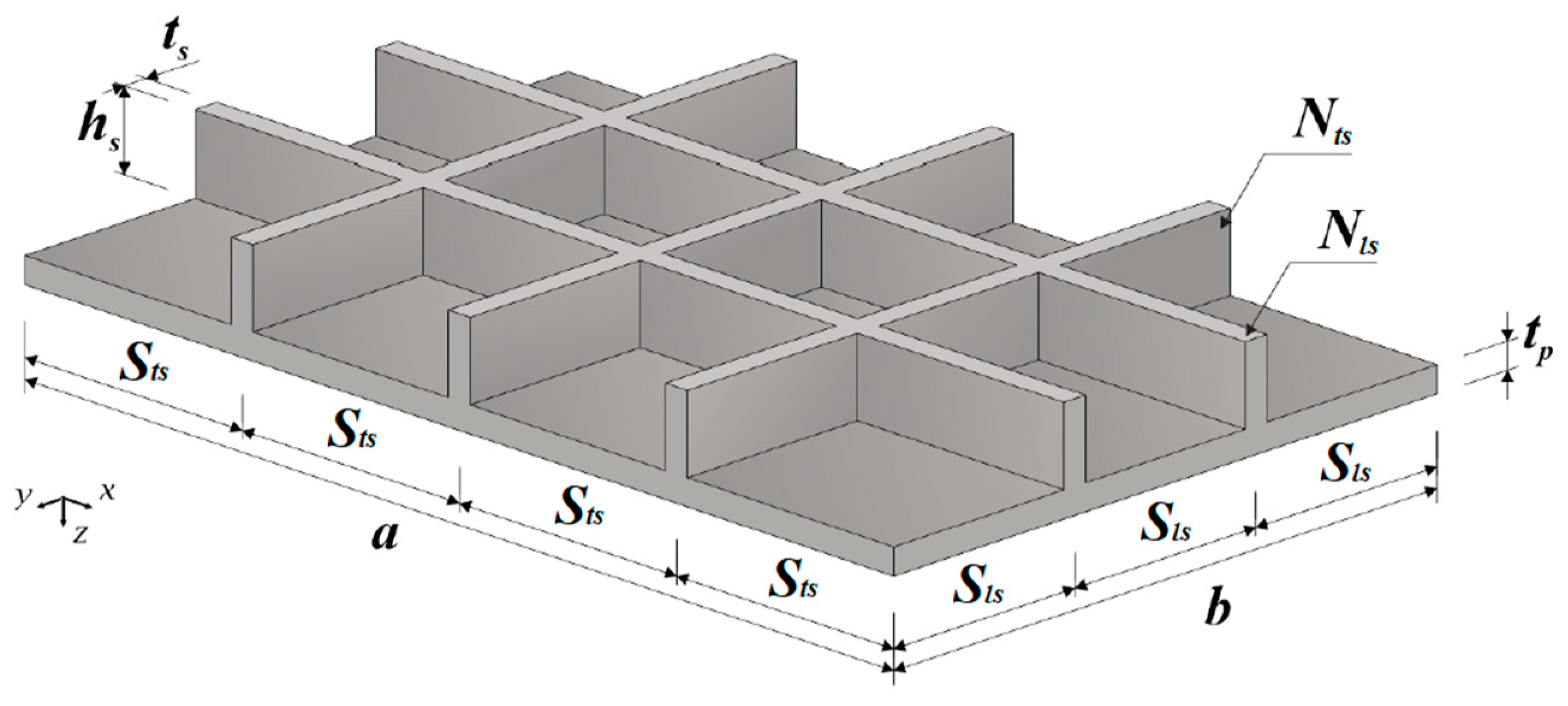
Theory of Stiffened Plates

Salomon [10] presents a division for the analytical approaches for the study of stiffened plates into three broad categories: grillages, orthotropic plate model and plate-beam systems.
According to Salomon [10], the idealization of a plate with stiffeners as a beam grillage requires an effective width of plating varying from 50% to 80% of the spacing between stiffeners. The effective width is the portion of the plate that is used, along with the stiffener cross section, to calculate the moment of inertia as well as the bending and torsional stiffness of the plate. When comparing with the experimental values, the application of this method gives a difference of deflection values between 5% and 10%, and a difference of beam stresses values of generally between 10% and 20%.
In the orthotropic plate approach, the stiffened plate is replaced by an orthotropic non-stiffened plate, which is one the structural properties of which differ along orthogonal axes. This structural anisotropy can be due to manufacturing textures, stiffening beams or even inherent properties of the material.
Similarly to the Kirchhoff plate theory, but now assuming four elastic constants (two modules of elasticity: Ex and Ey; and two Poisson ratios: νx and νy) to describe the stress-strain relations in the x and y directions, the governing equation of orthotropic plates is given by Reference [19]:
D x 4 w x 4 + 2 B 4 w x 2 y 2 + D y 4 w y 4 = p z ( x , y )
where w is the displacement component in z direction; Dx and Dy are the bending stiffness in x and y directions; and B is the effective torsional stiffness of the orthotropic plate.
In order to analyze stiffened plates through the orthotropic plate model, it is necessary to define expressions to determine the sectional bending and torsional properties along the orthotropy direction. Since it is a complicated task to perform, whenever possible, direct tests should be executed in order to determine these properties. However, based on analytical considerations, reasonable approximations can be applied to calculate these stiffnesses, as shown in Szilard [19] and Timoshenko and Woinowsky-Krieger [23] for plates reinforced with rectangular-profile or I shaped beams, corrugated plates and reinforced concrete slabs.
According to Szilard [19], although the real structural behavior of plates reinforced with stiffeners is not exactly replicated by the orthotropic plate model, experimental data indicate a good agreement between results when the stiffeners are small, close and equally spaced.
Lastly, the idealization of stiffened plates as a plate-beam system is the methodology that best reflects the physical problem behavior. In this approach, it is used continuity conditions at the interface between the plate and the reinforcement beams (stiffeners). Due to the mathematical difficulties of analytically solving these problems, this approach was boosted by the advent of digital computers, which enabled the solutions of the models to be obtained through numerical methods. Among the numerical methods, the Finite Element Method (FEM) is the most powerful and effective one to find accurate numerical solutions. Currently, many researchers put effort into developing efficient and accurate FEM models for plates reinforced by stiffeners [10].

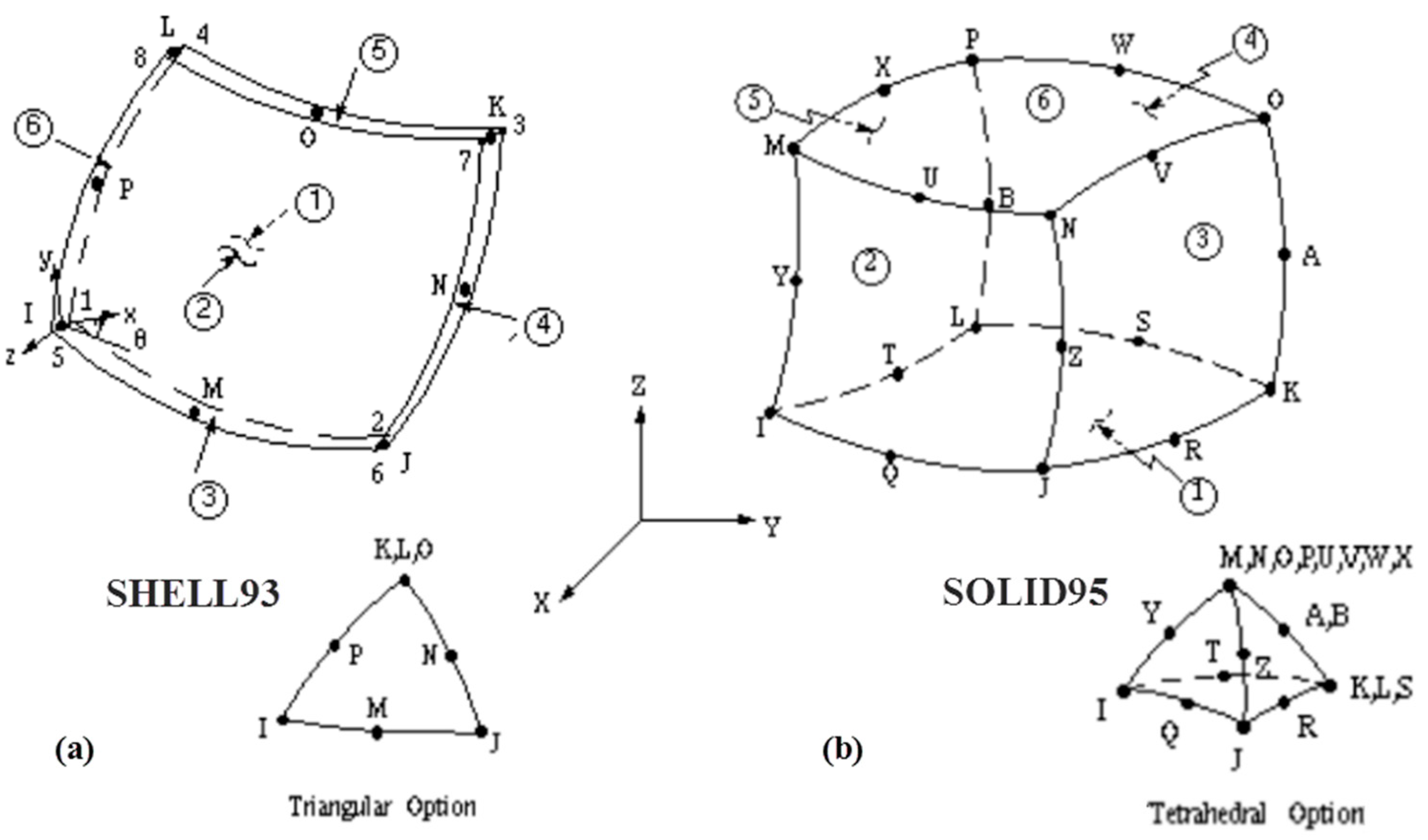
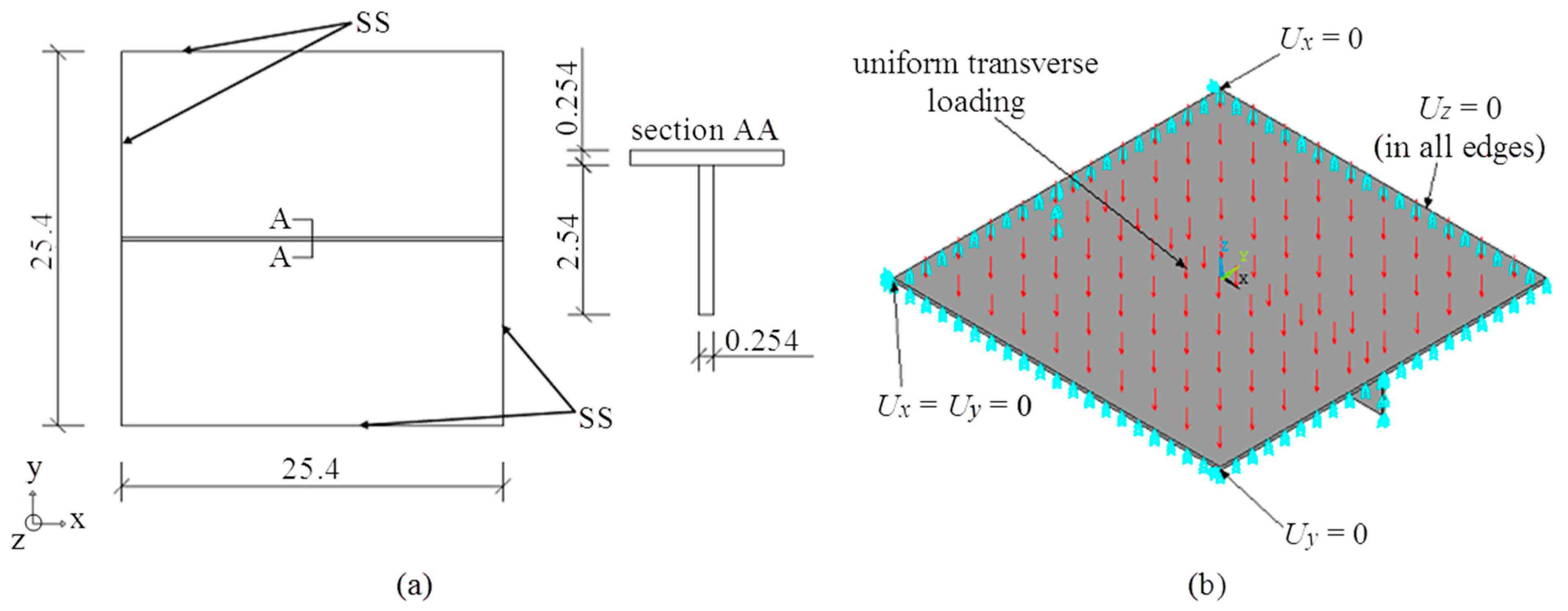
3. Computational Modeling

Computational modeling is used to numerically study a wide range of engineering complex problems, whose governing equations are ordinary or partial differential. Finite Difference Method (FDM), Finite Element Method (FEM) and Finite Volume Method (FVM) are the most employed discretization methods when solving numerical models governed by differential equations. These methods are advantageous over other approaches because they transform differential equations into systems of linear equations, give high quality approximations and are highly flexible in representing complex geometries [26].
The FEM, as defined by Burnett [27], is a computer-aided mathematical technique applied in the obtainment of approximate numerical solutions to abstract equations of calculus that predict the behavior of physical systems when subjected to external influences. This method consists in the following steps: division of the domain into sub-regions (sub-domains called finite elements), transforming the governing differential equation into fine-element algebraic equations and numerically solving the elementary equations through a linear equations system. In the FEM, the continuum domain is idealized as an assemblage of interconnected discrete finite-size elements that behave as a binding mechanism in order to hold the discretized system together. More details about FEM can be found in Schäfer [26], Burnett [27], Gallagher [28], Zienkiewicz and Taylor [29], and Bathe [30].
In the present work, the FEM was employed through the ANSYS® Mechanical APDL software to perform a linear static structural analysis of the central displacements of stiffened plates under uniformly distributed transverse loads.
The ANSYS® software has different types of finite elements available, such as beam elements, plate and shell elements (two-dimensional), and solid elements (three-dimensional). In this work, the computational models for the non-stiffened and stiffened plates were developed using the finite elements SHELL93 and SOLID95.
SHELL93 is suitable to model problems involving plane or curved thin-walled structures (Figure 1a). This quadrilateral element has eight nodes with six degrees of freedom per node: translation in x, y, and z directions and rotation around x, y, and z axis. The used interpolation functions are of the quadratic type. Among the capabilities of this element are the analysis of plasticity, large displacement and large strain. Two important structural considerations are made: the stress normal to the element’s plane varies linearly through the thickness; and the transverse shear stress is constant through the thickness. Moreover, a simplified version of this element is available, where the meshes are generated by triangular shaped elements [31].
SOLID95 is a high-order hexahedral element that can tolerate irregular shapes without significantly losing accuracy (Figure 1b). The element is also well suited to model curved geometries, being defined by twenty nodes with three degrees of freedom per node: translations in x, y, and z nodal directions, having capability to model stress stiffening, large strain, large deflection and creep. It can also be used in its tetrahedral version, with ten nodes [31].
Furthermore, it can be stated that models employing SOLID95 element give more accurate results compared to the ones with SHELL93. It occurs because solid element considers the complete three-dimensional stress and strain states of a solid body, whereas the two-dimensional element has inherent simplifications of assuming plane stress and plane strain states [31].
In the present study, as already mentioned, the ASTM A36 steel with linear-elastic behavior was considered. However, the ANSYS® software can perform static or dynamic simulations of structural components of any metallic material, considering linear or nonlinear mechanical behavior [31].

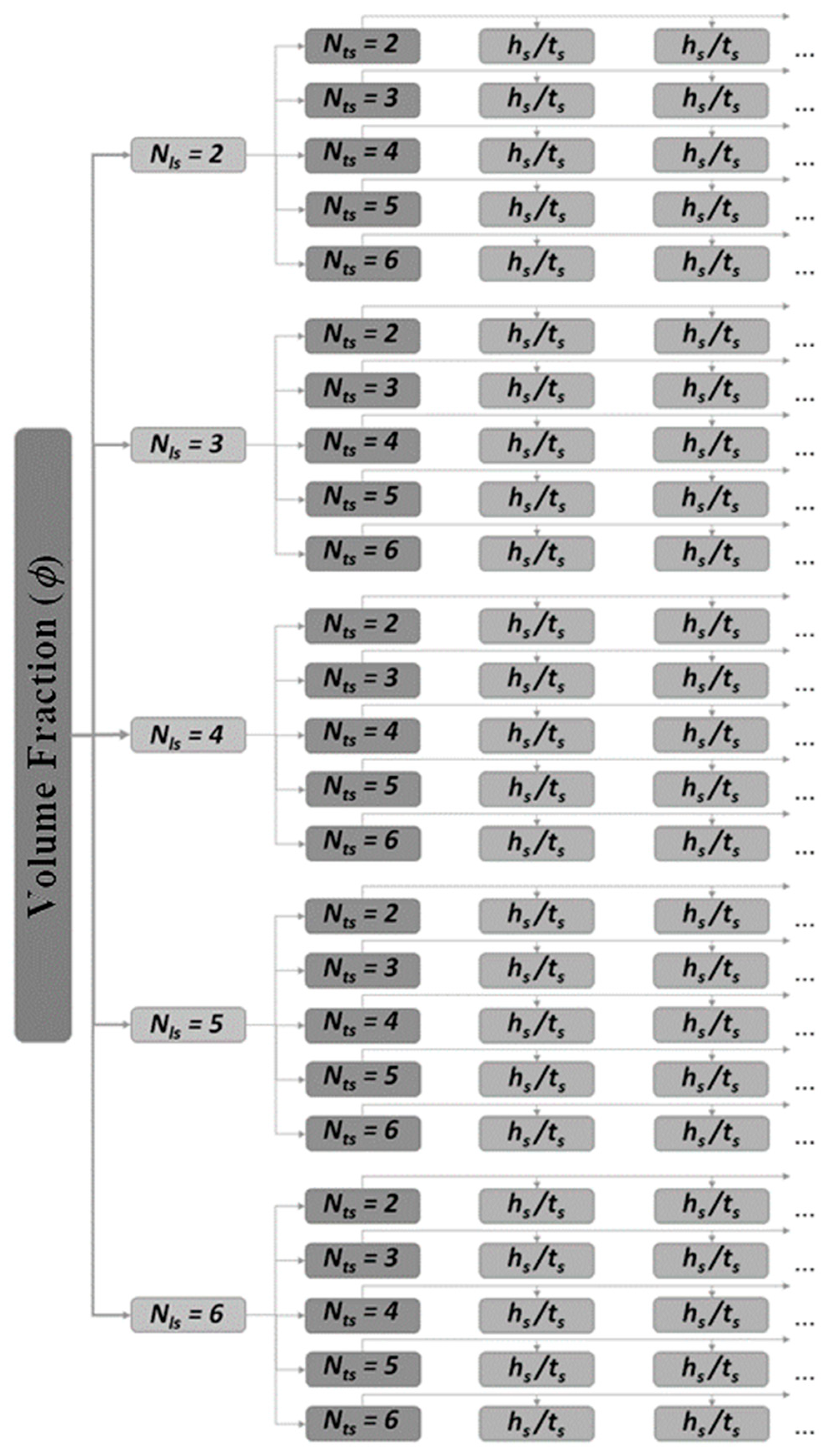
4. Constructal Design Method

The Constructal Theory, developed by Adrian Bejan, arose from the observation of the shape complexity of natural systems. It presumes that the generation of flow systems’ geometric configurations is a physical phenomenon that is not the result of chance, but rather is based on physical principle called Constructal Law. The cross section of rivers and the way pulmonary veins are interconnected, for instance, and are determined through this principle [32].
Bejan and Lorente [33] stated, through the Constructal Theory, that flow systems are fated to persist imperfectly. Thus, the system evolves so that there is an improvement in the flaws distribution and, hence, the fluid body flows easily. Therefore, the natural phenomenon continually evolves not to eliminate the imperfections but actually to distribute them in order to generate a less imperfect geometrical configuration.
For the application of the Constructal Theory in the analysis of mechanical structures, a similar approach is used to the one considered in flow configurations, where the flow is related with the flow of stresses in the solid component. For instance, the geometric configuration for the structure resulting from the application of this principle is the one that has less stress concentration regions, which is obtained when the stresses are distributed throughout the material, according with the Constructal Law [33].
The Constructal Law is employed through the Constructal Design Method (CDM), which guides the engineer to obtain flow configurations that have the best global performance, under specific conditions [33].
In order to apply the CDM in the problem of stiffened plates subjected to a transverse loading, a flat steel plate without stiffeners having length a = 2000 mm, width b = 1000 mm and thickness t = 20 mm was adopted as reference. From the reference plate a volume fraction φ of its thickness was used to generate different combinations of longitudinal Nls and transverse Nts rectangular stiffeners, considering different values for the hs/ts ratio, being hs and ts the height and thickness of the stiffeners, respectively. Thus, the stiffened plates have the thickness tp dependent on the parameter φ and the thickness ts dependent on the commercial values of adopted steel plates. Figure 2 shows an example of stiffened plate with Nls = 2 and Nts = 3, where these geometric parameters are depicted.
The volume fraction φ of material taken from the reference plate to generate the stiffeners is a constraint parameter of the Constructal Design method, being defined as:
φ = V s V r = N l s ( a h s t s ) + N t s [ ( b N l s t s ) h s t s ] a b t
where Vs is the volume of the reference plate transformed into stiffeners and Vr is the total volume of the non-stiffened plate used as reference.
The length a and the width b of the reference plate are also adopted as constraints, since they are usually project parameters. Therefore, the volume fraction to be transformed into stiffeners was taken only from the reference plate thickness t. Thus, all plates have the same length and width and all geometric configurations have the same amount of steel, enabling a comparative evaluation of them to be performed.
In addition to the restrictions above mentioned, the application of the Constructal Design needs the definition of degrees of freedom, which in this problem are: hs/ts (ratio between height and thickness of the stiffeners); Nls (number of longitudinal stiffeners); and Nts (number of transverse stiffeners). As illustrated in Figure 2, it is worth mentioning that all stiffeners have rectangular cross section, same height, and uniform longitudinal (Sls) and transverse (Sts) spacing, respectively, given by:
S l s = b ( N l s + 1 )
S t s = a ( N t s + 1 )
Five values for the volume fraction were considered: φ = 0.1, 0.2, 0.3, 0.4, and 0.5. For each φ value, 25 combinations of longitudinal and transverse stiffeners were analyzed, according with the notation P(Nls,Nts), through the variation of the following degrees of freedom: Nls = 2, 3, 4, 5, and 6 and Nts = 2, 3, 4, 5, and 6. Moreover, stiffeners thickness according to standard sizes of commercial steel plates were adopted and therefore the stiffeners height hs and the ratio hs/ts derive from these predefined ts sizes.
The stiffeners heights hs of the different geometric configurations were obtained through the Equation (2). However, only those cases that respected the following geometric limitations were simulated: hs < 0.3 m (avoiding a disproportion between the height of the stiffener and the planar dimensions of the plate) and hs/ts > 1 (in order to avoid the stiffener thickness from being greater than its height).
Summarizing, the schematic diagram in Figure 3 shows the geometric configurations derived from the application of CDM for each volume fraction φ analyzed, which were simulated in the ANSYS® software Ver 19.3 (ANSYS, Inc., Canonsburg, PA, US).
It is worth highlighting that the CDM application in engineering problems related to fluid mechanics and/or heat transfer areas is a recognized and consecrated procedure for the geometric evaluation as well as geometric optimization. This fact can be proved due the numerous publications about it that can be found in the literature. With the purpose of exemplify the versatility of the CDM in these engineering areas, some recent studies (from 2017 to 2020) are summarized in Table 2.
However, the CDM application in structural engineering problems has not been properly explored by the scientific community. Nowadays, there are few publications on this topic, but it is possible to cite Bejan and Lorente [33], Bejan et al. [54], Lorente et al. [55], and Isoldi et al. [56] where, by means of analogies among heat transfer, fluid mechanics, and mechanics of materials, it was conceptually proven that the CDM is also applicable in structural engineering problems. There are also works dedicated to investigating the influence of geometric configurations of plates submitted to elastic or elasto-plastic buckling: Isoldi et al. [57], Rocha et al. [58], Helbig et al. [59], Lorenzini et al. [60], Helbig et al. [61], Helbig et al. [62], Da Silva et al. [63], and Lima et al. [64,65]; while in Cunha et al. [66], De Queiroz et al. [13], Amaral et al. [67], and Pinto et al. [68] the influence of geometry of stiffened plates was analyzed when submitted to bending. Finally, Mardanpour et al. [69] and Izadpanahi et al. [70] applied the CDM in a study about aircraft structures.

5. Results and Discussion

Initially, convergence mesh tests and verifications for the developed computational models were carried out. After that, the verified computational models were used to numerically simulate the geometric configurations of stiffened plates indicated in Figure 3, and the results analyzed and discussed.

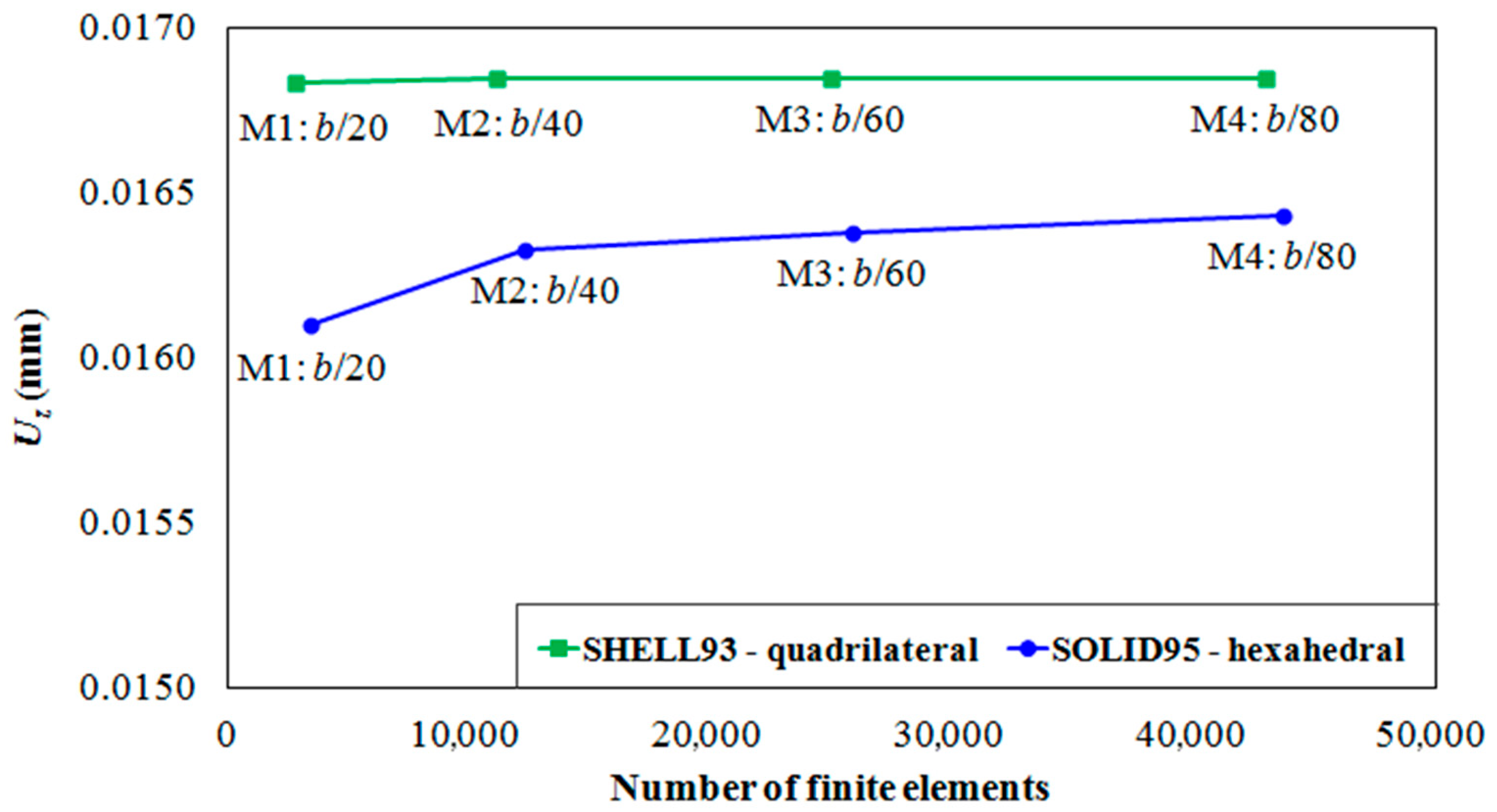
5.1. Mesh Convergence Test and Verification of Computational Models

In the present research, the verification procedure of each numerical model developed into ANSYS® was performed in order to evaluate its capability in determining the central deflection of stiffened plates under a uniformly distributed transverse load. The verification was carried out comparing the obtained numerical result in the present study with those from other researches and, when possible, with analytical solution. Before that, a mesh convergence test was performed, aiming to find the numerical solution non-mesh dependent, being the solution used for the computational verification of each model.
To achieve this, different cases of plates with and without stiffeners were analyzed: rectangular plate without stiffeners (reference plate), square plate with a central stiffener, and a square plate with orthogonal stiffeners. The computational models were discretized with two-dimensional (SHELL93) and three-dimensional (SOLID95) finite elements, as earlier mentioned. Moreover, triangular and quadrilateral shapes for SHELL93 were adopted, as well as tetrahedral and hexahedral shapes for SOLID95.

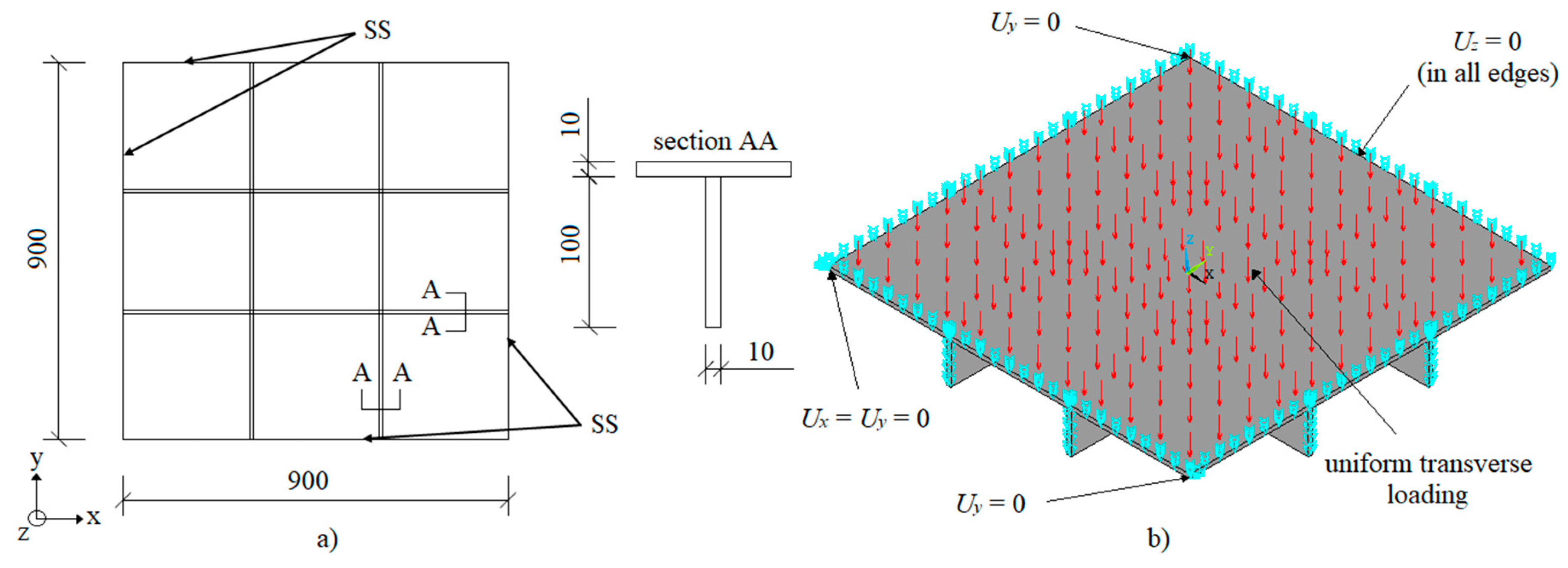
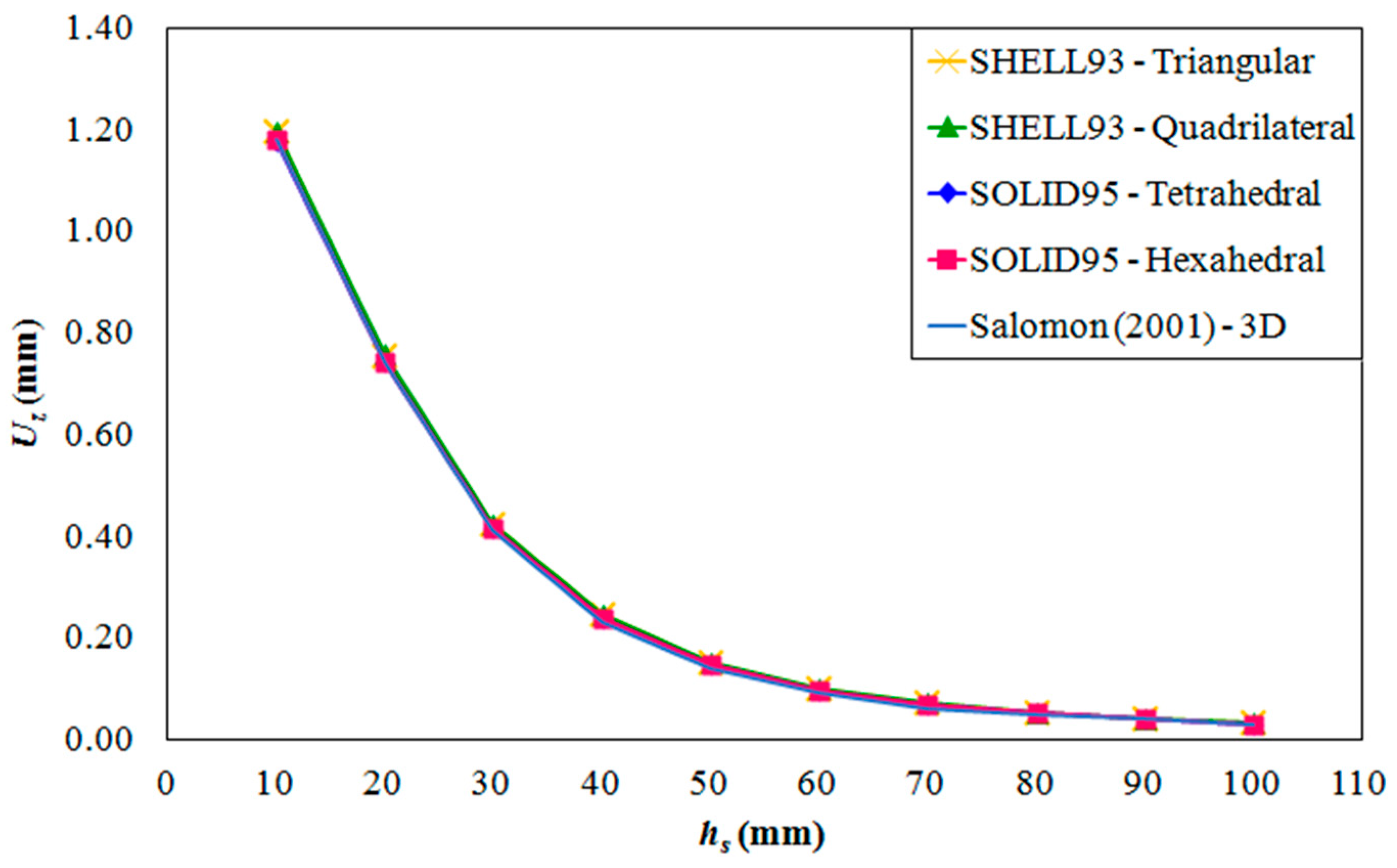
5.1.1. Rectangular Plate without Stiffeners (Reference Plate)

The first mesh convergence/verification was performed analyzing a simply supported (SS) rectangular steel plate without stiffeners, being this the reference plate. A uniform load of 10 kN/m2 was applied transversally to the plate (in z direction). As for the plate’s material, the ASTM A36 steel has Elastic Modulus E = 200 GPa and Poisson’s ratio ν = 0.3. Figure 4 presents the dimensions and the boundary and load conditions of the analyzed case.
The analytical solution for this problem can be obtained from the Lévy method presented in Timoshenko and Woinowsky-Krieger [23], providing a central plate deflection of Uz = 0.698 mm.
Regarding the numerical solutions, the occurrence of mesh convergence with the coarser tested meshes can be observed in Figure 5. The exception happened with the tetrahedral SOLID95 model, being necessarily a more refined mesh to obtain a converged solution. Moreover, one can note that the converged obtained results narrowly agree with the analytical solution and, therefore, it can be stated that the computational models for the plate without stiffeners were properly verified.

5.1.2. Square Plate with a Central Stiffener

This evaluation of the computational models for stiffened plates was based on the works of Rossow and Ibrahimkhail [6] and Tanaka and Bercin [8]. The case, which was also studied by Silva [12], consists in a thin square plate with a central stiffener. The plate’s material is a metallic alloy which has E = 117.21 GPa and ν = 0.3. The plate was simply supported (SS) in the edges (including the stiffener’s ends), being submitted to a transverse uniform distributed load of 6.89 kN/m², as depicted in Figure 6.
In Figure 7 the numerical results obtained with the four proposed computational models are compared with those presented by Rossow and Ibrahimkhail [6], Tanaka and Bercin [8] and Silva [12].
From Figure 7, the mesh convergence test indicates a good agreement among all proposed models in the present work, highlighting that it was not necessary to use more refined meshes to achieve the independent mesh solutions for this case. The only exception again was the tetrahedral SOLID95 model, which requires a more refined mesh to reach convergence. Additionally, the obtained numerical converged results were compared to the solutions found in the aforementioned references. In order to obtain the solutions, each author used a different approach, as previously indicated in the introductory section. Considering these solutions, it is possible to consider the proposed numerical models verified.

5.1.3. Square Plate with Orthogonal Stiffeners

Lastly, we simulated a square thin plate reinforced with orthogonal stiffeners located as shown in Figure 8. The structure consists of a plate and two sets of orthogonal stiffeners, being subjected to a uniform pressure of 9.8 kN/m². The plate edges, including the stiffeners ends, were considered as simply supported (SS). The steel alloy mechanical properties of the plate’s material are E = 210 GPa and ν = 0.3.
This case was also numerically analyzed by Salomon [10] through four types of computational models developed and solved using the finite element software ADINA®. As stated by Salomon [10], the solution of a three-dimensional (3D) model provides the best response prediction of the real structure, since the model does not include pre-defined assumptions about the mechanics of the structure. Therefore, only the 3D numerical solution of Salomon [10], obtained from a 27-node finite element, was taken into account. Figure 9 shows this result confronted with those obtained by the present study.
According to Figure 9, one can infer that the values obtained with the computational models of the present work are convergent, having the same trend observed in previous cases. Furthermore, they are similar to the value found by the reference used to comparison and, as expected, displacements with SHELL93 models were slightly greater than the displacements with the other models, since 2D models present less structural rigidity due to the assumed assumptions of the structure mechanics for thin plates.
The analytical solution presented by Salomon [10] was also included in Figure 9. This solution can be obtained by the application of Equation (1) derived from the orthotropic plate approach (see Section 2), and has, despite the difference, the same order of magnitude of the numerical solutions.
With the purpose to verify, once more, the proposed computational models based on the comparison of results with Salomon [10], it was simulated stiffened plates (see Figure 8) with different stiffeners heights (varying from 10 mm to 100 mm, with increment of 10 mm). These results are presented in Figure 10, showing superimposed results that indicated an excellent agreement among the solutions of the proposed models with the solution of the 3D model used by Salomon [10], allowing us to affirm that the computational models developed in this work were properly verified.

5.2. Case Study

In order to generate the results of this research, only the numerical models SHELL93–quadrilateral and SOLID95–hexahedral were used, because they presented better accuracy and computational efficiency in the simulations developed in the mesh convergence and verification tests (see Section 5.1).
To ensure the adequate mesh refinement to be used in the numerical simulations, convergence tests for each studied φ (volume fraction) were performed. In the executed tests, the most complex geometries were used, i.e., the plates P(6,6) with the thinnest stiffener’s thickness. Besides, we applied the same boundary and load conditions as employed in all analyzed plates, namely, simply supported edges and uniformly distributed load of 10 kN/m2.
In the mesh convergence tests, four different mesh refinements were used: M1; M2; M3; and M4, where the element size in each mesh is a fraction of the plate’s width (M1 = b/20; M2 = b/40; M3 = b/60; and M4 = b/80). To illustrate these mesh convergence tests, Figure 11 shows the results for both models SHELL93–quadrilateral and SOLID95–hexahedral for φ = 0.5, and it is possible to observe the convergence from the mesh M3 for both element types. Furthermore, the convergence criterion was also reached in the mesh M3 for all φ under analysis. Thus, the meshes used throughout this research have an element size of 1/60 of the plate’s width (16.67 mm).
Thereafter, the proposed stiffened plates were numerically simulated. As early mentioned, a simply supported non-stiffened steel plate, with t = 20 mm, b = 1 m, a = 2 m, E = 200 GPa and ν = 0.3, was adopted as reference. Regarding the load conditions, the plate was subjected to a uniform load of 10 kN/m². The geometrical configurations of the stiffened plates were defined by transforming part of the reference plate into stiffeners. The stiffeners’ thicknesses were defined based on commercial values of steel plates, varying from 1/8 in (3.18 mm) to 3 in (76.20 mm).
Then, scatter charts, representing the variation of the plates’ central deflection, for each P(Nls, Nts), as a function of the degree of freedom hs/ts, were plotted. To illustrate the results, Figure 12 shows the aforementioned graphs for the volume fraction φ = 0.5.
From Figure 12 one can notice that the mere transformation of a portion of steel from the reference plate into stiffeners enhanced the mechanical behavior (regarding the central deflection) of all stiffened plates, since all analyzed configurations presented a displacement lower than the reference plate’s one (see Section 5.1.1).
Through the graphs of Figure 12, it was also noted that an increase in the ratio hs/ts entails a reduction in the central out-of-plane displacement Uz of the plates. This occurs because as hs/ts increases, the moment of inertia of the new defined structures also increases.
In addition, it was possible to adjust power curves to the numerical results that mathematically described the relation between the central deflection Uz and ratio hs/ts with great accuracy. To do so, the following general equation was defined:
U z = C 1 ( h s t s ) C 2
where C1 and C2 are constants that depend on the number of longitudinal Nls and transverse Nts stiffeners.
To exemplify the performed curve fitting, Figure 13 presents the power curves that best fitted the data for the plates P(6,2) and P(6,5) with φ = 0.5 and SHELL93–quadrilateral and SOLID95–hexahedral elements type. Moreover, the same figure presents the determination coefficient R², which indicates how well the curve fits the obtained data. In both cases, the plates P(6,2) and P(6,5) had coefficients R² superior to 0.99 (or 99%).
In Appendix A we present the coefficients C1; C2; and R² for each studied geometry and for all volume fractions, as well as the range of degree of freedom hs/ts that was numerically simulated. It is important to note that all values of C2 are negative, which means that the central deflection decreases as the relation hs/ts increases, corroborating with the behavior observed in the graphs of Figure 12.
Moreover, an important find which emerges from Figure 13a is that when comparing, for instance, the results of P(6,2) with hs/ts = 1.02 in relation to P(6,2) with hs/ts = 35.62, both with SHELL93 model, there is a nearly 94% reduction in transverse displacement in the center of the stiffened plate. Therefore, since the amount of steel used in the manufacture of these stiffened plates is kept constant, one can state that considerable improvements in structural rigidity can be achieved only due to the influence of its geometric configuration variation. It is worth mentioning that this trend occurs for all stiffened plates arrangements considered in this work.
Taking into account that the Constructal Design method is able to evaluate the influence of the geometric parameters (degrees of freedom) on the mechanical behavior regarding the deflection of the stiffened plates under analysis, so the degrees of freedom Nls, Nts, and hs/ts were evaluated seeking the lowest central deflection among all studied geometrical configurations, for each adopted volume fraction φ.
Initially, it was determined the optimal relation hs/ts, called (hs/ts)o, i.e., the ratio hs/ts that leads to the minimized central displacements, called (Uz)m, for each combination of P(Nls,Nts). The graphs in Figure 14 show the minimized central deflections of the stiffened plates, considering each combination of the number of longitudinal Nls and the number of transverse Nts stiffeners. It is important to highlight that the lines in Figure 14 are adopted only to aid the visualization of how Nts influences the central deflection. Obviously, these lines do not indicate or represent continuity among the discrete values of Nts variation.
Figure 14 indicates that an increase in the number of stiffeners does not necessarily mean an improvement in the plate’s stiffness. By keeping the volume of material constant, the increase in the number of stiffeners decreases the reinforcements’ height and its cross-sectional moment of inertia and hence reduces the stiffness of the structure. Another important observation is that the results showed an oscillation trend, where plates with an odd number of transverse stiffeners presented better results than those with an even Nts. This trend is explained by the fact that plates with and odd Nts have a stiffener at its very center, reducing, therefore, the deflection in the structure’s geometric center.
For both models (SHELL93 and SOLID95) and each Nls, it was possible determining the optimal number of transverse stiffeners (Nts)o, which is the Nts that leads to a twice minimized central deflection of the plates, called (Uz)mm. Consequently, the twice optimized ratio hs/ts, called (hs/ts)oo was also defined. Table 3 shows the aforementioned parameters for each volume fraction φ.
One can note, from Table 3, that the displacements (Uz)mm tend to higher values as the degree of freedom Nls increases. This happens due to the application of the Constructal Design method, the main restriction of which is to keep the total volume of material constant in all analyzed geometric configurations. By keeping the total volume of steel constant, the stiffeners’ height must be reduced in order to increase the Nls, directly affecting the moment of inertia.
Based on results of Table 3, it is possible to determine the three-times optimized geometric configuration for each analyzed volume fraction φ. To illustrate this, for φ = 0.1, the optimized geometry is the plate P(2,3), with three-times optimized ratio (hs/ts)ooo = 56.66, which presented a three-times minimized (Uz)mmm = 0.0652 mm for the simulations with SHELL93 elements and (Uz)mmm = 0.0639 mm with SOLID95. For the volume fractions φ = 0.2; 0.3; 0.4; and 0.5, the best geometrical configuration was the plate with geometric configuration P(2,5), which caused uniform spacing in longitudinal and transverse directions (see Figure 2) defined as Sls = Sts = 0.333 m.
Lastly, we performed an evaluation of the influence of φ on the results of the central displacement of the stiffened plates, with it being possible to identify, among all studied stiffened plates configurations, the one that achieves superior performance. Figure 15 shows the three-times minimized central deflection (Uz)mmm for each analyzed volume fraction.
From Figure 15, it is possible to observe that there was not a significant difference among the results of the plates’ central deflections for volume fractions within the range 0.3 ≤ φ ≤ 0.5. Moreover, we determined the plate with the best global performance (depicted in Figure 16) among all cases analyzed in the present work, demonstrating that the best configuration is the plate with optimized φo = 0.5, four-times optimized ratio (hs/ts)oooo = 35.03, three-times optimized (Nts)ooo = 5 and twice optimized (Nls)oo = 2, which presented four-times minimized displacement (Uz)mmmm = 0.0086 and (Uz)mmmm = 0.0084 mm for the models with SHELL93 and SOLID95, respectively.
Therefore, the geometry with the best mechanical performance among all analyzed stiffened plates provided a reduction in the transverse central deflection of 98.77% in comparison with the non-stiffened reference plate. In other words, the optimal geometry presented a displacement 81-times smaller than the one presented by the reference plate. Thus, significant improvements in the structural performance of the stiffened plates were reached when changing the geometric configuration of these structures.

6. Further Considerations

This paper allied the computational modeling, Constructal Design Method and Exhaustive Search technique in the geometric evaluation of stiffened steel plates. From the generated results, the following considerations emerge:
  • Despite keeping the same steel volume, same dimensions (except thickness), same load and same support conditions, in a general way, all proposed stiffened plates presented lower central deflection when compared with non-stiffened reference plate. Those apparently obvious results demonstrate how the proposed method is in the right direction toward the correct prediction of physical effects. Furthermore, they show how, for a fixed amount of weight, stiffened plates are more efficient. Adequate stiffening is therefore necessary. Welding techniques are also required.
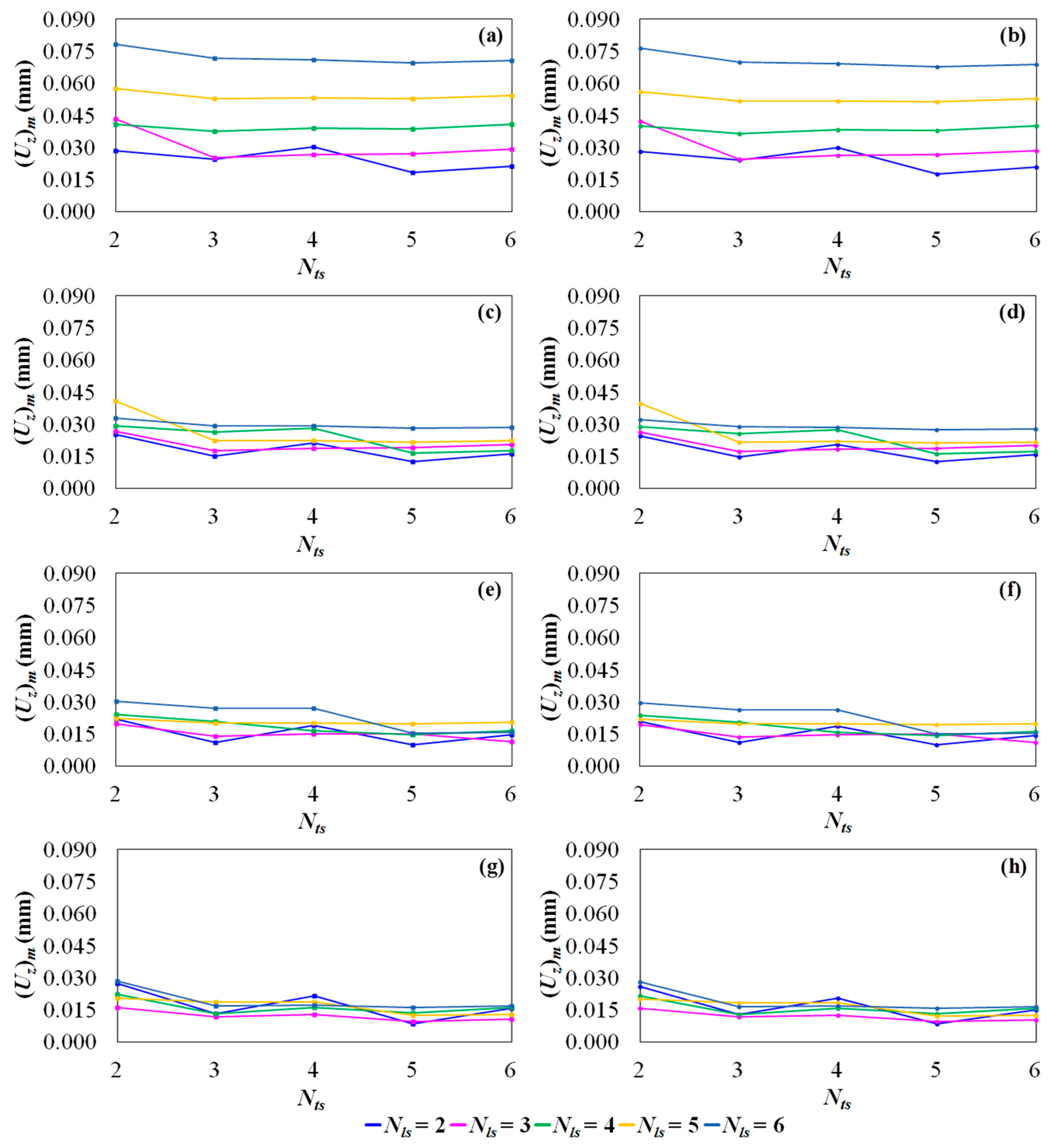
  • The number of transverse stiffeners (Nts), number of longitudinal stiffeners (Nls), and ratio between height and thickness of stiffeners (hs/ts) have a deep influence on plates’ stiffness and hence in its deflections. These results also permit us to give additional trust to the method, confirming an obvious physical reality regarding the fact that more stiffeners influence the response of the plate.
  • For stiffened plates fabricated with the same amount of steel volume, the increase in the number of stiffeners does not necessarily imply a reduction of its central deflection, highlighting the importance of performing studies involving geometric evaluation in order to efficiently use the material when projecting and constructing these kind of structures.
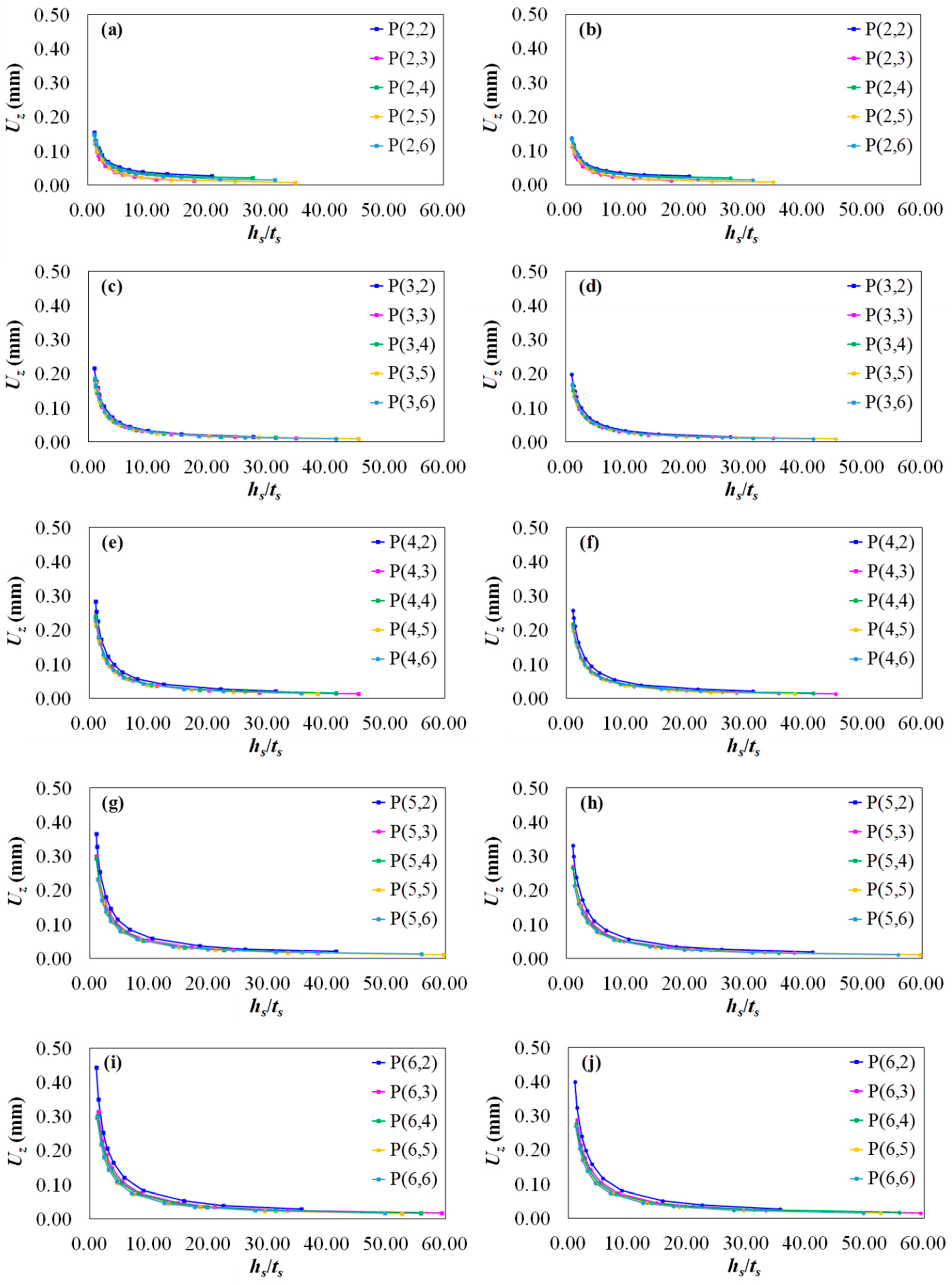
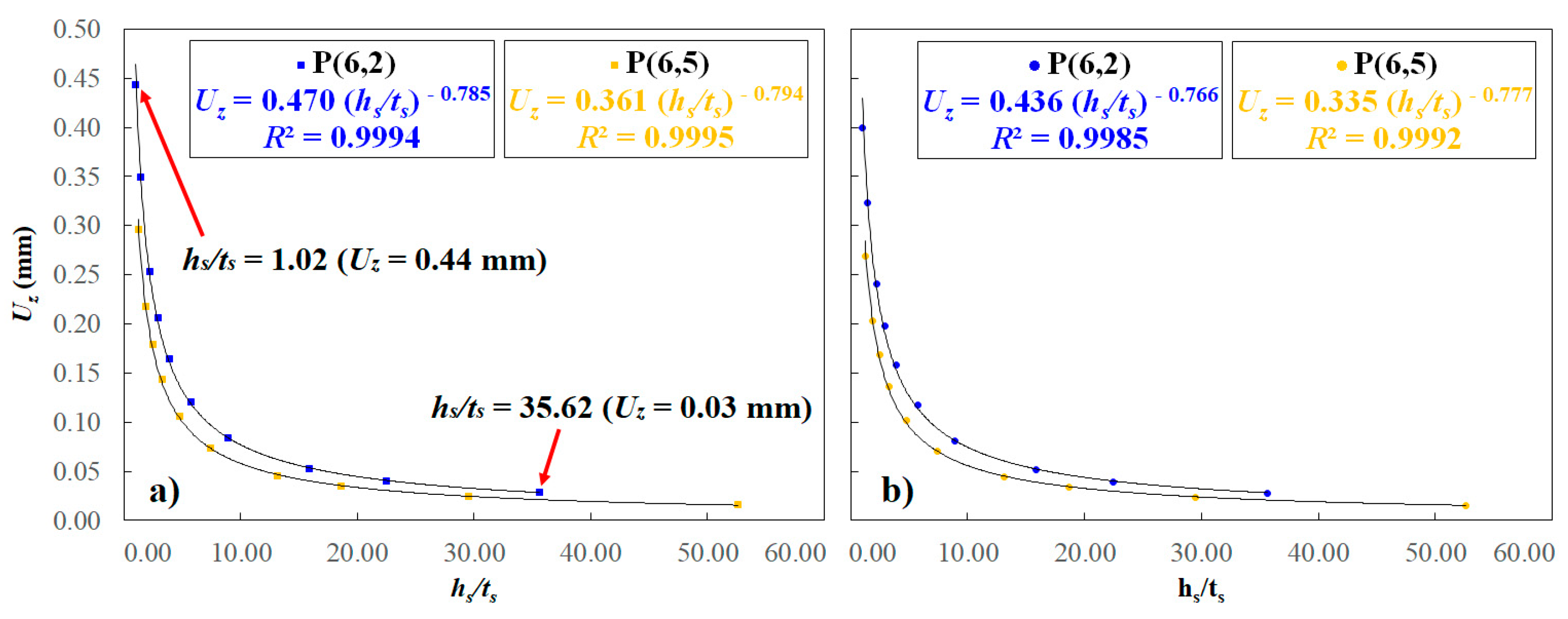
  • In a general way, the central deflection values for the stiffened plates tend to stabilize as the ratio hs/ts increases. This asymptotic trend indicates that for values of hs/ts ≥ 20 there is no significant reduction of central transverse displacement. It is an important finding because over-incrementing hs/ts can be harmful to the structure as it increases the reinforcements’ slenderness and, consequently, intensifies the mechanical element’s propensity to instability problems (local buckling).
  • For each combination of Nls and Nts a power curve was fitted to mathematically describe the relation between the central displacement and the ratio hs/ts. The coefficients of determination R² presented values from 92% up to 99.99%, evidencing the great accuracy of the performed curve fitting. The equations derived from these curves are highly useful in determining the central displacements of the plates for values of hs/ts within the simulated range and even to extrapolate these results for different values of hs/ts.
  • The global optimized stiffened plate, i.e., the best performance among all analyzed geometric configurations, was the one with optimized φo = 0.5, four-times optimized (hs/ts)oooo = 35.03, three times optimized (Nts)ooo = 5 and twice optimized (Nls)oo = 2, which presented a four-times minimized deflection of (Uz)mmmm = 0.0086 mm for the simulation performed using SHELL93 elements and (Uz)mmmm = 0.0084 mm for the simulation with SOLID95 elements. This geometric configuration reached a reduction of 98.77% in the transverse central displacement, if compared with the reference plate.
  • Concerning the excellent convergence between the obtained results for both numerical models (SHELL93 and SOLID95), one can indicate the employment of shell finite element for stiffened plate simulations, since it has accuracy and needs a somewhat lower amount of processing time.
  • Through the application of the Constructal Design Method, recommendations were obtained about the best geometric configurations of stiffened plates with the aim of minimizing the central out-of-plane displacement of these structures. In addition, it was also possible to draw conclusions which can serve as a support for researches related to this topic, about the mechanical behavior of structures composed of plates and stiffeners.
  • The present study specifically considered the mechanical behavior related to the transverse displacements of plates. To do so, an ideal structure (with no imperfections) having a linear (geometric and material) behavior was considered. This simple approach was adopted, aiming to show the applicability of the CDM in this kind of engineering problem. Therefore, in future works a stress analysis, as well as a Geometrically and Materially Nonlinear Analysis with Imperfections Included (GMNIA), can be performed. Moreover, other geometric parameters can be varied, other types of stiffeners can be investigated, and other types of metallic alloys can be tested.

7. Conclusions

Here we presented and discussed in detail a new computational method employed for modeling of thin steel plates with stiffeners subjected to uniform transverse loads. Stiffened thin steel plates are commonly used in a large range on engineering sectors (such as aeronautical, civil, naval or offshore engineering). Specifically, an approach associating Constructal Design Method and Exhaustive Search technique was here developed, merged in a computational model, validated and then applied with the scope to minimize the central deflections of these plates. A non-stiffened plate was adopted as reference for validation, but also for a plain comprehension of outcomes. Various values for the stiffeners volume fraction (φ) were investigated searching for their influence, together with the configuration providing the best structural performance. In these terms, the number of longitudinal and transverse stiffeners, and the aspect ratio of stiffener shape were considered as degrees of freedom. For several combinations of these parameters, the optimized plates were determined showing, in some cases, a deflection reduction of over 90%.

Author Contributions

Conceptualization, G.T., E.d.S., L.I., L.R.; methodology, G.T., M.C., V.P.; software, G.T., M.C.; validation, G.T., M.C., L.I.; formal analysis, L.R., E.d.S., C.F., L.I.; investigation, G.T., M.C., E.d.S. and L.I.; resources, E.d.S., C.F. and L.I.; data curation, L.I.; writing—original draft preparation, G.T., M.C. and V.P.; writing—review and editing, V.P., L.I. and C.F.; visualization, L.R., C.F. and E.d.S; supervision, L.R. and L.I.; project administration, E.d.S., C.F. and L.I. All authors have read and agreed to the published version of the manuscript.

Funding

The authors thank FAPERGS (Research Support Foundation of Rio Grande do Sul), CNPq (Brazilian National Council for Scientific and Technological Development), CAPES (Brazilian Coordination for Improvement of Higher Education Personnel) and MAECI (Italian Ministry of Foreign Affairs and International Cooperation) for their institutional and financial supports. In particular, E. dos Santos, L. Isoldi, and L. Rocha thank CNPq for research grants (Processes: 306024/2017-9, 306012/2017-0, and 307847/2015-2, respectively).

Conflicts of Interest

The authors declare no conflict of interest.

Appendix A

Table A1. Values of C1; C2; and R² for φ = 0.1.
P(Nls,Nts)hs/ts rangeSHELL93SOLID95
C1C2R2C1C2R2
P(2,2)1.05 ≤ hs/ts ≤ 66.070.663−0.5190.98540.650−0.5180.9840
P(2,3)1.18 ≤ hs/ts ≤ 56.660.666−0.5420.98310.653−0.5410.9818
P(2,4)1.04 ≤ hs/ts ≤ 49.600.643−0.5110.97920.631−0.5110.9777
P(2,5)1.23 ≤ hs/ts ≤ 44.110.672−0.5240.97900.661−0.5240.9778
P(2,6)1.11 ≤ hs/ts ≤ 39.710.657−0.4990.97500.647−0.4980.9736
P(3,2)1.03 ≤ hs/ts ≤ 49.560.767−0.4480.96640.749−0.4450.9630
P(3,3)1.23 ≤ hs/ts ≤ 44.090.769−0.4710.97040.752−0.4690.9680
P(3,4)1.11 ≤ hs/ts ≤ 39.710.736−0.4540.96710.721−0.4520.9646
P(3,5)1.01 ≤ hs/ts ≤ 36.120.710−0.4400.96310.695−0.4380.9602
P(3,6)1.35 ≤ hs/ts ≤ 33.120.749−0.4570.97030.736−0.4560.9684
P(4,2)1.10 ≤ hs/ts ≤ 39.660.839−0.3840.95220.820−0.3810.9474
P(4,3)1.01 ≤ hs/ts ≤ 36.080.790−0.3860.95120.770−0.3830.9463
P(4,4)1.35 ≤ hs/ts ≤ 33.100.820−0.4100.96230.804−0.4080.9595
P(4,5)1.25 ≤ hs/ts ≤ 30.580.789−0.4010.96000.773−0.3990.9569
P(4,6)1.26 ≤ hs/ts ≤ 28.410.765−0.3880.95780.750−0.3860.9546
P(5,2)1.34 ≤ hs/ts ≤ 33.050.904−0.3410.94740.884−0.3370.9417
P(5,3)1.24 ≤ hs/ts ≤ 30.540.857−0.3470.94840.836−0.3430.9430
P(5,4)1.16 ≤ hs/ts ≤ 28.380.824−0.3420.94800.805−0.3390.9427
P(5,5)1.08 ≤ hs/ts ≤ 26.510.796−0.3370.94690.777−0.3340.9413
P(5,6)1.02 ≤ hs/ts ≤ 24.870.774−0.3290.94550.756−0.3260.9395
P(6,2)1.15 ≤ hs/ts ≤ 28.330.892−0.2770.93140.869−0.2720.9217
P(6,3)1.07 ≤ hs/ts ≤ 26.470.853−0.2860.93410.829−0.2800.9248
P(6,4)1.01 ≤ hs/ts ≤ 24.840.825−0.2850.93480.803−0.2810.9255
P(6,5)1.49 ≤ hs/ts ≤ 23.400.864−0.3200.95580.845−0.3170.9519
P(6,6)1.41 ≤ hs/ts ≤ 22.120.840−0.3150.95530.823−0.3130.9516
Table A2. Values of C1; C2; and R² for φ = 0.2.
P(Nls,Nts)hs/ts RangeSHELL93SOLID95
C1C2R2C1C2R2
P(2,2)1.35 ≤ hs/ts ≤ 59.280.400−0.6600.99870.390−0.6580.9986
P(2,3)1.16 ≤ hs/ts ≤ 50.860.393−0.7060.99850.379−0.7010.9981
P(2,4)1.02 ≤ hs/ts ≤ 44.530.389−0.6690.99820.376−0.6650.9977
P(2,5)1.42 ≤ hs/ts ≤ 88.210.410−0.7010.99890.398−0.6980.9987
P(2,6)1.28 ≤ hs/ts ≤ 79.410.413−0.6810.99860.402−0.6780.9983
P(3,2)1.01 ≤ hs/ts ≤ 44.480.550−0.6570.99560.528−0.6490.9942
P(3,3)1.41 ≤ hs/ts ≤ 88.180.534−0.6820.99830.514−0.6770.9978
P(3,4)1.28 ≤ hs/ts ≤ 79.410.516−0.6720.99770.498−0.6670.9971
P(3,5)1.17 ≤ hs/ts ≤ 72.230.507−0.6730.99650.487−0.6670.9956
P(3,6)1.07 ≤ hs/ts ≤ 66.240.501−0.6630.99540.482−0.6570.9944
P(4,2)1.27 ≤ hs/ts ≤ 79.310.701−0.6370.99550.675−0.6320.9943
P(4,3)1.16 ≤ hs/ts ≤ 72.170.641−0.6470.99420.612−0.6400.9929
P(4,4)1.07 ≤ hs/ts ≤ 66.210.606−0.6350.99360.581−0.6280.9921
P(4,5)1.29 ≤ hs/ts ≤ 61.150.614−0.6530.99420.589−0.6480.9931
P(4,6)1.20 ≤ hs/ts ≤ 56.820.597−0.6420.99330.574−0.6370.9920
P(5,2)1.06 ≤ hs/ts ≤ 66.100.791−0.5970.98820.753−0.5880.9854
P(5,3)1.28 ≤ hs/ts ≤ 61.080.760−0.6230.99090.725−0.6160.9891
P(5,4)1.20 ≤ hs/ts ≤ 56.770.715−0.6180.99030.683−0.6100.9884
P(5,5)1.12 ≤ hs/ts ≤ 53.020.682−0.6150.98890.649−0.6070.9868
P(5,6)1.06 ≤ hs/ts ≤ 49.740.657−0.6070.98780.627−0.5990.9855
P(6,2)1.18 ≤ hs/ts ≤ 56.660.903−0.5720.98390.861−0.5630.9805
P(6,3)1.11 ≤ hs/ts ≤ 52.940.823−0.5800.98390.780−0.5700.9805
P(6,4)1.05 ≤ hs/ts ≤ 49.680.772−0.5760.98360.734−0.5670.9804
P(6,5)1.32 ≤ hs/ts ≤ 46.800.785−0.6010.98710.748−0.5930.9849
P(6,6)1.25 ≤ hs/ts ≤ 44.230.753−0.5940.98630.719−0.5870.9840
Table A3. Values of C1; C2; and R² for φ = 0.3.
P(Nls,Nts)hs/ts RangeSHELL93SOLID95
C1C2R2C1C2R2
P(2,2)1.04 ≤ hs/ts ≤ 31.420.255−0.6880.99890.244−0.6810.9991
P(2,3)1.04 ≤ hs/ts ≤ 42.750.245−0.7530.99950.234−0.7440.9993
P(2,4)1.07 ≤ hs/ts ≤ 37.440.247−0.6950.99890.236−0.6870.9990
P(2,5)1.37 ≤ hs/ts ≤ 59.410.259−0.7540.99920.250−0.7480.9992
P(2,6)1.23 ≤ hs/ts ≤ 53.490.264−0.7190.99890.255−0.7140.9989
P(3,2)1.06 ≤ hs/ts ≤ 37.380.378−0.7340.99920.360−0.7240.9986
P(3,3)1.36 ≤ hs/ts ≤ 59.380.352−0.7450.99930.336−0.7360.9992
P(3,4)1.23 ≤ hs/ts ≤ 53.490.344−0.7380.99930.328−0.7300.9990
P(3,5)1.13 ≤ hs/ts ≤ 48.670.341−0.7450.99910.325−0.7350.9986
P(3,6)1.04 ≤ hs/ts ≤ 44.640.341−0.7380.99880.325−0.7290.9982
P(4,2)1.22 ≤ hs/ts ≤ 53.390.503−0.7180.99890.480−0.7100.9984
P(4,3)1.12 ≤ hs/ts ≤ 48.600.455−0.7320.99860.430−0.7210.9978
P(4,4)1.03 ≤ hs/ts ≤ 44.600.430−0.7170.99840.407−0.7070.9976
P(4,5)1.49 ≤ hs/ts ≤ 91.730.428−0.7320.99910.408−0.7250.9990
P(4,6)1.39 ≤ hs/ts ≤ 85.230.419−0.7200.99910.401−0.7140.9989
P(5,2)1.02 ≤ hs/ts ≤ 44.500.614−0.7040.99670.579−0.6910.9950
P(5,3)1.47 ≤ hs/ts ≤ 91.620.569−0.7230.99900.539−0.7140.9986
P(5,4)1.38 ≤ hs/ts ≤ 85.150.533−0.7180.99890.506−0.7090.9984
P(5,5)1.29 ≤ hs/ts ≤ 79.530.511−0.7210.99860.483−0.7120.9980
P(5,6)1.22 ≤ hs/ts ≤ 74.610.496−0.7170.99830.469−0.7070.9976
P(6,2)1.36 ≤ hs/ts ≤ 84.990.751−0.7000.99790.712−0.6910.9971
P(6,3)1.28 ≤ hs/ts ≤ 79.410.667−0.7080.99770.627−0.6970.9967
P(6,4)1.21 ≤ hs/ts ≤ 74.520.618−0.7020.99760.583−0.6920.9966
P(6,5)1.14 ≤ hs/ts ≤ 70.200.586−0.7050.99700.550−0.6930.9958
P(6,6)1.09 ≤ hs/ts ≤ 66.350.562−0.6990.99670.529−0.6880.9954
Table A4. Values of C1; C2; and R² for φ = 0.4.
P(Nls,Nts)hs/ts RangeSHELL93SOLID95
C1C2R2C1C2R2
P(2,2)1.07 ≤ hs/ts ≤ 29.550.184−0.6620.99520.172−0.6530.9956
P(2,3)1.20 ≤ hs/ts ≤ 35.960.175−0.7840.99940.165−0.7720.9995
P(2,4)1.06 ≤ hs/ts ≤ 31.500.176−0.6720.99620.165−0.6600.9966
P(2,5)1.09 ≤ hs/ts ≤ 44.400.183−0.7810.99940.174−0.7710.9995
P(2,6)1.15 ≤ hs/ts ≤ 39.980.187−0.7140.99790.178−0.7060.9981
P(3,2)1.04 ≤ hs/ts ≤ 31.440.275−0.7710.99970.260−0.7560.9995
P(3,3)1.09 ≤ hs/ts ≤ 44.370.250−0.7750.99960.235−0.7600.9994
P(3,4)1.15 ≤ hs/ts ≤ 39.980.247−0.7710.99950.233−0.7600.9994
P(3,5)1.06 ≤ hs/ts ≤ 36.390.246−0.7810.99960.232−0.7670.9993
P(3,6)1.38 ≤ hs/ts ≤ 59.520.248−0.7700.99910.237−0.7620.9991
P(4,2)1.14 ≤ hs/ts ≤ 39.880.371−0.7510.99950.351−0.7390.9992
P(4,3)1.04 ≤ hs/ts ≤ 36.320.334−0.7750.99940.312−0.7590.9989
P(4,4)1.38 ≤ hs/ts ≤ 59.470.314−0.7420.99870.298−0.7330.9988
P(4,5)1.28 ≤ hs/ts ≤ 54.950.313−0.7730.99950.295−0.7620.9993
P(4,6)1.19 ≤ hs/ts ≤ 51.070.307−0.7540.99930.290−0.7440.9992
P(5,2)1.35 ≤ hs/ts ≤ 59.330.482−0.7620.99930.456−0.7510.9991
P(5,3)1.26 ≤ hs/ts ≤ 54.850.425−0.7690.99940.398−0.7550.9990
P(5,4)1.18 ≤ hs/ts ≤ 51.000.397−0.7640.99930.373−0.7510.9989
P(5,5)1.11 ≤ hs/ts ≤ 47.650.381−0.7670.99920.355−0.7530.9986
P(5,6)1.05 ≤ hs/ts ≤ 44.720.371−0.7630.99900.347−0.7490.9983
P(6,2)1.16 ≤ hs/ts ≤ 50.860.585−0.7540.99890.549−0.7410.9981
P(6,3)1.10 ≤ hs/ts ≤ 47.550.512−0.7610.99880.475−0.7440.9978
P(6,4)1.04 ≤ hs/ts ≤ 44.640.472−0.7520.99870.439−0.7370.9978
P(6,5)1.53 ≤ hs/ts ≤ 93.600.455−0.7590.99920.427−0.7480.9991
P(6,6)1.45 ≤ hs/ts ≤ 88.460.437−0.7510.99920.411−0.7410.9990
Table A5. Values of C1; C2; and R² for φ = 0.5.
P(Nls,Nts)hs/ts RangeSHELL93SOLID95
C1C2R2C1C2R2
P(2,2)1.06 ≤ hs/ts ≤ 20.840.150−0.5920.99210.134−0.5780.9917
P(2,3)1.16 ≤ hs/ts ≤ 17.910.138−0.8230.99980.129−0.8040.9999
P(2,4)1.02 ≤ hs/ts ≤ 27.790.140−0.6080.98900.127−0.5910.9891
P(2,5)1.18 ≤ hs/ts ≤ 35.030.143−0.8070.99940.135−0.7930.9996
P(2,6)1.07 ≤ hs/ts ≤ 31.550.148−0.6830.99490.137−0.6700.9955
P(3,2)1.01 ≤ hs/ts ≤ 27.720.218−0.8000.99960.204−0.7810.9996
P(3,3)1.17 ≤ hs/ts ≤ 35.000.196−0.8020.99950.182−0.7830.9997
P(3,4)1.07 ≤ hs/ts ≤ 31.550.192−0.7970.99970.179−0.7780.9997
P(3,5)1.13 ≤ hs/ts ≤ 45.480.191−0.7970.99950.178−0.7810.9995
P(3,6)1.04 ≤ hs/ts ≤ 41.730.194−0.7960.99960.181−0.7800.9995
P(4,2)1.05 ≤ hs/ts ≤ 31.450.293−0.7640.99940.273−0.7460.9995
P(4,3)1.12 ≤ hs/ts ≤ 45.400.261−0.7960.99950.242−0.7780.9995
P(4,4)1.03 ≤ hs/ts ≤ 41.690.245−0.7510.99880.227−0.7350.9990
P(4,5)1.13 ≤ hs/ts ≤ 38.530.245−0.8010.99970.228−0.7840.9995
P(4,6)1.05 ≤ hs/ts ≤ 35.820.240−0.7660.99950.223−0.7510.9994
P(5,2)1.01 ≤ hs/ts ≤ 41.550.380−0.7890.99960.351−0.7700.9991
P(5,3)1.11 ≤ hs/ts ≤ 38.430.335−0.7990.99960.309−0.7790.9992
P(5,4)1.04 ≤ hs/ts ≤ 35.750.313−0.7930.99960.289−0.7740.9991
P(5,5)1.39 ≤ hs/ts ≤ 59.570.301−0.7930.99930.280−0.7790.9993
P(5,6)1.31 ≤ hs/ts ≤ 55.900.295−0.7910.99940.276−0.7770.9993
P(6,2)1.02 ≤ hs/ts ≤ 35.620.470−0.7850.99940.436−0.7660.9985
P(6,3)1.37 ≤ hs/ts ≤ 59.430.412−0.7940.99940.383−0.7780.9993
P(6,4)1.30 ≤ hs/ts ≤ 55.800.378−0.7800.99930.352−0.7660.9992
P(6,5)1.23 ≤ hs/ts ≤ 52.580.361−0.7940.99950.335−0.7770.9992
P(6,6)1.17 ≤ hs/ts ≤ 49.720.348−0.7820.99950.322−0.7670.9992

References

  1. Timoshenko, S.; Gere, J. Theory of Elastic Stability; McGraw-Hill: New York, NY, USA, 1961. [Google Scholar]
  2. Yasuhisa, Y.; Yu, T.; Masaki, M.; Tetsuo, O. Design of Ship Hull Structures: A Practical Guide for Engineers; Springer: Berlin, Germany, 2009. [Google Scholar]
  3. Mandal, N.R. Ship Construction and Welding; Springer: Singapore, 2017. [Google Scholar]
  4. Tan, J.; Zhan, M.; Liu, S. Guideline for Forming Stiffened Panels by Using the Electromagnetic Forces. Metals 2016, 6, 267. [Google Scholar] [CrossRef] [Green Version]
  5. Tan, J.; Zhan, M.; Gao, P.; Li, H. Electromagnetic Forming Rules of a Stiffened Panel with Grid Ribs. Metals 2017, 7, 559. [Google Scholar] [CrossRef] [Green Version]
  6. Rossow, M.P.; Ibrahimkhail, A.K. A Constraint Method Analysis of Stiffened Plates. Comput. Struct. 1978, 8, 51–60. [Google Scholar] [CrossRef]
  7. Bedair, O. Analysis of stiffened plates under lateral loading using sequential quadratic programming (SQP). Comput. Struct. 1997, 6, 63–80. [Google Scholar] [CrossRef]
  8. Tanaka, M.; Bercin, A.N. Static bending analysis of stiffened plates using the boundary element method. Eng. Anal. Bound. Elem. 1997, 21, 147–154. [Google Scholar] [CrossRef]
  9. Sapountzakis, E.; Katsikadelis, J. Analysis of Plates Reinforced with Beams. Comput. Mech. 2000, 26, 66–74. [Google Scholar] [CrossRef]
  10. Salomon, A. An Evaluation of Finite Element Models of Stiffened Plates. Master’s Thesis, Massachusetts Institute of Technology, Cambridge, MA, USA, 2001. [Google Scholar]
  11. Hasan, M. Optimum design of stiffened square plates for longitudinal and square ribs. ALKEJ J. 2007, 3, 13–30. [Google Scholar]
  12. Silva, H.B.S. Análise Numérica da Influência da Excentricidade na Ligação Placa-viga em Pavimentos Usuais de Edifícios. Master’s Thesis, Universidade de São Paulo, São Carlos, Brazil, 10 January 2010. [Google Scholar]
  13. De Queiroz, J.; Cunha, M.L.; Pavlovic, A.; Rocha, L.A.O.; Dos Santos, E.D.; Troina, G.S.; Isoldi, L.A. Geometric Evaluation of Stiffened Steel Plates Subjected to Transverse Loading for Naval and Offshore Applications. J. Mar. Sci. Eng. 2019, 7. [Google Scholar] [CrossRef] [Green Version]
  14. Kallassy, A.; Marcelin, J.L. Optimization of stiffened plates by genetic search. Struct. Optim. 1997, 13, 134–141. [Google Scholar] [CrossRef]
  15. Cunha, M.L.; Estrada, E.D.S.D.; da Silva Troina, S.D.; dos Santos, E.D.; Rocha, L.A.O.; Isoldi, L.A. Verification of a genetic algorithm for the optimization of stiffened plates through the constructal design method. Res. Eng. Struct. Mater. 2019, 5, 437–446. [Google Scholar]
  16. Putra, G.L.; Kitamura, M.; Takezawa, A. Structural optimization of stiffener layout for stiffened plate using hybrid GA. Int. J. Nav. Arch. Ocean Eng. 2019, 11, 809–818. [Google Scholar] [CrossRef]
  17. Lee, J.-C.; Shin, S.-C.; Kim, S.-Y. An optimal design of wind turbine and ship structure based on neuro-response surface method. Int. J. Nav. Arch. Ocean Eng. 2015, 7, 750–769. [Google Scholar] [CrossRef] [Green Version]
  18. Anyfantis, K.N. Evaluating the influence of geometric distortions to the buckling capacity of stiffened panels. Thin Wall. Struct. 2019, 140, 450–465. [Google Scholar] [CrossRef]
  19. Szilard, R. Theories and Applications of Plate Analysis: Classical Numerical and Engineering Methods; John Wiley & Sons: Hoboken, NJ, USA, 2004. [Google Scholar]
  20. Salmon, C.G.; Johnson, J.E. Steel Structures: Design and Behavior, Emphasizing Load and Resistance Factor Design; HarperCollins College Publishers: New York, NY, USA, 1996. [Google Scholar]
  21. Bernuzzi, C.; Cordova, B. Structural Steel Design to Eurocode 3 and AISC Specifications; John Wiley & Sons, Ltd: Oxford, UK, 2016. [Google Scholar]
  22. Yamaguchi, E. Basic Theory of Plates and Elastic Stability. Structural Engineering Handbook; CRC Press LLC: Boca Raton, FL, USA, 1999. [Google Scholar]
  23. Timoshenko, S.; Woinowsky-Krieger, S. Theory of Plates and Shells, 2nd ed.; McGraw-Hill: New York, NY, USA, 1959. [Google Scholar]
  24. Ventsel, E.; Krauthammer, T. Thin Plates and Shells: Theory, Analysis and Applications; CRC Press: New York, NY, USA, 2001. [Google Scholar]
  25. Ugural, A.C. Plates and Shells: Theory and Analysis; CRC Press: New York, NY, USA, 2018. [Google Scholar]
  26. Schäfer, M. Computational Engineering—Introduction to Numerical Methods; Springer: Berlin, Germany, 2006. [Google Scholar]
  27. Burnett, D. Finite Element Analysis—From Concepts to Applications; Addison–Wesley: Boston, MA, USA, 1989. [Google Scholar]
  28. Gallagher, R. Finite Element Analysis: Fundamentals; Prentice-Hall: Englewood Cliffs, NJ, USA, 1975. [Google Scholar]
  29. Zienkiewicz, C.; Taylor, R. The Finite Element Method; McGraw-Hill: London, UK, 1989. [Google Scholar]
  30. Bathe, K.J. Finite Element Procedures; Prentice-Hall: Upper Saddle River, NJ, USA, 1996. [Google Scholar]
  31. ANSYS Inc. ANSYS User’s Manual: Analysis Systems. 2009. Available online: http://research.me.udel.edu/~lwang/teaching/MEx81/ansys56manual.pdf (accessed on 31 January 2020).
  32. Bejan, A. Shape and Structure, from Engineering to Nature; Cambridge University Press: Cambridge, MA, USA, 2000. [Google Scholar]
  33. Bejan, A.; Lorente, S. Design with Constructal Theory; Wiley: Hoboken, NJ, USA, 2008. [Google Scholar]
  34. Hazarika, S.A.; Deshmukhya, T.; Bhanja, D.; Nath, S. A novel optimum constructal fork-shaped fin array design for simultaneous heat and mass transfer application in a space-constrained situation. Int. J. Therm. Sci. 2020, 150, 106225. [Google Scholar] [CrossRef]
  35. Ganjehkaviri, A.; Mohd Jaafar, M.N. Multi-objective particle swarm optimization of flat plate solar collector using constructal theory. Energy 2020, 194, 116846. [Google Scholar] [CrossRef]
  36. Li, B.; Yin, X.; Tang, W.; Zhang, J. Optimization design of grooved evaporator wick structures in vapor chamber heat spreaders. Appl. Therm. Eng. 2020, 166, 114657. [Google Scholar] [CrossRef]
  37. Lee, J. Maximal Heat Transfer Density in Heat Exchangers of Wet Flue Gas Desulfurization Equipment. Heat Transfer Eng. 2020, 41. [Google Scholar] [CrossRef]
  38. Ariyo, D.O.; Bello-Ochende, T. Constructal design of subcooled microchannel heat exchangers. Int. J. Heat Mass Trans. 2020, 146, 118835. [Google Scholar] [CrossRef]
  39. Brum, R.S.; Ramalho, J.V.A.; Rodrigues, M.K.; Rocha, L.A.O.; Isoldi, L.A.; dos Santos, E.D. Design evaluation of Earth-Air Heat Exchangers with multiple ducts. Renew. Energy 2019, 135, 1371–1385. [Google Scholar] [CrossRef]
  40. Wu, Z.; Feng, H.; Chen, L.; Xie, Z.; Cai, C.; Xia, S. Optimal design of dual-pressure turbine in OTEC system based on constructal theory. Energ. Convers. Manag. 2019, 201, 112179. [Google Scholar] [CrossRef]
  41. Lugarini, A.; Franco, A.T.; Errera, M.R. Flow distribution uniformity in a comb-like microchannel network. Microfluid. Nanofluid. 2019, 23, 44. [Google Scholar] [CrossRef]
  42. Cai, C.; Feng, H.; Chen, L.; Wu, Z.; Xie, Z. Constructal design of a shell-and-tube evaporator with ammonia-water working fluid. Int. J. Heat Mass Trans. 2019, 135, 541–547. [Google Scholar] [CrossRef]
  43. Salimpour, M.R.; Darabi, J.; Mahjoub, S. Design and Optimization of Internal Longitudinal Fins of a Tube Using Constructal Theory. J. Eng. Thermophys. 2019, 28, 239–254. [Google Scholar] [CrossRef]
  44. Gomes, M.; das, N.; Lorenzini, G.; Rocha, L.A.O.; dos Santos, E.D.; Isoldi, L.A. Constructal Design Applied to the Geometric Evaluation of an Oscillating Water Column Wave Energy Converter Considering Different Real Scale Wave Periods. J. Eng. Thermophys. 2018, 27, 173–190. [Google Scholar] [CrossRef]
  45. Liu, X.; Feng, H.; Chen, L. Constructal Design of a Converter Steelmaking Procedure Based on Multi-objective Optimization. Arab. J. Sci. Eng. 2018, 43, 5003. [Google Scholar] [CrossRef]
  46. Hermany, L.; Lorenzini, G.; Klein, R.J.; Zinani, F.F.; dos Santos, E.D.; Isoldi, L.A.; Rocha, L.A.O. Constructal design applied to elliptic tubes in convective heat transfer cross-flow of viscoplastic fluids. Int. J. Heat Mass Trans. 2018, 116, 1054–1063. [Google Scholar] [CrossRef]
  47. Solé, A.; Falcoz, Q.; Cabeza, L.F.; Neveu, P. Geometry optimization of a heat storage system for concentrated solar power plants (CSP). Renew. Energy 2018, 123, 227–235. [Google Scholar] [CrossRef]
  48. Martins, J.C.; Goulart, M.M.; Gomes, M.; das, N.; Souza, J.A.; Rocha, L.A.O.; Isoldia, L.A.; dos Santos, E.D. Geometric evaluation of the main operational principle of an overtopping wave energy converter by means of Constructal Design. Renew. Energy 2018, 118, 727–741. [Google Scholar] [CrossRef]
  49. Craig, S.; Grinham, J. Breathing walls: The design of porous materials for heat exchange and decentralized ventilation. Energy Build. 2017, 149, 246–259. [Google Scholar] [CrossRef]
  50. Cetkin, E. Constructal Microdevice Manifold Design With Uniform Flow Rate Distribution by Consideration of the Tree-Branching Rule of Leonardo da Vinci and Hess–Murray Rule. J. Heat Transf. 2017, 139, 082401. [Google Scholar] [CrossRef]
  51. Barros, G.M.; Lorenzini, G.; Isoldi, L.A.; Rocha, L.A.O.; dos Santos, E.D. Influence of mixed convection laminar flows on the geometrical evaluation of a triangular arrangement of circular cylinders. Int. J. Heat Mass Trans. 2017, 114, 1188–1200. [Google Scholar] [CrossRef]
  52. Feng, H.; Chen, L.; Liu, X.; Xie, Z. Constructal design for an iron and steel production process based on the objectives of steel yield and useful energy. Int. J. Heat Mass Trans. 2017, 111, 1192–1205. [Google Scholar] [CrossRef]
  53. Vieira, R.S.; Petry, A.P.; Rocha, L.A.O.; Isoldi, L.A.; dos Santos, E.D. Numerical evaluation of a solar chimney geometry for different ground temperatures by means of constructal design. Renew. Energy 2017, 109, 222–234. [Google Scholar] [CrossRef]
  54. Bejan, A.; Lorente, S.; Lee, J. Unifying constructal theory of tree roots, canopies and forests. J. Theor. Biol. 2008, 254, 529–540. [Google Scholar] [CrossRef]
  55. Lorente, S.; Lee, J.; Bejan, A. The “flow of stresses” concept: the analogy between mechanical strength and heat convection. Int. J. Heat Mass Trans. 2010, 53, 2963–2968. [Google Scholar] [CrossRef]
  56. Isoldi, L.A.; Real, M.V.; Correia, A.L.G.; Vaz, J.; Dos Santos, E.D.; Rocha, L.A.O. Flow of Stresses: Constructal Design of Perforated Plates Subjected to Tension or Buckling. In Constructal Law and the Unifying Principle of Design—Understanding Complex Systems, 1st ed.; Rocha, L.A.O., Lorente, S., Bejan, A., Eds.; Springer: New York, NY, USA, 2013; pp. 195–217. [Google Scholar]
  57. Isoldi, L.A.; Real, M.V.; Vaz, J.; Correia, A.L.G.; Dos Santos, E.D.; Rocha, L.A.O. Numerical Analysis and Geometric Optimization of Perforated Thin Plates Subjected to Tension or Buckling. Mar. Syst. Ocean Tech. 2013, 8, 99–107. [Google Scholar] [CrossRef]
  58. Rocha, L.A.O.; Isoldi, L.A.; Real, M.V.; Dos Santos, E.D.; Correia, A.L.G.; Biserni, C.; Lorenzini, G. Constructal design applied to the elastic buckling of thin plates with holes. Cent. Eur. J. Eng. 2013, 3, 475–483. [Google Scholar] [CrossRef]
  59. Helbig, D.; Real, M.V.; Dos Santos, E.D.; Isoldi, L.A.; Rocha, L.A.O. Computational modeling and constructal design method applied to the mechanical behavior improvement of thin perforated steel plates subject to buckling. J. Eng. Therm. 2016, 25, 197–215. [Google Scholar] [CrossRef]
  60. Lorenzini, G.; Helbig, D.; Da Silva, C.C.C.; Real, M.V.; Dos Santos, E.D.; Isoldi, L.A.; Rocha, L.A.O. Numerical Evaluation of the Effect of Type and Shape of Perforations on the Buckling of Thin Steel Plates by means of the Constructal Design Method. Int. J. Heat Technol. 2016, 34, S9–S20. [Google Scholar] [CrossRef] [Green Version]
  61. Helbig, D.; Da Silva, C.C.C.; Real, M.V.; Dos Santos, E.D.; Isoldi, L.A.; Rocha, L.A.O. Study About Buckling Phenomenon in Perforated Thin Steel Plates Employing Computational Modeling and Constructal Design Method. Lat. Am. J. Solids Struct. 2016, 13, 1912–1936. [Google Scholar] [CrossRef]
  62. Helbig, D.; Cunha, M.L.; Da Silva, C.C.C.; Dos Santos, E.D.; Iturrioz, I.; Real, M.V.; Isoldi, L.A.; Rocha, L.A.O. Numerical study of the elasto-plastic buckling in perforated thin steel plates using the constructal design method. Res. Eng. Struct. Mat. 2018, 4, 169–187. [Google Scholar] [CrossRef]
  63. Da Silva, C.C.C.; Helbig, D.; Cunha, M.L.; Dos Santos, E.D.; Rocha, L.A.O.; Real, M.V.; Isoldi, L.A. Numerical Buckling Analysis of Thin Steel Plates with Centered Hexagonal Perforation Through Constructal Design Method. J. Braz. Soc. Mech. Sci. Eng. 2019, 41, 309. [Google Scholar] [CrossRef]
  64. Lima, J.P.S.; Rocha, L.A.O.; Santos, E.D.; Real, M.V.; Isoldi, L.A. Constructal design and numerical modeling applied to stiffened steel plates submitted to elasto-plastic buckling. Proc. Roman. Acad. Ser. A 2018, 19, 195–200. [Google Scholar]
  65. Lima, J.P.S.; Cunha, M.L.; dos Santos, E.D.; Rocha, L.A.O.; Real, M.V.; Isoldi, L.A. Constructal Design for the ultimate buckling stress improvement of stiffened plates submitted to uniaxial compressive load. Eng. Struct. 2020, 203, 109883. [Google Scholar] [CrossRef]
  66. Cunha, M.L.; Troina, G.S.; Rocha, L.A.O.; Dos Santos, E.D.; Isoldi, L.A. Computational modeling and Constructal Design method applied to the geometric optimization of stiffened steel plates subjected to uniform transverse load. Res. Eng. Struct. Mater. 2018, 4, 139–149. [Google Scholar] [CrossRef]
  67. Amaral, R.R.; Troina, G.S.; Nogueira, C.M.; Cunha, M.L.; Rocha, L.A.O.; Santos, E.D.; Isoldi, L.A. Computational modeling and constructal design method applied to the geometric evaluation of stiffened thin steel plates considering symmetry boundary condition. Res. Eng. Struct. Mater. 2019, 5, 393–402. [Google Scholar] [CrossRef]
  68. Pinto, V.T.; Cunha, M.L.; Troina, G.S.; Martins, K.L.; dos Santos, E.D.; Isoldi, L.A.; Rocha, L.A.O. Constructal design applied to geometrical evaluation of rectangular plates with inclined stiffeners subjected to uniform transverse load. Res. Eng. Struct. Mater. 2019, 5, 379–392. [Google Scholar]
  69. Mardanpour, P.; Izadpanahi, E.; Rastkar, S.; Lorente, S.; Bejan, A. Constructal design of aircraft: flow of stresses and aeroelastic stability. AIAA J. 2019. [Google Scholar] [CrossRef]
  70. Izadpanahi, E.; Moshtaghzadeh, M.; Radnezhad, H.R.; Mardanpour, P. Constructal approach to design of wing cross-section for better flow of stresses. AIAA J. 2020. [Google Scholar] [CrossRef]
Figure 1. Finite elements adopted: (a) SHELL93; and (b) SOLID95 (Adapted from [31]).
Metals 10 00220 g001
Figure 2. Stiffened plate P(2,3) with 2 longitudinal and 3 transverse stiffeners.
Metals 10 00220 g002
Figure 3. Geometrical configurations proposed by the application of CDM (continuum damage mechanics).
Metals 10 00220 g003
Figure 4. Reference plate: (a) physical model (unit: mm) and (b) boundary and load conditions.
Metals 10 00220 g004
Figure 5. Mesh convergence and verification for the reference plate.
Metals 10 00220 g005
Figure 6. Square plate with a central stiffener: (a) physical model (unit: mm) and (b) boundary and load conditions.
Metals 10 00220 g006
Figure 7. Mesh convergence and verification for the square plate with a central stiffener.
Metals 10 00220 g007
Figure 8. Square plate with orthogonal stiffeners: (a) physical model (unit: mm) and (b) boundary and load conditions.
Metals 10 00220 g008
Figure 9. Mesh convergence and verification for the square plate with orthogonal stiffeners.
Metals 10 00220 g009
Figure 10. Mesh convergence and verification for the square plate with orthogonal stiffeners for different stiffeners heights.
Metals 10 00220 g010
Figure 11. Mesh convergence for φ = 0.5 for the plate P(6,6) with hs/ts = 49.72.
Metals 10 00220 g011
Figure 12. Central deflection for φ = 0.5 with Nls and Nts varying from 2 to 6: (a) SHELL93; (b) SOLID95; (c) SHELL93; (d) SOLID95; (e) SHELL93; (f) SOLID95; (g) SHELL93; (h) SOLID95; (i) SHELL93; and (j) SOLID95.
Metals 10 00220 g012
Figure 13. Curve fitting for P(6,2) and P(6,5) with φ = 0.5: (a) SHELL93 and (b) SOLID95.
Metals 10 00220 g013
Figure 14. Influence of Nts on the value of (Uz)m for φ = 0.1 to 0.5, Nls and Nts = 2 to 6: (a) SHELL93; (b) SOLID95; (c) SHELL93; (d) SOLID95; (e) SHELL93; (f) SOLID95; (g) SHELL93; and (h) SOLID95.
Metals 10 00220 g014
Figure 15. Influence of the volume fraction φ on the transverse central deflection.
Metals 10 00220 g015
Figure 16. Deformed configuration of the global optimized plate for: (a) SHELL93 and (b) SOLID95.
Metals 10 00220 g016
Table 1. Summary of references used for an overview about stiffened plates.
ReferenceTypeYearScopeMethodologyRelationship
[3]Book2017MPTheoreticalExemplify how stiffened plates can be obtained by welding process
[4]Paper2016MPExperimental and NumericalExemplify how stiffened plates can be obtained by electromagnetic forming
[5]Paper2017MPExperimental and NumericalExemplify how stiffened plates can be obtained by electromagnetic forming
[6]Paper1978MBNumericalVerification of the computational models
[7]Paper1997MBNumericalExemplify an analysis procedure employed for stiffened plates
[8]Paper1997MBNumericalVerification of the computational models
[9]Paper2000MBNumericalExemplify an analysis procedure employed for stiffened plates
[10]Master’s Thesis2001MBNumericalVerification of the computational models
[11]Paper2007MBNumericalExemplify an analysis procedure employed for stiffened plates
[12]Master’s Thesis2010MBNumericalVerification of the computational models
[13]Paper2019GONumericalPreliminary study associating CDM, FEM and ES for stiffened plates
[14]Paper1997GONumericalExemplify the geometric optimization of stiffened plates by means GA
[15]Paper2019GONumericalExemplify the geometric optimization of stiffened plates by means GA
[16]Paper2019GONumericalExemplify the geometric optimization of stiffened plates by means GA
[17]Paper2015GONumericalExemplify the geometric optimization of stiffened plates by means RSM
[18]Paper2019GONumericalExemplify the geometric optimization of stiffened plates by means RSM
MP-Manufacturing Process; MB-Mechanical Behavior; and GO-Geometric Optimization.
Table 2. Applications of CDM in fluid mechanics and/or heat transfer areas.
ReferenceYearAreaDescription
[34]2020FM and HTDesign and analysis of an array of constructal fork-shaped fins (with two and three branches) adhered to a circular tube and operating under fully wet conditions, aiming the maximization of the net heat transfer rate.
[35]2020HTDesign and thermo-economic assessment of a flat plate solar collector has been studied with the multi-objective of improving its thermal efficiency and total annual cost.
[36]2020FM and HTOptimization method applied for designing the layout of grooved evaporator wick structures in vapor chamber heat spreaders, reaching a capillary pressure improvement and temperature gradient homogeneity.
[37]2020FM and HTOverall net heat transfer maximization for a cooler and reheater in the wet flue gas desulfurization equipment of coal-firing thermal power plant was explored, by means the geometric optimization of its flow architectures.
[38]2020FM and HTGeometric optimization and flow parameters modeling for subcooled flow boiling (two-phase flow) were performed, aiming to minimize the thermal resistance of the microchannel heat exchanger.
[39]2019HTOptimization of the geometrical configurations to assemble the ducts of an earth-air heat exchanger with the aim of improving its thermal performance.
[40]2019FMOptimal design of a dual-pressure turbine in an ocean thermal energy conversion system is obtained, being the total power output of the turbine chosen as the optimization objective.
[41]2019FMNew geometries for a comb-like network (single manifold duct ramified to several branches, all subject to a pressure reservoir) were obtained with perform significantly better than those with constant diameter and spacing.
[42]2019FM and HTDesign of a shell-and-tube evaporator with ammonia-water working fluid is evaluated, adopting a complex function (composed by heat transfer rate and total pumping power) as optimization objective.
[43]2019FM and HTGeometrical optimization of internal longitudinal fins of a tube (extended inward from the pipe perimeter to a prescribed radius) is carried out ensuring maximum heat transfer and thermal efficiency.
[44]2018FMStudy of the geometry influence on the performance of an oscillating water column wave energy converter subject to several real scale waves with different periods, aiming the maximization of its hydrodynamic power.
[45]2018FM and HTOptimization of a converter steelmaking procedure is performed by a complex function considering molten steel yield and useful energy as performance parameters.
[46]2018FM and HTDetermination of geometries that maximize the heat transfer and minimize pressure drop for viscoplastic fluids in cross flow around elliptical section tubes.
[47]2018FM and HTGeometry optimization of a phase change material heat storage system is developed with the purpose to find the optimum shape factor for its elemental volume.
[48]2018FMA geometric evaluation of an overtopping wave energy converter in real scale and submitted to incident regular waves was developed, being the goal to promote the maximization of the device available power.
[49]2017FM and HTStudy demonstrating how to design pores in building materials so that incoming fresh air can be efficiently tempered with low-grade heat while conduction losses are kept to a minimum.
[50]2017FMAs the design of a microdevice manifold should be tapered for uniform flow rate distribution, it is inferred that not only pressure drop but also velocity distribution in the microdevice play an integral role in the flow uniformity.
[51]2017FM and HTGeometrical evaluation of a triangular arrangement of circular cylinders subjected to convective flows, having the multi-objective of maximizing the Nusselt number and minimizing the drag coefficient.
[52]2017FM and HTAn iron and steel production whole process is considered, being adopted a complex function composed of steel yield, useful energy, and maximum temperature difference as the optimization objective.
[53]2017FM and HTEvaluation about the influence of geometric parameters of a solar chimney power plant, with the purpose of maximizing its available power.
FM-Fluid Mechanics; and HT-Heat Transfer.
Table 3. Values of (Nts)o, (hs/ts)oo and (Uz)mm for each Nls and φ.
φNls(Nts)ots (mm)hs (mm)(hs/ts)oo(Uz)mm (mm)
SHELL93
(Uz)mm (mm)
SOLID95
0.1233.18180.1956.660.06520.0639
0.1333.18140.2144.090.11150.1094
0.1433.18114.7536.080.16790.1649
0.1533.1897.1130.540.23100.2269
0.1653.1874.4123.400.29020.2852
0.2253.18280.5288.210.01800.0177
0.2333.18280.4288.180.02510.0245
0.2433.18229.5072.170.03730.0365
0.2553.18168.6153.020.05280.0515
0.2653.18148.8246.800.06960.0679
0.3254.75282.2059.410.01260.0123
0.3334.75282.0459.380.01740.0171
0.3453.18291.7091.730.01630.0159
0.3553.18252.9179.530.02160.0211
0.3653.18223.2370.200.02790.0272
0.4256.35281.9544.400.01000.0098
0.4364.75282.7259.520.01130.0111
0.4454.75261.0254.950.01460.0143
0.4554.75226.3547.650.01970.0192
0.4653.18297.6493.600.01530.0149
0.5258.00280.2735.030.00860.0084
0.5356.35288.8345.480.00960.0094
0.5436.35288.3345.410.01320.0129
0.5554.75282.9459.570.01240.0121
0.5654.75249.7752.580.01600.0156

