Article

Effect of Strain Rate and Extrinsic SIZE Effect on Micro-Mechanical Properties of Zr-Based Bulk Metallic Glass

by
Thamer Tabbakh
1,
Abdulaziz Kurdi
2 and
Animesh Kumar Basak
3,*
1
Material Science Institute, King Abdulaziz City for Science and Technology, P.O. Box 6086, Riyadh 11442, Saudi Arabia
2
National Center for Building and Construction Technology, King Abdulaziz City for Science and Technology, P.O. Box 6086, Riyadh 11442, Saudi Arabia
3
Adelaide Microscopy, the University of Adelaide, Adelaide 5000, South Australia, Australia
*
Author to whom correspondence should be addressed.
Metals 2021, 11(10), 1611; https://doi.org/10.3390/met11101611
Submission received: 24 August 2021 / Revised: 27 September 2021 / Accepted: 9 October 2021 / Published: 11 October 2021
(This article belongs to the Special Issue Forming Ability and Properties of Bulk Metallic Glasses)

Abstract

:
In this study, the mechanical properties and deformation features of Zr-based bulk metallic glass (BMG) are investigated at micro-scale via in situ micro-pillar compression. Furthermore, the effects of the strain rate and micro-pillar diameter on respective stress–strain curves are investigated. Together with the mechanical properties, such unique in situ micro-pillar compression techniques provide physical status to the micro-pillars, referring to the instances of stress–strain curves. It is noted that the effect of the strain rate on the stress–strain behaviour of the BMG diminishes with increasing micro-pillar diameter. In contrast, yield and ultimate compressive strength increase with increasing micro-pillar diameter, up to 4 µm. The deformation details after compression, as a result of conformed mechanical loading, are analysed by SEM and TEM. As evident from electron microscopy investigation, the plastic deformation is evidenced by the presence of multiple slip/shear bands, acting as load accommodation mechanisms in the course of mechanical loading together and resemble local plastic flow (ductile in nature) between two shear plans.

1. Introduction

From a crystallographic point of view, bulk metallic glass (BMG) is a metallic alloy, and is amorphous in nature without any atomic stacking structure as well as having high strength [1,2], low elastic modulus [1], high hardness and excellent super-plastic formability at elevated temperatures [3,4,5]. As the microstructure of the BMG is amorphous, BMG materials exhibit featureless microstructure without any presence of grain and phase boundaries, which contribute positively to their excellent corrosion resistance [3,6,7]. Moreover, due to the same reason, the strength of the BMG is high at the expense of room temperature ductility. For example, Ni-based BMG materials were reported to be 300 times more durable than that of steel for similar applications in micro-gear components [6]. These unique properties make BMGs suitable candidates for orthopaedic applications [8], anti-microbial and biomedical devices [9], kinetic energy (KE) penetrators [10], surgical devices [9] and many more [11], as reported in the literature. The micro-mechanical properties of BMGs, such as plasticity and ductility, are due to the individual and collective behaviour of shear bands, which limits their global plasticity at room temperature under mechanical loading [12,13,14]. To avoid such limitations, multi-component bulk metallic glasses are more favourable, as they have randomly packed dense structure with new atomic configuration, which was highlighted by Linderoth et al. [15] by investigating the temperature–time-transition (TTT) phase diagram of BMGs. This helped to optimize element selection and controlling the super-cooled liquid region at relatively lower cooling rates (~104 K/s) [16] on Zr-based BMGs. The extension of the glass formability [2,4] of BMGs open the door to fabricating large dimensions of BMG ingots [17,18] rather than thin BMGs. To date, most of the investigations related to BMGs are focused on fabrication processes and tribological behaviour, with some research on micro-mechanical properties. Contradictory results were published in literature, where some researchers claimed superior tribological properties of BMGs [1,19,20] due to temperature-induced crystallinity [21,22], while others reported significantly inferior properties than that of traditional crystalline alloys [14,23]. As pointed out later by Yavari et al. [24] and Gloriant et al. [25], one of the reasons behind such a discrepancy is the formation of nanocrystalline zones [26] dispersed within the BMGs, which can be either mechanical- or temperature-induced. These discrepancies show that mechanical responses of BMGs are a complex process, and conventional macro-scale experimental procedures such as hardness testing, tensile testing and tribological behaviour etc., are not enough to investigate the fundamental deformation behaviour of such materials. As a relatively larger interaction volume of material is involved in such macro-scale tests, the response of materials is different than that of micro-scale tests subjected to external loading. Thus, to overcome the above-mentioned limitations of traditional macro-scale testing, a different experimental technique is required to gain a fundamental insight on materials’ deformation behaviour. In situ micro-pillar compression is one of such unique micro-mechanical testing procedures. Zr- and Ti-based BMG is one of the most commonly investigated materials in tribological applications, as evident in literature, due to their high glass-forming ability, together with excellent mechanical properties [27,28]. In this light, the present research approach is to investigate the fundamental deformation behaviour of Zr-based BMGs under in situ micro-pillar compression.
Therefore, the aim of the current research is to investigate the strength and deformation features of Zr-based BMGs under micro-pillar compression. To achieve a broad view, both the effect of the micro-pillar size (extrinsic size effect) and different strain rate on such deformation behaviour is investigated. The acquired knowledge from this investigation will help to attain a fundamental understanding of micro-mechanical properties of BMGs, together with the role of extrinsic size effect as well as strain rate.

2. Materials and Methodology

2.1. Materials

A multi-element Zr-based BMG, i.e., Zr45Ti30Ni5Cu15Be5 (% wt.) alloy, was investigated in this study and procured commercially. At first, all the pure elements (Zr, Ti, Ni, Cu and Be with 99.99% purity) with respective nominal composition of the alloy were poured in the mould and melted by arc in an inert furnace filled with argon gas. The ingot was re-melted three times to make sure the alloy was homogeneous in terms of chemical composition. Next, the melt was casted in a copper mould with dimensions of 70 mm × 70 mm × 7.5 mm block at a cooling rate of ~102 K/s. The block was then sectioned with a water-cooled slow speed diamond saw, followed by mounting in epoxy resin for grinding and polishing. Grinding and polishing was carried out in an automated metallographic polishing system (Struers Tegrapol), with final polishing in alumina polishing compounds to ensure a scratch-free and mirror-like surface finish.

2.2. Characterization of Microstructure

Field emission scanning electron microscopy (FESEM) was conducted by FIB-SEM (Helios Nanolab 600, FEI). The SEM had integrated energy dispersive x-ray spectroscopy (EDS) from Oxford instruments® (X-Max 80 silicon detector). Transmission electron microscopy (TEM) was conducted by using a FEI® Titan Themis (FEI) probe-corrected microscope and operated at 200 kV. TEM foils were subjected to plasma cleaning before loading in TEM in a Gatan® solarus 950 advanced plasma system. The TEM foil was exposed to a plasma of argon and oxygen gas mixture for ~2 min to remove any contamination from the TEM foils.

2.3. Fabrication of Micro-Pillar, TEM Foil and In Situ Compression

Micro-pillars were prepared by a focused ion beam (FIB-SEM) system (Helios Nanolab 600, FEI). To investigate the effect of the pillar diameter on micro-mechanical properties, three different diameter micro-pillars were fabricated, sized 3, 4 and 5 µm by maintaining an aspect ratio of 1:3. This particular aspect ratio was maintained to evade any buckling under compression [27]. Micro-pillars were prepared in the centre of a 30 µm diameter crater to evade any interaction of the indenter with the periphery of the crater. Multi-step fabrication procedure was followed in the course of micro-pillar fabrication, starting with rough milling with a 6.5 nA current at 30 kV and followed by a final polishing at 0.28 nA, at 30 kV. Compression was conducted with a 5 µm diameter flat diamond punch, mounted on a PI 88 Hysitron nanoindentation system. In order to investigate the effect of strain rate on micro-mechanical properties, three different strain rates, 103, 10−4 and 10−5 s−1, were investigated. The whole process was recorded in video format. At least three individual micro-pillar compressions were carried out in a given parameter, thus a total of 27 micro-pillars were fabricated and compressed accordingly.
TEM foils on selected deformed micro-pillars were prepared by FIB-SEM (Helios Nanolab 600, FEI). To prepare the TEM samples on deformed micro-pillars, at first the cavity around the micro-pillars was filled with platinum via an in situ platinum deposition option available in the FIB-SEM system. After that, coarse milling was carried out with a 6.5 nA current at 30 kV, with a subsequent lowering of the current with continued thinning of the TEM foil. The final polishing current was 93 pA at 30 kV followed by 81 pA at 5 kV to minimise FIB-induced damages [28] in the TEM foils.
During compression, the normal force (F) and conforming change of the pillar length (Δl) were logged using a computer-controlled program. The raw data were used to calculate stress–strain curves, according to the method and equations as reported in literature, by taking into consideration the slight taper of the micro-pillars [29,30]. In the course of the calculation, the cross-sectional area (Ao) of the pillar was taken at a distance 25% away from the top of the micro-pillar. This is because the deformation occurring in the micro-pillars during compression is confined to the top area, as established in literature [27]. The average of the data together with standard deviation were reported in the table and representative curves.

3. Results and Discussion

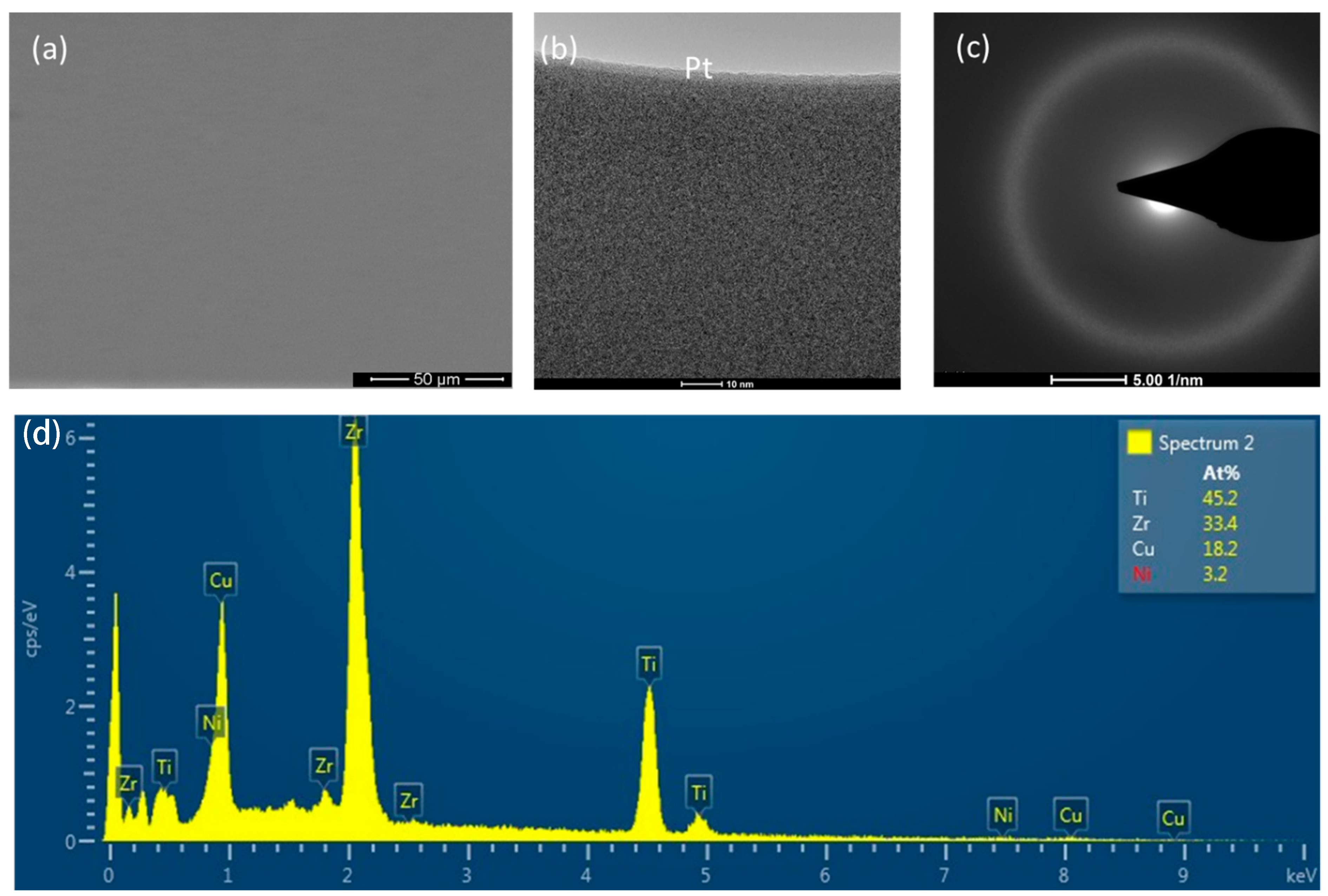
3.1. Scanning Electron Microscopy (SEM) Investigation

The microstructure of presently investigated Zr-based BMGs together with a corresponding EDX spectrum is revealed in Figure 1. Figure 1a shows the SEM image of a metallographic polished sample, whereas Figure 1b exhibits the TEM micrograph with corresponding diffraction pattern in Figure 1c. As expected, the microstructure (both SEM and TEM) is featureless and amorphous in nature, as confirmed by the hollow ring in the diffraction pattern (Figure 1c). In addition, the BMG is homogeneous in nature and there is no existence of any defects, such as the porosities and the cavities. The EDX spectrum, as shown in Figure 1d, shows the presence of all constituent elements except beryllium (Be). The amount of Be in the material was out of the detection range of the EDX.

3.2. In Situ Compression of Micro-Pillars

Fabricated micro-pillars on the polished BMG samples are shown in Figure 2. Figure 2a shows an array of representative micro-pillars that were fabricated in the middle of a 30 µm crater, together with a high magnification image of different diameter micro-pillars in Figure 2b–d. The average diameter of the micro-pillars is as follows: 3.1 ± 0.05 µm, 4.05 ± 0.06 µm and 4.98 ± 0.05 µm. The micro-pillars in this study are somewhat tapered (<2°) in nature, which was not possible to avoid as a result of material-ion beam interaction [27].
During in situ compression, load-displacement curves were logged in the computer system, which were then converted into stress–strain curves, according to the method explained in Section 2.3. To demonstrate the effect of strain rate and pillar diameter on stress–strain behaviour, the curves were aggregated into two different groups. Figure 3 exhibits the effect of pillar diameter on a given strain rate, whereas Figure 4 exhibits the effect of strain rate on a given pillar diameter.

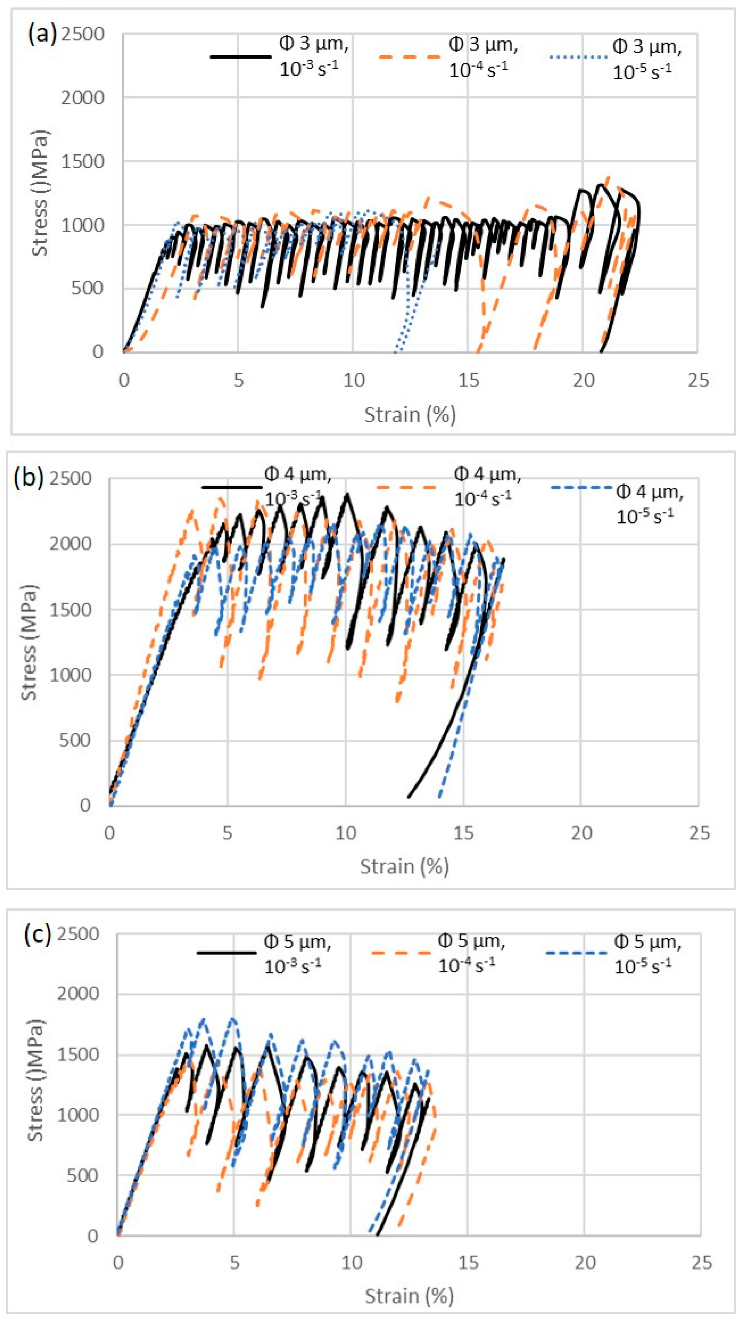
3.2.1. Effect of Micro-Pillar Diameter on Stress–Strain Curves

The effect of micro-pillar diameter on a given strain rate during compression is shown in Figure 3a–c, for strain rate of 10−3, 10−4 and 10−5 s−1, respectively. Irrespective of strain rates, the general trend is that the Ø 3 µm micro-pillar exhibits the lowest strength followed by Ø 5 µm and Ø 4 µm micro-pillars. In addition to that, numerous stress drop-ins were noticed, which was due to the formation and propagation of slip/shear planes.
Such stress–strain behaviour of the BMG can be explained in terms of its structure. The usual flow mechanism of materials, such as dislocation glides, dislocation sliding and rearranging of the crystal structure, is absent in the BMG. As a result, the incremental strength of material in a reduced size that one would expect in (nano-) crystalline materials was absent. In contrast, as reported by Greer et al. [31], the strength of BMGs is due to its interatomic bonding among the atomic arrangement.

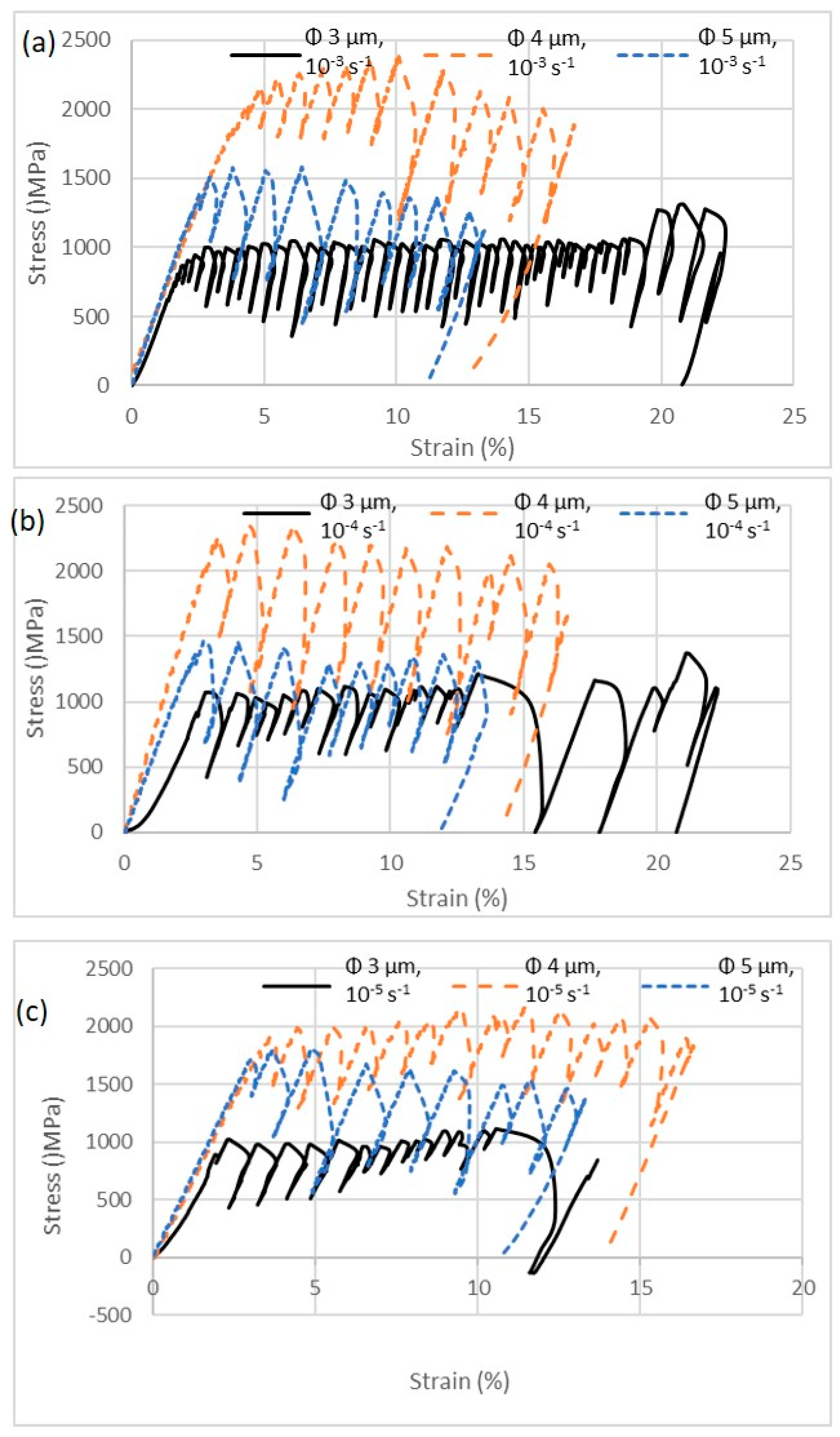
3.2.2. Effect of Strain Rate on Stress–Strain Curves

The effect of strain rate on a given micro-pillar diameter during compression is shown in Figure 4a–c for pillar Ø of 3, 4 and 5 µm, respectively. Irrespective of micro-pillar diameter, strain rate has insignificant effect on the strength of the presently investigated BMG material.
Such negligible effect of strain rate on the strength of the BMG can be described in view of a constitutive model such as the James–Cook equation, as given in Equation (1) [32]:
σ = σ 0 + B ε n 1 + C ln ε ˙ ϵ 0 ˙ 1 T * m
where σ is the yield strength; σ 0 and ε 0 ˙ are reference yield stress and reference strain rate, respectively; ε is the strain; n is the work-hardening coefficient; B, C and m are the material related factors. T* is calculated [32]:
T * = T T r T m T r
where T is the room temperature; Tm is the melting temperature and Tr is the reference temperature, at which σ 0 and ε 0 ˙ are measured. For a given material, such as Zr-based BMGs in the present study, B, C, and m values are constants as well as σ 0 + B ε n , as reported by Meyers et al. [33]. At the given experimental (room) temperatures, the term of [1 − (T*)m] does not change with increasing the strain rate. Thus, Equation (1) can be rewritten as:
σ = K 1 + C ln ε ˙ ϵ 0 ˙
where K is a material-depending constant and C = 0.030 [33] in the present study. Let’s consider the reference strain rate ( ε 0 ) ˙ as 10−3 s−1, which was the highest strain rate investigated in this study. In that case, the change of yield strength of the presently investigated BMG falls within 9–13%, as the strain rate decreases from 10−3 to 10−5 s−1. This range (9–13%) is within the scattering of the yield strength value, as given in Table 1, due to the room temperature brittle behaviour of the BMG.
The features in the stress–strain curves represent the state of physical deformation that took place during compression. The process was recorded via videos, as mentioned above. A representative correlation of such physical deformation states, with that of the corresponding strain interval, is shown in Figure 5, for micro-pillars of Ø 3 µm under 10−3 s−1 strain rate. Figure 5a represents the initiation of slip/shear plane after yielding. Figure 5b exhibits a well-fined slip/shear plane due to further propagation of the slip/shear plane, which continued to take place until the complete fracture took place, as shown in Figure 5c. It is interesting to note that initially the shear/slip plane form near to the top surface of the micro-pillar (Figure 5a) and can be termed as lower order slip planes due to higher stress concentration. As the loading continues, subsequent higher order slip planes start to form, as indicated by arrows in Figure 5c.
Some key mechanical properties of the material, as derived from the stress–strain curves, are summarised in Table 1. Each of the data includes a spread which represents the standard deviation obtained from three individual measurements.
The graphical representation of the mechanical properties of the BMGs investigated in the present research is shown in Figure 6 for ease of comparison. Figure 6a exhibits the effect of micro-pillar diameter and strain rate on yield strength of the BMG, whereas Figure 6b exhibits the effect of the micro-pillar diameter and strain rate on ultimate tensile strength (UTS) of the BMGs. From Figure 6 it is evident that both the yield and ultimate compressive strength of the BMGs increase with the increase of micro-pillar diameters, up to 4 µm. Beyond that, the yield and ultimate compressive strength decrease. The reason behind that is still indistinct and could be related to the critical size of the micro-pillar. However, before making such a claim, further investigation covering wider experimental parameters (such as micro-pillar size and strain rate) is required, which is out of the scope of the present manuscript. As reported by Wang et al. [34], not only the elemental composition of BMG, but also the casting technique may influence its overall strength and plasticity. For example, they investigated Ti41Zr25Be28Fe6 (at. %) BMGs at macro-scale, which exhibited about 1874–1998 MPa of strength. It is interesting to note that presently investigated BMGs fall short of such strength (Table 1) which could be attributed to their elemental composition as well as having scale-dependent (micro- vs. macro-scale) properties.
On the other hand, the effect of strain rate on yield and ultimate compressive strength diminishes with increasing micro-pillar diameter. As the strain rate decreases from 10−3 s−1 to 10−5 s−1, the difference decreases in both yield and ultimate compressive strength for a given micro-pillar diameter. According to Johnson et al. [35], there is a linear relationship with the elastic modulus of BMGs with respect to extrinsic size, which is in contrast to recent reports, where the authors have claimed increasing yield stress of Mg-based [36,37] and Zr-based [38] BMGs as a result of the increase of corresponding micro-pillar diameters. A similar observation was also reported by Lai et al. [39], where the authors reported about a 25–86% increase of yield strength over that of the bulk specimens and correlated it with the Weibull statistics for brittle materials. Such a reported size effect may be due to two possible reasons: (i) artefacts that are unavoidable in such ex situ experiments, as explained by Volkert et al. [40] and Schuster et al. [41], and (ii) the presence of a relatively ductile element, such as aluminium (Al) in the composition of the BMGs. In contrast to that, Kuzmin et al. [42] have reported that the yield stress of BMG is size independent, as with increasing the size of the micro-pillars, the ductile-to-brittle transition took place under compression. This statement was made based on their experiments on micro-pillars in the range of 90–600 nm under in situ TEM experiments. The size range investigated in their study may fall well under the critical transition size range, where such effects were noticed. As reported by Tian et al. [43], such a size dependent deformation mechanism of the BMGs is also affected by the strain rate and the ion beam irradiation, along with the thermal history of the material.

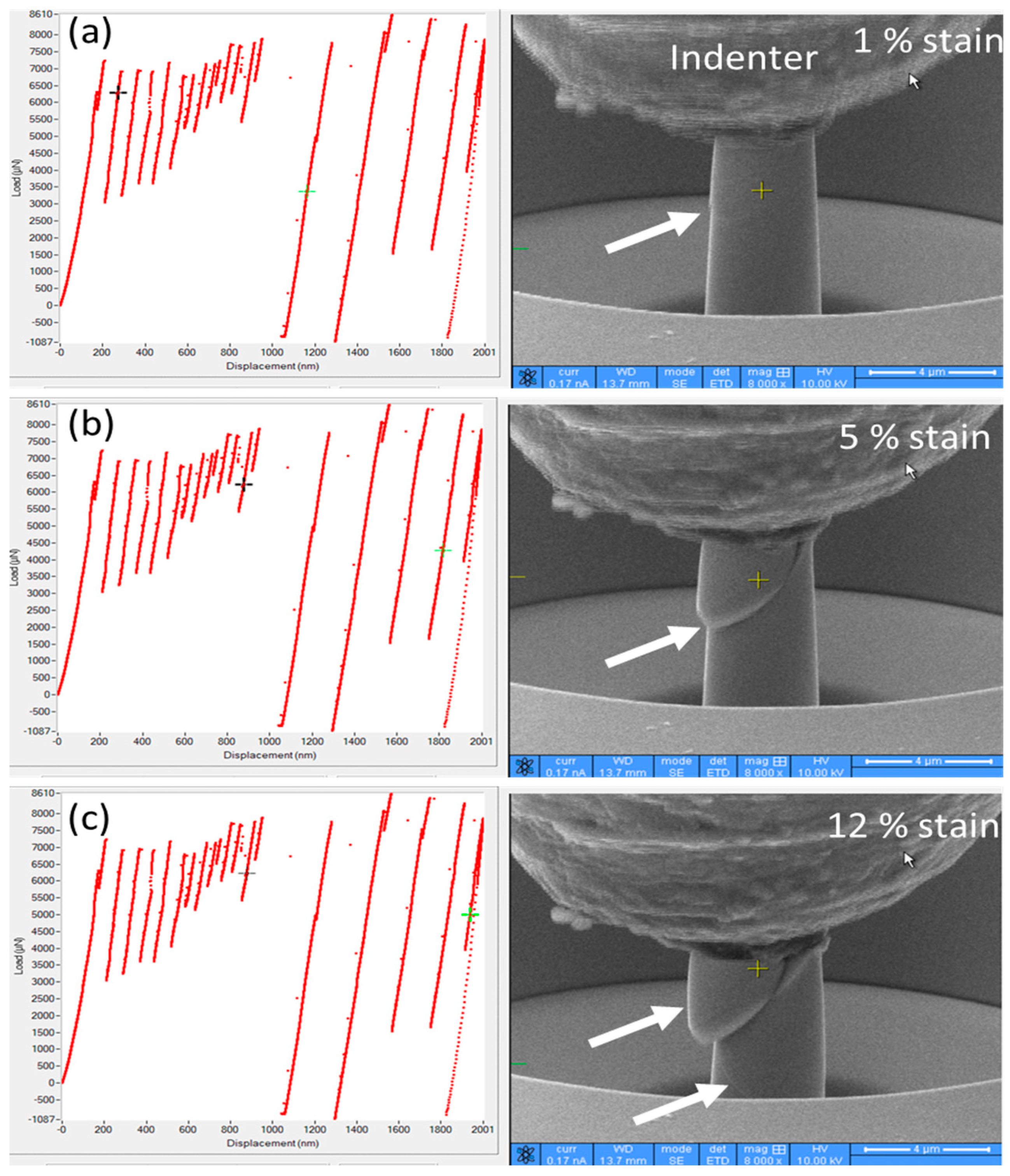
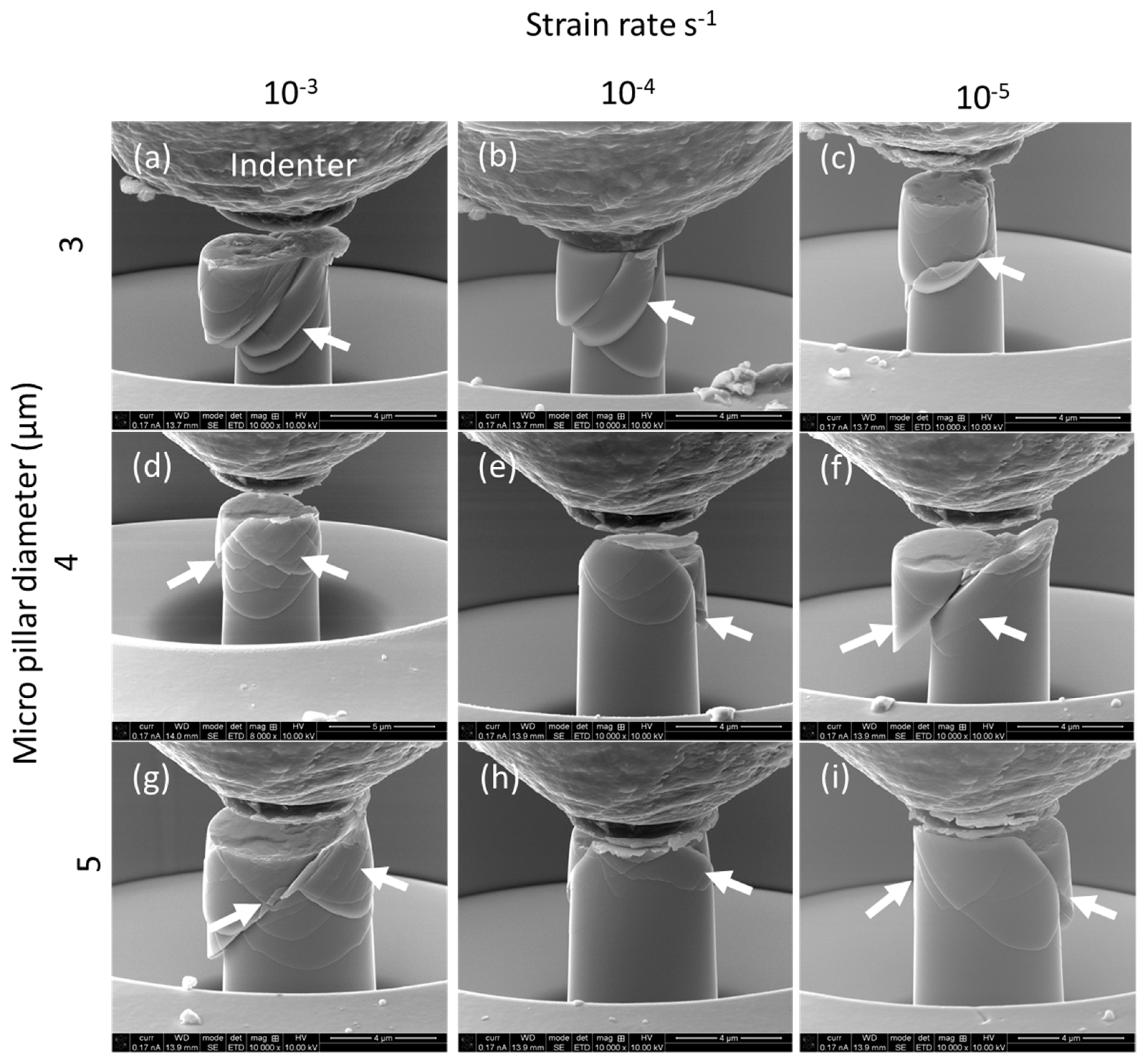
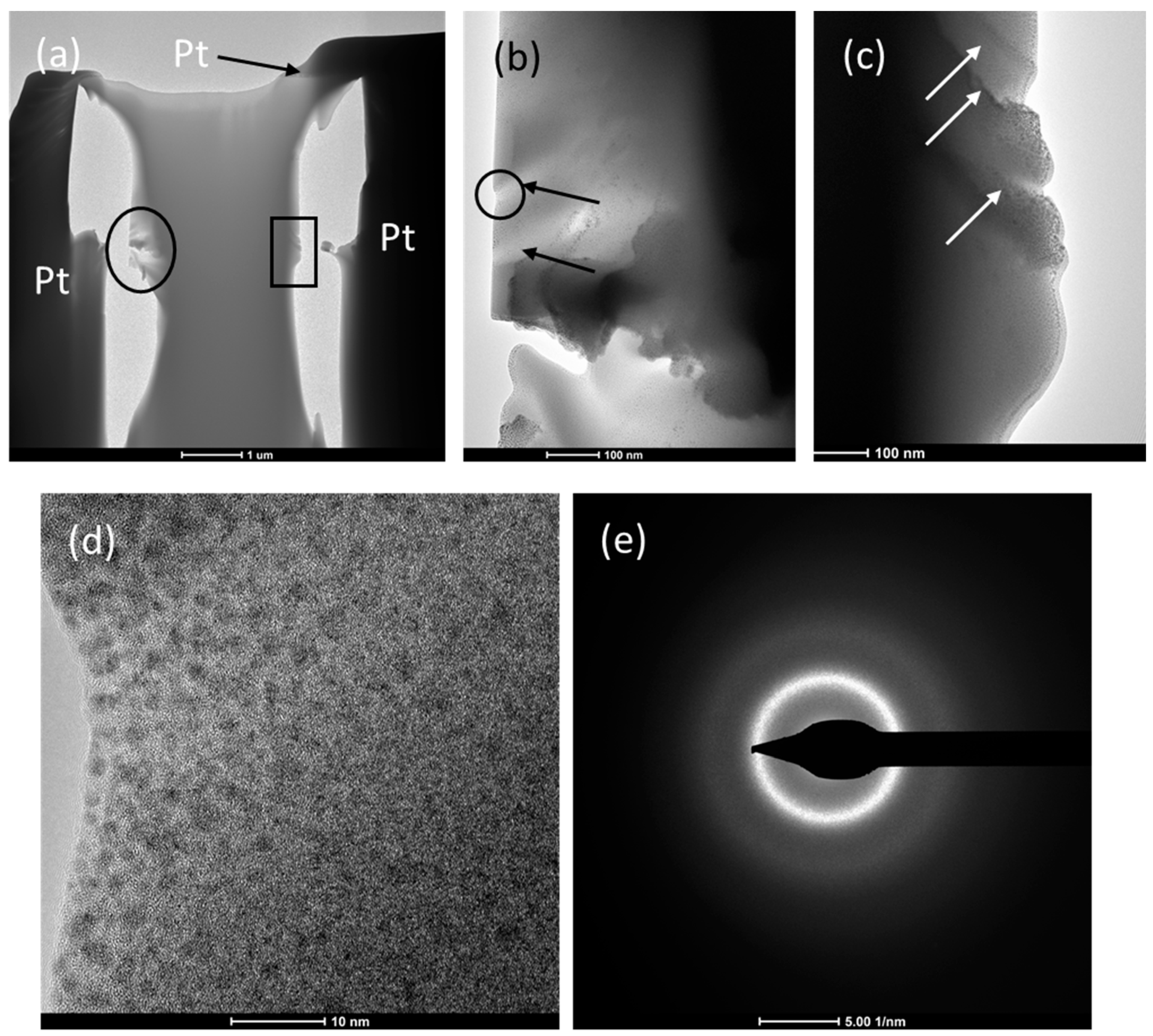
3.3. Deformation of Micro-Pillars during Compression

After the compression tests, deformed pillars were investigated further with SEM. Both the effect of pillar size and the strain rate on the morphology of deformed micro-pillars are shown in Figure 7. Irrespective of micro-pillar size and strain rate, abundant slip and shear bands are visible on the surface of the micro-pillars. It is also interesting to note that the slip/shear bands do not follow any specific direction, rather, they criss-cross each other.
The shear/slip marks on deformed micro-pillar surfaces shows the proof that the local plastic flow of the material took place in the crack tip, as a macroscopic fracture progress in terms of slip/shear planes [44]. This local plastic flow can eventually arrest the crack tip and made it blunt, where progressive local separation still occurs in terms of ductile fracture, which will be evident by the TEM observation of the deformed micro-pillars, as reported in below. As the shear bands are introduced in the materials as load accommodating mechanism, the material in the shear bands became softened as a result of the adiabatic heating and the shear dilatation [45]. As a result, the propagation of the crack can be considered as a viscous flow of fluids in a channel, as proposed by Tao et al. [46]. As the formation and progression of the cracks are subjected to a plastic deformation process, the crack tip becomes separated and leaves a mark resembling the one reported on the fracture surface of the micro-pillar by Wang et al. [47,48]. As can also be seen in Figure 7, lower strain rate seems to introduce lower shear band intensity on the deformed surface of the micro-pillars. This was due to the fact that, at a relatively lower strain rate, there is enough time for the material to respond and accommodate the stress in the form shear/slip bands. However, this is not the case during higher strain rates, where higher order slip/shear planes initiate before the completion of the lower order slip/shear planes. A similar observation was also reported by Tao et al. [46] in the case of the deformation of Ti-based BMGs in a hydrogen- and argon gas-mixed atmosphere.
To achieve further insights on the formation and propagation of such slip planes, TEM samples were prepared on selected deformed micro-pillars, which show the extent of the slip/shear planes. Figure 8 shows the result of TEM examination on a deformed micro-pillar of Ø 3 µm at a 10−3 s−1 strain rate. Figure 8a exhibits the bright field TEM (BF-TEM) image of a whole deformed micro-pillar, whereas Figure 8b,c shows the high-magnification TEM images of the area marked by ovals and rectangles in Figure 8a,b, respectively. Figure 8b clearly shows the individual slip bands, which are approximately 100’s of nm thick. As the BMG is amorphous in nature, no dislocations and stacking faults were observed, which would otherwise be the prominent load accommodation mechanisms, as reported in the case of crystalline materials [49,50]. The existence and extension of shear planes are evident in Figure 8b,c, as marked by the arrows. To investigate the deformation that took place on slip planes, high resolution TEM (HRTEM) images of the marked area (oval) of Figure 8b is shown in Figure 8d. As evident from Figure 8d, separation of the shear band occurs in a ductile mode without the presence of any voids and cavities. This observation contradicts the proposed damage modes of the BMG by Wang et al. [51], where the authors mentioned the presence of cavities in the plastic zone of the crack tip. There was no evidence of the nanocrystal formation in the shear bands, as evidenced by the selected area electron diffraction (SAED) pattern shown in Figure 8e, which was taken from the region of Figure 8d. However, a certain segregation is evident in Figure 8d, and origin of that is not fully understood.
Yield strength of a material is considered a boundary between the elastic and plastic deformation of a given material. The strength of crystalline materials is mostly due to intrinsic frictional stress, as a result of different dislocation motion mechanisms (i.e., the Peierls force) documented in the literature [52]. As BMG material lacks crystallinity, the yield strength of BMGs is considered to be associated with the cohesive strength among atomic clusters. The movement of such atomic clusters is considered an ‘elementary deformation unit’, as reported by Tao et al. [46]. This ‘elementary deformation unit’ is oblivious to external strain rate. On the other hand, the ultimate compressive strength of the material is related to the propagation of the cracks due to shear process, which is subjected to strain rate. This is the most probable explanation towards the insignificant effects of strain rate on stress–strain behaviour of the presently investigated BMG material.
Based on the above experimental evidence, it can be stated that the deformation of the BMGs took place due to the inhomogeneous flow of materials in a shear band formation. As BMG materials lack crystallinity, such a shear band formation introduces ‘work-softening’ [29] and thus, there is no momentary recovery once the slip process is initiated. In the plastic region of stress–strain curves, serrated flow is observed. This type of flow behaviour is unique to BMG materials and is associated with a sudden load drop with respect to the movement of the shear bands. Different researchers have explained the origin of such serrated flow in BMGs differently. Xie et al. [53] has investigated the origin of serrated flow in BMGs via in situ thermal imaging techniques and linked it with shear band activities. The origin of this serrated flow is due to the released heat content for each individual serration that apparently appears as a slip plane/line on the surface of deformed material. However, Brechtl et al. [54] has compared serrated flow with microscopic structural defects in the BMGs that initial shear bands. On the other hand, Liu et al. [55] blame structural inhomogeneity as the cause of serrated flow. Thus, the origin of serrated flow is a complex phenomenon that is explained by different researchers; because it include local heating effects together with structural inhomogeneity, as well as defects in micro-scales. Upon yielding, the BMG tends to form localized shear bands that travel the width of the micro-pillar. This type of plastic flow of materials through the formation of shear bands was also reported by Cheng et al. [13], in the case of nano-indentation, and Fleury et al. [20] at the sides of wear tracks on amorphous alloy surfaces. As a result of these, BMGs exhibit limited ductility and strain accommodation, as the crack can go through highly localized shear bands easily.

4. Conclusions

The present work investigates the effects of micro-pillar diameter and strain rate on the deformation behaviour of Zr-based BMGs subjected to in situ micro-pillar compression. Furthermore, deformed micro-pillars are examined via scanning and transmission electron microscopy to understand the fundamental deformation behaviour. In view of the findings and discussion, the following conclusive remarks could be made on the current work:
The yield and ultimate compressive strength of the presently investigated Zr-based BMGs increases with the increase of micro-pillar diameter up to 4 µm; it then decreases with a further increase of micro-pillar diameter. This behaviour was noticed irrespective of strain rate.
The effect of strain rate on yield and ultimate compressive strength decreases with the increase of micro-pillar diameter. The stress–strain curves exhibit serrated flow in the plastic region, followed by sudden drop-ins of stress as a result of the ‘work-softening’ of the material, due to the absence of any resistance of the crystalline structure towards plastic flow.
The general deformation behaviour involves the initiation of slip/shear as a response in order to accommodate initial loading, followed by the propagation and formation of higher order slip/shear planes, until the complete fracture of the micro-pillar.

Author Contributions

Conceptualization, T.T. and A.K.; methodology, A.K.B.; validation, T.T., A.K. and A.K.B.; formal analysis, T.T.; investigation, T.T.; resources, T.T.; data curation, A.K.B.; writing—original draft preparation, T.T.; writing—review and editing, A.K.; visualization, A.K.B.; supervision, A.K.; project administration, T.T. All authors have read and agreed to the published version of the manuscript.

Funding

This research received no external funding.

Data Availability Statement

Available on request from the authors.

Conflicts of Interest

The authors declare no conflict of interest.

References

  1. Greer, A.L. Metallic glasses. Science 1995, 267, 1947–1953. [Google Scholar] [CrossRef]
  2. Johnson, W.L. Bulk glass-forming metallic alloys: Science and technology. MRS Bull. 1999, 24, 42–56. [Google Scholar] [CrossRef]
  3. Inoue, A. Stabilization of metallic supercooled liquid and bulk amorphous alloys. Acta Mater. 2000, 48, 279–306. [Google Scholar] [CrossRef]
  4. Wang, W.-H.; Dong, C.; Shek, C. Bulk metallic glasses. Mater. Sci. Eng. R Rep. 2004, 44, 45–89. [Google Scholar] [CrossRef]
  5. Ashby, M.; Greer, A.L. Metallic glasses as structural materials. Scr. Mater. 2006, 54, 321–326. [Google Scholar] [CrossRef]
  6. Ishida, M.; Takeda, H.; Nishiyama, N.; Kita, K.; Shimizu, Y.; Saotome, Y.; Inoue, A. Wear resistivity of super-precision microgear made of Ni-based metallic glass. Mater. Sci. Eng. A 2007, 449, 149–154. [Google Scholar] [CrossRef]
  7. Hiromoto, S.; Tsai, A.P.; Sumita, M.; Hanawa, T. Corrosion behavior of Zr65Al7.5Ni10Cu17.5 amorphous alloy for biomedical use. Mater. Trans. 2001, 42, 656–659. [Google Scholar] [CrossRef] [Green Version]
  8. Loye, A.; Kwon, H.-K.; Dellal, D.; Mota, R.M.O.; Lee, S.; Davis, R.; Nagle, N.; Doukas, P.; Schroers, J.; Lee, F.Y.; et al. Biocompatibility of platinum-based bulk metallic glass in orthopedic applications. Biomed. Mater. 2021, 16, 045018. [Google Scholar] [CrossRef] [PubMed]
  9. Han, K.; Jiang, H.; Wang, Y.; Qiang, J.; Yu, C. Antimicrobial Zr-based bulk metallic glasses for surgical devices applications. J. Non-Cryst. Solids 2021, 564, 120827. [Google Scholar] [CrossRef]
  10. Nagireddi, S.; Majumdar, B.; Bonta, S.; Diraviam, A.B. High-Density Bulk Metallic Glasses and Their Composites for Kinetic Energy Penetrator Applications: Process, Structure and Properties. Trans. Indian Inst. Met. 2021, 74, 2117–2134. [Google Scholar] [CrossRef]
  11. Telford, M. The case for bulk metallic glass. Mater. Today 2004, 7, 36–43. [Google Scholar] [CrossRef]
  12. Burgess, T.; Ferry, M. Nanoindentation of metallic glasses. Mater. Today 2009, 12, 24–32. [Google Scholar] [CrossRef]
  13. Cheng, L.; Jiao, Z.M.; Ma, S.G.; Qiao, J.W.; Wang, Z. Serrated flow behaviors of a Zr-based bulk metallic glass by nanoindentation. J. Appl. Phys. 2014, 115, 084907. [Google Scholar] [CrossRef]
  14. Ketov, S.; Louzguine-Luzgin, D. Localized shear deformation and softening of bulk metallic glass: Stress or temperature driven? Sci. Rep. 2013, 3, 2798. [Google Scholar] [CrossRef]
  15. Linderoth, S.; Pryds, N.; Eldrup, M.; Pedersen, A.; Ohnuma, M.; Zhou, T.-J.; Gerward, L.; Jiang, J.; Lathe, C. Bulk Mg-Cu-Y-Al alloys in the amorphous, supercooled liquid and crystalline states. In MRS Online Proceedings Library; Cambridge University Press: Cambridge, UK, 2000; Volume 644, pp. 411–4112. [Google Scholar]
  16. Inoue, A.; Negishi, T.; Kimura, H.M.; Zhang, T.; Yavari, A.R. High packing density of Zr-and Pd-based bulk amorphous alloys. Mater. Trans. JIM 1998, 39, 318–321. [Google Scholar] [CrossRef] [Green Version]
  17. Gang, C.; Ferry, M. Crystallization of Mg-based bulk metallic glass. Trans. Nonferrous Met. Soc. China 2006, 16, 833–837. [Google Scholar]
  18. Huang, Y.; Shen, J.; Chen, J.J.; Sun, J. Critical cooling rate and thermal stability for a Ti-Zr-Ni-Cu-Be metallic glass. J. Alloys Compd. 2009, 477, 920–924. [Google Scholar] [CrossRef]
  19. Fu, X.-Y.; Rigney, D. Tribological Characteristics of Zr41.2Ti13.8Cu12.5Ni10.0Be22.5 Bulk Metallic Glass. In MRS Online Proceedings Library (OPL); Cambridge University Press: Cambridge, UK, 1998; Volume 554. [Google Scholar]
  20. Fleury, E.; Lee, S.; Ahn, H.-S.; Kim, W.; Kim, D. Tribological properties of bulk metallic glasses. Mater. Sci. Eng. A 2004, 375, 276–279. [Google Scholar] [CrossRef]
  21. Blau, P.J. Friction and wear of a Zr-based amorphous metal alloy under dry and lubricated conditions. Wear 2001, 250, 431–434. [Google Scholar] [CrossRef]
  22. Tao, P.; Yang, Y.; Ru, Q. Effect of rotational sliding velocity on surface friction and wear behavior in Zr-based bulk metallic glass. J. Alloys Compd. 2010, 492, L36–L39. [Google Scholar] [CrossRef]
  23. Kim, J.-J.; Choi, Y.; Suresh, S.; Argon, A.S. Nanocrystallization during nanoindentation of a bulk amorphous metal alloy at room temperature. Science 2002, 295, 654–657. [Google Scholar]
  24. Yavari, A.; Filho, W.B.; Rodrigues, C.; Greer, A.; Uriarte, J.; Huenen, G.; Vaughan, G.; Inoue, A. FeNiB-based metallic glasses with fcc crystallisation products. J. Non-Cryst. Solids 2002, 304, 44–50. [Google Scholar] [CrossRef]
  25. Gloriant, T. Microhardness and abrasive wear resistance of metallic glasses and nanostructured composite materials. J. Non-Cryst. Solids 2003, 316, 96–103. [Google Scholar] [CrossRef]
  26. Maddala, D.R.; Hebert, R.J. Sliding wear behavior of Fe50−xCr15Mo14C15B6Erx (x = 0, 1, 2 at%) bulk metallic glass. Wear 2012, 294, 246–256. [Google Scholar] [CrossRef]
  27. Misra, A.; Hirth, J.; Hoagland, R. Length-scale-dependent deformation mechanisms in incoherent metallic multilayered composites. Acta Mater. 2005, 53, 4817–4824. [Google Scholar] [CrossRef]
  28. Giannuzzi, L.A. Introduction to Focused Ion Beams: Instrumentation, Theory, Techniques and Practice; Springer Science & Business Media: Berlin/Heidelberg, Germany, 2004. [Google Scholar]
  29. Zhang, H.; Schuster, B.; Wei, Q.; Ramesh, K. The design of accurate micro-compression experiments. Scr. Mater. 2006, 54, 181–186. [Google Scholar] [CrossRef]
  30. Uchic, M.D.; Shade, P.A.; Dimiduk, D.M. Micro-compression testing of fcc metals: A selected overview of experiments and simulations. JOM 2009, 61, 36–41. [Google Scholar] [CrossRef]
  31. Greer, J.R.; de Hosson, J.T.M. Plasticity in small-sized metallic systems: Intrinsic versus extrinsic size effect. Prog. Mater. Sci. 2011, 56, 654–724. [Google Scholar] [CrossRef]
  32. Johnson, G.R.; Hoegfeldt, J.M.; Lindholm, U.S.; Nagy, A. Response of various metals to large torsional strains over a large range of strain rates—Part 1: Ductile metals. J. Eng. Mater. Technol. 1983, 105, 42–47. [Google Scholar] [CrossRef]
  33. Meyers, M.A. Dynamic Behavior of Materials; John Wiley & Sons: Hoboken, NJ, USA, 1994. [Google Scholar]
  34. Wang, X.; Gong, P.; Yao, K.-F. Mechanical behavior of bulk metallic glass prepared by copper mold casting with reversed pressure. J. Mater. Process. Technol. 2016, 237, 270–276. [Google Scholar] [CrossRef]
  35. Johnson, W.; Samwer, K. A universal criterion for plastic yielding of metallic glasses with a (T/T g) 2/3 temperature dependence. Phys. Rev. Lett. 2005, 95, 195501. [Google Scholar] [CrossRef] [Green Version]
  36. Lee, C.; Huang, J.; Nieh, T. Sample size effect and microcompression of Mg65Cu25Gd10 metallic glass. Appl. Phys. Lett. 2007, 91, 161913. [Google Scholar] [CrossRef]
  37. Zheng, Q.; Cheng, S.; Strader, J.; Ma, E.; Xu, J. Critical size and strength of the best bulk metallic glass former in the Mg-Cu-Gd ternary system. Scr. Mater. 2007, 56, 161–164. [Google Scholar] [CrossRef]
  38. Cheng, S.; Wang, X.-L.; Choo, H.; Liaw, P.K. Global melting of Zr57Ti5Ni8Cu20Al10 bulk metallic glass under microcompression. Appl. Phys. Lett. 2007, 91, 201917. [Google Scholar] [CrossRef]
  39. Lai, Y.; Lee, C.; Cheng, Y.; Chou, H.; Chen, H.; Du, X.; Chang, C.; Huang, J.; Jian, S.; Jang, J.; et al. Bulk and microscale compressive behavior of a Zr-based metallic glass. Scr. Mater. 2008, 58, 890–893. [Google Scholar] [CrossRef]
  40. Volkert, C.; Donohue, A.; Spaepen, F. Effect of sample size on deformation in amorphous metals. J. Appl. Phys. 2008, 103, 083539. [Google Scholar] [CrossRef]
  41. Schuster, B.; Wei, Q.; Hufnagel, T.; Ramesh, K. Size-independent strength and deformation mode in compression of a Pd-based metallic glass. Acta Mater. 2008, 56, 5091–5100. [Google Scholar] [CrossRef]
  42. Kuzmin, O.; Pei, Y.; Chen, C.; De Hosson, J. Intrinsic and extrinsic size effects in the deformation of metallic glass nanopillars. Acta Mater. 2012, 60, 889–898. [Google Scholar] [CrossRef]
  43. Tian, L.; Wang, X.-L.; Shan, Z.-W. Mechanical behavior of micronanoscaled metallic glasses. Mater. Res. Lett. 2016, 4, 63–74. [Google Scholar] [CrossRef] [Green Version]
  44. Zhang, Z.; Eckert, J.; Schultz, L. Difference in compressive and tensile fracture mechanisms of Zr59Cu20Al10Ni8Ti3 bulk metallic glass. Acta Mater. 2003, 51, 1167–1179. [Google Scholar] [CrossRef]
  45. Spaepen, F. A microscopic mechanism for steady state inhomogeneous flow in metallic glasses. Acta Metall. 1977, 25, 407–415. [Google Scholar] [CrossRef]
  46. Tao, P.; Zhang, W.; Tu, Q.; Yang, Y. Response of large-deformation behavior to strain rates in a bulk-metallic glass by hydrogen. Int. J. Hydrogen Energy 2016, 41, 9690–9695. [Google Scholar] [CrossRef]
  47. Wang, G.; Zhao, D.Q.; Bai, H.Y.; Pan, M.X.; Xia, A.L.; Han, B.S.; Xi, X.K.; Wu, Y.; Wang, W.H. Nanoscale periodic morphologies on the fracture surface of brittle metallic glasses. Phys. Rev. Lett. 2007, 98, 235501. [Google Scholar] [CrossRef] [Green Version]
  48. Wang, G.; Chan, K.; Xu, X.; Wang, W. Instability of crack propagation in brittle bulk metallic glass. Acta Mater. 2008, 56, 5845–5860. [Google Scholar] [CrossRef] [Green Version]
  49. Basak, A.; Pramanik, A.; Prakash, C. Deformation and strengthening of SiC reinforced Al-MMCs during in-situ micro-pillar compression. Mater. Sci. Eng. A 2019, 763, 138141. [Google Scholar] [CrossRef]
  50. Kurdi, A.; Basak, A. Deformation of electrodeposited gradient Co/Sn multilayered coatings under micro-pillar compression. Eng. Fract. Mech. 2018, 204, 138–146. [Google Scholar] [CrossRef]
  51. Wang, Y.W.; Bian, X.L.; Wu, S.W.; Hussain, I.; Jia, Y.D.; Yi, J.; Wang, G. Rate dependent of strength in metallic glasses at different temperatures. Sci. Rep. 2016, 6, 27747. [Google Scholar] [CrossRef] [Green Version]
  52. Hirth, J.P.; Kubin, L. Dislocations in Solids; Elsevier: Amsterdam, The Netherlands, 2009. [Google Scholar]
  53. Xie, X.; Lo, Y.-C.; Tong, Y.; Qiao, J.; Wang, G.; Ogata, S.; Qi, H.; Dahmen, K.A.; Gao, Y.; Liaw, P.K. Origin of serrated flow in bulk metallic glasses. J. Mech. Phys. Solids 2019, 124, 634–642. [Google Scholar] [CrossRef]
  54. Brechtl, J. Complexity analysis of serrated flows in a bulk metallic glass under constrained and unconstrained conditions. Mater. Sci. Eng. A 2020, 771, 138585. [Google Scholar] [CrossRef]
  55. Liu, L.H. Effect of structural heterogeneity on serrated flow behavior of Zr-based metallic glass. J. Alloys Compd. 2018, 766, 908–917. [Google Scholar] [CrossRef] [Green Version]
Figure 1. Microstructure of presently investigated Zr-based BMG: (a) SEM micrograph, (b) TEM micrograph, (c) diffraction pattern and (d) corresponding EDX spectra. Pt denotes platinum that was deposited to protect the material surface in the course of TEM sample preparation in FIB-SEM.
Metals 11 01611 g001
Figure 2. A 52° view of (a) an array of micro-pillars and detailed morphology of each type of micro-pillars: (b) Ø 3 µm, (c) Ø 4 µm and (d) Ø 5 µm.
Metals 11 01611 g002
Figure 3. Effect of micro-pillar diameter on stress–strain curves for a given strain rate: (a) 10−3, (b) 10−4 and (c) 10−5 s−1.
Metals 11 01611 g003
Figure 4. Effect of strain rate on stress–strain curves for a given micropillar diameter: (a) 3, (b) 4 and (c) 5 µm.
Metals 11 01611 g004
Figure 5. Representation of the physical appearance of a micro-pillar at different strain intervals (as marked with arrows) during compression: (a) at 1% strain, (b) at 5% strain, and (c) at 12% strain. The white arrows indicate the location of slip/shear band formation.
Metals 11 01611 g005
Figure 6. Compression of (a) the yield strength and (b) the ultimate tensile strength, in terms of micro-pillar diameter and strain rate.
Metals 11 01611 g006
Figure 7. A 45° SEM view of deformed micro-pillars of different size after compression at different strain rate.
Metals 11 01611 g007
Figure 8. Typical TEM micrographs of a deformed micropillar of Ø 3 µm under 10−3 s−1 strain rate: (a) BF-TEM image, (b,c) high magnification TEM of the area are indicated in (a,d) HRTEM image on region indicated in (b,e) corresponding SAED pattern. Pt denotes platinum that was deposited to protect the material surface in the course of TEM sample preparation in FIB-SEM.
Metals 11 01611 g008
Table 1. Key mechanical properties of the presently investigated Zr-based BMGs, determined from stress–strain curves (Figure 3 and Figure 4).
Pillar Diameter (µm)Strain Rate
(s−1)
Yield Strength (σy),
MPa
Strain at
Yield (%)
Ultimate Compressive Strength (σUTS), MPa
310−3868 ± 262.02 ± 0.26996 ± 43
10−4953 ± 522.92 ± 0.121128 ± 39
10−5 1072 ± 464.86 ± 0.421673 ± 55
410−31967 ± 613.90 ± 0.422265 ± 88
10−41682 ± 643.35 ± 0.221805 ± 129
10−51729 ± 603.81 ± 0.322160 ± 78
510−31493 ± 312.67 ± 0.221720 ± 157
10−41694 ± 613.68 ± 0.591817 ± 92
10−51697 ± 233.06 ± 0.231671 ± 118
Publisher’s Note: MDPI stays neutral with regard to jurisdictional claims in published maps and institutional affiliations.

